EP1954397B1 - Diskontinuierliche zentrifuge, insbesondere zur trennung von melassen von zuckerkristallen in einer kochmasse - Google Patents
Diskontinuierliche zentrifuge, insbesondere zur trennung von melassen von zuckerkristallen in einer kochmasse Download PDFInfo
- Publication number
- EP1954397B1 EP1954397B1 EP06794346A EP06794346A EP1954397B1 EP 1954397 B1 EP1954397 B1 EP 1954397B1 EP 06794346 A EP06794346 A EP 06794346A EP 06794346 A EP06794346 A EP 06794346A EP 1954397 B1 EP1954397 B1 EP 1954397B1
- Authority
- EP
- European Patent Office
- Prior art keywords
- drum
- spade
- spades
- spinner
- scraping
- Prior art date
- Legal status (The legal status is an assumption and is not a legal conclusion. Google has not performed a legal analysis and makes no representation as to the accuracy of the status listed.)
- Active
Links
Images
Classifications
-
- B—PERFORMING OPERATIONS; TRANSPORTING
- B04—CENTRIFUGAL APPARATUS OR MACHINES FOR CARRYING-OUT PHYSICAL OR CHEMICAL PROCESSES
- B04B—CENTRIFUGES
- B04B11/00—Feeding, charging, or discharging bowls
- B04B11/08—Skimmers or scrapers for discharging ; Regulating thereof
-
- C—CHEMISTRY; METALLURGY
- C13—SUGAR INDUSTRY
- C13B—PRODUCTION OF SUCROSE; APPARATUS SPECIALLY ADAPTED THEREFOR
- C13B30/00—Crystallisation; Crystallising apparatus; Separating crystals from mother liquors ; Evaporating or boiling sugar juice
- C13B30/04—Separating crystals from mother liquor
- C13B30/08—Washing residual mother liquor from crystals
- C13B30/10—Washing residual mother liquor from crystals in centrifuges
Definitions
- the invention relates to a discontinuous wringer, especially designed to separate the molasses sugar crystals of a mass cooked.
- discontinuous wringers In the field of industrial processing for the manufacture of sugar, discontinuous wringers are known. These devices comprise a perforated rotary basket, also called centrifugation drum, capable of being loaded with a product cooked mass.
- the basket is rotated by motor means to separate the molasses sugar crystals through a perforated surface, including sieve, helped in particular by a device for clearing.
- the clearing device consisting of one or more nozzles arranged in the drum, allows washing the crystals in the basket with a syrup, water or steam.
- the bottom surface of the basket is opened, and the rotating basket is emptied of the products by means of an unloader device.
- the discharging devices of the prior art have a scraper element, also called spade, unique and able to scrape the perforated wall of the basket, to allow the emptying of products.
- the spade is of small dimension relative to the height of the basket and can be driven in a translation movement, when the drum is rotating, over the entire height of the drum.
- the feeder device has a single spade slightly smaller than the height of the basket to scrape over the entire height of the latter, with a slight vertical movement towards the lower part.
- the structure of the basket of the devices of the prior art is subject, during scraping operations, to poorly constrained distributed and which cause, over time, premature wear of the device, and more particularly the rotating members, namely motor, rotation shaft, bearing ....
- Document is known DE 346233 a discontinuous wringer comprising a centrifuge drum and motor means for rotating the drum in a vertical axis of rotation.
- This wringer has two articulated spades distributed inside the drum. The spades are respectively positioned on the lower and upper parts of the drum.
- Document is known FR 1,394,980 an unloading device for a centrifugal centrifugal centrifuge.
- the wringer has a centrifuge drum whose side portion is perforated and the bottom is pierced with a central opening for unloading the basket.
- This wringer has a single spade that can be driven downhill when unloading products.
- JP 01 015164 a discontinuous wringer having a centrifuge drum and motor means for rotating the drum in a vertical axis of rotation.
- This wringer has two spades in rigid connection, free of rotation relative to the rotation shaft of the drum. These spades revolve around the tree during the spin phase under the action of the products.
- the drum continues to be rotated by the motor, a brake disc blocking the rotation of the spades.
- JP 01 315360 a centrifuge comprising a centrifuge drum.
- Two spades positioned diametrically opposite to the axis of rotation of the drum can scrape the accumulated products on the permeable wall of the drum. These spades are positioned at the same level in the drum and can be driven simultaneously to the descent by means of a jack.
- the document GB 738.825 concerns a discontinuous wringer having a centrifuge drum whose side wall is perforated. This wringer has two spades for scraping the inner perforated wall of the drum.
- the object of the present invention is to provide a discontinuous wringer which overcomes the aforementioned drawbacks and allows a better distribution of forces during scraping operations.
- Another object of the invention is to provide a discontinuous wringer for increasing production rates, in particular by reducing the time required for unloading the wrung product.
- the first spade and the second spade are offset over the height of the drum to scrape the part respectively.
- the wringer having means for moving the second spade in translation of a limited vertical stroke, and means for moving the first spade in translation of a limited vertical stroke, the wringer having in addition, means for controlling each of the two spades independently.
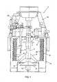
- the invention relates first of all to a discontinuous wringer 1, in particular for separating the molasses from the sugar crystals of a cooked mass.
- said means for scraping the wall 40 are constituted by a set of at least two spades 5, 6 distributed inside the drum and articulated at least in rotation along a vertical axis.
- the drum 2 is housed in a tank 15, arranged vertically, in particular carried by a coaxial rotation shaft 7.
- the motor means 3, in particular electric are secured above and in line with the tank through a carrier structure 16.
- the drum 2 is perforated laterally, in whole or in part, by its permeable wall 40, and open on its upper part, according to known techniques.
- the fluids extracted by centrifugation are discharged from the tank 15 through a discharge outlet 14, in particular lateral.
- the drum of the wringer is furthermore equipped with an opening / closing device 9, located on the lower lower part of the drum, and allowing the unloading of the treated products in a hopper 13, in particular located vertically and vertically. below the tank 15.
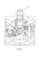
- Each of the spades 5, 6 is vertically attached to the distal end of a rod 21, 22.
- each rod 21, 22 is articulated at its proximal end by means of a pivot connection. Cylinders advantageously make it possible to control the angular orientation of each of the spades 5, 6 in the drum 2.
- the spades 5, 6 are oriented in a release position so as to oppose less resistance to the rotation of the drum 2.
- each of the spades 5, 6 is oriented angularly in the direction of the permeable wall 40 of the drum 2.
- the first spade 5 and the second spade 6 are offset over the height of the drum to scrape respectively the upper part and the lower part of the drum 2.
- the height of the spades 5, 6 corresponds substantially to half the height of the wall 40 of the drum 2, with a slight overlap of the middle portion.
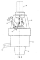
- the first spade 5 is located on an upper portion of the drum 2, the device further having means 23 for moving the second spade 6 in translation of a limited vertical course.
- the rod 21 can then be articulated at its proximal end by means of a sliding pivot connection.
- the drum 2 is secured to the shaft 7 of rotation of the motor means 3 at a hub 8 located on the lower part of the drum.
- the hub 8 may be conical, protruding into the drum.
- the second spade 6 is able to move a limited vertical stroke from an intermediate position of the drum 2 to scrape the lower part of the drum at the hub 8.
- the second spade 6 can then be oriented in said release position without the hub 8 constitutes an obstacle.
- first spade means to move in vertical translation of a limited vertical stroke, like the said second spade.
- the rod 22 can then be articulated at its proximal end by means of a sliding pivot connection
- the wringer can therefore have two spades 5, 6, each articulated in translation and in rotation. During the unloading phase, the two spades can be ordered simultaneously or independently.
- the wringer may have means for controlling each of the two spades independently, in order to obtain a non-simultaneous vertical movement of the spades, allowing better evacuation of the products.
- Said means for controlling the two spades allow, to translate in translation the first spade 5, upper, downwards, then to actuate in translation the second spade 6 below, down, offset.
- the height of the drum may be between 900 mm and 1300 mm.
- the rotation shaft 7 may advantageously be equipped with a deflector 4 making it possible to feed the drum 2 without the products coming to agglutinate at the center of the drum, in particular at the hub 8.
- the fact that the second spade 6 can be raised allows the deflector 4, in a variant, to be lifted without the lower part of the deflector comes into contact with said second spade 6.
- first spade 5 and the second spade 6 are arranged, diametrically opposite, on either side of the axis of rotation of the drum 2. This arrangement advantageously allows to distribute the best efforts induced during scraping, including to preserve the rotating parts of the wringer.
- other provisions may be considered.
- the hub 8 is perforated so as to constitute a discharge outlet of the products contained in the drum 2.
- the wringer then has a shutter 9 adapted to close or open said exhaust outlet.
- the shutter 9 further has translational means 10 for disengaging the shutter 9 from the bottom 41 of the drum 2, thereby opening the discharge outlet.
- the translation means 10 may be constituted by a hydraulic jack device for raising or lowering the shutter 9.
- the wringer 1 may further be equipped with a lighting device 11 fixed or mobile. As illustrated in figure 1 this lighting device may be constituted by at least one tubular conduit 11 disposed vertically in the drum, said tubular pipe being equipped with one or more nozzles for spraying a fluid such as water, syrup, steam, or the like.
- a product treatment method in particular for separating the molasses from the sugar crystals of a cooked mass used in the batch wringer 1 according to the invention, is here also described. This method is not part of the invention as claimed.
Landscapes
- Chemical & Material Sciences (AREA)
- Crystallography & Structural Chemistry (AREA)
- Life Sciences & Earth Sciences (AREA)
- Biochemistry (AREA)
- Organic Chemistry (AREA)
- Centrifugal Separators (AREA)
- Saccharide Compounds (AREA)
- Seasonings (AREA)
Claims (6)
- Diskontinuierliche Zentrifuge (1), nämlich zum Trennen der Melasse von den Zuckerkristallen einer gebackenen Masse, wobei die Zentrifuge wenigstens die folgenden Bestandteile umfasst:- eine Zentrifugiertrommel (2) zur Aufnahme der zu behandelnden Produkte, und umfassend eine durchlässige Wand (40),- Antriebmittel (3) zum Antreiben in Drehung der Trommel (2) gemäß einer vertikalen Drehachse,- eine Entladevorrichtung, die Mittel aufweist, um die durchlässige Innenwand (40) der Trommel abzustreifen,- wobei die besagten Mittel zum Abstreifen der Wand aus einer Einheit von wenigstens zwei Spaten (5,6), die als erster Spaten (5) und zweiter Spaten (6) bezeichnet sind, wobie der erste Spaten (5) und der zweite Spaten (6) innerhalb der Trommel (2) verteilt und jeweils gemäß einer vertikalen Achse drehgelenkig sind, um von einer Freigabeposition, in der der Spaten einen geringeren Widerstand gegen der Drehung der Trommel bietet, in eine Berührungsposition überzugehen, um die besagte durchlässige Wand der Trommel abzustreifen,- wobei die besagten Spaten während der Entladung der Produkte einer vertikalen Translationsbewegung ausgesetzt werden können, dadurch gekennzeichnet, dass der erste Spaten (5) und der zweite Spaten (6) über die Höhe der Trommel zu einander versetzt sind, um jeweils den oberen Teil und den unteren Teil der Trommel abzustreifen, wobei die Zentrifuge Mittel, um den zweiten Spaten um einen beschränkten vertikalen Hub in Translation zu bewegen, sowie Mittel umfasst, um den ersten Spaten (5) um einen beschränkten vertikalen Hub in Translation zu bewegen, wobei die Zentrifuge außerdem Mittel aufweist, um jeden der beiden Spaten unabhängig von einander zu steuern.
- Zentrifuge nach Anspruch 1, bei der die Trommel (2) an der Drehwelle (7) der Antriebmittel (3) im Bereich einer am unteren Teil der Trommel befindlichen Nabe (8) befestigt und der zweiten Spaten (6) geeignet ist, um sich ab einer Zwischenposition der Trommel (2) um einen beschränkten vertikalen Hub zu verschieben, um den unteren Teil der Trommel im Bereich des Mittels (8) abzustreifen.
- Zentrifuge nach einem der Ansprüche 1 bis 2, bei der der erste Spaten (5) und der zweite Spaten (6) diametral gegenüber einander, beiderseits der Drehachse der Trommel angeordnet sind.
- Zentrifuge nach Anspruch 2, bei der die Nabe (8) durchlöchert ist, um einen Abfuhrausgang für die in der Trommel (2) enthaltenen Produkte zu bilden, wobei die Zentrifuge außerdem einen Verschluss (9) umfasst, der geeignet ist, den besagten Abfuhrausgang zu schließen oder zu öffnen.
- Zentrifuge nach Anspruch 4, bei der der Verschluss (9) Translationsmittel (10) umfasst, um diesen von dem Boden (41) der Trommel (2) zu entfernen, wobei der Abfuhrausgang also geöffnet wird.
- Zentrifuge nach einem der Ansprüche 1 bis 5, die außerdem eine Reinigungsvorrichtung (11) umfasst.
Applications Claiming Priority (2)
| Application Number | Priority Date | Filing Date | Title |
|---|---|---|---|
| FR0508919A FR2889974B1 (fr) | 2005-08-31 | 2005-08-31 | Essoreuse discontinue, notamment prevue pour separer la melasse des cristaux de sucre d'une masse cuite |
| PCT/FR2006/001972 WO2007026068A1 (fr) | 2005-08-31 | 2006-08-23 | Essoreuse discontinue, notamment prevue pour separer la melasse des cristaux de sucre d'une masse cuite |
Publications (2)
| Publication Number | Publication Date |
|---|---|
| EP1954397A1 EP1954397A1 (de) | 2008-08-13 |
| EP1954397B1 true EP1954397B1 (de) | 2010-07-21 |
Family
ID=36227009
Family Applications (1)
| Application Number | Title | Priority Date | Filing Date |
|---|---|---|---|
| EP06794346A Active EP1954397B1 (de) | 2005-08-31 | 2006-08-23 | Diskontinuierliche zentrifuge, insbesondere zur trennung von melassen von zuckerkristallen in einer kochmasse |
Country Status (8)
| Country | Link |
|---|---|
| EP (1) | EP1954397B1 (de) |
| CN (1) | CN101277767B (de) |
| AT (1) | ATE474669T1 (de) |
| BR (1) | BRPI0615336A2 (de) |
| DE (1) | DE602006015680D1 (de) |
| FR (1) | FR2889974B1 (de) |
| RU (1) | RU2384371C2 (de) |
| WO (1) | WO2007026068A1 (de) |
Cited By (1)
| Publication number | Priority date | Publication date | Assignee | Title |
|---|---|---|---|---|
| DE102011119265A1 (de) * | 2011-11-24 | 2013-05-29 | Bma Braunschweigische Maschinenbauanstalt Ag | Diskontinuierliche Zentrifuge mit Ausräumer zum Ausräumen eines Produktes |
Families Citing this family (2)
| Publication number | Priority date | Publication date | Assignee | Title |
|---|---|---|---|---|
| DE102012004968A1 (de) * | 2012-03-14 | 2013-09-19 | Bma Braunschweigische Maschinenbauanstalt Ag | Vorrichtung mit einer diskontinuierlich arbeitenden Zentrifuge zum Abtrennen von Sirup aus Zuckerfüllmassen |
| FR3025441B1 (fr) * | 2014-09-10 | 2021-05-07 | Fives Cail Babcock | Tambour de centrifugation et essoreuse equipee d'un tel tambour |
Family Cites Families (7)
| Publication number | Priority date | Publication date | Assignee | Title |
|---|---|---|---|---|
| DE346233C (de) * | 1921-01-04 | 1921-12-28 | Max Stuntz | Ausraeumvorrichtung an Schleudern fuer Zucker u. dgl., insbesondere fuer haengende Schleudern |
| GB738825A (en) * | 1952-09-04 | 1955-10-19 | Shinzo Sumiya | Automatic centrifugal separator |
| FR1394980A (fr) * | 1964-02-27 | 1965-04-09 | Fives Lille Cail | Dispositif de déchargement pour essoreuse centrifuges à marche discontinue |
| SU636034A1 (ru) * | 1977-03-15 | 1978-12-05 | Всесоюзный научно-исследовательский институт сахарной промышленности | Центрифуга дл разделени суспензий |
| JPS6415164A (en) * | 1987-07-08 | 1989-01-19 | Toshimi Kato | Solid/liquid separator |
| JPH01315360A (ja) * | 1988-06-15 | 1989-12-20 | Eiichi Aihara | 遠心分離機 |
| CN2592911Y (zh) * | 2002-11-13 | 2003-12-17 | 刘楚年 | 自密封式调整套衬板沙泵 |
-
2005
- 2005-08-31 FR FR0508919A patent/FR2889974B1/fr not_active Expired - Fee Related
-
2006
- 2006-08-23 RU RU2008112209/12A patent/RU2384371C2/ru not_active IP Right Cessation
- 2006-08-23 EP EP06794346A patent/EP1954397B1/de active Active
- 2006-08-23 CN CN2006800360937A patent/CN101277767B/zh not_active Expired - Fee Related
- 2006-08-23 AT AT06794346T patent/ATE474669T1/de not_active IP Right Cessation
- 2006-08-23 DE DE602006015680T patent/DE602006015680D1/de active Active
- 2006-08-23 WO PCT/FR2006/001972 patent/WO2007026068A1/fr not_active Ceased
- 2006-08-23 BR BRPI0615336-4A patent/BRPI0615336A2/pt active Search and Examination
Cited By (3)
| Publication number | Priority date | Publication date | Assignee | Title |
|---|---|---|---|---|
| DE102011119265A1 (de) * | 2011-11-24 | 2013-05-29 | Bma Braunschweigische Maschinenbauanstalt Ag | Diskontinuierliche Zentrifuge mit Ausräumer zum Ausräumen eines Produktes |
| WO2013076074A1 (de) | 2011-11-24 | 2013-05-30 | Bma Braunschweigische Maschinenbauanstalt Ag | Diskontinuierliche zentrifuge mit ausräumer zum ausräumen eines produktes |
| DE102011119265B4 (de) | 2011-11-24 | 2018-01-04 | Bma Braunschweigische Maschinenbauanstalt Ag | Diskontinuierliche Zentrifuge mit Ausräumer zum Ausräumen eines Produktes |
Also Published As
| Publication number | Publication date |
|---|---|
| WO2007026068A1 (fr) | 2007-03-08 |
| EP1954397A1 (de) | 2008-08-13 |
| CN101277767B (zh) | 2011-09-07 |
| RU2384371C2 (ru) | 2010-03-20 |
| CN101277767A (zh) | 2008-10-01 |
| FR2889974B1 (fr) | 2008-05-09 |
| DE602006015680D1 (de) | 2010-09-02 |
| BRPI0615336A2 (pt) | 2012-12-11 |
| RU2008112209A (ru) | 2009-10-10 |
| FR2889974A1 (fr) | 2007-03-02 |
| ATE474669T1 (de) | 2010-08-15 |
Similar Documents
| Publication | Publication Date | Title |
|---|---|---|
| EP1954397B1 (de) | Diskontinuierliche zentrifuge, insbesondere zur trennung von melassen von zuckerkristallen in einer kochmasse | |
| EP3453772B1 (de) | Zentrifuge zur trennung der zuckerkristalle von der gekochten masse mit flexibler wand | |
| FR2491952A1 (fr) | Perfectionnements aux installations d'alimentation des fours a cuve a gueulard sans cloche | |
| EP0000004B1 (de) | Kontinuierlich arbeitende Filterzentrifuge zum Abscheiden, Waschen oder Entleeren, und Anwendung in einer automatischen Kaffeemaschine | |
| EP0411603B1 (de) | Saftzentrifuge | |
| EP3463006B1 (de) | Mit einer turbine mit gekrümmten klingen ausgestatteter spender von gemahlenem kaffee für eine kaffeemaschine | |
| FR3026025A1 (fr) | Essoreuse centrifuge a marche discontinue | |
| FR3011192A1 (fr) | Essoreuse discontinue | |
| EP0475867B1 (de) | Wäscher-Tür für Massagevorrichtung | |
| FR3042130B1 (fr) | Essoreuse discontinue | |
| FR2594338A1 (fr) | Autoclave de sterilisation avec dispositif de ruissellement | |
| FR2573955A1 (fr) | Dispositif pour le traitement du miel | |
| EP0554347B1 (de) | Schälmaschine für gemüse | |
| EP0211706A2 (de) | Verfahren und Vorrichtung zum Trennen von Feststoff-/Flüssigkeitsanteilen, insbesondere von Fruchtsäften | |
| EP0259200B1 (de) | Gär- oder Mazerationsbehälter mit beweglichem Ausräumer | |
| BE521276A (de) | ||
| EP0212541B1 (de) | Trommelsteinfänger für Rüben und ähnliche Produkte | |
| BE404801A (de) | ||
| FR2479012A1 (fr) | Filtre a plateaux sous pression | |
| BE502268A (de) | ||
| FR3099871A1 (fr) | Dispositif de retournement de pates alimentaires dans une installation de cuisson par friture | |
| FR2517057A1 (fr) | Dispositif d'extraction d'echantillons de jus, notamment dispositif de prise de mout par carottage | |
| BE373636A (de) | ||
| BE338089A (de) | ||
| LU85074A1 (fr) | Procede et dispositif d'extraction d'huile |
Legal Events
| Date | Code | Title | Description |
|---|---|---|---|
| PUAI | Public reference made under article 153(3) epc to a published international application that has entered the european phase |
Free format text: ORIGINAL CODE: 0009012 |
|
| 17P | Request for examination filed |
Effective date: 20080311 |
|
| AK | Designated contracting states |
Kind code of ref document: A1 Designated state(s): AT BE BG CH CY CZ DE DK EE ES FI FR GB GR HU IE IS IT LI LT LU LV MC NL PL PT RO SE SI SK TR |
|
| GRAP | Despatch of communication of intention to grant a patent |
Free format text: ORIGINAL CODE: EPIDOSNIGR1 |
|
| GRAS | Grant fee paid |
Free format text: ORIGINAL CODE: EPIDOSNIGR3 |
|
| GRAA | (expected) grant |
Free format text: ORIGINAL CODE: 0009210 |
|
| AK | Designated contracting states |
Kind code of ref document: B1 Designated state(s): AT BE BG CH CY CZ DE DK EE ES FI FR GB GR HU IE IS IT LI LT LU LV MC NL PL PT RO SE SI SK TR |
|
| REG | Reference to a national code |
Ref country code: GB Ref legal event code: FG4D Free format text: NOT ENGLISH |
|
| REG | Reference to a national code |
Ref country code: CH Ref legal event code: EP |
|
| REG | Reference to a national code |
Ref country code: IE Ref legal event code: FG4D |
|
| REF | Corresponds to: |
Ref document number: 602006015680 Country of ref document: DE Date of ref document: 20100902 Kind code of ref document: P |
|
| REG | Reference to a national code |
Ref country code: SE Ref legal event code: TRGR |
|
| REG | Reference to a national code |
Ref country code: NL Ref legal event code: VDEP Effective date: 20100721 |
|
| LTIE | Lt: invalidation of european patent or patent extension |
Effective date: 20100721 |
|
| PG25 | Lapsed in a contracting state [announced via postgrant information from national office to epo] |
Ref country code: NL Free format text: LAPSE BECAUSE OF FAILURE TO SUBMIT A TRANSLATION OF THE DESCRIPTION OR TO PAY THE FEE WITHIN THE PRESCRIBED TIME-LIMIT Effective date: 20100721 Ref country code: LT Free format text: LAPSE BECAUSE OF FAILURE TO SUBMIT A TRANSLATION OF THE DESCRIPTION OR TO PAY THE FEE WITHIN THE PRESCRIBED TIME-LIMIT Effective date: 20100721 Ref country code: AT Free format text: LAPSE BECAUSE OF FAILURE TO SUBMIT A TRANSLATION OF THE DESCRIPTION OR TO PAY THE FEE WITHIN THE PRESCRIBED TIME-LIMIT Effective date: 20100721 Ref country code: FI Free format text: LAPSE BECAUSE OF FAILURE TO SUBMIT A TRANSLATION OF THE DESCRIPTION OR TO PAY THE FEE WITHIN THE PRESCRIBED TIME-LIMIT Effective date: 20100721 |
|
| REG | Reference to a national code |
Ref country code: IE Ref legal event code: FD4D |
|
| BERE | Be: lapsed |
Owner name: FIVES CAIL Effective date: 20100831 |
|
| PG25 | Lapsed in a contracting state [announced via postgrant information from national office to epo] |
Ref country code: PL Free format text: LAPSE BECAUSE OF FAILURE TO SUBMIT A TRANSLATION OF THE DESCRIPTION OR TO PAY THE FEE WITHIN THE PRESCRIBED TIME-LIMIT Effective date: 20100721 Ref country code: CY Free format text: LAPSE BECAUSE OF FAILURE TO SUBMIT A TRANSLATION OF THE DESCRIPTION OR TO PAY THE FEE WITHIN THE PRESCRIBED TIME-LIMIT Effective date: 20100721 Ref country code: PT Free format text: LAPSE BECAUSE OF FAILURE TO SUBMIT A TRANSLATION OF THE DESCRIPTION OR TO PAY THE FEE WITHIN THE PRESCRIBED TIME-LIMIT Effective date: 20101122 Ref country code: SI Free format text: LAPSE BECAUSE OF FAILURE TO SUBMIT A TRANSLATION OF THE DESCRIPTION OR TO PAY THE FEE WITHIN THE PRESCRIBED TIME-LIMIT Effective date: 20100721 Ref country code: IS Free format text: LAPSE BECAUSE OF FAILURE TO SUBMIT A TRANSLATION OF THE DESCRIPTION OR TO PAY THE FEE WITHIN THE PRESCRIBED TIME-LIMIT Effective date: 20101121 Ref country code: BG Free format text: LAPSE BECAUSE OF FAILURE TO SUBMIT A TRANSLATION OF THE DESCRIPTION OR TO PAY THE FEE WITHIN THE PRESCRIBED TIME-LIMIT Effective date: 20101021 |
|
| PG25 | Lapsed in a contracting state [announced via postgrant information from national office to epo] |
Ref country code: GR Free format text: LAPSE BECAUSE OF FAILURE TO SUBMIT A TRANSLATION OF THE DESCRIPTION OR TO PAY THE FEE WITHIN THE PRESCRIBED TIME-LIMIT Effective date: 20101022 Ref country code: LV Free format text: LAPSE BECAUSE OF FAILURE TO SUBMIT A TRANSLATION OF THE DESCRIPTION OR TO PAY THE FEE WITHIN THE PRESCRIBED TIME-LIMIT Effective date: 20100721 Ref country code: MC Free format text: LAPSE BECAUSE OF NON-PAYMENT OF DUE FEES Effective date: 20100831 |
|
| REG | Reference to a national code |
Ref country code: CH Ref legal event code: PL |
|
| PG25 | Lapsed in a contracting state [announced via postgrant information from national office to epo] |
Ref country code: CH Free format text: LAPSE BECAUSE OF NON-PAYMENT OF DUE FEES Effective date: 20100831 Ref country code: DK Free format text: LAPSE BECAUSE OF FAILURE TO SUBMIT A TRANSLATION OF THE DESCRIPTION OR TO PAY THE FEE WITHIN THE PRESCRIBED TIME-LIMIT Effective date: 20100721 Ref country code: IE Free format text: LAPSE BECAUSE OF FAILURE TO SUBMIT A TRANSLATION OF THE DESCRIPTION OR TO PAY THE FEE WITHIN THE PRESCRIBED TIME-LIMIT Effective date: 20100721 Ref country code: LI Free format text: LAPSE BECAUSE OF NON-PAYMENT OF DUE FEES Effective date: 20100831 |
|
| PLBE | No opposition filed within time limit |
Free format text: ORIGINAL CODE: 0009261 |
|
| STAA | Information on the status of an ep patent application or granted ep patent |
Free format text: STATUS: NO OPPOSITION FILED WITHIN TIME LIMIT |
|
| PG25 | Lapsed in a contracting state [announced via postgrant information from national office to epo] |
Ref country code: CZ Free format text: LAPSE BECAUSE OF FAILURE TO SUBMIT A TRANSLATION OF THE DESCRIPTION OR TO PAY THE FEE WITHIN THE PRESCRIBED TIME-LIMIT Effective date: 20100721 Ref country code: RO Free format text: LAPSE BECAUSE OF FAILURE TO SUBMIT A TRANSLATION OF THE DESCRIPTION OR TO PAY THE FEE WITHIN THE PRESCRIBED TIME-LIMIT Effective date: 20100721 Ref country code: SK Free format text: LAPSE BECAUSE OF FAILURE TO SUBMIT A TRANSLATION OF THE DESCRIPTION OR TO PAY THE FEE WITHIN THE PRESCRIBED TIME-LIMIT Effective date: 20100721 Ref country code: IT Free format text: LAPSE BECAUSE OF FAILURE TO SUBMIT A TRANSLATION OF THE DESCRIPTION OR TO PAY THE FEE WITHIN THE PRESCRIBED TIME-LIMIT Effective date: 20100721 Ref country code: EE Free format text: LAPSE BECAUSE OF FAILURE TO SUBMIT A TRANSLATION OF THE DESCRIPTION OR TO PAY THE FEE WITHIN THE PRESCRIBED TIME-LIMIT Effective date: 20100721 |
|
| 26N | No opposition filed |
Effective date: 20110426 |
|
| PG25 | Lapsed in a contracting state [announced via postgrant information from national office to epo] |
Ref country code: ES Free format text: LAPSE BECAUSE OF FAILURE TO SUBMIT A TRANSLATION OF THE DESCRIPTION OR TO PAY THE FEE WITHIN THE PRESCRIBED TIME-LIMIT Effective date: 20101101 |
|
| PG25 | Lapsed in a contracting state [announced via postgrant information from national office to epo] |
Ref country code: BE Free format text: LAPSE BECAUSE OF NON-PAYMENT OF DUE FEES Effective date: 20100831 |
|
| REG | Reference to a national code |
Ref country code: DE Ref legal event code: R097 Ref document number: 602006015680 Country of ref document: DE Effective date: 20110426 |
|
| PG25 | Lapsed in a contracting state [announced via postgrant information from national office to epo] |
Ref country code: LU Free format text: LAPSE BECAUSE OF NON-PAYMENT OF DUE FEES Effective date: 20100823 Ref country code: HU Free format text: LAPSE BECAUSE OF FAILURE TO SUBMIT A TRANSLATION OF THE DESCRIPTION OR TO PAY THE FEE WITHIN THE PRESCRIBED TIME-LIMIT Effective date: 20110122 |
|
| PG25 | Lapsed in a contracting state [announced via postgrant information from national office to epo] |
Ref country code: TR Free format text: LAPSE BECAUSE OF FAILURE TO SUBMIT A TRANSLATION OF THE DESCRIPTION OR TO PAY THE FEE WITHIN THE PRESCRIBED TIME-LIMIT Effective date: 20100721 |
|
| REG | Reference to a national code |
Ref country code: FR Ref legal event code: PLFP Year of fee payment: 11 |
|
| REG | Reference to a national code |
Ref country code: FR Ref legal event code: PLFP Year of fee payment: 12 |
|
| REG | Reference to a national code |
Ref country code: FR Ref legal event code: PLFP Year of fee payment: 13 |
|
| PGFP | Annual fee paid to national office [announced via postgrant information from national office to epo] |
Ref country code: SE Payment date: 20180725 Year of fee payment: 13 Ref country code: GB Payment date: 20180720 Year of fee payment: 13 |
|
| REG | Reference to a national code |
Ref country code: SE Ref legal event code: EUG |
|
| GBPC | Gb: european patent ceased through non-payment of renewal fee |
Effective date: 20190823 |
|
| PG25 | Lapsed in a contracting state [announced via postgrant information from national office to epo] |
Ref country code: SE Free format text: LAPSE BECAUSE OF NON-PAYMENT OF DUE FEES Effective date: 20190824 |
|
| PG25 | Lapsed in a contracting state [announced via postgrant information from national office to epo] |
Ref country code: GB Free format text: LAPSE BECAUSE OF NON-PAYMENT OF DUE FEES Effective date: 20190823 |
|
| PGFP | Annual fee paid to national office [announced via postgrant information from national office to epo] |
Ref country code: DE Payment date: 20250724 Year of fee payment: 20 |
|
| PGFP | Annual fee paid to national office [announced via postgrant information from national office to epo] |
Ref country code: FR Payment date: 20250723 Year of fee payment: 20 |