EP1953746A2 - Actionneur optique, dispositif de capture optique et enregistrement optique et appareil de reproduction - Google Patents
Actionneur optique, dispositif de capture optique et enregistrement optique et appareil de reproduction Download PDFInfo
- Publication number
- EP1953746A2 EP1953746A2 EP08250205A EP08250205A EP1953746A2 EP 1953746 A2 EP1953746 A2 EP 1953746A2 EP 08250205 A EP08250205 A EP 08250205A EP 08250205 A EP08250205 A EP 08250205A EP 1953746 A2 EP1953746 A2 EP 1953746A2
- Authority
- EP
- European Patent Office
- Prior art keywords
- objective lens
- diffractive element
- lens
- optical axis
- optical
- Prior art date
- Legal status (The legal status is an assumption and is not a legal conclusion. Google has not performed a legal analysis and makes no representation as to the accuracy of the status listed.)
- Withdrawn
Links
Images


Classifications
-
- G—PHYSICS
- G11—INFORMATION STORAGE
- G11B—INFORMATION STORAGE BASED ON RELATIVE MOVEMENT BETWEEN RECORD CARRIER AND TRANSDUCER
- G11B7/00—Recording or reproducing by optical means, e.g. recording using a thermal beam of optical radiation by modifying optical properties or the physical structure, reproducing using an optical beam at lower power by sensing optical properties; Record carriers therefor
- G11B7/08—Disposition or mounting of heads or light sources relatively to record carriers
- G11B7/09—Disposition or mounting of heads or light sources relatively to record carriers with provision for moving the light beam or focus plane for the purpose of maintaining alignment of the light beam relative to the record carrier during transducing operation, e.g. to compensate for surface irregularities of the latter or for track following
- G11B7/0925—Electromechanical actuators for lens positioning
- G11B7/0935—Details of the moving parts
-
- G—PHYSICS
- G11—INFORMATION STORAGE
- G11B—INFORMATION STORAGE BASED ON RELATIVE MOVEMENT BETWEEN RECORD CARRIER AND TRANSDUCER
- G11B7/00—Recording or reproducing by optical means, e.g. recording using a thermal beam of optical radiation by modifying optical properties or the physical structure, reproducing using an optical beam at lower power by sensing optical properties; Record carriers therefor
- G11B7/12—Heads, e.g. forming of the optical beam spot or modulation of the optical beam
- G11B7/125—Optical beam sources therefor, e.g. laser control circuitry specially adapted for optical storage devices; Modulators, e.g. means for controlling the size or intensity of optical spots or optical traces
- G11B7/127—Lasers; Multiple laser arrays
- G11B7/1275—Two or more lasers having different wavelengths
-
- G—PHYSICS
- G11—INFORMATION STORAGE
- G11B—INFORMATION STORAGE BASED ON RELATIVE MOVEMENT BETWEEN RECORD CARRIER AND TRANSDUCER
- G11B7/00—Recording or reproducing by optical means, e.g. recording using a thermal beam of optical radiation by modifying optical properties or the physical structure, reproducing using an optical beam at lower power by sensing optical properties; Record carriers therefor
- G11B7/12—Heads, e.g. forming of the optical beam spot or modulation of the optical beam
- G11B7/135—Means for guiding the beam from the source to the record carrier or from the record carrier to the detector
- G11B7/1353—Diffractive elements, e.g. holograms or gratings
-
- G—PHYSICS
- G11—INFORMATION STORAGE
- G11B—INFORMATION STORAGE BASED ON RELATIVE MOVEMENT BETWEEN RECORD CARRIER AND TRANSDUCER
- G11B7/00—Recording or reproducing by optical means, e.g. recording using a thermal beam of optical radiation by modifying optical properties or the physical structure, reproducing using an optical beam at lower power by sensing optical properties; Record carriers therefor
- G11B7/12—Heads, e.g. forming of the optical beam spot or modulation of the optical beam
- G11B7/135—Means for guiding the beam from the source to the record carrier or from the record carrier to the detector
- G11B7/1392—Means for controlling the beam wavefront, e.g. for correction of aberration
- G11B7/13925—Means for controlling the beam wavefront, e.g. for correction of aberration active, e.g. controlled by electrical or mechanical means
-
- G—PHYSICS
- G11—INFORMATION STORAGE
- G11B—INFORMATION STORAGE BASED ON RELATIVE MOVEMENT BETWEEN RECORD CARRIER AND TRANSDUCER
- G11B7/00—Recording or reproducing by optical means, e.g. recording using a thermal beam of optical radiation by modifying optical properties or the physical structure, reproducing using an optical beam at lower power by sensing optical properties; Record carriers therefor
- G11B2007/0003—Recording, reproducing or erasing systems characterised by the structure or type of the carrier
- G11B2007/0006—Recording, reproducing or erasing systems characterised by the structure or type of the carrier adapted for scanning different types of carrier, e.g. CD & DVD
Definitions
- the present invention relates to a lens actuator including an objective lens for condensing a light beam on an optical storage medium and driving the objective lens in at least a focusing direction and a tracking direction relative to the optical storage medium, an optical pickup devise in which the lens actuator is installed, and an optical recording and reproducing apparatus.
- Some lens actuators of optical pickup devices include a diffractive element for providing compatibility with optical storage media of plural types of standards relative to light sources of plural different wavelengths.
- FIG. 1A is a cross-sectional view showing an example of a conventional lens actuator and FIG. 1B is a perspective view showing the conventional lens actuator in FIG. 1A .
- an objective lens 52 and a diffractive element 53 are directly installed on a lens holder 51.
- a passage hole 54 having an effective diameter of a light beam in an optical system is formed at a center portion of the lens holder 51 used as a box casing on which a coil for generating driving power and an elastic support structure not shown in the drawings are installed.
- the objective lens 52 and the diffractive element 53 are fixed on upper and lower ends of the passage hole 54 so as to have the same optical axis.
- FIG. 2A is a cross-sectional view showing an example of a lens actuator on which the diffractive element is disposed so as to have a tilted optical axis relative to the optical axis of the objective lens.
- FIG. 2B is a perspective view showing the lens actuator in FIG. 2A .
- the diffractive element 53 is disposed on the lens holder 51 in a tilted manner relative to the optical axis of the objective lens 52 so as to prevent generation of flare from the diffractive element 53 (refer to Patent Document 1)
- Patent Document 1 Japanese Laid-Open Patent Application No. 2006-139874
- Patent Document 2 Japanese Laid-Open Patent Application No. 8-315393
- Patent Document 2 is capable of preventing the influx of adhesive.
- a thickness of the holder is increased in an entire circumference of the lens holder as long as a height for fitting into a cylindrical surface of an outside diameter of a lens. Lightning and maintaining when plural optical elements are installed are not considered.
- Patent Document 1 discloses a structure of a lens unit in which the objective lens and the diffractive element are adjusted and fixed on the lens holder (support member) and the diffractive element is fixed in a tilted manner.
- Patent Document 1 does not particularly disclose a method for installing the diffractive element in a tilted manner with high accuracy.
- an outer shape of the optical element used as a rotator rotating on the optical axis is formed into a cylindrical shape or columnar shape so as to facilitate manufacturing and improve installation accuracy. Further, a round hole or a stepped round hole is formed in a member on which the optical element is installed and positioning is performed through fitting between the hole and a shaft.
- a center of gravity must correspond to a driving center or a center of an elastic support member movably supporting the casing so as to have a small and light movable unit and prevent undesired accompanied movement.
- a shape or a structure for positioning and fixing the optical element is minimized.
- a positioning support structure by contact among parts namely, a three-point supporting structure, for example, it is desirable to minimize an amount of contact and have a large relative position and distance among three points taking into consideration unevenness, margin or error, or surface roughness of the parts.
- the optical element per se is configured to be light and small, the optical element is required to be enlarged in accordance with a shape structure necessary for positioning relative to the effective diameter in the optical element.
- the shape structure necessary for positioning is also required in the casing used as the movable unit and is required to have no additional size relative to a driving power generating structure and an elastic support structure disposed on an outer shape portion.
- some optical pickup devices include a diffractive element for providing compatibility with optical storage media of plural types of standards relative to light sources of plural different wavelengths.
- Patent Document 1 discloses a lens unit in which an objective lens and the diffractive element are integrated.
- the diffractive element is disposed on a support member in a tilted manner relative to the optical axis of the objective lens so as to prevent generation of flare from the diffractive element.
- Patent Document 1 Japanese Laid-Open Patent Application No. 2006-139874
- Patent Document 1 discloses a structure of a lens unit in which the objective lens and the diffractive element are adjusted and fixed on the support member and the diffractive element is fixed in a tilted manner. However, Patent Document 1 does not particularly disclose a method for installing the diffractive element in a tilted manner with high accuracy.
- an outer shape of the optical element used as a rotator rotating on the optical axis is formed into a cylindrical shape or columnar shape so as to facilitate manufacturing and improve installation accuracy. Further, a round hole or a stepped round hole is formed in a member on which the optical element is installed and positioning is performed through fitting between the hole and a shaft.
- the diffractive element having a concentric structure is used as en element compatible with plural laser wavelengths, the following conditions (1) and (2) are required so as to sufficiently provide functions thereof:
- a center of the diffractive element to be positioned with high accuracy relative to the optical axis of the objective lens corresponds to a center of one of both surfaces of the diffractive element facing the objective lens.
- Patent Document 1 discloses a structure in which the objective lens and the diffractive element are installed on the support member.
- a size of the lens unit as a movable casing may be enlarged and mass of a balancing weight for the lens unit may be increased.
- sensitivity or a high resonance frequency is likely to be reduced due to the enlarged size and the increased balancing weight.
- a more specific object of the present invention is to provide a lens actuator, optical pickup device, and optical recording and reproducing apparatus that can position and fix an objective lens and a diffractive element on a lens holder with high accuracy using a relatively simple structure.
- a lens actuator comprising: an objective lens condensing a light beam on an optical storage medium; a diffractive element providing compatibility with optical storage media of plural types of standards relative to light sources of plural different wavelengths; and a lens holder including the objective lens and the diffractive element in an opposing manner, the objective lens being driven together with the lens holder in at least a focusing direction and a tracking direction relative to the optical storage medium, characterized in that: at least three protrusions are set on the lens holder in directions orthogonal to an optical axis of the objective lens, the protrusions being in contact with at least one of circumferential surfaces of the objective lens and the diffractive element and positioning the objective lens or the diffractive element; and an end surface of the protrusion in contact with at least one of the circumferential surfaces of the objective lens and the diffractive element has a plane surface.
- the circumferential surfaces of the objective lens and the diffractive element are brought into contact with the plane surfaces of the protrusions formed on at least three positions of the lens holder, so that positioning is performed with high accuracy and is less subject to unevenness of parts accuracy.
- a length of the end surface of the protrusion in contact with the objective lens or the diffractive element in a circumferential direction thereof may be set to be shorter than a length of a portion of the protrusion extending in the direction orthogonal to the optical axis of the objective lens.
- the protrusion may be formed into a columnar shape and may be disposed on four positions such that two protrusions are disposed in a radial direction and the remaining two protrusions are disposed in a tangential direction relative to the optical storage medium while forming an angle of 90 degrees between the protrusions.
- each of the columnar-shaped protrusions has a rib shape radial relative to the optical axis of the objective lens and the protrusions are disposed in the radial direction and the tangential direction with the same angle, so that it is possible to realize a high-performance actuator unit in which size control and characteristic control are readily made.
- a portion positioning the objective lens or the diffractive element in an optical axis direction of the objective lens may be removed from the lens holder, the portion being adjacent to the end surface of the protrusion in the optical axis direction of the objective lens.
- the surface in direct contact with the objective lens or the diffractive element adjacent to the protrusion is not used for positioning the objective lens or the diffractive element in the optical axis direction.
- a protrusion positioning at least one of the objective lens and the diffractive element in an optical axis direction of the objective lens may be disposed on a position of the lens holder where the protrusions are not disposed.
- the diffractive element when the diffractive element is rotated on a radial axis or a tangential axis as a rotation axis in the optical storage medium and installed on the lens holder with a tilt relative to the optical axis of the objective lens, in the four columnar-shaped protrusions in contact with an outer cylindrical surface of the diffractive element, plane surfaces of the two protrusions present in a direction orthogonal to the tilted rotation axis among the four protrusions and in contact with the cylindrical surface of the diffractive element may be shifted from the cylindrical surface of the diffractive element without tilt such that the cylindrical surface of the tilted diffractive element is inscribed and a center of a diffracting plane facing the objective lens corresponds to the optical axis of the objective lens.
- this structure it is possible to perform high-accuracy positioning using a simple structure even when the diffractive element is tilted and flare prevention is performed.
- a portion positioning the diffractive element in a tilted manner relative to a surface perpendicular to the optical axis of the objective lens may be removed from the lens holder, the portion being adjacent to the end surfaces of the four columnar-shaped protrusions in a direction of the optical axis of the objective lens where the cylindrical surface of the tilted diffractive element is inscribed.
- a portion positioning the diffractive element in a tilted manner relative to a surface perpendicular to the optical axis of the objective lens may be disposed on a position of the lens holder where the four columnar-shaped protrusions are not disposed and the cylindrical surface of the tilted diffractive element is inscribed.
- an optical pickup device comprising: an objective lens condensing a light beam on an optical storage medium; a lens actuator driving the objective lens in at least a focusing direction and a tracking direction relative to the optical storage medium; and a unit obtaining optical information from a light beam reflected from the optical storage medium, characterized in that: the lens actuator employs one of the above-mentioned lens actuator.
- the lens actuator employs one of the above-mentioned lens actuator.
- an optical recording and reproducing apparatus optically recording and reproducing information on an optical storage medium, comprising: an optical pickup device, characterized in that: the optical pickup device employs the above-mentioned optical pickup device.
- the optical pickup device employs the above-mentioned optical pickup device.
- the lens actuator of the present invention it is possible to perform high-accuracy positioning less subject to unevenness of parts accuracy using a simple structure by bringing at least one of the circumferential surfaces of the objective lens and the diffractive element into contact with the plane surfaces of the protrusions formed on at least three positions of the lens holder.
- optical pickup device or the optical recording and reproducing apparatus of the present invention it is possible to improve pickup characteristics, recording characteristics, and reproduction characteristics, and the like by employing the lens actuator according to the present invention.
- a more specific object of the present invention is to provide a lens actuator, optical pickup device, and optical recording and reproducing apparatus that can be readily manufactured, prevent generation of flare, and position a diffractive element with high accuracy.
- a lens actuator comprising: an objective lens condensing a light beam on an optical storage medium; a diffractive element providing compatibility with optical storage media of plural types of standards relative to light sources of plural different wavelengths; and a lens holder including the objective lens and the diffractive element in an opposing manner, the objective lens being driven together with the lens holder in at least a focusing direction and a tracking direction relative to the optical storage medium, characterized in that: the diffractive element is disposed on the lens holder such that a diffracting plane of the diffractive element is tilted relative to an optical axis of the objective lens and a diffraction pattern center of the diffracting plane in the diffractive element facing the objective lens corresponds to the optical axis of the objective lens.
- the diffracting plane of the diffractive element is installed in a tilted manner relative to the optical axis of the objective lens rather than in a perpendicular manner, so that it is possible to prevent flare resulting from surface reflection.
- the diffraction pattern center in the diffractive element facing the objective lens corresponds to the optical axis of the objective lens.
- the diffractive element may have a discoid shape including a circumferential surface used as a fitting shaft and a plane surface on a top surface thereof, in the lens holder, an internal surface may be extended in parallel with the optical axis of the objective lens, and a cylindrical hole into which the fitting shaft of the diffractive element is fitted and a tilted plane surface tilted relative to a virtual surface perpendicular to the optical axis of the objective lens inside the cylindrical hole and in contact with the plane surface of the diffractive element may be formed, a maximum width of a shape of the diffractive element projected on the virtual surface perpendicular to the optical axis of the objective lens at the fitting shaft of the diffractive element may be set to be equal to a diameter of the cylindrical hole of the lens holder, and the fitting shaft of the diffractive element may be fitted into the cylindrical hole of the lens holder.
- the maximum width of the shape of the diffractive element projected on the virtual surface perpendicular to the optical axis of the objective lens at the fitting shaft of the diffractive element is set to be equal to the diameter of the cylindrical hole of the lens holder.
- a center of the cylindrical hole of the lens holder may be shifted relative to the optical axis of the objective lens such that the diffraction pattern center of the diffracting plane in the diffractive element facing the objective lens corresponds to the optical axis of the objective lens, the diffractive element being installed on the lens holder in a tilted manner.
- the center of the cylindrical hole is disposed on the lens holder such that the center of the cylindrical hole is shifted in parallel with the optical axis of the objective lens and eccentrically with the optical axis.
- the diffractive element may have a discoid shape including a circumferential surface used as a fitting shaft and a plane surface on a top surface thereof, in the lens holder, an internal surface may be extended in parallel with the optical axis of the objective lens, and a cylindrical hole into which the fitting shaft of the diffractive element is fitted and a tilted plane surface tilted relative to a virtual surface perpendicular to the optical axis of the objective lens inside the cylindrical hole and in contact with the plane surface of the diffractive element may be formed, the cylindrical hole may be set to have a long hole shape defined by elongating a maximum circle projected on the virtual surface perpendicular to the optical axis of the objective lens at the fitting shaft of the diffractive element and to have a central axis coaxial with the optical axis of the objective lens, and the fitting shaft of the diffractive element may be fitted into the cylindrical hole of the lens holder.
- the cylindrical hole of the lens holder is formed to have the long hole shape defined by elongating the maximum circle projected on the virtual surface perpendicular to the optical axis of the objective lens at the fitting shaft of the diffractive element.
- a center of the cylindrical hole having the long hole shape in the lens holder may be shifted relative to the optical axis of the objective lens such that the diffraction pattern center of the diffracting plane in the diffractive element facing the objective lens corresponds to the optical axis of the objective lens, the diffractive element being installed on the lens holder in a tilted manner.
- the center of the cylindrical hole having the long hole shape is disposed on the lens holder such that the center of the cylindrical hole is shifted in parallel with the optical axis of the objective lens and eccentrically with the optical axis.
- the diffractive element may have a discoid shape including a circumferential surface used as a fitting shaft and a plane surface on a top surface thereof, in the lens holder, an internal surface may be extended in parallel with the optical axis of the objective lens, and a cylindrical hole into which the fitting shaft of the diffractive element is fitted and a tilted plane surface tilted relative to a virtual surface perpendicular to the optical axis of the objective lens inside the cylindrical hole and in contact with the plane surface of the diffractive element may be formed, the cylindrical hole may be set to have an elliptical hole shape defined by a major axis obtained from a maximum size projected on the virtual surface perpendicular to the optical axis of the objective lens at the fitting shaft of the diffractive element and by a minor axis obtained from an outside diameter of the diffractive element and to have a central axis coaxial with the optical axis of the objective lens, and the fitting shaft of the
- the cylindrical hole of the lens holder is formed to have the elliptical hole shape defined by the major axis obtained from the maximum size projected on the virtual surface perpendicular to the optical axis of the objective lens in the fitting shaft of the tilted diffractive element and by the minor axis obtained from the outside diameter of the diffractive element.
- a center of the cylindrical hole having the elliptical hole shape in the lens holder may be shifted relative to the optical axis of the objective lens such that the diffraction pattern center of the diffracting plane in the diffractive element facing the objective lens corresponds to the optical axis of the objective lens, the diffractive element being installed on the lens holder in a tilted manner.
- the center of the cylindrical hole having the elliptical hole shape is disposed on the lens holder such that the center of the cylindrical hole is shifted in parallel with the optical axis of the objective lens and eccentrically with the optical axis.
- a position of the diffracting plane in the diffractive element facing the objective lens is set to be substantially a center of the cylindrical hole of the lens holder such that the diffraction pattern center of the diffracting plane in the diffractive element facing the objective lens corresponds to the optical axis of the objective lens, the diffractive element being installed on the lens holder in a tilted manner.
- a middle point of two points in the maximum side of the projected diffractive element is set as the diffraction pattern center facing the objective lens.
- an optical pickup device comprising: an objective lens condensing a light beam on an optical storage medium; a lens actuator driving the objective lens in at least a focusing direction and a tracking direction relative to the optical storage medium; and a unit obtaining optical information from a light beam reflected from the optical storage medium, characterized in that: the lens actuator employs one of the above-mentioned lens actuator.
- the lens actuator to be disposed is readily and securely installed while preventing flare resulting from regular reflection in the diffracting plane of the diffractive element. Thus, it is possible to improve performance of a player or a drive on which the optical pickup device is installed.
- an optical recording and reproducing apparatus optically recording and reproducing information on an optical storage medium, comprising: an optical pickup device, characterized in that: the optical pickup device employs the above-mentioned optical pickup device.
- the optical pickup to be disposed is readily and securely installed while preventing flare resulting from regular reflection in the diffracting plane of the diffractive element.
- the diffracting plane of the diffractive element providing compatibility with optical storage media of plural types of standards relative to light sources of plural different wavelengths is installed in a tilted manner relative to the optical axis of the objective lens rather than in a perpendicular manner, so that it is possible to prevent flare resulting from surface reflection.
- the diffraction pattern center in the diffractive element facing the objective lens corresponds to the optical axis of the objective lens.
- optical pickup device or the optical recording and reproducing apparatus of the present invention it is possible to improve pickup characteristics, recording characteristics, and reproduction characteristics, and the like by employing the lens actuator according to the present invention.
- FIG. 3A is a front view showing an embodiment of an optical pickup device on which an objective lens actuator according to the present invention is installed.
- FIG. 3B is a side elevational view showing the embodiment of the optical pickup device on which the objective lens actuator according to the present invention is installed.
- FIG. 3C is a bottom view showing the embodiment of the optical pickup device on which the objective lens actuator according to the present invention is installed.
- a lens holder 1 as a movable unit is a casing holding an objective lens 2 on an upper portion thereof, the objective lens 2 condensing a light beam on an optical disc not shown in the drawings so as to form a beam spot, and also holding a diffractive element 3 as will be described later on a lower portion thereof.
- a drive coil 4 for focusing and a drive coil 5 for tracking are installed on the lens holder 1 and the lens holder 1 is installed on a support block 9 via a support spring 6 functioning as a suspension and a coil feeder line, the support block 9 being disposed on a fixing base 7.
- a magnet 8 functioning as a back yoke in a magnetic circuit is installed on the fixing base 7.
- the drive coils 4 and 5 of the lens holder 1 are disposed and the lens holder 1 is driven in a focusing direction and a tracking direction in accordance with an electromagnetic action of the drive coils 4 and 5 to be energized and the magnet 8.
- FIGS. 4A to 8B are drawings for illustrating first to fifth embodiments of the lens actuator according to the present invention.
- the drawings of cross-sectional views and perspective views illustrate a relationship among main elements in the lens actuator, namely, a relationship among the objective lens, diffractive element, and lens holder.
- a cylindrical hole 1a having an effective diameter of a light beam in an optical system is formed at a center of the lens holder 1.
- the objective lens 2 is fixed above the cylindrical hole 1a and the diffractive element 3 is fixed below the cylindrical hole 1a.
- the fixation of the objective lens 2 and the diffractive element 3 may be performed using a material such as ultraviolet curable resin.
- the diffractive element 3 is fitted into the cylindrical hole 1a of the lens holder 1 such that a diffraction pattern center O of a diffracting plane 3a facing the objective lens 2 in the diffractive element 3 substantially corresponds to an optical axis L of the objective lens 2.
- protrusions 11 are disposed on each of an upper end surface 1b and a lower end surface 1c of the lens holder 1 so as to be in contact with portions of circumferential surfaces of the objective lens 2 and the diffractive element 3 and to perform positioning. These protrusions 11 are disposed on the lens holder 1 with substantially the same degrees (120 degrees in this example) relative to the optical axis L of the objective lens 2 and in directions orthogonal to the optical axis L. Further, an end surface 11a in contact with the circumferential surfaces of the objective lens 2 and the diffractive element 3 is formed into a plane surface.
- a thickness of the fitting portions in the lens holder 1 is not large, the fitting portions being used for positioning the objective lens 2 and the diffractive element 3 which are a pair of optical elements facing each other. Cylindrical surfaces of an outside diameter of the objective lens 2 and the diffractive element 3 are brought into contact with the end surfaces 11a formed to have a plane shape on an inside of the protrusions 11 forming a columnar shape at the three positions, thereby forming a what is called a three-point supporting structure.
- positions of the plane surface of the end surface 11a of the protrusion 11 and the circumferences of the objective lens 2 and the diffractive element 3 are determined in accordance with the three points, so that it is possible to perform positioning with better accuracy when a distance among relative positions of the three points is increased and each contact area becomes smaller taking into consideration unevenness of parts and the like.
- both objective lens 2 and the diffractive element 3 are positioned using the protrusions 11.
- the above-mentioned positioning may be performed on at least one of the objective lens and the diffractive element.
- a rib-shaped protrusion 12 is formed on the lens holder 1.
- the same reference numerals are given to members corresponding to the members described with reference to FIGS. 4A and 4B and detailed description thereof is omitted.
- a length m 1 of an end surface 12a in a circumferential direction of the objective lens 2 and the diffractive element 3 brought into contact with the objective lens 2 and the diffractive element 3 is set to be shorter than a length m 2 of a portion extending in a direction orthogonal to the optical axis L of the objective lens 2 in the protrusion 12.
- the lens holder 1 is configured to have a uniform thickness and a beam from a center to an end thereof as in the lens holder 51 shown in FIG. 12 , such a lens holder 1 is not desirable for higher resonance in terms of structural strength.
- a shape of the beam is determined such that the thickness of the beam is minimized and an entire structure is reinforced.
- the protrusion 12 having a plane surface for positioning into a rib shape radially extending in a direction orthogonal to the optical axis L of the objective lens 2, it is possible to provide a high rigid structure to the lens holder relative to volume for the positioning structure and a mass increase.
- three rib-shaped protrusions 12 are disposed with substantially the same degrees (120 degrees in this example) relative to the optical axis L of the objective lens 2 and in directions orthogonal to the optical axis L.
- four rib-shaped protrusions 12 are disposed with the same degrees (90 degrees in this case) relative to the optical axis L of the objective lens 2 and in directions orthogonal to the optical axis L.
- two of the four protrusions 12 are disposed in a radial direction and two of the four protrusions 12 are disposed in a tangential direction relative to an optical disc to be followed by the lens holder 1.
- This positioning using direction cosine is suitable for production with stable quality taking into consideration degradation of signal characteristics due to an eccentric error. In other words, it is possible to realize a high-performance lens actuator unit in which size control and characteristic control are readily made.
- void portions 1d and 1e are formed on portions in a direction of the optical axis L of the objective lens 2 (upward and downward directions in the drawing) in the lens holder 1 in which the end surface 12a of the protrusion 12 is in contact with the circumferential surface of the objective lens 2 or the diffractive element 3 such that the void portions 1d and 1e are not in contact with the objective lens 2 or the diffractive element 3 to perform positioning.
- the plane surface for positioning the objective lens 2 and the diffractive element 3 in the optical axis direction L is not disposed in upward and downward directions of the lens holder 1. Accordingly, upon performing three dimensional positioning in total, two dimensional positioning of the outer shape and one dimensional positioning in the height direction are independently performed, so that it is possible to eliminate generation of floating or tilt resulting from interference of curved surfaces generated at the corner of the columnar shape.
- a fifth embodiment shown in FIGS. 8A and 8B is a variation of the fourth embodiment.
- plane surfaces 13 for positioning the objective lens 2 and the diffractive element 3 in the optical axis direction are formed with a small area on at least three positions (although only two positions are shown in the figure, the other side of the cross-sectional view has two positions, thereby having four positions in total). In this structure, positioning is performed with higher accuracy in comparison with the fourth embodiment in which portions for positioning in the optical axis L direction are not provided.
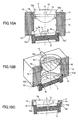
- FIGS. 9A and 11C are diagrams illustrating sixth to eighth embodiments of the lens actuator according to the present invention.
- the drawings of cross-sectional views, perspective views, and enlarged cross-sectional views illustrate a relationship among main elements in the lens actuator, namely, a relationship among the objective lens, diffractive element, and lens holder.
- the diffractive element 3 is installed in a tilted manner so as to prevent flare.
- plane surfaces of end surfaces 12a' in the two protrusions 12 present in a direction orthogonal to a tilted rotation axis (right and left direction in the drawing) among the four protrusion 12 in contact with the outer cylindrical surface of the diffractive element 3, the end surfaces 12a' being in contact with the outer cylindrical surface of the diffractive element 3, are disposed with a shift from the outer cylindrical surface of the diffractive element 3 without tilt such that the outer cylindrical surface of the tilted diffractive element 3 is inscribed and the diffraction pattern center O facing the objective lens 2 corresponds to the optical axis L of the objective lens 2.
- FIGS. 2A and 2B The conventional structure shown in FIGS. 2A and 2B , a tilted cylindrical hole is formed at an installation position of the diffractive element 3, so that it is substantially difficult to manufacture parts taking into consideration required accuracy. However, in the sixth embodiment, manufacturing is readily made.
- the outer cylindrical surface of the diffractive element 3 is inscribed and the cylindrical hole 1a in the direction orthogonal to the rotation axis in the lens holder 1 is formed as tilted.
- the same reference numerals are given to members corresponding to the above-mentioned members and detailed description thereof is omitted.
- the interference prevention structure at corner portions in the fourth embodiment is incorporated. Accordingly, the void portions 1d and 1e are formed on portions in the optical axis L direction of the objective lens 2 in the lens holder 1 in which the end surfaces 12a and the end surfaces 12a' of the protrusions 12 are in contact with the circumferential surfaces of the objective lens 2 and the diffractive element 3 such that the void portion 1d and void portion 1e are not in contact with the objective lens 2 or the diffractive element 3 to perform positioning.
- the same reference numerals are given to members corresponding to the above-mentioned members and detailed description thereof is omitted.
- the plane surface 13 with a small area in the fifth embodiment is incorporated such that the plane surface 13 positions the objective lens 2 and the diffractive element 3 in the optical axis direction.
- FIG. 12 is a diagram schematically showing an optical pickup device on which the objective lens actuator according to the embodiment of the present invention is installed.
- the optical pickup device employs a compatible optical pickup in which the single objective lens 2 disposed on the lens holder 1 performs recording or reproducing with different numerical apertures (NA) on three types of optical storage media (BD, DVD, CD) 20a, 20b, and 20c using different wavelengths of light sources.
- NA numerical apertures
- Substrate thicknesses of the optical storage media 20a, 20b, and 20c of BD, DVD, and CD are 0.1 mm, 0.6 mm, and 1.2 mm, respectively.
- the optical pickup shown in FIG. 12 includes, for the BD optical storage medium 20a, a semiconductor laser 21, collimator lens 22, polarization beam splitter 23, wavelength-selective beam splitter 24, deflection prism 25, 1/4 wave plate 26, aberration correction element (diffractive element) 3, objective lens 2, detection lens 27, and light receiving element 28.
- a central wavelength of the semiconductor laser 21 used as the first light source is 405 nm and the numerical aperture (NA) thereof is 0.85.
- the objective lens 2 and the aberration correction element (diffractive element) 3 constituting the objective lens actuator are disposed on the single lens holder 1 as in each embodiment shown in FIGS. 4A to 11C . Further, the substrate thickness of the BD optical storage medium 20a is 0.1 mm.
- a light emitted from the semiconductor laser 21 is made substantially parallel by the collimator lens 22.
- the light passing through the collimator lens 22 is projected onto the polarization beam splitter 23 and deflected by the deflection prism 25.
- the deflected light is converted to a circular polarized light by the 1/4 wave plate 26 and condensed on the BD optical storage medium 20a via the objective lens 2, thereby performing recording and reproduction of information.
- a light reflected from the BD optical storage medium 20a passes through the 1/4 wave plate 26 and is subsequently converted to a linearly polarized light orthogonal to a polarization direction of the light upon projection on the optical storage medium 20a.
- the converted light is separated into reflected and incident lights by the polarization beam splitter 23 and is deflected.
- the deflected light is introduced on the light receiving element 28 by the detection lens 27, where a reproduction signal, focus error signal, and track error signal are detected and the detected signal become a driving control signal for the drive coil 4 or 5.
- This optical pickup includes a laser unit 30 of two wavelengths emitting a laser beam for the DVD optical storage medium 20b and a laser beam for the CD optical storage medium 20c, so that it is possible to project laser beams having wavelengths different from each other.
- a light emitted to the DVD optical storage medium 20b from a DVD semiconductor laser 30a with a central wavelength of 660 nm passes through a collimator lens 31 and the wavelength-selective beam splitter 24, and the light is deflected by the deflection prism 25.
- the deflected light is condensed on the DVD optical storage medium 20b via the 1/4 wave plate 26, aberration correction element 3, and objective lens 2.
- the substrate thickness of the DVD optical storage medium 20b is 0.6 mm and the numerical aperture (NA) is 0.65. Switching of NA is limited by the aberration correction element 3.
- a light reflected from the DVD optical storage medium 20b passes through the objective lens 2 and the 1/4 wave plate 26 and is subsequently deflected by the wavelength-selective beam splitter 24.
- the deflected light is separated from the incident light by a hologram element 32 and is introduced on a DVD light receiving element 30b, where a reproduction signal, focus error signal, and track error signal are detected.
- a light emitted to the CD optical storage medium 20c from a CD semiconductor laser 33a with a central wavelength of 785 nm passes through the collimator lens 31 and the wavelength-selective beam splitter 24, and the light is deflected by the deflection prism 25.
- the deflected light is condensed on the CD optical storage medium 20c via the 1/4 wave plate 26, aberration correction element 3, and objective lens 2.
- the substrate thickness of the CD optical storage medium 20c is 1.2 mm and the numerical aperture (NA) of the objective lens 2 is 0.50. Switching of NA is limited by the aberration correction element 3.
- a light reflected from the CD optical storage medium 20c passes through the objective lens 2 and the 1/4 wave plate 26 and is subsequently deflected by the wavelength-selective beam splitter 24.
- the deflected light is separated from the incident light by the hologram element 32 and is introduced on a CD light receiving element 33b, where the reproduction signal, focus error signal, and track error signal are detected.
- FIG. 13 is a block diagram schematically showing an optical recording and reproducing apparatus on which the optical pickup device according to the above-mentioned embodiment of the present invention is installed.
- the apparatus performs at least one of reproduction, recording, and deletion of information on an optical storage medium.
- an optical pickup 41 corresponding to the optical pickup shown in FIG. 12 is included.
- the optical recording and reproducing apparatus according to the present embodiment includes a spindle motor 47 rotating the optical storage medium 20, optical pickup 41 used upon recording or reproducing information signals, sending motor 42 moving the optical pickup 41 in an inner circumference and on a circumference of the optical storage medium 20, modulator-demodulator circuit 44 performing predetermined modulation and demodulation processes, servo control circuit 43 performing servo control on the optical pickup 41, and system controller 46 performing control on the entire optical recording and reproducing apparatus.
- the spindle motor 47 is driven by the servo control circuit 43 and is rotated at predetermined rotation numbers.
- the optical storage medium 20 used as recording and reproducing subject is chucked on a driving shaft of the spindle motor 47 and is driven by the servo control circuit 43.
- the optical storage medium 20 is rotated by the spindle motor 47 at the predetermined rotation numbers.
- the optical pickup 41 When the optical pickup 41 records and reproduces information signals on the optical storage medium 20, the optical pickup 41 projects a laser beam onto the rotating optical storage medium 20 and detects a light reflected therefrom as mentioned above.
- the optical pickup 41 is connected to the modulator-demodulator circuit 44.
- the optical pickup 41 records the information signals, signals input from an external circuit 45 and subjected to a predetermined modulation process by the modulator-demodulator circuit 44 are supplied to the optical pickup 41.
- the optical pickup 41 projects a laser beam subjected to optical intensity modulation on the optical storage medium 20.
- the optical pickup 41 reproduces the information signals
- the optical pickup 41 projects a laser beam with a constant output onto the rotating optical storage medium 20 and reproduction signals are generated from a light returning therefrom and the reproduction signals are supplied to the modulator-demodulator circuit 44.
- the optical pickup 41 is connected to the servo control circuit 43.
- the focus servo signal and tracking servo signal are generated from the light reflected by the rotating optical storage medium 20 and returning therefrom as mentioned above. These servo signals are supplied to the servo control circuit 43.
- the modulator-demodulator circuit 44 is connected to the system controller 46 and the external circuit 45. Upon recording the information signals in the optical storage medium 20, the modulator-demodulator circuit 44 receives signals to be recorded in the optical storage medium 20 from the external circuit 45 and performs a predetermined modulation process on the signals under control by the system controller 46.
- the signals modulated by the modulator-demodulator circuit 44 are supplied to the optical pickup 41. Further, upon reproducing the information signals from the optical storage medium 20, the modulator-demodulator circuit 44 receives reproduction signals from the optical pickup 41, the reproduction signals being reproduced from the optical storage medium 20, and performs a predetermined demodulation process on the reproduction signals under control by the system controller 46. Then, the signals demodulated by the modulator-demodulator circuit 44 are output from the modulator-demodulator circuit 44 to the external circuit 45.
- the sending motor 42 moves the optical pickup 41 to a predetermined position in a radial direction of the optical storage medium 20 upon recording and reproducing the information signals.
- the sending motor 42 is moved on the basis of a control signal from the servo control circuit 43.
- the sending motor 42 is connected to the servo control circuit 43 and is controlled by the servo control circuit 43.
- the servo control circuit 43 controls the sending motor 42 such that the optical pickup 41 is moved to the predetermined position facing the optical storage medium 20 under control by the system controller 46.
- the servo control circuit 43 is connected to the spindle motor 47 and controls operation of the spindle motor 47 under control by the system controller 46. In other words, the servo control circuit 43 controls the spindle motor 47 such that the optical storage medium 20 is rotated at predetermined rotation numbers upon recording and reproducing the information signals relative to the optical storage medium 20.
- a method for judging types of optical storage media may use a tracking servo signal or a focus servo signal.
- optical pickup device By employing the optical pickup device according to the present invention in an optical recording and reproducing apparatus performing recording and reproducing processes on plural types of optical storage media, it is possible to improve quality of information recording and reproducing on optical storage media having different substrate thicknesses.
- a lens actuator driving an objective lens condensing a light beam on various types of optical storage media such as CDs, DVDs, and the like, various types of optical pickup devices and optical recording and reproducing apparatuses on which the lens actuator is installed.
- FIG. 14A is a front view showing an embodiment of an optical pickup device on which an objective lens actuator according to the present invention is installed.
- FIG. 14B is a side elevational view showing the embodiment of the optical pickup device on which the objective lens actuator according to the present invention is installed.
- FIG. 14C is a bottom view showing the embodiment of the optical pickup device on which the objective lens actuator according to the present invention is installed.
- the lens holder 1 as a movable unit is a casing holding the objective lens 2 on an upper portion thereof, the objective lens 2 condensing a light beam on an optical disc not shown in the drawings so as to form a beam spot, and also holding the diffractive element 3 as will be described later on a lower portion thereof.
- the drive coil 4 for focusing and the drive coil 5 for tracking are installed on the lens holder 1 and the lens holder 1 is installed on a support block 9 via the support spring 6 functioning as a suspension and a coil feeder line, the support block 9 being disposed on the fixing base 7.
- the magnet 8 functioning as a back yoke in a magnetic circuit is installed on the fixing base 7.
- the drive coils 4 and 5 of the lens holder 1 are disposed and the lens holder 1 is driven in a focusing direction and a tracking direction in accordance with an electromagnetic action of the drive coils 4 and 5 to be energized and the magnet 8.
- FIGS. 15 to 23 are drawings for illustrating embodiments of the lens actuator according to the present invention.
- the drawings of cross-sectional views and perspective views illustrate a relationship among main elements in the lens actuator, namely, a relationship among the objective lens, diffractive element, and lens holder.
- the objective lens 2 is fitted and fixed at an upper end of the lens holder 1 and the diffractive element 3 is fitted and fixed at a lower end of the lens holder 1.
- the fixation of the objective lens 2 and the diffractive element 3 may be performed using a material such as ultraviolet curable resin.
- the diffractive element 3 is installed on the lens holder 1 in a tilted manner so as to prevent degradation of pickup signals due to flare resulting from surface reflection.
- a fitting shaft 3b of the diffractive element 3 is fitted into the cylindrical hole 1a of the lens holder 1 such that the diffracting plane 3a of the diffractive element 3 is tilted relative to the optical axis L of the objective lens 2 and the diffraction pattern center O of the diffracting plane 3a in the diffractive element 3 facing the objective lens 2 substantially corresponds to the optical axis L of the objective lens 2.
- the diffractive element 3 has a discoid shape including a circumferential surface used as the fitting shaft 3b and a plane surface 3c on a top surface side thereof.
- an internal surface is extended in a tilted manner relative to the optical axis L of the objective lens 2.
- the lens holder 1 further includes the cylindrical hole 1a into which the fitting shaft 3b of the diffractive element 3 is fitted and a tilted plane surface 1f tilted relative to a virtual surface perpendicular to the optical axis L of the objective lens 2 inside the cylindrical hole 1a and in contact with the plane surface 3c of the diffractive element 3.
- the diffracting plane 3a of the diffractive element 3 it is possible to prevent flare resulting from surface reflection by installing the diffracting plane 3a of the diffractive element 3 in a tilted manner relative to the objective lens 2 rather than in a perpendicular manner. And it is possible to obtain preferable optical characteristics with reduced aberration by making the diffraction pattern center O in the diffractive element 3 facing the objective lens 2 substantially correspond to the optical axis L of the objective lens 2.
- the cylindrical hole 1a corresponding to the fitting shaft 3b as an outer shape of the diffractive element 3 is formed in the lens holder 1, the cylindrical hole 1a having an axis of tilt L1 which has the same tilt as that of the diffracting plane 3a relative to the optical axis L of the objective lens 2.
- a method of forming in which a different movable metal mold is used only for the tilted hole for example.
- this method has limitation in terms of a structure size.
- the lens holder 1 is formed with a cylindrical hole structure having a central axis parallel with the optical axis L of the objective lens 2 without forming the cylindrical hole 1a in the lens holder 1, the cylindrical hole 1a having the axis of tilt L1 as in the ninth embodiment.
- the diffractive element 3 having a general ring-belt diffraction pattern when an entire shape is formed into a columnar shape in terms of positioning through fitting into the lens holder 1 and readiness of manufacturing of the diffractive element 3 per se, by tilting the diffractive element 3 as mentioned above, in a virtual surface S perpendicular to the optical axis L of the objective lens 2, a projected shape similar to an ellipse is observed shown as shown in FIG. 16 .
- the cylindrical hole 1a having a cylindrical surface whose diameter is defined by a maximum width D of the projected shape of the diffractive element 3 shown in FIG. 16 is formed such that the central axis thereof is coaxial with the optical axis L of the objective lens 2 in the lens holder 1.
- the diffractive element 3 has a discoid shape including a circumferential surface used as the fitting shaft 3b and the plane surface 3c on a top surface side thereof.
- an internal surface is extended in parallel with the optical axis L of the objective lens 2.
- the lens holder 1 includes the cylindrical hole 1a into which the fitting shaft 3b of the diffractive element 3 is fitted in a tilted manner and the tilted plane surface 1f tilted relative to the virtual surface S perpendicular to the optical axis L of the objective lens 2 inside the cylindrical hole 1a and in contact with the plane surface 3c of the diffractive element 3.
- the cylindrical hole 1a is formed into a circular hole on cross section which is readily processed and has no tilted axis, so that there is no problem in forming the lens holder 1. Further, high-accuracy positioning is expected in a direction of a maximum width on the tilted side of the tilted diffractive element 3 by fitting the diffractive element 3 into an inner diameter of the lens holder 1.
- the structure of the tenth embodiment has two problems.
- the maximum projection width of the diffractive element 3 in the fitting shaft 3b in the optical axis L of the objective lens 2, the diffractive element 3 being tilted relative to the optical axis L of the objective lens 2, is defined by a distance between two points of an upper left corner a and a lower right corner b shown in FIG. 17 .
- the diffractive element 3 is rotated on a middle point of the two points of the maximum projection width and the diffractive element 3 is tilted. Accordingly, when the middle point does not correspond to the center of the diffraction pattern center O in the diffractive element 3 facing the objective lens 2, generation of aberration may be increased due to this eccentricity.
- the cylindrical hole 1a of the lens holder 1 is a circular hole and a diameter of an entire circumference is the same as the maximum width, so that the diameter is increased in a direction where the maximum projection width is not changed.
- the diffractive element 3 is fitted into the lens holder 1, clearance fit is used taking into consideration an influence of optical distortion, so that tolerance allowed for clearance is required. In accordance with this, high-accuracy positioning is difficult in a direction where the maximum projection width is not changed.
- An eleventh embodiment shown in FIG. 18 is an example of a structure for dealing with the first problem.
- a central axis L2 of the cylindrical hole 1a having the cylindrical surface whose diameter is defined by the maximum width D of the projected shape of the diffractive element 3 described in the tenth embodiment is disposed on the lens holder 1 such that the central axis L2 is not coaxial with the optical axis L of the objective lens 2 of the lens holder 1 but is shifted in a parallel manner for eccentricity.
- a twelfth embodiment shown in FIG. 19 is an example of a structure for dealing with the first problem in the tenth embodiment.
- the diffracting plane 3a of the diffractive element 3 facing the objective lens 2 is disposed on a plane surface passing through the middle point between the two points (a-b) defining the maximum projection width in the fitting shaft 3b of the diffractive element 3 tilted relative to the optical axis L of the objective lens 2 by bringing the diffractive element 3 into contact with the tilted plane surface 1f of the lens holder 1.
- a thirteenth embodiment shown in FIG. 20 is an example of a structure for dealing with the second problem in the tenth embodiment.
- the outer shape of the diffractive element 3 when tilted relative to the virtual surface perpendicular to the optical axis L of the objective lens 2 is formed such that a long hole shape elongated in accordance with a circular shape having the maximum projection width on the virtual surface (in A direction in FIG.
- the 21 has a hole shape of the cylindrical hole 1a of the lens holder 1 (M size in a longitudinal direction).
- M size in a longitudinal direction By forming the outer shape of the diffractive element 3 in this manner, in the direction where the diffractive element 3 is not tilted (direction orthogonal to the A direction), no clearance is generated between the cylindrical hole 1a and the fitting shaft 3b while obtaining a width of the cylindrical hole 1a in the direction where the diffractive element 3 is tilted in the same manner as in the tenth embodiment.
- a fourteenth embodiment shown in FIG. 22 the example of a structure for dealing with the first problem in the tenth embodiment is applied to the thirteenth embodiment.
- the central axis L2 of the cylindrical hole 1a having a long hole shape is disposed on the lens holder 1 such that the central axis L2 is not coaxial with the optical axis L of the objective lens 2 of the lens holder 1 but is shifted in a parallel manner for eccentricity.
- the example of a structure for dealing with the first problem in the tenth embodiment is applied to the thirteenth embodiment.
- the diffracting plane 3a of the diffractive element 3 facing the objective lens 2 is disposed on the plane surface passing through the middle point between the two points (a-b) defining the maximum projection width.
- the hole shape of the cylindrical hole 1a of the lens holder 1 has a long hole shape.
- a maximum size projected on the virtual surface perpendicular to the optical axis L of the objective lens 2 in the fitting shaft 3b of the diffractive element 3 may be used as a major axis and the outer shape of the diffractive element 3 may be used as a minor axis so as to have an elliptical hole shape.
- a central axis of the elliptical hole shape of the cylindrical hole 1a is set to be coaxial with the optical axis L of the objective lens 2.
- the hole shape of the cylindrical hole 1a of the lens holder 1 is formed to have such an elliptical hole shape as described above, it is possible to deal with the above-mentioned first and second problems by disposing the central axis of the cylindrical hole 1a having an elliptical hole shape is disposed on the lens holder 1 such that the central axis is not coaxial with the optical axis of the objective lens 2 of the lens holder 1 but is shifted in a parallel manner for eccentricity in the same manner as in the fourteenth embodiment or by disposing the diffracting plane 3a of the diffractive element 3 facing the objective lens 2 on the plane surface passing through the middle point between the two points (a-b) defining the maximum projection width in the same manner as in the fifteenth embodiment.
- FIG. 24 is a diagram schematically showing an optical pickup device on which the objective lens actuator according to the embodiment of the present invention is installed.
- the optical pickup device employs a compatible optical pickup in which the single objective lens 2 disposed on the lens holder 1 performs recording or reproducing with different numerical apertures (NA) on three types of optical storage media (BD, DVD, CD) 20a, 20b, and 20c using different wavelengths of light sources.
- NA numerical apertures
- Substrate thicknesses of the optical storage media 20a, 20b, and 20c of BD, DVD, and CD are 0.1 mm, 0.6 mm, and 1.2 mm, respectively.
- the optical pickup shown in FIG. 24 includes, for the BD optical storage medium 20a, a semiconductor laser 21, collimator lens 22, polarization beam splitter 23, wavelength-selective beam splitter 24, deflection prism 25, 1/4 wave plate 26, aberration correction element (diffractive element) 3, objective lens 2, detection lens 27, and light receiving element 28.
- a central wavelength of the semiconductor laser 21 used as the first light source is 405 nm and the numerical aperture (NA) thereof is 0.85.
- the objective lens 2 and the aberration correction element (diffractive element) 3 constituting the objective lens actuator are disposed on the single lens holder 1 as in each embodiment shown in FIGS. 15 to 23 . Further, the substrate thickness of the BD optical storage medium 20a is 0.1 mm.
- a light emitted from the semiconductor laser 21 is made substantially parallel by the collimator lens 22.
- the light passing through the collimator lens 22 is projected onto the polarization beam splitter 23 and deflected by the deflection prism 25.
- the deflected light is converted to a circular polarized light by the 1/4 wave plate 26 and condensed on the BD optical storage medium 20a via the objective lens 2, thereby performing recording and reproduction of information.
- a light reflected from the BD optical storage medium 20a passes through the 1/4 wave plate 26 and is subsequently converted to a linearly polarized light orthogonal to a polarization direction of the light upon projection on the optical storage medium 20a.
- the converted light is separated into reflected and incident lights by the polarization beam splitter 23 and is deflected.
- the deflected light is introduced on the light receiving element 28 by the detection lens 27, where a reproduction signal, focus error signal, and track error signal are detected and the detected signal become a driving control signal for the drive coil 4 or 5.
- This optical pickup includes a laser unit 30 of two wavelengths emitting a laser beam for the DVD optical storage medium 20b and a laser beam for the CD optical storage medium 20c, so that it is possible to project laser beams having wavelengths different from each other.
- a light emitted to the DVD optical storage medium 20b from a DVD semiconductor laser 30a with a central wavelength of 660 nm passes through a collimator lens 31 and the wavelength-selective beam splitter 24, and the light is deflected by the deflection prism 25.
- the deflected light is condensed on the DVD optical storage medium 20b via the 1/4 wave plate 26, aberration correction element 3, and objective lens 2.
- the substrate thickness of the DVD optical storage medium 20b is 0.6 mm and the numerical aperture (NA) is 0.65. Switching of NA is limited by the aberration correction element 3.
- a light reflected from the DVD optical storage medium 20b passes through the objective lens 2 and the 1/4 wave plate 26 and is subsequently deflected by the wavelength-selective beam splitter 24.
- the deflected light is separated from the incident light by a hologram element 32 and is introduced on a DVD light receiving element 30b, where a reproduction signal, focus error signal, and track error signal are detected.
- a light emitted to the CD optical storage medium 20c from a CD semiconductor laser 33a with a central wavelength of 785 nm passes through the collimator lens 31 and the wavelength-selective beam splitter 24, and the light is deflected by the deflection prism 25.
- the deflected light is condensed on the CD optical storage medium 20c via the 1/4 wave plate 26, aberration correction element 3, and objective lens 2.
- the substrate thickness of the CD optical storage medium 20c is 1.2 mm and the numerical aperture (NA) of the objective lens 2 is 0.50. Switching of NA is limited by the aberration correction element 3.
- a light reflected from the CD optical storage medium 20c passes through the objective lens 2 and the 1/4 wave plate 26 and is subsequently deflected by the wavelength-selective beam splitter 24.
- the deflected light is separated from the incident light by the hologram element 32 and is introduced on a CD light receiving element 33b, where the reproduction signal, focus error signal, and track error signal are detected.
- FIG. 13 is a block diagram schematically showing an optical recording and reproducing apparatus on which the optical pickup device according to the above-mentioned embodiment of the present invention is installed.
- the apparatus performs at least one of reproduction, recording, and deletion of information on an optical storage medium.
- an optical pickup 41 corresponding to the optical pickup shown in FIG. 24 is included.
- the optical recording and reproducing apparatus according to the present embodiment includes a spindle motor 47 rotating the optical storage medium 20, optical pickup 41 used upon recording or reproducing information signals, sending motor 42 moving the optical pickup 41 in an inner circumference and on a circumference of the optical storage medium 20, modulator-demodulator circuit 44 performing predetermined modulation and demodulation processes, servo control circuit 43 performing servo control on the optical pickup 41, and system controller 46 performing control on the entire optical recording and reproducing apparatus.
- the spindle motor 47 is driven by the servo control circuit 43 and is rotated at predetermined rotation numbers.
- the optical storage medium 20 used as recording and reproducing subject is chucked on a driving shaft of the spindle motor 47 and is driven by the servo control circuit 43.
- the optical storage medium 20 is rotated by the spindle motor 47 at the predetermined rotation numbers.
- the optical pickup 41 When the optical pickup 41 records and reproduces information signals on the optical storage medium 20, the optical pickup 41 projects a laser beam onto the rotating optical storage medium 20 and detects a light reflected therefrom as mentioned above.
- the optical pickup 41 is connected to the modulator-demodulator circuit 44.
- the optical pickup 41 records the information signals, signals input from an external circuit 45 and subjected to a predetermined modulation process by the modulator-demodulator circuit 44 are supplied to the optical pickup 41.
- the optical pickup 41 projects a laser beam subjected to optical intensity modulation on the optical storage medium 20.
- the optical pickup 41 reproduces the information signals
- the optical pickup 41 projects a laser beam with a constant output onto the rotating optical storage medium 20 and reproduction signals are generated from a light returning therefrom and the reproduction signals are supplied to the modulator-demodulator circuit 44.
- the optical pickup 41 is connected to the servo control circuit 43.
- the focus servo signal and tracking servo signal are generated from the light reflected by the rotating optical storage medium 20 and returning therefrom as mentioned above. These servo signals are supplied to the servo control circuit 43.
- the modulator-demodulator circuit 44 is connected to the system controller 46 and the external circuit 45. Upon recording the information signals in the optical storage medium 20, the modulator-demodulator circuit 44 receives signals to be recorded in the optical storage medium 20 from the external circuit 45 and performs a predetermined modulation process on the signals under control by the system controller 46.
- the signals modulated by the modulator-demodulator circuit 44 are supplied to the optical pickup 41. Further, upon reproducing the information signals from the optical storage medium 20, the modulator-demodulator circuit 44 receives reproduction signals from the optical pickup 41, the reproduction signals being reproduced from the optical storage medium 20, and performs a predetermined demodulation process on the reproduction signals under control by the system controller 46. Then, the signals demodulated by the modulator-demodulator circuit 44 are output from the modulator-demodulator circuit 44 to the external circuit 45.
- the sending motor 42 moves the optical pickup 41 to a predetermined position in a radial direction of the optical storage medium 20 upon recording and reproducing the information signals.
- the sending motor 42 is moved on the basis of a control signal from the servo control circuit 43.
- the sending motor 42 is connected to the servo control circuit 43 and is controlled by the servo control circuit 43.
- the servo control circuit 43 controls the sending motor 42 such that the optical pickup 41 is moved to the predetermined position facing the optical storage medium 20 under control by the system controller 46.
- the servo control circuit 43 is connected to the spindle motor 47 and controls operation of the spindle motor 47 under control by the system controller 46. In other words, the servo control circuit 43 controls the spindle motor 47 such that the optical storage medium 20 is rotated at predetermined rotation numbers upon recording and reproducing the information signals relative to the optical storage medium 20.
- a method for judging types of optical storage media may use a tracking servo signal or a focus servo signal.
- optical pickup device By employing the optical pickup device according to the present invention in an optical recording and reproducing apparatus performing recording and reproducing processes on plural types of optical storage media, it is possible to improve quality of information recording and reproducing on optical storage media having different substrate thicknesses.
- a lens actuator driving an objective lens condensing a light beam on various types of optical storage media such as CDs, DVDs, and the like, various types of optical pickup devices and optical recording and reproducing apparatuses on which the lens actuator is installed.
Landscapes
- Physics & Mathematics (AREA)
- Optics & Photonics (AREA)
- Optical Head (AREA)
Applications Claiming Priority (3)
| Application Number | Priority Date | Filing Date | Title |
|---|---|---|---|
| JP2007022752A JP2008192203A (ja) | 2007-02-01 | 2007-02-01 | レンズアクチュエータおよび光ピックアップ装置ならびに光学式記録/再生装置 |
| JP2007025208A JP2008192231A (ja) | 2007-02-05 | 2007-02-05 | レンズアクチュエータおよび光ピックアップ装置ならびに光学式記録/再生装置 |
| JP2007051143A JP2008217863A (ja) | 2007-03-01 | 2007-03-01 | レンズアクチュエータおよび光ピックアップ装置ならびに光学式記録/再生装置 |
Publications (2)
| Publication Number | Publication Date |
|---|---|
| EP1953746A2 true EP1953746A2 (fr) | 2008-08-06 |
| EP1953746A3 EP1953746A3 (fr) | 2009-11-04 |
Family
ID=39345227
Family Applications (1)
| Application Number | Title | Priority Date | Filing Date |
|---|---|---|---|
| EP08250205A Withdrawn EP1953746A3 (fr) | 2007-02-01 | 2008-01-16 | Actionneur optique, dispositif de capture optique et enregistrement optique et appareil de reproduction |
Country Status (2)
| Country | Link |
|---|---|
| US (1) | US7979872B2 (fr) |
| EP (1) | EP1953746A3 (fr) |
Families Citing this family (3)
| Publication number | Priority date | Publication date | Assignee | Title |
|---|---|---|---|---|
| KR20090059108A (ko) * | 2006-08-30 | 2009-06-10 | 닛끼 가부시끼가이샤 | 프로필렌의 제조방법 및 프로필렌의 제조장치 |
| JP5020587B2 (ja) * | 2006-09-28 | 2012-09-05 | 日揮株式会社 | プロピレンの製造方法およびプロピレンの製造装置 |
| CN101750205B (zh) * | 2008-12-10 | 2012-05-30 | 鸿富锦精密工业(深圳)有限公司 | 镜片偏心检测装置 |
Citations (2)
| Publication number | Priority date | Publication date | Assignee | Title |
|---|---|---|---|---|
| JPH08315393A (ja) | 1995-05-18 | 1996-11-29 | Matsushita Electric Ind Co Ltd | 光ピックアップ用対物レンズ駆動装置 |
| JP2006139874A (ja) | 2004-11-12 | 2006-06-01 | Konica Minolta Opto Inc | レンズユニット、及び光ピックアップ装置 |
Family Cites Families (16)
| Publication number | Priority date | Publication date | Assignee | Title |
|---|---|---|---|---|
| JPH11352374A (ja) * | 1998-06-08 | 1999-12-24 | Olympus Optical Co Ltd | レンズの保持構造 |
| US6834036B1 (en) * | 1998-10-28 | 2004-12-21 | Matsushita Electric Industrial Co., Ltd. | Optical head for a plurality of types of information recording media |
| US6594204B1 (en) * | 1999-03-31 | 2003-07-15 | Sony Corporation | Lens holder, method for manufacturing lens holder, metal die for producing lens holder and objective lens device |
| JP4224654B2 (ja) * | 1999-06-17 | 2009-02-18 | 旭硝子株式会社 | 光ヘッド装置 |
| JP3710038B2 (ja) * | 1999-07-02 | 2005-10-26 | 株式会社リコー | レンズアクチュエータ及び光ディスク記録再生装置 |
| JP4584382B2 (ja) * | 1999-09-06 | 2010-11-17 | 株式会社リコー | 光ピックアップ装置 |
| US6704255B2 (en) * | 2000-08-22 | 2004-03-09 | Ricoh Company, Ltd. | Lens actuator |
| JP2004185789A (ja) * | 2002-10-08 | 2004-07-02 | Ricoh Co Ltd | レンズアクチュエータ、光ピックアップ装置および光ディスク装置 |
| JP2005235349A (ja) * | 2004-02-23 | 2005-09-02 | Ricoh Co Ltd | アクチュエータ、光ピックアップ装置及び光ディスク装置 |
| KR100601955B1 (ko) * | 2004-06-01 | 2006-07-14 | 삼성전기주식회사 | 집적 광학 시스템 및 그 제조 방법 및 이를 적용한 정보기록 및/또는 재생기기 |
| TW200623094A (en) * | 2004-08-31 | 2006-07-01 | Konica Minolta Opto Inc | Lens unit for optical pick-up apparatus, optical element for optical pick-up apparatus, lens frame for lens unit, assembly method of the lens unit, and optical pick-up apparatus |
| JP2006085837A (ja) * | 2004-09-16 | 2006-03-30 | Konica Minolta Opto Inc | 対物レンズユニット及びこれを用いた光ピックアップ装置 |
| JP4587892B2 (ja) * | 2005-07-01 | 2010-11-24 | 三洋電機株式会社 | レーザー集光装置、光ピックアップ装置、光ディスク記録再生装置 |
| US7570547B2 (en) * | 2005-08-22 | 2009-08-04 | Konica Minolta Opto, Inc. | Objective lens unit and optical pickup device |
| CN102290065A (zh) * | 2005-08-26 | 2011-12-21 | 松下电器产业株式会社 | 物镜驱动装置 |
| JP4539556B2 (ja) * | 2005-12-28 | 2010-09-08 | パナソニック株式会社 | 光ピックアップ装置及び光ディスク装置 |
-
2008
- 2008-01-16 EP EP08250205A patent/EP1953746A3/fr not_active Withdrawn
- 2008-01-30 US US12/022,847 patent/US7979872B2/en not_active Expired - Fee Related
Patent Citations (2)
| Publication number | Priority date | Publication date | Assignee | Title |
|---|---|---|---|---|
| JPH08315393A (ja) | 1995-05-18 | 1996-11-29 | Matsushita Electric Ind Co Ltd | 光ピックアップ用対物レンズ駆動装置 |
| JP2006139874A (ja) | 2004-11-12 | 2006-06-01 | Konica Minolta Opto Inc | レンズユニット、及び光ピックアップ装置 |
Also Published As
| Publication number | Publication date |
|---|---|
| EP1953746A3 (fr) | 2009-11-04 |
| US7979872B2 (en) | 2011-07-12 |
| US20080189727A1 (en) | 2008-08-07 |
Similar Documents
| Publication | Publication Date | Title |
|---|---|---|
| CN100358022C (zh) | 光学头、用于装配透镜的设备和方法 | |
| JP3948028B2 (ja) | 光学ピックアップ及びディスクプレーヤ | |
| US7787340B2 (en) | Optical pickup | |
| KR19990030260A (ko) | 광픽업장치 | |
| KR100522594B1 (ko) | 호환형 광픽업장치 및 이를 채용한 광기록재생장치 | |
| US20060136951A1 (en) | Optical head capable of recording and reproducing information on any one of a plurality of kinds of optical information recording medium and optical information recording and reproducing apparatus using the same | |
| EP1953746A2 (fr) | Actionneur optique, dispositif de capture optique et enregistrement optique et appareil de reproduction | |
| JP4509854B2 (ja) | 対物レンズ駆動装置,光ピックアップ装置および光ディスク装置 | |
| US20080298214A1 (en) | Objective lens actuator utilizing piezoelectric elements | |
| US8938746B2 (en) | Object lens driving device and optical disc drive including the same | |
| JP2004110971A (ja) | 対物レンズ駆動装置、光ピックアップ装置、及び光ディスク装置 | |
| EP1909273B1 (fr) | Tête de lecture optique et son procédé de fabrication. | |
| EP1929472B1 (fr) | Commande destinee a un dispositif de balayage optique | |
| JP3892444B2 (ja) | 対物レンズ駆動装置、およびこれを用いた光ピックアップ装置 | |
| JP2008217863A (ja) | レンズアクチュエータおよび光ピックアップ装置ならびに光学式記録/再生装置 | |
| JP2009004025A (ja) | レンズアクチュエータおよび光ピックアップならびに光学式記録/再生装置 | |
| JP3919171B2 (ja) | 対物レンズ駆動装置およびそれを備える光ピックアップ装置 | |
| JP2005122778A (ja) | 光ピックアップ装置およびそれに備わる球面収差補正部の調整方法 | |
| JP2004055071A (ja) | 光学ピックアップ装置、光学ピックアップ装置の製造方法及び記録再生装置 | |
| JP2008192203A (ja) | レンズアクチュエータおよび光ピックアップ装置ならびに光学式記録/再生装置 | |
| JP2003263759A (ja) | 光学式情報装置 | |
| JP2008192231A (ja) | レンズアクチュエータおよび光ピックアップ装置ならびに光学式記録/再生装置 | |
| JP2006079781A (ja) | 光ピックアップ及びディスクドライブ装置 | |
| JP2008146799A (ja) | レンズアクチュエータおよび光ピックアップ装置ならびに光学式記録/再生装置 | |
| JP2006294118A (ja) | 光学式ピックアップ装置 |
Legal Events
| Date | Code | Title | Description |
|---|---|---|---|
| PUAI | Public reference made under article 153(3) epc to a published international application that has entered the european phase |
Free format text: ORIGINAL CODE: 0009012 |
|
| 17P | Request for examination filed |
Effective date: 20080215 |
|
| AK | Designated contracting states |
Kind code of ref document: A2 Designated state(s): AT BE BG CH CY CZ DE DK EE ES FI FR GB GR HR HU IE IS IT LI LT LU LV MC MT NL NO PL PT RO SE SI SK TR |
|
| AX | Request for extension of the european patent |
Extension state: AL BA MK RS |
|
| PUAL | Search report despatched |
Free format text: ORIGINAL CODE: 0009013 |
|
| AK | Designated contracting states |
Kind code of ref document: A3 Designated state(s): AT BE BG CH CY CZ DE DK EE ES FI FR GB GR HR HU IE IS IT LI LT LU LV MC MT NL NO PL PT RO SE SI SK TR |
|
| AX | Request for extension of the european patent |
Extension state: AL BA MK RS |
|
| AKX | Designation fees paid | ||
| REG | Reference to a national code |
Ref country code: DE Ref legal event code: 8566 |
|
| STAA | Information on the status of an ep patent application or granted ep patent |
Free format text: STATUS: THE APPLICATION IS DEEMED TO BE WITHDRAWN |
|
| 18D | Application deemed to be withdrawn |
Effective date: 20100505 |