EP1953082B1 - Unterseeboot mit einer kabelgeführten Kommunikationsboje - Google Patents
Unterseeboot mit einer kabelgeführten Kommunikationsboje Download PDFInfo
- Publication number
- EP1953082B1 EP1953082B1 EP07024872A EP07024872A EP1953082B1 EP 1953082 B1 EP1953082 B1 EP 1953082B1 EP 07024872 A EP07024872 A EP 07024872A EP 07024872 A EP07024872 A EP 07024872A EP 1953082 B1 EP1953082 B1 EP 1953082B1
- Authority
- EP
- European Patent Office
- Prior art keywords
- submarine
- communication buoy
- arm
- articulated
- carrier
- Prior art date
- Legal status (The legal status is an assumption and is not a legal conclusion. Google has not performed a legal analysis and makes no representation as to the accuracy of the status listed.)
- Active
Links
Images

Classifications
-
- B—PERFORMING OPERATIONS; TRANSPORTING
- B63—SHIPS OR OTHER WATERBORNE VESSELS; RELATED EQUIPMENT
- B63G—OFFENSIVE OR DEFENSIVE ARRANGEMENTS ON VESSELS; MINE-LAYING; MINE-SWEEPING; SUBMARINES; AIRCRAFT CARRIERS
- B63G8/00—Underwater vessels, e.g. submarines; Equipment specially adapted therefor
- B63G8/38—Arrangement of visual or electronic watch equipment, e.g. of periscopes, of radar
-
- B—PERFORMING OPERATIONS; TRANSPORTING
- B63—SHIPS OR OTHER WATERBORNE VESSELS; RELATED EQUIPMENT
- B63G—OFFENSIVE OR DEFENSIVE ARRANGEMENTS ON VESSELS; MINE-LAYING; MINE-SWEEPING; SUBMARINES; AIRCRAFT CARRIERS
- B63G8/00—Underwater vessels, e.g. submarines; Equipment specially adapted therefor
- B63G8/42—Towed underwater vessels
-
- B—PERFORMING OPERATIONS; TRANSPORTING
- B63—SHIPS OR OTHER WATERBORNE VESSELS; RELATED EQUIPMENT
- B63B—SHIPS OR OTHER WATERBORNE VESSELS; EQUIPMENT FOR SHIPPING
- B63B2203/00—Communication means
Definitions
- the invention relates to a submarine according to the features indicated in the preamble of claim 1.
- a buoy is described in the various antennas, sensors and communication means are united.
- This buoy is connected by a cable, which is intended for both data transmission and mechanical connection between buoy and submarine, with the submarine.
- the known device has a winch on the boat side, over which the cable is wound and the buoy is pulled into a funnel-shaped receptacle inside the hull, after which the receptacle is closed by means of a cover.
- equipment carriers For communication buoys of this type devices with arranged in the hull equipment carriers are known in which the equipment carrier can be spent for loading and unloading the buoys in a position outside of the hull.
- the equipment carrier is attached to such devices on a pivot arm with which it can be pivoted through an opening in the outer skin of the submarine to a position outside the hull.
- the attachment of the equipment carrier to the pivoting arm in these devices is typically adapted to the relatively narrow space between the pressure body and the outer skin, that is, the equipment carrier is attached to the pivoting arm in such a way that it finds sufficient space with the communications buoy thereon in that space.
- This favorable for the storage of the communication buoy alignment of the equipment carrier with respect to the swivel arm proves to be particularly problematic when catching the buoy in the pivoted position of the swivel arm and equipment carrier when the open docking area of the equipment wearer not directly facing the buoy to be picked and thus not directly accessible is.
- the submarine according to the invention has a cable-controlled communication buoy, which in the non-active, i. is stored in unused condition in a storage position between the pressure hull and the outer skin in a device carrier.
- a storage position here is preferably provided a position below an upper deck at the rear of the tower of the submarine.
- the device carrier is attached to at least one pressure arm side articulated arm.
- a pressure-body-side articulation of the pivot arm is understood to mean both a direct articulated mounting of the pivot arm on the pressure body and an articulation of the pivot arm on a component connected to the pressure body or an assembly.
- the swivel arm of the equipment carrier is pivotable by a provided in the outer skin closable opening in a position outside of the outer skin. In this position, the application and retrieval of the communication buoy is carried out in the usual way by unwinding or winding the guide cable from or to a winch.
- the device carrier is not rigidly attached to the pivot arm but pivotally mounted on it.
- the aim of this embodiment is to be able to change the position of the device carrier relative to the pivot arm in different pivot positions of the pivot arm, so that the device carrier both in the storage position and in the position outside of the outer skin can be aligned by pivoting so that its orientation in the storage position takes into account the limited space available there, while its orientation in the outer position is adapted to the deployment and retrieval of the communication buoy.
- the invention For pivoting the device carrier relative to the swivel arm, the invention provides coupling means for coupling the pivoting movement of the swivel arm with a pivoting movement of the device carrier about the swivel arm.
- these coupling means is preferably a pivoting movement of the pivot arm about its pressure-side swivel joint simultaneously transferred into a pivoting movement of the device carrier to the swivel arm, the device carrier undergoes a superposition of these pivotal movements.
- a superposition of the two pivotal movements is desired, in which, when pivoting the pivot arm, although the distance of the device carrier from the pressure body changes, but the orientation of the device carrier relative to the pressure body remains substantially the same.
- coupling means is advantageously provided at least one link, which is articulated on both the pressure body side and device carrier side.
- the link is the pressure body side spaced from the articulated mounting of the pivot arm and device carrier side pivotally mounted at a distance from the articulated connection of the swing arm and equipment rack.
- the articulation of the link to the pressure body and equipment carrier is in this case such that the swivel arm and the handlebar are pivotable in a common plane.
- the distance of the pressure-body side and device carrier-side articulation points of the swing arm and handlebar is basically arbitrary, but is preferred a configuration in which the points of articulation of the swing arm and handlebar to pressure hull and equipment rack substantially have the same distance, so that the handlebar is guided substantially parallel to the pivot arm.
- a pressure-side arranged linear drive is preferably provided, which is operatively connected to the pivot arm.
- This linear drive expediently engages on the pivot arm essentially transversely to its longitudinal extent.
- the type of linear drive used is basically freely selectable. For example, the use of a threaded spindle as a linear drive for pivoting the pivot arm is conceivable.
- the linear drive is particularly advantageously formed by a lifting cylinder.
- an embodiment of the hoist cylinder is preferred as a double-acting hydraulic cylinder, with which it is possible, not only the force required during pivoting of the pivot arm lifting force but also the buoyancy force of the communication buoy opposing force when catching the buoy or when swinging to exercise the swivel arm.
- the device carrier is advantageously mounted elastically on the pressure hull of the submarine.
- the elastic and shock-proof storage of the equipment carrier is preferably carried out indirectly, for example by elastic mounting of the swivel arm.
- the pressure-body-side joint on which the pivot arm is pivotally mounted be disposed on a foundation, which in turn is arranged on the pressure body, being provided between the foundation and the pressure body spring and / or damping elements are.
- At least one guide roller for guiding the guide cable is provided on the device carrier.
- the guide roller is preferably arranged on the side of the device carrier, which faces the arranged on the pressure hull winch for removal and insertion of the guide cable. Between the winch and the equipment carrier, it forms a deflection roller by means of which the alignment of the guide cable from a first direction on the windage side of the equipment carrier is deflected in a second direction on the side of the device carrier.
- a hollow guide body is arranged on the communication buoy facing side of the device carrier. Through this guide body, the guide cable of the communication buoy is guided.
- the guide body expediently has a shape which corresponds to the shape of the communication buoy in the region of its guide cable connection.
- the communication buoy where the guide cable is fastened to it, has a pointed nose, which tapers in the direction of the connection of the guide cable essentially to the cable diameter. Accordingly, the guide body has a funnel shape complementary thereto.
- a pressure arm side hinged support arm is provided. This is for fixing the communication buoy in the storage position in a communication buoy encompassing position movable.
- the joint on which the holding arm is pivotally mounted on the pressure body side is preferably arranged together with the joint, on which the pivot arm is pivotably mounted, on a common base mounted elastically on the pressure body.
- a toggle lever For pivoting the support arm, a toggle lever is preferably provided, which has a first lever arm hinged arm and a second pressure body side applied lever.
- a linear actuator applied on the pressure side preferably a lifting cylinder, engages the knee joint of the toggle lever which connects these levers.
- the knee joint assembly has the advantage that it is automatically locked in the extended end position.
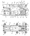
- FIG. 1 shows the submarine 2 according to the invention in the submerged state below the water surface 4.
- a gear tray 6 is extended for a communication buoy 8 by a rear side of the tower 10 of the submarine 2 arranged opening of the outer skin in a position outside of this outer skin.
- the communication buoy 8 is shown floating in its deployed state on the water surface 4.
- the communication buoy 8 is connected to a guide cable 12, which has been drained from a wind inside the boat, which is not shown in the figures.
- the communication buoy 8 with the submarine 2 is both mechanically and data-connected.
- the communication buoy 8 is shown in the equipment carrier 6 in the storage position in the boat interior between the pressure hull 14 and outer skin 16 of the submarine 2.
- the communication buoy 8 is arranged in the storage position essentially below an opening of the outer skin 16, which is closed by two flaps 18 pivotable parallel to one another and a flap 20 which can be pivoted by 90 ° relative to the axes of rotation of these flaps 18.
- Below the flaps 18 and 20 16 hydraulically actuated linear cylinder 22 are arranged on the underside of the outer skin, with which the flaps 18 and 20 can be pivoted into a position releasing the outer skin opening position.
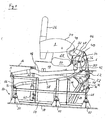
- the communication buoy 8 has a floating body 24, on whose upper side an antenna body 26 for receiving various receiving and transmitting antennas and sensors of the communication buoy 8 are arranged.
- the antenna body 26 is formed foldable and can in the storage position of the communication buoy 8 in a voltage applied to the float 24 position ( FIGS. 2 and 3 ) and how in FIG. 4 shown, folded into a functional position in which the antenna body 26 is substantially upright on the float 24.
- a keel sword 28 is arranged, which has at its end a cross-sectional widening 30 in the form of a keel fin as ballast.
- the keel sword 28 forms a guide nose 32, which extends substantially transversely to the orientation of the keel sword 28 forward.
- this guide nose 32 is in the FIGS. 2 to 6 not shown guide cable 12 of the communication buoy 8 attached.
- the device carrier 6 has a carrier frame which is formed by two carrier components 34, which are arranged spaced apart rigidly on a shaft 36.
- the carrier components 34 are identical. They have a Y-shape in which three arms 38, 40 and 42 extend outwardly from a central area through which the shaft 36 passes.
- a guide roller 35 is rotatably mounted on the shaft 36 via the one in the Fig. 2 to 5 not shown guide cable 12 is guided and is deflected there.
- a receptacle 44 for the communication buoy 8 is attached.
- This receptacle 44 has an outer contour which corresponds to the contour of the communication buoy 8 in the region of the keel blade 28 below the guide nose 32 and the cross-sectional widening 30.
- the communication buoy 8 is supported by the cross-sectional enlargement 30 and the keel sword 28 on the receptacle 44.
- a guide member 46 is arranged, which forms a funnel-like tapering in the direction of the support members 34 guide channel, which corresponds to the guide nose 32 of the communication buoy 8.
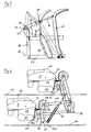
- the pivot arms 48 of the equipment carrier 6 is connected to the pressure body 14.
- the pivot arms 48 are not disposed directly on the pressure body 14 of the submarine 2 but pivotally mounted on a frame 50 which is connected via six spring elements 52 to the pressure body 14.
- the frame 50 has, as out Fig. 3 It can be seen, a rectangular frame 54 which is elastically mounted on the spring elements 52 so that the frame 54 is spaced from the pressure body 14, whereby the frame 50 with the connected thereto via the pivot arms 48 equipment carrier 6 and, consequently, in the Device carrier 6 mounted communication buoy 8 in the event of a shock, for example, caused by an explosion shock stress within certain limits and are therefore stored shock-proof.
- the pivot arms 48 are pivotally mounted about an axis A at the ends of two posts 56 which extend on one side of the frame 54 in the region of the corner points normal to the areal extent of the frame in the direction of the outer skin 16.
- the tool carrier 6 is connected via the shaft 36 to the free ends of the pivot arms 48, wherein the shaft 36 connects these ends of the pivot arms 48.
- the shaft 36 is freely rotatably mounted on the pivot arms 48, whereby the equipment carrier 6 is pivotable about an axis formed by the shaft 36 relative to the pivot arms 48.
- the links 58 are pivotable on the frame 50 about an axis B.
- the ends of the links 58 are each articulated at one end of the arms 42 of the support members 34.
- the distance of the articulation points of the links 58 on the arms 42 of the shaft 36 substantially corresponds to the distance of the frame-side articulation points of pivot arms 48 and links 58, so that the links 58 are guided substantially parallel to the pivot arms 48.
- a double-acting hydraulic cylinder 60 is provided, which is arranged on the frame 54 of the frame 50 and thus also shock-proof stored.
- An extendable piston rod 62 of the hydraulic cylinder 60 is articulated via a connecting member 64 on one of the pivot arms 48.
- two support arms 66 are hinged to the frame 54 of the frame.
- the free ends of these support arms 66 are angled in the direction of the device carrier 6, wherein the device carrier 6 facing contour of the support arm 66 in this area is complementary to the outer contour of the float 24 of the communication buoy 8.
- the support arms 66 can be pivoted such that their angled areas the float 24 of the in the storage position ( Fig. 1 and 2 ) between the pressure body 14 and outer skin 16 located communication buoy 8, so that the communication buoy 8 is positively fixed between the receptacle 44 of the equipment carrier 6 and the support arms 66.
- the cross strut 70 carries two bearings 72, in which a Shaft 74 is mounted rotatably. On the shaft 74 on the outside of the bearing 72 each have a toggle lever 76 is articulated.
- the knee levers 76 each have a first lever part 78, which is connected via a hinge 80 with a second lever part 82.
- the lever member 78 is attached to the shaft 74 while the lever member 82 is hinged to the support arm 66.
- a double-acting hydraulic cylinder 84 is provided for actuating the retaining arms 66. This does not attack directly on the knee lever 76. Instead, a lever 86 is provided, which is articulated both on the extendable piston rod 88 of the hydraulic cylinder 84 and on the joint 80 of the toggle lever 76.
- the communication buoy 8 is first stored in the storage position between the pressure body 14 and outer skin 18 in the equipment carrier 6. In doing so, the communication buoy 8 in the equipment carrier 6 assumes a position which essentially corresponds to the floating position.
- the dispensing operation of the communication buoy 8 begins by unfolding the outer skin opening closing flaps 18 and 20 by means of the linear cylinder 22.
- the guide cable 12 is held taut by the unillustrated winch to which the guide cable 12 is connected.
- the guide nose 32 of the communication buoy 8 is firmly pulled in the formed on the guide member 46 guide channel and the keel blade 28 with the arranged cross-sectional enlargement 30 of the communication buoy 8 firmly against the receptacle 44 of the device carrier 6.
- the holding arms 66 are pivoted away from the communication buoy 8 by operation of the hydraulic cylinder 84.
- the hydraulic cylinder 60 By means of the hydraulic cylinder 60 is the swivel arm 48 with the device carrier 6 arranged thereon and the communication buoy 8 located thereon are swung out.
- the end of the pivot arms 48, on which the equipment carrier 6 is articulated, is formed in the direction of the outer skin 16 of the submarine 2 angled. This makes it possible to swivel out the swivel arms 48 only so far that these angled regions of the swivel arms 48 with the device carrier 6 arranged thereon protrude from the outer skin 16. How out Fig. 4 can be seen, the pivot arms 48 are suitably dimensioned so that they protrude in the swung-out state only in the region of the skin opening, which is otherwise closed by the flap 20. This makes it possible, after the deployment of the communication buoy 8 at least close the flaps 18 again, resulting in a signature improvement of the submarine 2 when deployed communication buoy 8.
- the recovery of the communication buoy 8 is carried out by winding the guide cable 12 on the wind provided for this, until the at the Medunikationsboje 8 trained guide nose 32 is caught in the guide channel of the guide member 46 and pulled in the equipment rack 6 in a storage position. Subsequently, the flaps 18 are opened again on the outer skin 16 and the pivot arms 48 are pivoted with the equipment carrier 6 into the intermediate space between the pressure body 14 and the outer skin 16. In the storage position, the holding arms 66 are pivoted into a position encompassing the floating body 24 of the communication buoy 8, so that the communication buoy is fixed. Now, the guide cable 12 is relieved of strain and the flaps 18 and 20 are closed on the outer skin 16.
- Fig. 6 shows a further embodiment of a device support 6 'for the submarine according to the invention 2.
- This equipment carrier 6' has a support frame, which is formed by two substantially Y-shaped support members 34 ', which are spaced from each other rigidly mounted on a shaft. Starting from the connection of the carrier components 34 'on the shaft, three arms 90, 92 and 94 extend outwards. At the ends of the arms 94 of the two support members 34 ', a receptacle 44' for the communication buoy 8 is attached.
- This receptacle 44 ' also forms a guide component with a funnel-shaped guide channel formed thereon for receiving the guide nose 32 formed on the communication buoy 8.
- two pairs of pivot arms 98 and 100 are pivotably mounted on a foundation 96 so as to be pivotally spaced from one another, wherein the pivot arms 98 and 100 have a common pivot plane.
- the ends of the pivot arms 98 are hinged to the shaft connecting the support members 34 '.
- a guide roller 102 is freely rotatably mounted between the pivot arms 98.
- the ends of the pivot arms 100 are hinged to a shaft connecting the ends of the arms 90, wherein on this shaft also a freely rotatable Guide roller 104 is arranged.
- the pivot arms 98 are actuated by means of a double-acting hydraulic cylinder 60 ', which acts on one of the pivot arms 100 via a connecting component 64'.
- the pairs of pivot arms 98 and 100 are arranged to form a parallelogram guide in which one of the pivot arms 98, 100 forms a link parallel to the other pivot arm 98, 100, allowing the implement carrier 6 'and the communication buoy thereon without changing their orientation to the pressure body 14 off or swing.
Landscapes
- Engineering & Computer Science (AREA)
- Mechanical Engineering (AREA)
- Aviation & Aerospace Engineering (AREA)
- Radar, Positioning & Navigation (AREA)
- Laying Of Electric Cables Or Lines Outside (AREA)
- Communication Cables (AREA)
Applications Claiming Priority (1)
| Application Number | Priority Date | Filing Date | Title |
|---|---|---|---|
| DE102007005460A DE102007005460B3 (de) | 2007-02-03 | 2007-02-03 | Unterseeboot |
Publications (2)
| Publication Number | Publication Date |
|---|---|
| EP1953082A1 EP1953082A1 (de) | 2008-08-06 |
| EP1953082B1 true EP1953082B1 (de) | 2009-11-11 |
Family
ID=39134761
Family Applications (1)
| Application Number | Title | Priority Date | Filing Date |
|---|---|---|---|
| EP07024872A Active EP1953082B1 (de) | 2007-02-03 | 2007-12-21 | Unterseeboot mit einer kabelgeführten Kommunikationsboje |
Country Status (5)
| Country | Link |
|---|---|
| EP (1) | EP1953082B1 (es) |
| KR (1) | KR101160886B1 (es) |
| AT (1) | ATE448138T1 (es) |
| DE (2) | DE102007005460B3 (es) |
| ES (1) | ES2334069T3 (es) |
Families Citing this family (6)
| Publication number | Priority date | Publication date | Assignee | Title |
|---|---|---|---|---|
| DE102009025111B3 (de) | 2009-06-11 | 2010-12-16 | Howaldtswerke-Deutsche Werft Gmbh | Unterseeboot |
| DE102009032138A1 (de) * | 2009-07-08 | 2011-01-13 | Gabler Maschinenbau Gmbh | Vorrichtung zum Aus- und Einbringen eines kabelgebundenen Schleppkörpers aus einem oder in ein Unterseeboot im getauchten Zustand |
| KR101403790B1 (ko) * | 2012-09-19 | 2014-06-03 | (주)보고 | 수면하에서 sdv 분리를 위한 소형잠수함 |
| IL228688B (en) * | 2013-10-02 | 2018-05-31 | Elta Systems Ltd | Mast system and method for operating a mast system |
| CN103552676B (zh) * | 2013-11-15 | 2015-10-07 | 河南师范大学 | 一种浮标式潜艇潜望和通信装置 |
| RU2732039C1 (ru) * | 2020-05-06 | 2020-09-10 | АО "Санкт-Петербургское морское бюро машиностроения "Малахит" (АО "СПМБМ "Малахит") | Устройство выпуска и приема подводного прибора или необитаемого подводного аппарата подводного технического средства |
Family Cites Families (6)
| Publication number | Priority date | Publication date | Assignee | Title |
|---|---|---|---|---|
| CA1273849A (en) * | 1986-05-27 | 1990-09-11 | Henry O. Baker | Variable depth sonar line handling system |
| JPH05293789A (ja) * | 1992-04-16 | 1993-11-09 | Mitsui Eng & Shipbuild Co Ltd | 水中作業ロボットコントロール設備 |
| FR2779116B1 (fr) * | 1998-05-28 | 2000-07-13 | France Etat | Dispositif de mise a l'eau d'un corps ou de recuperation a bord d'un bateau |
| DE10115194B4 (de) * | 2001-03-27 | 2005-10-13 | Nordseewerke Gmbh | Boje sowie Unterseeboot mit Handhabungseinrichtung |
| DE10337004A1 (de) * | 2003-08-12 | 2005-03-03 | Howaldtswerke - Deutsche Werft Ag | Vorrichtung zum Ausbringen einer Schleppantenne oder eines Schleppkabels |
| KR20060101933A (ko) * | 2005-03-22 | 2006-09-27 | 이만우 | 수중 탐사 시스템 |
-
2007
- 2007-02-03 DE DE102007005460A patent/DE102007005460B3/de not_active Expired - Fee Related
- 2007-12-21 DE DE502007001958T patent/DE502007001958D1/de active Active
- 2007-12-21 EP EP07024872A patent/EP1953082B1/de active Active
- 2007-12-21 ES ES07024872T patent/ES2334069T3/es active Active
- 2007-12-21 AT AT07024872T patent/ATE448138T1/de not_active IP Right Cessation
-
2008
- 2008-01-23 KR KR1020080007110A patent/KR101160886B1/ko active IP Right Grant
Also Published As
| Publication number | Publication date |
|---|---|
| KR20080072791A (ko) | 2008-08-07 |
| DE502007001958D1 (de) | 2009-12-24 |
| EP1953082A1 (de) | 2008-08-06 |
| ES2334069T3 (es) | 2010-03-04 |
| DE102007005460B3 (de) | 2008-04-03 |
| ATE448138T1 (de) | 2009-11-15 |
| KR101160886B1 (ko) | 2012-06-28 |
Similar Documents
| Publication | Publication Date | Title |
|---|---|---|
| EP1953082B1 (de) | Unterseeboot mit einer kabelgeführten Kommunikationsboje | |
| EP2261112B1 (de) | Unterseeboot mit Geräteträger | |
| EP2739524B1 (de) | System und verfahren zum bergen eines unterwasserfahrzeugs | |
| DE102009019556B4 (de) | Vorrichtung und Verfahren zum Starten eines Unterwasserlaufkörpers | |
| EP1897716B1 (de) | Flexibles Fahrzeugdach | |
| EP1935779B1 (de) | Unterseeboot | |
| WO2019052801A1 (de) | Aussetz-system und aussetz-verfahren mit zusammenziehbarem vorleinenausleger | |
| DE19812330C2 (de) | Startvorrichtung für einen geschleppten Flugkörper | |
| DE4318985C2 (de) | Lande- und Verankerungsvorrichtung für ein Luftschiff | |
| EP1507311B1 (de) | Vorrichtung zum Ausbringen einer Schleppantenne oder eines Schleppkabels | |
| EP1897800B1 (de) | Einrichtung zum Ausbringen, Halten und/oder Einbringen einer kabelgeführten Kommunikationsboje | |
| EP1770822B1 (de) | Kupplungsvorrichtung zum lösbaren Verbinden einer Schleppantenne | |
| DE102009014073B3 (de) | Deckskran | |
| EP3129318B1 (de) | Hubvorrichtung für ein u-boot | |
| EP2020378B1 (de) | Unterseeboot | |
| DE10052001A1 (de) | Cabriolet-Fahrzeug mit einem im rückwärtigen Fahrzeugbereich unterhalb eines Deckelteils ablegbaren Dach | |
| DE3838737C2 (de) | Submunitions-Flugkörper | |
| DE102006040669A1 (de) | Einrichtung zum Ausbringen, Halten und/oder Einbringen einer kabelgeführten Kommunikationsboje | |
| DE10339078B4 (de) | Hebelarmsystem für eine Flugzeuggepäckablage mit einer absenkbaren Gepäckschale | |
| DE20316247U1 (de) | Vorrichtung zum Aussetzen und Aufnehmen eines tauchfähigen Wasserfahrzeuges, Vorrichtung zum Schleppen eines tauchfähigen Wasserfahrzeuges sowie Überwasserfahrzeug mit einer solchen Vorrichtung | |
| EP2451702B1 (de) | Vorrichtung zum aus- und einbringen eines kabelgebundenen schleppkörpers aus einem oder in ein unterseeboot im getauchten zustand | |
| DE102009013823A1 (de) | Cabrioletfahrzeug | |
| DE102008026597B4 (de) | Cabrioverdeckvorrichtung | |
| DE102016217627A1 (de) | Klappvorrichtung | |
| DD300515A5 (de) | Ausfahrbare bojenspiere |
Legal Events
| Date | Code | Title | Description |
|---|---|---|---|
| PUAI | Public reference made under article 153(3) epc to a published international application that has entered the european phase |
Free format text: ORIGINAL CODE: 0009012 |
|
| AK | Designated contracting states |
Kind code of ref document: A1 Designated state(s): AT BE BG CH CY CZ DE DK EE ES FI FR GB GR HU IE IS IT LI LT LU LV MC MT NL PL PT RO SE SI SK TR |
|
| AX | Request for extension of the european patent |
Extension state: AL BA HR MK RS |
|
| 17P | Request for examination filed |
Effective date: 20080725 |
|
| AKX | Designation fees paid |
Designated state(s): AT BE BG CH CY CZ DE DK EE ES FI FR GB GR HU IE IS IT LI LT LU LV MC MT NL PL PT RO SE SI SK TR |
|
| GRAP | Despatch of communication of intention to grant a patent |
Free format text: ORIGINAL CODE: EPIDOSNIGR1 |
|
| RTI1 | Title (correction) |
Free format text: SUBMARINE WITH A CABLE-FED COMMUNICATIONS BUOY |
|
| GRAS | Grant fee paid |
Free format text: ORIGINAL CODE: EPIDOSNIGR3 |
|
| GRAA | (expected) grant |
Free format text: ORIGINAL CODE: 0009210 |
|
| AK | Designated contracting states |
Kind code of ref document: B1 Designated state(s): AT BE BG CH CY CZ DE DK EE ES FI FR GB GR HU IE IS IT LI LT LU LV MC MT NL PL PT RO SE SI SK TR |
|
| REG | Reference to a national code |
Ref country code: GB Ref legal event code: FG4D Free format text: NOT ENGLISH |
|
| REG | Reference to a national code |
Ref country code: CH Ref legal event code: EP |
|
| REG | Reference to a national code |
Ref country code: IE Ref legal event code: FG4D |
|
| REF | Corresponds to: |
Ref document number: 502007001958 Country of ref document: DE Date of ref document: 20091224 Kind code of ref document: P |
|
| REG | Reference to a national code |
Ref country code: ES Ref legal event code: FG2A Ref document number: 2334069 Country of ref document: ES Kind code of ref document: T3 |
|
| REG | Reference to a national code |
Ref country code: SE Ref legal event code: TRGR |
|
| REG | Reference to a national code |
Ref country code: GR Ref legal event code: EP Ref document number: 20100400274 Country of ref document: GR |
|
| NLV1 | Nl: lapsed or annulled due to failure to fulfill the requirements of art. 29p and 29m of the patents act | ||
| LTIE | Lt: invalidation of european patent or patent extension |
Effective date: 20091111 |
|
| PG25 | Lapsed in a contracting state [announced via postgrant information from national office to epo] |
Ref country code: IS Free format text: LAPSE BECAUSE OF FAILURE TO SUBMIT A TRANSLATION OF THE DESCRIPTION OR TO PAY THE FEE WITHIN THE PRESCRIBED TIME-LIMIT Effective date: 20100311 Ref country code: PT Free format text: LAPSE BECAUSE OF FAILURE TO SUBMIT A TRANSLATION OF THE DESCRIPTION OR TO PAY THE FEE WITHIN THE PRESCRIBED TIME-LIMIT Effective date: 20100311 Ref country code: LT Free format text: LAPSE BECAUSE OF FAILURE TO SUBMIT A TRANSLATION OF THE DESCRIPTION OR TO PAY THE FEE WITHIN THE PRESCRIBED TIME-LIMIT Effective date: 20091111 Ref country code: FI Free format text: LAPSE BECAUSE OF FAILURE TO SUBMIT A TRANSLATION OF THE DESCRIPTION OR TO PAY THE FEE WITHIN THE PRESCRIBED TIME-LIMIT Effective date: 20091111 |
|
| PG25 | Lapsed in a contracting state [announced via postgrant information from national office to epo] |
Ref country code: PL Free format text: LAPSE BECAUSE OF FAILURE TO SUBMIT A TRANSLATION OF THE DESCRIPTION OR TO PAY THE FEE WITHIN THE PRESCRIBED TIME-LIMIT Effective date: 20091111 Ref country code: LV Free format text: LAPSE BECAUSE OF FAILURE TO SUBMIT A TRANSLATION OF THE DESCRIPTION OR TO PAY THE FEE WITHIN THE PRESCRIBED TIME-LIMIT Effective date: 20091111 Ref country code: CY Free format text: LAPSE BECAUSE OF FAILURE TO SUBMIT A TRANSLATION OF THE DESCRIPTION OR TO PAY THE FEE WITHIN THE PRESCRIBED TIME-LIMIT Effective date: 20091111 Ref country code: SI Free format text: LAPSE BECAUSE OF FAILURE TO SUBMIT A TRANSLATION OF THE DESCRIPTION OR TO PAY THE FEE WITHIN THE PRESCRIBED TIME-LIMIT Effective date: 20091111 |
|
| REG | Reference to a national code |
Ref country code: IE Ref legal event code: FD4D |
|
| BERE | Be: lapsed |
Owner name: HOWALDTSWERKE-DEUTSCHE WERFT G.M.B.H. Effective date: 20091231 |
|
| PG25 | Lapsed in a contracting state [announced via postgrant information from national office to epo] |
Ref country code: MC Free format text: LAPSE BECAUSE OF NON-PAYMENT OF DUE FEES Effective date: 20100701 Ref country code: RO Free format text: LAPSE BECAUSE OF FAILURE TO SUBMIT A TRANSLATION OF THE DESCRIPTION OR TO PAY THE FEE WITHIN THE PRESCRIBED TIME-LIMIT Effective date: 20091111 Ref country code: BG Free format text: LAPSE BECAUSE OF FAILURE TO SUBMIT A TRANSLATION OF THE DESCRIPTION OR TO PAY THE FEE WITHIN THE PRESCRIBED TIME-LIMIT Effective date: 20100211 Ref country code: DK Free format text: LAPSE BECAUSE OF FAILURE TO SUBMIT A TRANSLATION OF THE DESCRIPTION OR TO PAY THE FEE WITHIN THE PRESCRIBED TIME-LIMIT Effective date: 20091111 Ref country code: IE Free format text: LAPSE BECAUSE OF FAILURE TO SUBMIT A TRANSLATION OF THE DESCRIPTION OR TO PAY THE FEE WITHIN THE PRESCRIBED TIME-LIMIT Effective date: 20091111 Ref country code: EE Free format text: LAPSE BECAUSE OF FAILURE TO SUBMIT A TRANSLATION OF THE DESCRIPTION OR TO PAY THE FEE WITHIN THE PRESCRIBED TIME-LIMIT Effective date: 20091111 |
|
| PG25 | Lapsed in a contracting state [announced via postgrant information from national office to epo] |
Ref country code: SK Free format text: LAPSE BECAUSE OF FAILURE TO SUBMIT A TRANSLATION OF THE DESCRIPTION OR TO PAY THE FEE WITHIN THE PRESCRIBED TIME-LIMIT Effective date: 20091111 Ref country code: CZ Free format text: LAPSE BECAUSE OF FAILURE TO SUBMIT A TRANSLATION OF THE DESCRIPTION OR TO PAY THE FEE WITHIN THE PRESCRIBED TIME-LIMIT Effective date: 20091111 |
|
| PLBE | No opposition filed within time limit |
Free format text: ORIGINAL CODE: 0009261 |
|
| STAA | Information on the status of an ep patent application or granted ep patent |
Free format text: STATUS: NO OPPOSITION FILED WITHIN TIME LIMIT |
|
| 26N | No opposition filed |
Effective date: 20100812 |
|
| PG25 | Lapsed in a contracting state [announced via postgrant information from national office to epo] |
Ref country code: BE Free format text: LAPSE BECAUSE OF NON-PAYMENT OF DUE FEES Effective date: 20091231 |
|
| PG25 | Lapsed in a contracting state [announced via postgrant information from national office to epo] |
Ref country code: LU Free format text: LAPSE BECAUSE OF NON-PAYMENT OF DUE FEES Effective date: 20091221 Ref country code: MT Free format text: LAPSE BECAUSE OF FAILURE TO SUBMIT A TRANSLATION OF THE DESCRIPTION OR TO PAY THE FEE WITHIN THE PRESCRIBED TIME-LIMIT Effective date: 20091111 |
|
| PG25 | Lapsed in a contracting state [announced via postgrant information from national office to epo] |
Ref country code: AT Free format text: LAPSE BECAUSE OF NON-PAYMENT OF DUE FEES Effective date: 20091221 |
|
| PG25 | Lapsed in a contracting state [announced via postgrant information from national office to epo] |
Ref country code: HU Free format text: LAPSE BECAUSE OF FAILURE TO SUBMIT A TRANSLATION OF THE DESCRIPTION OR TO PAY THE FEE WITHIN THE PRESCRIBED TIME-LIMIT Effective date: 20100512 |
|
| PG25 | Lapsed in a contracting state [announced via postgrant information from national office to epo] |
Ref country code: TR Free format text: LAPSE BECAUSE OF FAILURE TO SUBMIT A TRANSLATION OF THE DESCRIPTION OR TO PAY THE FEE WITHIN THE PRESCRIBED TIME-LIMIT Effective date: 20091111 |
|
| PG25 | Lapsed in a contracting state [announced via postgrant information from national office to epo] |
Ref country code: IT Free format text: LAPSE BECAUSE OF NON-PAYMENT OF DUE FEES Effective date: 20101221 |
|
| REG | Reference to a national code |
Ref country code: CH Ref legal event code: PL |
|
| PG25 | Lapsed in a contracting state [announced via postgrant information from national office to epo] |
Ref country code: NL Free format text: LAPSE BECAUSE OF FAILURE TO SUBMIT A TRANSLATION OF THE DESCRIPTION OR TO PAY THE FEE WITHIN THE PRESCRIBED TIME-LIMIT Effective date: 20091111 |
|
| PG25 | Lapsed in a contracting state [announced via postgrant information from national office to epo] |
Ref country code: CH Free format text: LAPSE BECAUSE OF NON-PAYMENT OF DUE FEES Effective date: 20111231 Ref country code: LI Free format text: LAPSE BECAUSE OF NON-PAYMENT OF DUE FEES Effective date: 20111231 |
|
| REG | Reference to a national code |
Ref country code: DE Ref legal event code: R082 Ref document number: 502007001958 Country of ref document: DE Representative=s name: PATENTANWAELTE VOLLMANN & HEMMER, DE |
|
| REG | Reference to a national code |
Ref country code: DE Ref legal event code: R082 Ref document number: 502007001958 Country of ref document: DE Representative=s name: PATENTANWAELTE VOLLMANN & HEMMER, DE Effective date: 20130206 Ref country code: DE Ref legal event code: R082 Ref document number: 502007001958 Country of ref document: DE Effective date: 20130206 Ref country code: DE Ref legal event code: R081 Ref document number: 502007001958 Country of ref document: DE Owner name: THYSSENKRUPP MARINE SYSTEMS GMBH, DE Free format text: FORMER OWNER: HOWALDTSWERKE-DEUTSCHE WERFT GMBH, 24143 KIEL, DE Effective date: 20130206 |
|
| REG | Reference to a national code |
Ref country code: FR Ref legal event code: CD Owner name: THYSSENKRUPP MARINE SYSTEMS GMBH Effective date: 20130313 |
|
| REG | Reference to a national code |
Ref country code: ES Ref legal event code: PC2A Owner name: THYSSENKRUPP MARINE SYSTEMS GMBH Effective date: 20130912 |
|
| REG | Reference to a national code |
Ref country code: DE Ref legal event code: R084 Ref document number: 502007001958 Country of ref document: DE |
|
| REG | Reference to a national code |
Ref country code: DE Ref legal event code: R084 Ref document number: 502007001958 Country of ref document: DE Effective date: 20150206 |
|
| REG | Reference to a national code |
Ref country code: DE Ref legal event code: R082 Ref document number: 502007001958 Country of ref document: DE |
|
| REG | Reference to a national code |
Ref country code: FR Ref legal event code: PLFP Year of fee payment: 9 |
|
| REG | Reference to a national code |
Ref country code: FR Ref legal event code: PLFP Year of fee payment: 10 |
|
| REG | Reference to a national code |
Ref country code: FR Ref legal event code: PLFP Year of fee payment: 11 |
|
| REG | Reference to a national code |
Ref country code: DE Ref legal event code: R081 Ref document number: 502007001958 Country of ref document: DE Owner name: THYSSENKRUPP MARINE SYSTEMS GMBH, DE Free format text: FORMER OWNER: THYSSENKRUPP MARINE SYSTEMS GMBH, 24143 KIEL, DE |
|
| PGFP | Annual fee paid to national office [announced via postgrant information from national office to epo] |
Ref country code: SE Payment date: 20221222 Year of fee payment: 16 Ref country code: GB Payment date: 20221222 Year of fee payment: 16 Ref country code: FR Payment date: 20221222 Year of fee payment: 16 Ref country code: DE Payment date: 20220801 Year of fee payment: 16 |
|
| PGFP | Annual fee paid to national office [announced via postgrant information from national office to epo] |
Ref country code: GR Payment date: 20221223 Year of fee payment: 16 |
|
| PGFP | Annual fee paid to national office [announced via postgrant information from national office to epo] |
Ref country code: ES Payment date: 20230224 Year of fee payment: 16 |
|
| PGFP | Annual fee paid to national office [announced via postgrant information from national office to epo] |
Ref country code: IT Payment date: 20221228 Year of fee payment: 16 |