EP1952370B1 - Interface de capteur sans fil hf universel - Google Patents
Interface de capteur sans fil hf universel Download PDFInfo
- Publication number
- EP1952370B1 EP1952370B1 EP06821420A EP06821420A EP1952370B1 EP 1952370 B1 EP1952370 B1 EP 1952370B1 EP 06821420 A EP06821420 A EP 06821420A EP 06821420 A EP06821420 A EP 06821420A EP 1952370 B1 EP1952370 B1 EP 1952370B1
- Authority
- EP
- European Patent Office
- Prior art keywords
- sensor
- wireless
- interface
- microcontroller
- network
- Prior art date
- Legal status (The legal status is an assumption and is not a legal conclusion. Google has not performed a legal analysis and makes no representation as to the accuracy of the status listed.)
- Active
Links
- 238000001514 detection method Methods 0.000 claims abstract description 49
- 230000005540 biological transmission Effects 0.000 claims abstract description 21
- 230000004044 response Effects 0.000 claims abstract description 16
- 238000004891 communication Methods 0.000 claims description 10
- 230000008878 coupling Effects 0.000 claims description 3
- 238000010168 coupling process Methods 0.000 claims description 3
- 238000005859 coupling reaction Methods 0.000 claims description 3
- 238000000034 method Methods 0.000 description 9
- 230000008569 process Effects 0.000 description 9
- 238000013461 design Methods 0.000 description 3
- 238000010586 diagram Methods 0.000 description 2
- 238000002955 isolation Methods 0.000 description 2
- 230000004913 activation Effects 0.000 description 1
- 238000013459 approach Methods 0.000 description 1
- 230000009849 deactivation Effects 0.000 description 1
- 238000005265 energy consumption Methods 0.000 description 1
- 239000013642 negative control Substances 0.000 description 1
- 230000007935 neutral effect Effects 0.000 description 1
- 238000010422 painting Methods 0.000 description 1
- 239000013641 positive control Substances 0.000 description 1
- 238000012545 processing Methods 0.000 description 1
- 230000001902 propagating effect Effects 0.000 description 1
- 238000002604 ultrasonography Methods 0.000 description 1
Images

Classifications
-
- G—PHYSICS
- G08—SIGNALLING
- G08C—TRANSMISSION SYSTEMS FOR MEASURED VALUES, CONTROL OR SIMILAR SIGNALS
- G08C17/00—Arrangements for transmitting signals characterised by the use of a wireless electrical link
- G08C17/02—Arrangements for transmitting signals characterised by the use of a wireless electrical link using a radio link
Definitions
- the present invention generally relates to a variety of sensors for producing sensor detection information necessary to an operation of a radio frequency ("RF") wireless network.
- the present invention specifically relates to a universal interfacing of the variety of sensors to the RF wireless network.
- Sensors are widely used in a lighting control system to optimize the light output and energy consumption of the system.
- One traditional way of implementing a sensor in the lighting control system is to associate the output of the sensor to a relay that controls an on/off switch of a lamp. For example, if an occupancy sensor detects no occupants in a room, it outputs a sensor control signal to affect the relay to switch off the lamp.
- the lighting control system is a RF wireless lighting control system
- the sensor output will be sent out as an RF signal.
- the sensor needs a RF communication interface.
- the conventional way of adding a RF communication interface to the sensor is to design a specific circuit module for that individual sensor type.
- a drawback to this approach is the requirement to design different circuit modules for each individual sensor type when a variety of sensors are to be RF interfaced with the lighting control system.
- the present invention overcomes this drawback by providing a new and unique RF wireless sensor interface for interfacing a variety of sensors to a RF wireless network without a need to design a specific RF sensor interface for each particular type of sensor.
- the RF wireless sensor interface employs a power converter, a microcontroller, a RF transmitter/transceiver and a modular housing.
- the power converter inputs and converts a primary power into a DC power and supplies the DC power to the sensor(s).
- the microcontroller receives sensor detection information from the sensor(s) in response to the sensor(s) receiving the DC power from the power converter.
- the RF transmitter/transceiver executes a sensor detection information RF transmission and/or a sensor control signal RF transmission to the RF wireless network in response to the microcontroller receiving the sensor detection information.
- the power converter, the microcontroller and the RF transmitter/transceiver are located within the modular housing to facilitate an operably coupling of the variety of sensors to the RF wireless sensor interface.
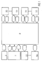
- a RF wireless sensor interface 20 of the present invention as shown in FIG. 1 is structurally configured to interface a variety of sensors in the form of a X number of analog sensors 12 and a Y number of digital sensors 13 to a RF wireless network 11, where X ⁇ 0, Y ⁇ 0 and X +Y ⁇ 1.
- interface 20 may be structurally configured to interface the X number of analog sensors 12, the Y number of digital sensors 13 and RF wireless network 11 to a Z number of interface controlled devices 14, where Z ⁇ 1.
- analog sensor is broadly defined herein as any sensor outputting sensor detection information in analog form.
- digital sensor is broadly defined herein as any sensor outputting sensor detection information in digital form.
- sensor detection information is broadly defined herein as any type of data related to a detection of a physical stimuli (e.g., movement, light and heat) by a sensor.
- RF wireless network is broadly defined herein as any network implementing a RF based communication network protocol.
- interface controlled device is broadly defined herein as any device operable to be switched among a plurality of operational states (e.g., one or more activation states and a deactivation state) as controlled by RF wireless sensor interface 20 based on sensor detection information and/or an interface control information.
- operational states e.g., one or more activation states and a deactivation state
- interface control information is broadly defined herein as any type of data for controlling an operational state of an interface controlled device.
- RF wireless sensor interface 20 converts a primary power P PRM from a primary power source 10 of any type (AC or DC) into a DC power P DC that is supplied to each analog sensor 12 operably coupled via a hardwiring to interface 20 and each digital sensor 13 operably coupled via a hardwiring to interface 20.
- each analog sensor 12 provides its sensor detection information in analog form SDI A to interface 20 and each digital sensor 13 provides its sensor detection information in digital form SDI D to interface 20.
- An example of an analog sensor 12 is a daylight analog sensor structurally configured to output sensor detection information in the form of a daylight indicator ranging between 0 volts (i.e., a sensing of a highest detectable light level) to 10 volts (i.e., a sensing of a lowest detectable light level).
- An example of a digital sensor 13 is an occupancy digital sensor (e.g., ultrasound, infrared and/or acoustic) structurally configured to output its sensor detection information in the form of an occupancy indicator equaling either a logic high level "1" for occupied and a logic low level "0" for vacancy.
- RF wireless sensor interface 20 Upon receiving sensor detection information from one of the sensors, RF wireless sensor interface 20 processes the sensor detection information in accordance with a RF transmission mode or a relay mode. In the RF transmission mode, RF wireless sensor interface 20 processes the sensor detection information in accordance with the RF communication network protocol of RF wireless network 11 to thereby execute a sensor detection information RF transmission SDI RF of the sensor detection information to RF wireless network 11 whereby network 11 utilizes the sensor detection information to control an operation of RF wireless network 11.
- RF wireless sensor interface 20 further processes the sensor detection information in accordance with a network application to thereby execute a sensor control signal RF transmission SCS RF of to RF wireless network 11 whereby RF wireless network 11 is responsive to the sensor control signal to control an operational state of one or more network devices of RF wireless network 11 based on the sensor detection information.
- RF wireless sensor interface 20 further processes the sensor detection information in accordance with a relay application to thereby execute an interface control signal relay ICS RL to one or more interface controlled devices 14 whereby the interface controlled device(s) 14 are responsive to the interface control signal to be switched between operational states based on the sensor detection information.
- RF wireless interface 20 Upon receiving a device control information RF transmission DCI RF from RF wireless network 11, RF wireless interface 20 process the device control information in accordance with a relay application to thereby execute an interface control signal relay ICS RL to one or more interface controlled devices 14 whereby the interface controlled device(s) 14 are responsive to the interface control signal to be switched between operational states based on the device control information received from RF wireless network 11 by RF wireless sensor interface 20.
- RF wireless interface 20 process the sensor detection information and the device control information in accordance with a relay application to thereby execute an interface control signal relay ICS RL to one or more interface controlled devices 14 whereby the interface controlled device(s) 14 are responsive to the interface control signal to be switched between operational states based on the sensor detection information and the device control information.
- FIG. 2 illustrates an exemplary embodiment 21 of interface 20 ( FIG. 1 ) for interfacing one analog sensor 12 ( FIG. 1 ) in the form of a light sensor and one digital sensor 13 ( FIG. 1 ) in the form of an occupancy sensor to a RF wireless network 11 ( FIG. 1 ) in the form of a RF wireless lighting control network and one interface controlled device 14 ( FIG. 1 ) in the form of a lamp of a painting.
- a power converter 30 has three (3) power lead lines 31 (e.g., a line, a neutral and a ground) for receiving an AC power (e.g., a mains AC power) from a AC power source to thereby convert the AC power to a DC power.
- AC power e.g., a mains AC power
- Power converter 30 further has a pair of output power lead lines 32 (e.g. +24 volts and 24 volt return) for providing the DC power to the occupancy sensor, which in response thereto provides sensor detection information in digital form to a microcontroller 60 via a sensor isolation coupler 80 having a sensor control input line 81 coupled to the occupancy sensor and a sensor control output line 82 coupled to microcontroller 60.
- a pair of output power lead lines 32 e.g. +24 volts and 24 volt return
- Power converter 30 further has a pair of output power lead lines 33 for providing the DC power to the light sensor via a sensor isolation coupler 70 having a pair of sensor control lines 71 (e.g., positive control and negative control) coupled to the light sensor, which in response thereto provides sensor detection information in analog form to an analog-to-digital converter (“ADC") 63 of microcontroller 60 via a pair of sensor output lines 72 coupled to ADC 63.
- ADC analog-to-digital converter
- Power converter 30 also powers the other components of RF wireless sensor interface 21 as would be appreciated by those having ordinary skill in the art.
- Microcontroller 60 employs an application manager 62 that is structurally configured to process the sensor detection information from the light sensor in accordance with a network application and a relay application as needed, and to process the device control information received from RF wireless network 11.
- Microcontroller 60 further employs a network stack 61 that is structurally configured for processing any portion of the sensor detection information and any generated sensor control signal to be transmitted to network 11 in accordance with the RF communication network protocol associated with RF wireless network 11, and to process any portion of device control information received from RF wireless network 11 in accordance with the RF communication network protocol associated with RF wireless network 11
- RF transmitter/transceiver 50 executes a sensor detection information RF transmission SDI RF ( FIG. 1 ) via an antenna 40 of sensor detection information to RF wireless network 11 as controlled by microcontroller 60 in response to receiving the sensor detection information from the occupancy sensor.
- RF transmitter/transceiver 50 further executes a sensor control signal RF transmission SCS RF ( FIG. 1 ) via antenna 40 of a sensor control signal to wireless network 11 as controlled by microcontroller 60 in response to receiving the sensor detection information from the light sensor.
- SCS RF sensor control signal
- RF transmitter/transceiver 50 further executes a device control signal RF reception DCI RF ( FIG. 1 ) via antenna 40 of device control information from RF wireless network 11.
- Microcontroller 60 can execute an interface control signal relay ICS RL ( FIG. 1 ) via a pair of relay lines 64 to the interface controlled device 14 in response to receiving the sensor detection information from one of the sensors and/or the device control information from RF wireless network 11.
- ICS RL FIG. 1
- Power converter 30, RF transmitter/transceiver 50, microcontroller 60, coupler 70 and coupler 80 are located within a modular housing 90 to facilitate the operably coupling of the occupancy sensor and the light sensor to RF wireless sensor interface 21.
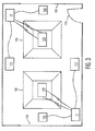
- FIG. 3 illustrates an office space employing a lighting control on each side of the room with each lighting control employing a daylight analog sensor 100 and a occupancy digital sensor 110 interfaced via an RF wireless sensor interface 21 to RF wireless network consisting of a ballast 140 controlling a four (4) lamp device 150.
- each daylight analog sensor 100 is powered by its associated RF wireless sensor interface 21 as previously taught herein to thereby sense a quantity of daylight propagating through an associated window 120 and to provide sensor detection information in the form of a daylight indicator to its associated RF wireless sensor interface 21.
- the RF wireless sensor interface 21 executes a sensor detection information RF transmission SDI RF of the daylight indicator via antenna 40 ( FIG. 2 ) to its associated ballast 140 whereby ballast 140 can control a dimming level of lamp device 150 based on the daylight indicator.
- each occupancy digital sensor 110 is powered by its associated RF wireless sensor interface 21 as previously taught herein to thereby sense an occupancy level of the office relative to people entering and existing an office door 130 and to provide sensor detection information in the form of an occupancy indicator to its associated RF wireless sensor interface 21.
- the RF wireless sensor interface 21 generates a sensor control signal as a function of the network application and executes a sensor control signal RF transmission SCS RF of the sensor control signal via antenna 40 to its associated ballast 140 whereby ballast 140 and lamp device 150 are activated or deactivated based on the sensor control signal.
- the sensor control signal will activate ballast 140 and lamp device 150 if the occupancy indicator represents an occupied office. Otherwise, the sensor control signal will deactivate ballast 140 and lamp device 150 if the occupancy indicator represents a vacant office.
- one of the RF wireless sensor interfaces 21 can also be wired via relay lines 64 ( FIG. 2 ) to an interface controlled device like a stand-alone lamp whereby the lamp is turned on if the daylight indicator represents a nighttime detection and the occupancy indicator represents an occupied office and whereby the lamp is turned off if the daylight indicator represents a daytime detection and/or the occupancy indicator represents a vacant office.
Claims (20)
- Interface de capteur sans fil HF (20) pour interfacer une diversité de capteurs (12, 13) à un réseau sans fil HF (11), l'interface de capteur sans fil HF (20) comprenant :un convertisseur de puissance (30) qui est destiné à convertir une énergie primaire PPRM en un courant continu Pcc et à fournir le courant continu à au moins un de la diversité de capteurs (12, 13) ;un microcontrôleur (60) qui est destiné à recevoir de l'information de détection de capteur SDI en provenance de l'au moins un de la diversité de capteurs (12, 13) en réponse à l'au moins un de la diversité de capteurs (12, 13) recevant le courant continu Pcc en provenance du convertisseur de puissance (30) ;un émetteur-récepteur HF (50) qui est destiné à exécuter au moins une d'une transmission HF de l'information de détection de capteur SDIHF et d'une transmission HF du signal de commande de capteur SCSHF au réseau sans fil HF (11) en réponse au microcontrôleur (60) recevant l'information de détection de capteur SDI ;caractérisée par :un boîtier modulaire dans lequel le convertisseur de puissance (30), le microcontrôleur (60) et l'émetteur-récepteur HF (50) se situent à l'intérieur du boîtier modulaire afin de faciliter un couplage fonctionnel de la diversité de capteurs (12, 13) à l'interface de capteur sans fil HF (20).
- Interface de capteur sans fil HF (20) selon la revendication 1, dans laquelle le microcontrôleur (60) est en outre destiné à exécuter un relais de signal de commande d'interface ICSRL à l'endroit d'un dispositif commandé par l'interface (14) en réponse au microcontrôleur (60) recevant l'information de détection de capteur SDI.
- Interface de capteur sans fil HF (20) selon la revendication 1, dans laquelle le microcontrôleur (60) est en outre destiné à exécuter un relais de signal de commande d'interface ICSRL à l'endroit d'un dispositif commandé par l'interface (14) en réponse à l'émetteur-récepteur HF (50) recevant une transmission HF de l'information de commande de dispositif DCIHF en provenance du réseau sans fil HF (11).
- Interface de capteur sans fil HF (20) selon la revendication 1, dans laquelle le microcontrôleur (60) comprend une pile réseau (61) qui est destinée à faciliter une commande par le microcontrôleur (60) de l'au moins une transmission HF de l'information de détection de capteur SDIHF et d'une transmission HF du signal de commande de capteur SCSHF au réseau sans fil HF (11) par l'émetteur-récepteur HF (50) selon un protocole de communication HF qui est associé au réseau sans fil HF (11).
- Interface de capteur sans fil HF (20) selon la revendication 1, dans laquelle le microcontrôleur (60) comprend un gestionnaire d'applications (62) qui est destiné à générer au moins un d'un signal de commande de capteur en fonction d'une application de réseau du réseau sans fil HF (11) et d'un signal de commande d'interface en fonction d'une application de relais d'un dispositif commandé par l'interface (11).
- Interface de capteur sans fil HF (20) selon la re vendication 1, dans laquelle l'énergie primaire PPRM est un courant alternatif secteur.
- Interface de capteur sans fil HF (20) selon la revendication 1, dans laquelle le réseau sans fil HF (11) est un réseau sans fil de commande d'éclairage.
- Interface de capteur sans fil HF (20) selon la revendication 1, dans laquelle le réseau sans fil HF (11) est un réseau sans fil d'automatisation de bâtiments.
- Interface de capteur sans fil HF (20) selon la revendication 1, dans laquelle la diversité de capteurs (12, 13) comprend un capteur analogique lumière du jour (100).
- Interface de capteur sans fil HF (20) selon la revendication 1, dans laquelle la diversité de capteurs (12, 13) comprend un capteur numérique d'occupation (110).
- Système de détection sans fil HF comprenant :au moins un d'une diversité de capteurs (12, 13) ; etune interface de capteur sans fil HF (20), telle que définie dans la revendication 1.
- Système de détection sans fil HF selon la revendication 11, dans lequel le microcontrôleur (60) est en outre destiné à exécuter un relais de signal de commande d'interface ICSRL à l'endroit d'un dispositif commandé par l'interface (14) en réponse au microcontrôleur (60) recevant l'information de détection de capteur SDI.
- Système de détection sans fil HF selon la revendication 11, dans lequel le microcontrôleur (60) est en outre destiné à exécuter un relais de signal de commande d'interface ICSRL à l'endroit d'un dispositif commandé par l'interface (14) en réponse à l'émetteur-récepteur HF (50) recevant une transmission HF de l'information de commande de dispositif DCIHF en provenance du réseau sans fil HF (11).
- Système de détection sans fil HF selon la revendication 11, dans lequel le microcontrôleur (60) comprend une pile réseau (61) qui est destinée à faciliter une commande par le microcontrôleur (60) de l'au moins une d'une transmission HF de l'information de détection de capteur SDIHF et d'une transmission HF du signal de commande de capteur SCSHF au réseau sans fil HF (11) par l'émetteur-récepteur HF (50) selon un protocole de communication HF qui est associé au réseau sans fil HF (11).
- Système de détection sans fil HF selon la revendication 11, dans lequel le microcontrôleur (60) comprend un gestionnaire d'applications (62) qui est destiné à générer au moins un d'un signal de commande de capteur en fonction d'une application de réseau du réseau sans fil HF (11) et d'un signal de commande d'interface en fonction d'une application de relais d'un dispositif commandé par l'interface (11).
- Système de détection sans fil HF selon la revendication 11, dans lequel l'énergie primaire PPRM est un courant alternatif secteur.
- Système de détection sans fil HF selon la revendication 11, dans lequel le réseau sans fil HF (11) est un réseau sans fil de commande d'éclairage.
- Système de détection sans fil HF selon la revendication 11, dans lequel le réseau sans fil HF (11) est un réseau sans fil d'automatisation de bâtiments.
- Système de détection sans fil HF selon la revendication 11, dans lequel la diversité de capteurs (12, 13) comprend un capteur analogique lumière du jour (100).
- Système de détection sans fil HF selon la revendication 11, dans lequel la diversité de capteurs (12, 13) comprend un capteur numérique d'occupation (110).
Applications Claiming Priority (2)
| Application Number | Priority Date | Filing Date | Title |
|---|---|---|---|
| US73717405P | 2005-11-16 | 2005-11-16 | |
| PCT/IB2006/054228 WO2007057835A2 (fr) | 2005-11-16 | 2006-11-13 | Interface de capteur sans fil hf universel |
Publications (2)
| Publication Number | Publication Date |
|---|---|
| EP1952370A2 EP1952370A2 (fr) | 2008-08-06 |
| EP1952370B1 true EP1952370B1 (fr) | 2010-09-01 |
Family
ID=37903776
Family Applications (1)
| Application Number | Title | Priority Date | Filing Date |
|---|---|---|---|
| EP06821420A Active EP1952370B1 (fr) | 2005-11-16 | 2006-11-13 | Interface de capteur sans fil hf universel |
Country Status (8)
| Country | Link |
|---|---|
| US (1) | US8514072B2 (fr) |
| EP (1) | EP1952370B1 (fr) |
| JP (1) | JP5363110B2 (fr) |
| CN (1) | CN101310313B (fr) |
| AT (1) | ATE479976T1 (fr) |
| DE (1) | DE602006016638D1 (fr) |
| TW (1) | TWI431558B (fr) |
| WO (1) | WO2007057835A2 (fr) |
Families Citing this family (65)
| Publication number | Priority date | Publication date | Assignee | Title |
|---|---|---|---|---|
| ATE479976T1 (de) * | 2005-11-16 | 2010-09-15 | Koninkl Philips Electronics Nv | Universelle drahtlose hf-sensorschnittstelle |
| US7884727B2 (en) * | 2007-05-24 | 2011-02-08 | Bao Tran | Wireless occupancy and day-light sensing |
| JP5141173B2 (ja) * | 2007-10-05 | 2013-02-13 | 富士通株式会社 | 読取り書込み装置との間で無線通信が可能な情報装置、プログラムおよび方法 |
| US8009042B2 (en) * | 2008-09-03 | 2011-08-30 | Lutron Electronics Co., Inc. | Radio-frequency lighting control system with occupancy sensing |
| US8199010B2 (en) | 2009-02-13 | 2012-06-12 | Lutron Electronics Co., Inc. | Method and apparatus for configuring a wireless sensor |
| CN101504792B (zh) * | 2009-02-23 | 2011-06-15 | 四川赛康电气有限责任公司 | 基于无线传感器网络的配电网用户侧集控集抄系统及优化方法 |
| CN102970784A (zh) * | 2011-09-01 | 2013-03-13 | 奥斯兰姆有限公司 | 照明设备和报警系统 |
| TWI475923B (zh) * | 2012-10-05 | 2015-03-01 | Phihong Technology Co Ltd | 用於控制燈具之供電裝置 |
| KR102063110B1 (ko) * | 2013-10-01 | 2020-01-08 | 세메스 주식회사 | 인터페이스 제어 장치 및 그에 의한 구동 전압 모니터링 방법 |
| US10168393B2 (en) | 2014-09-25 | 2019-01-01 | Lockheed Martin Corporation | Micro-vacancy center device |
| US20160216304A1 (en) | 2015-01-28 | 2016-07-28 | Lockheed Martin Corporation | Rapid high-resolution magnetic field measurements for power line inspection |
| US9824597B2 (en) | 2015-01-28 | 2017-11-21 | Lockheed Martin Corporation | Magnetic navigation methods and systems utilizing power grid and communication network |
| US9557391B2 (en) | 2015-01-23 | 2017-01-31 | Lockheed Martin Corporation | Apparatus and method for high sensitivity magnetometry measurement and signal processing in a magnetic detection system |
| US9910104B2 (en) | 2015-01-23 | 2018-03-06 | Lockheed Martin Corporation | DNV magnetic field detector |
| US9614589B1 (en) | 2015-12-01 | 2017-04-04 | Lockheed Martin Corporation | Communication via a magnio |
| US9910105B2 (en) | 2014-03-20 | 2018-03-06 | Lockheed Martin Corporation | DNV magnetic field detector |
| US10338162B2 (en) | 2016-01-21 | 2019-07-02 | Lockheed Martin Corporation | AC vector magnetic anomaly detection with diamond nitrogen vacancies |
| US9638821B2 (en) | 2014-03-20 | 2017-05-02 | Lockheed Martin Corporation | Mapping and monitoring of hydraulic fractures using vector magnetometers |
| GB2540308B (en) | 2014-04-07 | 2018-05-16 | Lockheed Corp | Energy efficient controlled magnetic field generator circuit |
| US9143968B1 (en) | 2014-07-18 | 2015-09-22 | Cognitive Systems Corp. | Wireless spectrum monitoring and analysis |
| US9883567B2 (en) | 2014-08-11 | 2018-01-30 | RAB Lighting Inc. | Device indication and commissioning for a lighting control system |
| US10039174B2 (en) | 2014-08-11 | 2018-07-31 | RAB Lighting Inc. | Systems and methods for acknowledging broadcast messages in a wireless lighting control network |
| US10085328B2 (en) | 2014-08-11 | 2018-09-25 | RAB Lighting Inc. | Wireless lighting control systems and methods |
| US10531545B2 (en) | 2014-08-11 | 2020-01-07 | RAB Lighting Inc. | Commissioning a configurable user control device for a lighting control system |
| US9143413B1 (en) | 2014-10-22 | 2015-09-22 | Cognitive Systems Corp. | Presenting wireless-spectrum usage information |
| US9535155B2 (en) | 2015-02-04 | 2017-01-03 | Cognitive Systems Corp. | Locating the source of a wireless signal |
| WO2016126436A1 (fr) | 2015-02-04 | 2016-08-11 | Lockheed Martin Corporation | Appareil et procédé pour la récupération de champ magnétique en trois dimensions à partir d'un système de détection magnétique |
| GB2550809A (en) | 2015-02-04 | 2017-11-29 | Lockheed Corp | Apparatus and method for estimating absolute axes' orientations for a magnetic detection system |
| US9860763B2 (en) | 2015-03-25 | 2018-01-02 | Cognitive Systems Corp. | Analyzing wireless network performance |
| US9344907B1 (en) * | 2015-06-04 | 2016-05-17 | Cognitive Systems Corp. | Analyzing wireless signal propagation |
| EP3371614A1 (fr) | 2015-11-04 | 2018-09-12 | Lockheed Martin Corporation | Filtre passe-bande magnétique |
| WO2017087013A1 (fr) | 2015-11-20 | 2017-05-26 | Lockheed Martin Corporation | Appareil et procédé de traitement en boucle fermée pour un système de détection magnétique |
| WO2017087014A1 (fr) | 2015-11-20 | 2017-05-26 | Lockheed Martin Corporation | Appareil et procédé de détection de l'hypersensibilité d'un champ magnétique |
| WO2017123261A1 (fr) | 2016-01-12 | 2017-07-20 | Lockheed Martin Corporation | Détecteur de défauts pour matériaux conducteurs |
| WO2017127090A1 (fr) | 2016-01-21 | 2017-07-27 | Lockheed Martin Corporation | Sensibilité magnétique supérieure par manipulation de fluorescence par contrôle de spectre de phonons |
| WO2017127094A1 (fr) | 2016-01-21 | 2017-07-27 | Lockheed Martin Corporation | Magnétomètre à conduit de lumière |
| WO2017127097A1 (fr) | 2016-01-21 | 2017-07-27 | Lockheed Martin Corporation | Magnétomètre doté d'une diode électroluminescente |
| WO2017127098A1 (fr) | 2016-01-21 | 2017-07-27 | Lockheed Martin Corporation | Hydrophone à ferrofluide à détection de lacune d'azote dans une structure diamant |
| GB2562193B (en) | 2016-01-21 | 2021-12-22 | Lockheed Corp | Diamond nitrogen vacancy sensor with common RF and magnetic fields generator |
| WO2017127096A1 (fr) | 2016-01-21 | 2017-07-27 | Lockheed Martin Corporation | Capteur d'azote-lacune de diamant avec doubles sources rf |
| EP3405603A4 (fr) | 2016-01-21 | 2019-10-16 | Lockheed Martin Corporation | Capteur azote-lacune de diamant avec circuit sur le diamant |
| US10317279B2 (en) | 2016-05-31 | 2019-06-11 | Lockheed Martin Corporation | Optical filtration system for diamond material with nitrogen vacancy centers |
| US10677953B2 (en) | 2016-05-31 | 2020-06-09 | Lockheed Martin Corporation | Magneto-optical detecting apparatus and methods |
| US10281550B2 (en) | 2016-11-14 | 2019-05-07 | Lockheed Martin Corporation | Spin relaxometry based molecular sequencing |
| US10408890B2 (en) | 2017-03-24 | 2019-09-10 | Lockheed Martin Corporation | Pulsed RF methods for optimization of CW measurements |
| US10345395B2 (en) | 2016-12-12 | 2019-07-09 | Lockheed Martin Corporation | Vector magnetometry localization of subsurface liquids |
| US10228429B2 (en) | 2017-03-24 | 2019-03-12 | Lockheed Martin Corporation | Apparatus and method for resonance magneto-optical defect center material pulsed mode referencing |
| US10371765B2 (en) | 2016-07-11 | 2019-08-06 | Lockheed Martin Corporation | Geolocation of magnetic sources using vector magnetometer sensors |
| US10274550B2 (en) | 2017-03-24 | 2019-04-30 | Lockheed Martin Corporation | High speed sequential cancellation for pulsed mode |
| US10145910B2 (en) | 2017-03-24 | 2018-12-04 | Lockheed Martin Corporation | Photodetector circuit saturation mitigation for magneto-optical high intensity pulses |
| US10330744B2 (en) | 2017-03-24 | 2019-06-25 | Lockheed Martin Corporation | Magnetometer with a waveguide |
| US10345396B2 (en) | 2016-05-31 | 2019-07-09 | Lockheed Martin Corporation | Selected volume continuous illumination magnetometer |
| US10359479B2 (en) | 2017-02-20 | 2019-07-23 | Lockheed Martin Corporation | Efficient thermal drift compensation in DNV vector magnetometry |
| US20170343621A1 (en) | 2016-05-31 | 2017-11-30 | Lockheed Martin Corporation | Magneto-optical defect center magnetometer |
| US10571530B2 (en) | 2016-05-31 | 2020-02-25 | Lockheed Martin Corporation | Buoy array of magnetometers |
| US10527746B2 (en) | 2016-05-31 | 2020-01-07 | Lockheed Martin Corporation | Array of UAVS with magnetometers |
| US10338163B2 (en) | 2016-07-11 | 2019-07-02 | Lockheed Martin Corporation | Multi-frequency excitation schemes for high sensitivity magnetometry measurement with drift error compensation |
| US10338164B2 (en) | 2017-03-24 | 2019-07-02 | Lockheed Martin Corporation | Vacancy center material with highly efficient RF excitation |
| US10371760B2 (en) | 2017-03-24 | 2019-08-06 | Lockheed Martin Corporation | Standing-wave radio frequency exciter |
| WO2018174915A1 (fr) * | 2017-03-24 | 2018-09-27 | Lockheed Martin Corporation | Capteur de centre des anomalies magnéto-optiques à réseau d'antennes rf vivaldi |
| WO2018174910A1 (fr) * | 2017-03-24 | 2018-09-27 | Lockheed Martin Corporation | Excitateur radiofréquence à ondes stationnaires |
| US10459041B2 (en) | 2017-03-24 | 2019-10-29 | Lockheed Martin Corporation | Magnetic detection system with highly integrated diamond nitrogen vacancy sensor |
| WO2018174911A1 (fr) * | 2017-03-24 | 2018-09-27 | Lockheed Martin Corporation | Génération de mandataire de champ magnétique par juxtaposition de fréquences rf |
| US10379174B2 (en) | 2017-03-24 | 2019-08-13 | Lockheed Martin Corporation | Bias magnet array for magnetometer |
| CN111431562B (zh) * | 2020-03-05 | 2022-01-11 | 许昌北邮万联网络技术有限公司 | 一种消防信息传输系统、方法及装置 |
Family Cites Families (18)
| Publication number | Priority date | Publication date | Assignee | Title |
|---|---|---|---|---|
| US5426416A (en) * | 1992-10-19 | 1995-06-20 | Westinghouse Electric Corporation | Automotive current sensor |
| JP3465914B2 (ja) * | 1992-12-01 | 2003-11-10 | 松下電器産業株式会社 | シーン制御処理装置 |
| US5532680A (en) * | 1995-03-27 | 1996-07-02 | Ousborne; Jeffrey | Automatic message playback system |
| JPH10136110A (ja) * | 1996-10-28 | 1998-05-22 | Toshiba Corp | 家庭内情報システム |
| JPH11164420A (ja) * | 1997-09-26 | 1999-06-18 | Fuji Electric Co Ltd | 変電所の監視システム |
| KR100682523B1 (ko) * | 1999-01-25 | 2007-02-15 | 젠텍스 코포레이션 | 반도체 광 센서들을 가진 차량 기기 제어장치 |
| DE10103302A1 (de) * | 2001-01-25 | 2002-08-01 | Bsh Bosch Siemens Hausgeraete | Elektrisches Haushaltsgerät mit Kommunikationsschnittstelle |
| JP2003016831A (ja) * | 2001-06-29 | 2003-01-17 | Hittsu Kenkyusho:Kk | 通信機能モジュール |
| DE60330750D1 (de) * | 2002-01-28 | 2010-02-11 | Siemens Building Tech Ag | Gebaudeautomatisierungssystem und dafür entsprechendes rauchabzugssystem mit verminderten verdrahtungsanforderungen |
| AU2003259506A1 (en) | 2002-09-04 | 2004-03-29 | Koninklijke Philips Electronics N.V. | Master-slave oriented two-way rf wireless lighting control system |
| US20040217847A1 (en) * | 2003-01-24 | 2004-11-04 | Fries Robert G. | Wireless sensing system |
| US7135976B2 (en) * | 2003-03-31 | 2006-11-14 | Rftrax, Inc. | Wireless monitoring device |
| GB0318380D0 (en) | 2003-08-06 | 2003-09-10 | Intelligent Electrics Ltd | Remote control |
| US7664573B2 (en) * | 2003-09-26 | 2010-02-16 | Siemens Industry, Inc. | Integrated building environment data system |
| US7148803B2 (en) * | 2003-10-24 | 2006-12-12 | Symbol Technologies, Inc. | Radio frequency identification (RFID) based sensor networks |
| US20060006817A1 (en) * | 2004-05-13 | 2006-01-12 | Chason Marc K | AC powered self organizing wireless node |
| US7386404B2 (en) * | 2005-05-27 | 2008-06-10 | Savi Technology, Inc. | Method and apparatus for monitoring battery discharge state |
| ATE479976T1 (de) * | 2005-11-16 | 2010-09-15 | Koninkl Philips Electronics Nv | Universelle drahtlose hf-sensorschnittstelle |
-
2006
- 2006-11-13 AT AT06821420T patent/ATE479976T1/de not_active IP Right Cessation
- 2006-11-13 WO PCT/IB2006/054228 patent/WO2007057835A2/fr active Application Filing
- 2006-11-13 EP EP06821420A patent/EP1952370B1/fr active Active
- 2006-11-13 CN CN2006800428361A patent/CN101310313B/zh active Active
- 2006-11-13 DE DE602006016638T patent/DE602006016638D1/de active Active
- 2006-11-13 US US12/093,335 patent/US8514072B2/en active Active
- 2006-11-13 JP JP2008540757A patent/JP5363110B2/ja active Active
- 2006-11-13 TW TW095141848A patent/TWI431558B/zh active
Also Published As
| Publication number | Publication date |
|---|---|
| JP2009517896A (ja) | 2009-04-30 |
| TW200741601A (en) | 2007-11-01 |
| WO2007057835A3 (fr) | 2007-06-07 |
| CN101310313A (zh) | 2008-11-19 |
| US8514072B2 (en) | 2013-08-20 |
| EP1952370A2 (fr) | 2008-08-06 |
| TWI431558B (zh) | 2014-03-21 |
| CN101310313B (zh) | 2010-09-01 |
| DE602006016638D1 (de) | 2010-10-14 |
| JP5363110B2 (ja) | 2013-12-11 |
| US20080266050A1 (en) | 2008-10-30 |
| ATE479976T1 (de) | 2010-09-15 |
| WO2007057835A2 (fr) | 2007-05-24 |
Similar Documents
| Publication | Publication Date | Title |
|---|---|---|
| EP1952370B1 (fr) | Interface de capteur sans fil hf universel | |
| US20090256708A1 (en) | System and method of rfid wireless control | |
| CA2523313A1 (fr) | Emetteur d'interrupteur d'eclairage va-et-vient a commande sans fil en courant alternatif | |
| US8436552B2 (en) | Power source control device of illuminator and lighting system | |
| US20110148309A1 (en) | Occupancy sensor with embedded signaling capability | |
| WO2015155991A1 (fr) | Système de commande de coopération de dispositifs, appareil de commande de dispositif, dispositif, procédé pour commander les dispositifs du système de commande de coopération de dispositifs, et leur programme | |
| KR100624792B1 (ko) | 무선 네트워크 시스템 | |
| JP2007174095A (ja) | ワイヤレス配線器具および負荷制御システム | |
| EP3567990A1 (fr) | Dispositif de commande de lampe sans fil présentant une alimentation électrique indépendante et système de lampe associé | |
| WO2011043599A2 (fr) | Dispositif interrupteur de lampe sans fil et tactile combiné | |
| US9872366B2 (en) | Method for controlling an operating device for lighting means | |
| KR20060134238A (ko) | 다수의 조명을 제어하는 시스템 | |
| JP2008228427A (ja) | スイッチングシステム | |
| US9287708B2 (en) | Actuator and energy management system comprising such actuators | |
| KR101677131B1 (ko) | 블루투스를 이용한 조명 제어 시스템 | |
| KR20030050407A (ko) | 전력선 통신 방법을 이용한 원격 제어 스위치 장치 | |
| JP7330547B2 (ja) | リモコン通信を用いた節電制御システム | |
| US20110148193A1 (en) | Networked occupancy sensor and power pack | |
| CN101272649B (zh) | 热射线无线发送机 | |
| KR200446054Y1 (ko) | 무선통신을 이용한 조명 제어시스템 | |
| JPH11273875A (ja) | 照明制御システム | |
| KR20050055378A (ko) | 알에프 신호를 이용한 벽매립형 전등스위치의 무선제어장치 | |
| AU2008243098B2 (en) | Switching system | |
| KR200269528Y1 (ko) | 전기기구의 원격 제어장치 | |
| KR101946881B1 (ko) | 조명 시스템 정보 초기화 장치 및 방법 |
Legal Events
| Date | Code | Title | Description |
|---|---|---|---|
| PUAI | Public reference made under article 153(3) epc to a published international application that has entered the european phase |
Free format text: ORIGINAL CODE: 0009012 |
|
| 17P | Request for examination filed |
Effective date: 20080616 |
|
| AK | Designated contracting states |
Kind code of ref document: A2 Designated state(s): AT BE BG CH CY CZ DE DK EE ES FI FR GB GR HU IE IS IT LI LT LU LV MC NL PL PT RO SE SI SK TR |
|
| GRAP | Despatch of communication of intention to grant a patent |
Free format text: ORIGINAL CODE: EPIDOSNIGR1 |
|
| GRAS | Grant fee paid |
Free format text: ORIGINAL CODE: EPIDOSNIGR3 |
|
| GRAA | (expected) grant |
Free format text: ORIGINAL CODE: 0009210 |
|
| AK | Designated contracting states |
Kind code of ref document: B1 Designated state(s): AT BE BG CH CY CZ DE DK EE ES FI FR GB GR HU IE IS IT LI LT LU LV MC NL PL PT RO SE SI SK TR |
|
| REG | Reference to a national code |
Ref country code: GB Ref legal event code: FG4D |
|
| REG | Reference to a national code |
Ref country code: CH Ref legal event code: EP |
|
| REG | Reference to a national code |
Ref country code: IE Ref legal event code: FG4D |
|
| REF | Corresponds to: |
Ref document number: 602006016638 Country of ref document: DE Date of ref document: 20101014 Kind code of ref document: P |
|
| REG | Reference to a national code |
Ref country code: NL Ref legal event code: VDEP Effective date: 20100901 |
|
| PG25 | Lapsed in a contracting state [announced via postgrant information from national office to epo] |
Ref country code: AT Free format text: LAPSE BECAUSE OF FAILURE TO SUBMIT A TRANSLATION OF THE DESCRIPTION OR TO PAY THE FEE WITHIN THE PRESCRIBED TIME-LIMIT Effective date: 20100901 Ref country code: FI Free format text: LAPSE BECAUSE OF FAILURE TO SUBMIT A TRANSLATION OF THE DESCRIPTION OR TO PAY THE FEE WITHIN THE PRESCRIBED TIME-LIMIT Effective date: 20100901 Ref country code: LT Free format text: LAPSE BECAUSE OF FAILURE TO SUBMIT A TRANSLATION OF THE DESCRIPTION OR TO PAY THE FEE WITHIN THE PRESCRIBED TIME-LIMIT Effective date: 20100901 |
|
| LTIE | Lt: invalidation of european patent or patent extension |
Effective date: 20100901 |
|
| PG25 | Lapsed in a contracting state [announced via postgrant information from national office to epo] |
Ref country code: PL Free format text: LAPSE BECAUSE OF FAILURE TO SUBMIT A TRANSLATION OF THE DESCRIPTION OR TO PAY THE FEE WITHIN THE PRESCRIBED TIME-LIMIT Effective date: 20100901 Ref country code: CY Free format text: LAPSE BECAUSE OF FAILURE TO SUBMIT A TRANSLATION OF THE DESCRIPTION OR TO PAY THE FEE WITHIN THE PRESCRIBED TIME-LIMIT Effective date: 20100901 Ref country code: SI Free format text: LAPSE BECAUSE OF FAILURE TO SUBMIT A TRANSLATION OF THE DESCRIPTION OR TO PAY THE FEE WITHIN THE PRESCRIBED TIME-LIMIT Effective date: 20100901 |
|
| PG25 | Lapsed in a contracting state [announced via postgrant information from national office to epo] |
Ref country code: SE Free format text: LAPSE BECAUSE OF FAILURE TO SUBMIT A TRANSLATION OF THE DESCRIPTION OR TO PAY THE FEE WITHIN THE PRESCRIBED TIME-LIMIT Effective date: 20100901 Ref country code: GR Free format text: LAPSE BECAUSE OF FAILURE TO SUBMIT A TRANSLATION OF THE DESCRIPTION OR TO PAY THE FEE WITHIN THE PRESCRIBED TIME-LIMIT Effective date: 20101202 Ref country code: NL Free format text: LAPSE BECAUSE OF FAILURE TO SUBMIT A TRANSLATION OF THE DESCRIPTION OR TO PAY THE FEE WITHIN THE PRESCRIBED TIME-LIMIT Effective date: 20100901 Ref country code: LV Free format text: LAPSE BECAUSE OF FAILURE TO SUBMIT A TRANSLATION OF THE DESCRIPTION OR TO PAY THE FEE WITHIN THE PRESCRIBED TIME-LIMIT Effective date: 20100901 |
|
| PG25 | Lapsed in a contracting state [announced via postgrant information from national office to epo] |
Ref country code: PT Free format text: LAPSE BECAUSE OF FAILURE TO SUBMIT A TRANSLATION OF THE DESCRIPTION OR TO PAY THE FEE WITHIN THE PRESCRIBED TIME-LIMIT Effective date: 20110103 Ref country code: RO Free format text: LAPSE BECAUSE OF FAILURE TO SUBMIT A TRANSLATION OF THE DESCRIPTION OR TO PAY THE FEE WITHIN THE PRESCRIBED TIME-LIMIT Effective date: 20100901 Ref country code: IS Free format text: LAPSE BECAUSE OF FAILURE TO SUBMIT A TRANSLATION OF THE DESCRIPTION OR TO PAY THE FEE WITHIN THE PRESCRIBED TIME-LIMIT Effective date: 20110101 Ref country code: EE Free format text: LAPSE BECAUSE OF FAILURE TO SUBMIT A TRANSLATION OF THE DESCRIPTION OR TO PAY THE FEE WITHIN THE PRESCRIBED TIME-LIMIT Effective date: 20100901 Ref country code: IT Free format text: LAPSE BECAUSE OF FAILURE TO SUBMIT A TRANSLATION OF THE DESCRIPTION OR TO PAY THE FEE WITHIN THE PRESCRIBED TIME-LIMIT Effective date: 20100901 Ref country code: SK Free format text: LAPSE BECAUSE OF FAILURE TO SUBMIT A TRANSLATION OF THE DESCRIPTION OR TO PAY THE FEE WITHIN THE PRESCRIBED TIME-LIMIT Effective date: 20100901 Ref country code: CZ Free format text: LAPSE BECAUSE OF FAILURE TO SUBMIT A TRANSLATION OF THE DESCRIPTION OR TO PAY THE FEE WITHIN THE PRESCRIBED TIME-LIMIT Effective date: 20100901 |
|
| PG25 | Lapsed in a contracting state [announced via postgrant information from national office to epo] |
Ref country code: MC Free format text: LAPSE BECAUSE OF NON-PAYMENT OF DUE FEES Effective date: 20101130 Ref country code: BE Free format text: LAPSE BECAUSE OF FAILURE TO SUBMIT A TRANSLATION OF THE DESCRIPTION OR TO PAY THE FEE WITHIN THE PRESCRIBED TIME-LIMIT Effective date: 20100901 Ref country code: ES Free format text: LAPSE BECAUSE OF FAILURE TO SUBMIT A TRANSLATION OF THE DESCRIPTION OR TO PAY THE FEE WITHIN THE PRESCRIBED TIME-LIMIT Effective date: 20101212 |
|
| REG | Reference to a national code |
Ref country code: CH Ref legal event code: PL |
|
| PLBE | No opposition filed within time limit |
Free format text: ORIGINAL CODE: 0009261 |
|
| STAA | Information on the status of an ep patent application or granted ep patent |
Free format text: STATUS: NO OPPOSITION FILED WITHIN TIME LIMIT |
|
| PG25 | Lapsed in a contracting state [announced via postgrant information from national office to epo] |
Ref country code: LI Free format text: LAPSE BECAUSE OF NON-PAYMENT OF DUE FEES Effective date: 20101130 Ref country code: CH Free format text: LAPSE BECAUSE OF NON-PAYMENT OF DUE FEES Effective date: 20101130 |
|
| 26N | No opposition filed |
Effective date: 20110606 |
|
| PG25 | Lapsed in a contracting state [announced via postgrant information from national office to epo] |
Ref country code: DK Free format text: LAPSE BECAUSE OF FAILURE TO SUBMIT A TRANSLATION OF THE DESCRIPTION OR TO PAY THE FEE WITHIN THE PRESCRIBED TIME-LIMIT Effective date: 20100901 |
|
| REG | Reference to a national code |
Ref country code: DE Ref legal event code: R097 Ref document number: 602006016638 Country of ref document: DE Effective date: 20110606 |
|
| PG25 | Lapsed in a contracting state [announced via postgrant information from national office to epo] |
Ref country code: IE Free format text: LAPSE BECAUSE OF NON-PAYMENT OF DUE FEES Effective date: 20101113 |
|
| PG25 | Lapsed in a contracting state [announced via postgrant information from national office to epo] |
Ref country code: BG Free format text: LAPSE BECAUSE OF FAILURE TO SUBMIT A TRANSLATION OF THE DESCRIPTION OR TO PAY THE FEE WITHIN THE PRESCRIBED TIME-LIMIT Effective date: 20100901 Ref country code: LU Free format text: LAPSE BECAUSE OF NON-PAYMENT OF DUE FEES Effective date: 20101113 Ref country code: HU Free format text: LAPSE BECAUSE OF FAILURE TO SUBMIT A TRANSLATION OF THE DESCRIPTION OR TO PAY THE FEE WITHIN THE PRESCRIBED TIME-LIMIT Effective date: 20110302 |
|
| PG25 | Lapsed in a contracting state [announced via postgrant information from national office to epo] |
Ref country code: TR Free format text: LAPSE BECAUSE OF FAILURE TO SUBMIT A TRANSLATION OF THE DESCRIPTION OR TO PAY THE FEE WITHIN THE PRESCRIBED TIME-LIMIT Effective date: 20100901 |
|
| PG25 | Lapsed in a contracting state [announced via postgrant information from national office to epo] |
Ref country code: BG Free format text: LAPSE BECAUSE OF FAILURE TO SUBMIT A TRANSLATION OF THE DESCRIPTION OR TO PAY THE FEE WITHIN THE PRESCRIBED TIME-LIMIT Effective date: 20101201 |
|
| REG | Reference to a national code |
Ref country code: DE Ref legal event code: R082 Ref document number: 602006016638 Country of ref document: DE Representative=s name: MEISSNER, BOLTE & PARTNER GBR, DE |
|
| REG | Reference to a national code |
Ref country code: DE Ref legal event code: R082 Ref document number: 602006016638 Country of ref document: DE Representative=s name: MEISSNER BOLTE PATENTANWAELTE RECHTSANWAELTE P, DE Effective date: 20140328 Ref country code: DE Ref legal event code: R081 Ref document number: 602006016638 Country of ref document: DE Owner name: PHILIPS LIGHTING HOLDING B.V., NL Free format text: FORMER OWNER: KONINKLIJKE PHILIPS ELECTRONICS N.V., EINDHOVEN, NL Effective date: 20140328 Ref country code: DE Ref legal event code: R081 Ref document number: 602006016638 Country of ref document: DE Owner name: KONINKLIJKE PHILIPS N.V., NL Free format text: FORMER OWNER: KONINKLIJKE PHILIPS ELECTRONICS N.V., EINDHOVEN, NL Effective date: 20140328 Ref country code: DE Ref legal event code: R082 Ref document number: 602006016638 Country of ref document: DE Representative=s name: MEISSNER, BOLTE & PARTNER GBR, DE Effective date: 20140328 |
|
| REG | Reference to a national code |
Ref country code: FR Ref legal event code: CA Effective date: 20141126 Ref country code: FR Ref legal event code: CD Owner name: KONINKLIJKE PHILIPS ELECTRONICS N.V., NL Effective date: 20141126 |
|
| REG | Reference to a national code |
Ref country code: FR Ref legal event code: PLFP Year of fee payment: 10 |
|
| REG | Reference to a national code |
Ref country code: GB Ref legal event code: 732E Free format text: REGISTERED BETWEEN 20161006 AND 20161012 |
|
| REG | Reference to a national code |
Ref country code: FR Ref legal event code: PLFP Year of fee payment: 11 |
|
| REG | Reference to a national code |
Ref country code: DE Ref legal event code: R081 Ref document number: 602006016638 Country of ref document: DE Owner name: SIGNIFY HOLDING B.V., NL Free format text: FORMER OWNER: KONINKLIJKE PHILIPS N.V., EINDHOVEN, NL Ref country code: DE Ref legal event code: R082 Ref document number: 602006016638 Country of ref document: DE Representative=s name: MEISSNER BOLTE PATENTANWAELTE RECHTSANWAELTE P, DE Ref country code: DE Ref legal event code: R081 Ref document number: 602006016638 Country of ref document: DE Owner name: PHILIPS LIGHTING HOLDING B.V., NL Free format text: FORMER OWNER: KONINKLIJKE PHILIPS N.V., EINDHOVEN, NL |
|
| REG | Reference to a national code |
Ref country code: FR Ref legal event code: PLFP Year of fee payment: 12 |
|
| REG | Reference to a national code |
Ref country code: DE Ref legal event code: R082 Ref document number: 602006016638 Country of ref document: DE Representative=s name: MEISSNER BOLTE PATENTANWAELTE RECHTSANWAELTE P, DE Ref country code: DE Ref legal event code: R081 Ref document number: 602006016638 Country of ref document: DE Owner name: SIGNIFY HOLDING B.V., NL Free format text: FORMER OWNER: PHILIPS LIGHTING HOLDING B.V., EINDHOVEN, NL |
|
| PGFP | Annual fee paid to national office [announced via postgrant information from national office to epo] |
Ref country code: DE Payment date: 20230127 Year of fee payment: 17 |
|
| P01 | Opt-out of the competence of the unified patent court (upc) registered |
Effective date: 20230421 |
|
| PGFP | Annual fee paid to national office [announced via postgrant information from national office to epo] |
Ref country code: GB Payment date: 20231121 Year of fee payment: 18 |
|
| PGFP | Annual fee paid to national office [announced via postgrant information from national office to epo] |
Ref country code: FR Payment date: 20231123 Year of fee payment: 18 |