EP1950492A1 - Lamp for vehicles, in particular motor vehicles - Google Patents
Lamp for vehicles, in particular motor vehicles Download PDFInfo
- Publication number
- EP1950492A1 EP1950492A1 EP08000996A EP08000996A EP1950492A1 EP 1950492 A1 EP1950492 A1 EP 1950492A1 EP 08000996 A EP08000996 A EP 08000996A EP 08000996 A EP08000996 A EP 08000996A EP 1950492 A1 EP1950492 A1 EP 1950492A1
- Authority
- EP
- European Patent Office
- Prior art keywords
- light
- lens
- luminaire according
- windows
- luminaire
- Prior art date
- Legal status (The legal status is an assumption and is not a legal conclusion. Google has not performed a legal analysis and makes no representation as to the accuracy of the status listed.)
- Granted
Links
Images


Classifications
-
- B—PERFORMING OPERATIONS; TRANSPORTING
- B60—VEHICLES IN GENERAL
- B60Q—ARRANGEMENT OF SIGNALLING OR LIGHTING DEVICES, THE MOUNTING OR SUPPORTING THEREOF OR CIRCUITS THEREFOR, FOR VEHICLES IN GENERAL
- B60Q1/00—Arrangement of optical signalling or lighting devices, the mounting or supporting thereof or circuits therefor
- B60Q1/26—Arrangement of optical signalling or lighting devices, the mounting or supporting thereof or circuits therefor the devices being primarily intended to indicate the vehicle, or parts thereof, or to give signals, to other traffic
- B60Q1/2607—Arrangement of optical signalling or lighting devices, the mounting or supporting thereof or circuits therefor the devices being primarily intended to indicate the vehicle, or parts thereof, or to give signals, to other traffic comprising at least two indicating lamps
-
- B—PERFORMING OPERATIONS; TRANSPORTING
- B60—VEHICLES IN GENERAL
- B60Q—ARRANGEMENT OF SIGNALLING OR LIGHTING DEVICES, THE MOUNTING OR SUPPORTING THEREOF OR CIRCUITS THEREFOR, FOR VEHICLES IN GENERAL
- B60Q1/00—Arrangement of optical signalling or lighting devices, the mounting or supporting thereof or circuits therefor
- B60Q1/26—Arrangement of optical signalling or lighting devices, the mounting or supporting thereof or circuits therefor the devices being primarily intended to indicate the vehicle, or parts thereof, or to give signals, to other traffic
- B60Q1/30—Arrangement of optical signalling or lighting devices, the mounting or supporting thereof or circuits therefor the devices being primarily intended to indicate the vehicle, or parts thereof, or to give signals, to other traffic for indicating rear of vehicle, e.g. by means of reflecting surfaces
- B60Q1/304—Adaptations of signalling devices having a part on the vehicle body and another on the boot door
-
- F—MECHANICAL ENGINEERING; LIGHTING; HEATING; WEAPONS; BLASTING
- F21—LIGHTING
- F21S—NON-PORTABLE LIGHTING DEVICES; SYSTEMS THEREOF; VEHICLE LIGHTING DEVICES SPECIALLY ADAPTED FOR VEHICLE EXTERIORS
- F21S43/00—Signalling devices specially adapted for vehicle exteriors, e.g. brake lamps, direction indicator lights or reversing lights
- F21S43/20—Signalling devices specially adapted for vehicle exteriors, e.g. brake lamps, direction indicator lights or reversing lights characterised by refractors, transparent cover plates, light guides or filters
- F21S43/26—Refractors, transparent cover plates, light guides or filters not provided in groups F21S43/235 - F21S43/255
-
- F—MECHANICAL ENGINEERING; LIGHTING; HEATING; WEAPONS; BLASTING
- F21—LIGHTING
- F21S—NON-PORTABLE LIGHTING DEVICES; SYSTEMS THEREOF; VEHICLE LIGHTING DEVICES SPECIALLY ADAPTED FOR VEHICLE EXTERIORS
- F21S43/00—Signalling devices specially adapted for vehicle exteriors, e.g. brake lamps, direction indicator lights or reversing lights
- F21S43/20—Signalling devices specially adapted for vehicle exteriors, e.g. brake lamps, direction indicator lights or reversing lights characterised by refractors, transparent cover plates, light guides or filters
- F21S43/255—Filters
Definitions
- the invention relates to a luminaire for vehicles, preferably for motor vehicles, according to the preamble of claim 1.
- a luminaire which is designed as a headlight for vehicles.
- the lamp has a housing, a lens and a light source.
- the lens has in the center a first partial surface with optical deflection properties. In the outer edge region between this partial surface and the lens, this is at least partially transparent. By this measure, a sharp contour of the first central part surface is achieved, which also also has optical Blink properties.
- the invention has for its object to design the generic lamp so that their split light windows are perceived in a simple design and cost-effective production in the illuminated state as a closed luminous area.
- the luminaire according to the invention is located in the opaque area between the two light windows of the additional transparent area. It is achieved that, despite the split light window, a coherent light window required by the legislator can be recognized by a viewer if the two light windows have the same light function fulfill.
- the additional translucent area can be small. It is arranged in the intermediate area between the light windows so that a viewer perceives all the light windows as a single light window.
- the non-luminous intermediate areas blur at a certain distance in the eye of the beholder, so that he no longer perceives the light windows and the additional translucent area as a single light window.
- Such light windows in luminaires are of particular interest when design-relevant areas of the luminaire are to act as part of the bodywork. A division into individual light windows is then no longer avoidable. As an alternative, then only the enlargement of the lamp is available in total, since the legal minimum surfaces of the light functions of the lamp must be met. However, such large lights are unacceptable for aesthetic reasons. With the luminaire according to the invention, the legal minimum surfaces of the lighting functions can be fulfilled without the luminaire having to be enlarged overall.
- the lamp according to the invention also has the advantage that it can be produced very inexpensively, since essentially the same tools as standard lamps can be used.
- Fig. 1 shows a lamp 1 with two separate light windows 6, 7 for a common light or signal function.
- the light 1 is a rear light for motor vehicles, which is divided into two parts 2 and 3.
- the parting line 3 of the light parts 2, 3 is located between the body of the motor vehicle and the rear lid flap.
- the light part 2 is attached to the body side in the fender, while the light part 3 is fixed in or on the trunk lid or trunk lid.
- the body-side light part 2 is exemplarily smaller than the flap-side light part 3.
- the proportions may also be reversed, or both light parts 2, 3 may have the same size.
- the luminaire parts 2, 3 can have very different outlines.
- Both light parts 2, 3 each have the upper light window 6 and the lower light window 7, which are each separated by an opaque or partially transmissive region 11 from each other. This is arranged substantially centrally to the luminaire parts 2, 3.
- the area 11 is, for example, a colored or painted in the body color part of a lens 20, which closes the lamp 1 on one side. Behind the area 11, at least one light source 31 (FIG. Fig. 3 to 5 ), which only this area 11 is similar to a position light in a weak, dull light appears or illuminated.
- the light-emitting means 31 is an incandescent lamp in the exemplary embodiment, but it can also be an LED or another light source.
- the bulb sits in a socket 32 to which electrical leads 33 are connected to power the incandescent lamp.
- each luminaire part 2, 3 can be connected to each other within the luminaire 1.
- a single illuminant 31 is sufficient if its light is reflected by a common reflector 30 to the light windows. An outside observer then has the impression that it is two individual lights.
- each a separate lighting area may be provided, which has at least one lamp 31 and at least one reflector 30.
- the two light windows 6, 7 of the light parts 2, 3 can be assigned the same light functions 15 and different light functions 15, 17.
- the upper light window 6 of the flap-side light part 3 may have the same light function 15 to 17 as the upper and lower light windows 6, 7 of the body-side light part 2.
- the lower light window 7 of the flap-side light part 3 may be divided into two or more different light functions, for example ,
- the lower half can be designed, for example, as a rear fog lamp 16 or reversing light 19.
- the upper half of this lower light window 7 can form, for example, a reflection reflector 18.
- a wide variety of combinations and connections are possible with these light functions.
- the light windows 6, 7 of the body-side light part 2 have a multiple light function, for example, with an existing tail light 15th a direction indicator 17 may be combined.
- a direction indicator 17 may be combined.
- the tail light 15 is formed by the two light windows 6, 7 of the body-side light part 2.
- the tail light 15 in the case of a rear light in which the taillight 15 is divided into a plurality of independently spaced fields must together amount to 60% of the area of the entire rear light. This rule does not apply to non-divided areas 6, 7.
- the tail light 15 always appears as a continuous contiguous area.
- the body-side light part 2 in the opaque region 11 between the upper and the lower light window 6, 7 strip-shaped light-transmitting regions 21 are provided. They are additional small light windows which have the same light functions as the upper and / or lower light windows 6, 7 of the luminaire part 2.
- the upper edge of the area 21 is arranged no more than 15 mm away from the lower edge of the upper light window 6.
- the same condition applies to the lower edge of the area 21, which must have a maximum distance of 15 mm from the upper edge of the lower light window 7. This small distance ensures that the observer standing at the back perceives the luminaire 1 viewed from a distance as a continuous light window 6, 7, 21.
- the area 21 can also be one-piece Be formed area. Is the area 21, like Fig. 2 shows, from a plurality of individual strip-shaped elements 21, the distance between adjacent elements 21 may not be greater than 15 mm.
- the areas 21 can lie both in the left and in the right half and in the middle between the upper and lower light windows 6, 7.
- the areas 21 have a rectangular strip shape. Other shapes are possible, provided that the impression is created that the upper and lower light windows 6, 7 are connected to each other.
- the regions 21 may be circles or may have elliptical or rounded, triangular or polygonal shapes.
- the regions 21, like the individual light windows 6, 7, can have a plurality of different light functions.
- the light window 6 may be formed as the tail light 15 with a partially delimiting area as the direction indicator 17, while the lower light window 7 serves exclusively as the tail light 15.
- the areas 21 can be operated in this case as a turn signal 17 and / or as a tail light 15.
- the use of such areas 21 is not limited only to the body-side light part 2.
- the flap-side lighting part 3 may have such areas 21.
- strip-shaped regions 21 may be arranged in the outer edge region of the two luminous parts 2, 3. This creates the effect that the lamp 1 appears as a closed frame.
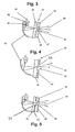
- Fig. 3 shows a section through the lamp 1, which is provided with the lens 20. It consists of two layers 22, 23, which are joined together, for example, in a multi-injection process to the lens 20.
- the opaque region 11 is a longitudinally extending strip-shaped light transmission area 25 provided. When spraying the one layer 22, the plastic penetrates into the light passage region 25, wherein a corresponding thickening 27 is formed. Subsequently, the outer layer 23 is injected onto the inner layer 22, the thickness of which corresponds at least approximately to the height of the thickening 27.
- the opaque region 11 has three strip-shaped, at a distance parallel to each other lying Licht manlass Symposiume 25. Accordingly, the inner layer 22 is provided with three thickened 27.
- the outer layer 23 consists in the exemplary embodiment of an opaque and semi-transparent, strongly colored material, which enters into a non-detachable connection with the inner layer 22 during the spraying process.
- the outside of the layer 23 and the end faces of the thickenings 27 form a continuous homogeneous flat surface on the finished lens 20.
- the inner layer 22 of the lens 20 is made of transparent material or dyed so that the light rays 24 can pass freely to the outside.
- On the outer side of the outer layer 23 of the lens 20 may reflective structures or other externally visible structures, such as the reflectors 18, be applied.
- a coating 34 is applied on the inner layer of the lens 20, a coating 34 is applied.
- the coating 34 is provided with interruptions 35.
- the inner layer 22 has no thickenings to form the regions 21.
- the coating 34 forms the outside of the lens 20 and may be a color coating or a foil coating.
- the embodiment is according to Fig. 4 the same as the one after Fig. 3 ,
- the areas 21 for the painting process must be masked.
- parts may be removed from the film to form the areas. These missing parts form the light-transmissive regions 21 after the film has been attached to the layer 22.
- the light emitted by the luminous means 31 is transmitted via the reflector 18 or directly (as described in connection with FIG Fig. 3 described) pass through the layer 22 and the light-transmissive regions 21 to the outside.
- the film 34 can be produced easily and inexpensively and applied to the layer 22. There is no expensive and expensive spraying required as in the embodiment of Fig. 3 ,
- Fig. 5 shows an embodiment in which the inner layer 22 of the lens 20 is formed the same as in the embodiment according to Fig. 3 ,
- the layer 22 has the thickening 27 to form the light-transmissive regions 21.
- the outer layer 23 is completely enveloped by the coating 34, which may be, for example, a color or foil coating.
- the outer layer 23 of the lens 20 is produced in a first step in a plastic injection molding process.
- the layer 23 is coated with the coating 34.
- the coated Part inserted into an injection mold, in which the inner layer 22 of the lens 20 is molded with the thickening 27.
- the inner layer 22 with the thickening 27 is advantageously made of transparent, colored transparent or different from the outer layer 23 material.
- the layer 22 with the thickening 27 is produced in a first injection molding process.
- the outer layer 23 provided with the coating 34 is then placed on the inner layer 22 and bonded to it by means of an adhesive or welding process.
- the coating 34 may be provided on the layer 22 and / or on the layer 23 with one or different structures. They can be used for better reflection within the luminaire 1.
- the coating 34 on the inner and on the outer layer 22, 23 may be formed in different materials and / or color designs.
Abstract
Description
Die Erfindung betrifft eine Leuchte für Fahrzeuge, vorzugsweise für Kraftfahrzeuge, nach dem Oberbegriff des Anspruches 1.The invention relates to a luminaire for vehicles, preferably for motor vehicles, according to the preamble of
Aus der
Der Erfindung liegt die Aufgabe zugrunde, die gattungsgemäße Leuchte so auszubilden, dass ihre geteilten Lichtfenster bei einfacher Ausgestaltung und kostengünstiger Herstellung in beleuchtetem Zustand als geschlossene Leuchtfläche wahrgenommen werden.The invention has for its object to design the generic lamp so that their split light windows are perceived in a simple design and cost-effective production in the illuminated state as a closed luminous area.
Diese Aufgabe wird bei der gattungsgemäßen Leuchte erfindungsgemäß mit den kennzeichnenden Merkmalen des Anspruches 1 gelöst.This object is achieved in the generic lamp according to the invention with the characterizing features of
Bei der erfindungsgemäßen Leuchte befindet sich im lichtundurchlässigen Bereich zwischen den beiden Lichtfenstern der zusätzliche lichtdurchlässige Bereich. Durch ihn wird erreicht, dass trotz des geteilten Lichtfensters ein vom Gesetzgeber gefordertes zusammenhängendes Lichtfenster für einen Betrachter erkennbar ist, wenn die beiden Lichtfenster die gleiche Lichtfunktion erfüllen. Der zusätzliche lichtdurchlässige Bereich kann klein sein. Er ist so im Zwischenbereich zwischen den Lichtfenstern angeordnet, dass ein Betrachter alle Lichtfenster als ein einziges Lichtfenster wahrnimmt. Die nichtleuchtenden Zwischenbereiche verschwimmen ab einem bestimmten Abstand im Auge des Betrachters, so dass er die Lichtfenster und den zusätzlichen lichtdurchlässigen Bereich nicht mehr als einzelne Lichtfenster wahrnimmt.In the luminaire according to the invention is located in the opaque area between the two light windows of the additional transparent area. It is achieved that, despite the split light window, a coherent light window required by the legislator can be recognized by a viewer if the two light windows have the same light function fulfill. The additional translucent area can be small. It is arranged in the intermediate area between the light windows so that a viewer perceives all the light windows as a single light window. The non-luminous intermediate areas blur at a certain distance in the eye of the beholder, so that he no longer perceives the light windows and the additional translucent area as a single light window.
Solche Lichtfenster in Leuchten sind dann von besonderem Interesse, wenn designrelevante Bereiche der Leuchte als ein Teil der Karosserie wirken sollen. Eine Aufteilung in einzelne Lichtfenster ist dann nicht mehr zu vermeiden. Als Alternative steht dann nur noch die Vergrößerung der Leuchte insgesamt zur Verfügung, da die gesetzlichen Mindestflächen der Lichtfunktionen der Leuchte zu erfüllen sind. Solche großen Leuchten sind jedoch aus ästhetischen Gründen nicht akzeptabel. Mit der erfindungsgemäßen Leuchte lassen sich die gesetzlichen Mindestflächen der Lichtfunktionen erfüllen, ohne dass die Leuchte insgesamt vergrößert werden muss.Such light windows in luminaires are of particular interest when design-relevant areas of the luminaire are to act as part of the bodywork. A division into individual light windows is then no longer avoidable. As an alternative, then only the enlargement of the lamp is available in total, since the legal minimum surfaces of the light functions of the lamp must be met. However, such large lights are unacceptable for aesthetic reasons. With the luminaire according to the invention, the legal minimum surfaces of the lighting functions can be fulfilled without the luminaire having to be enlarged overall.
Die erfindungsgemäße Leuchte hat ferner den Vorteil, dass sie sehr kostengünstig hergestellt werden kann, da im wesentlichen die gleichen Werkzeuge wie bei Standardleuchten zum Einsatz kommen können.The lamp according to the invention also has the advantage that it can be produced very inexpensively, since essentially the same tools as standard lamps can be used.
Weitere Merkmale der Erfindung ergeben sich aus den weiteren Ansprüchen, der Beschreibung und den Zeichnungen.Further features of the invention will become apparent from the other claims, the description and the drawings.
Die Erfindung wird anhand einiger in den Zeichnungen dargestellter Ausführungsformen näher erläutert. Es zeigt:
- Fig. 1
- eine Leuchte mit zwei voneinander getrennten Lichtfenstern für eine Leuchtenfunktion,
- Fig. 2
- eine erfindungsgemäße Leuchte mit voneinander getrennten Lichtfenstern, die durch einen Zwischenbereich voneinander getrennt sind, in dem streifenförmige Lichtdurchlassbereiche vorgesehen sind,
- Fig. 3
- in schematischer Darstellung einen Schnitt durch die Leuchte gemäß
Fig. 2 , - Fig. 4 und Fig. 5
- jeweils in Darstellungen entsprechend
Fig. 3 weitere Ausführungsformen von erfindungsgemäßen Leuchten.
- Fig. 1
- a luminaire with two separate light windows for a luminaire function,
- Fig. 2
- a luminaire according to the invention with separate light windows which are separated from one another by an intermediate region in which strip-shaped light transmission regions are provided,
- Fig. 3
- in a schematic representation of a section through the lamp according to
Fig. 2 . - 4 and FIG. 5
- respectively in representations accordingly
Fig. 3 further embodiments of lights according to the invention.
Beide Leuchtenteile 2, 3 weisen jeweils das obere Lichtfenster 6 und das untere Lichtfenster 7 auf, die jeweils durch einen lichtundurchlässigen bzw. teildurchlässigen Bereich 11 voneinander getrennt sind. Dieser ist im wesentlichen mittig zu den Leuchtenteilen 2, 3 angeordnet. Der Bereich 11 ist beispielsweise ein eingefärbter oder in der Wagenfarbe lackierter Teil einer Lichtscheibe 20, die die Leuchte 1 an einer Seite abschließt. Hinter dem Bereich 11 kann wenigstens ein Leuchtmittel 31 (
Das obere und das untere Lichtfenster 6 und 7 jedes Leuchtenteiles 2, 3 können innerhalb der Leuchte 1 miteinander verbunden sein. Zur Beleuchtung der Lichtfenster 6, 7 reicht ein einziges Leuchtmittel 31 aus, wenn dessen Licht über einen gemeinsamen Reflektor 30 zu den Lichtfenstern reflektiert wird. Ein außenstehender Betrachter hat dann den Eindruck, dass es sich um zwei einzelne Leuchten handelt. Selbstverständlich kann hinter dem Lichtfenster 6, 7 auch jeweils ein eigener Leuchtenbereich vorgesehen sein, der wenigstens ein Leuchtmittel 31 und wenigstens einen Reflektor 30 aufweist.The upper and
Den beiden Lichtfenstern 6, 7 der Leuchtenteile 2, 3 können gleiche Lichtfunktionen 15 und unterschiedliche Lichtfunktionen 15, 17 zugeordnet werden. Beispielsweise kann das obere Lichtfenster 6 des klappenseitigen Leuchtenteils 3 die gleiche Lichtfunktion 15 bis 17 haben wie das obere und das untere Lichtfenster 6, 7 des karosserieseitigen Leuchtenteiles 2. Das untere Lichtfenster 7 des klappenseitigen Leuchtenteiles 3 kann beispielsweise in zwei oder mehrere unterschiedliche Lichtfunktionen aufgeteilt sein. Die untere Hälfte kann beispielsweise als Nebelschlussleuchte 16 oder als Rückfahrlicht 19 ausgelegt sein. Die obere Hälfte dieses unteren Lichtfensters 7 kann beispielsweise einen Rückstrahlreflektor 18 bilden. Selbstverständlich sind bei diesen Lichtfunktionen die unterschiedlichsten Kombinationen und Verbindungen möglich.The two
Als eine weitere Kombinationsmöglichkeit können zum Beispiel die Lichtfenster 6, 7 des karosserieseitigen Leuchtenteiles 2 eine Mehrfachlichtfunktion aufweisen, wobei beispielsweise mit einem vorhandenen Schlusslicht 15 ein Fahrtrichtungsanzeiger 17 kombiniert sein kann. Bei einem entsprechend großen Abstand der oberen Lichtfenster 6 von den unteren Lichtfenstern 7 entsteht für einen außenstehenden Betrachter der Eindruck, dass es sich um zwei eigenständige Lichtfenster/Leuchten handelt.As a further possible combination, for example, the
Wie
Um diese Forderung bei einer solchen geteilten Leuchte zu erfüllen, sind gemäß
Hierbei ist es nötig und vom Gesetzgeber vorgeschrieben, dass der obere Rand des Bereiches 21 nicht mehr als 15 mm vom unteren Rand des oberen Lichtfensters 6 entfernt angeordnet ist. Dieselbe Bedingung gilt auch für die untere Kante des Bereiches 21, die einen Abstand von maximal 15 mm zur Oberkante des unteren Lichtfensters 7 haben muss. Durch diesen geringen Abstand wird sichergestellt, dass der rückseitig stehende Betrachter die aus einiger Entfernung betrachtete Leuchte 1 als durchgehendes Lichtfenster 6, 7, 21 wahrnimmt. Selbstverständlich kann der Bereich 21 auch als einteiliger Bereich ausgebildet sein. Besteht der Bereich 21, wie
Es ist nicht zwingend notwendig, dass die Bereiche 21 eine rechteckige Streifenform aufweisen. Es sind auch andere Formen möglich, vorausgesetzt, es entsteht der Eindruck, das obere und das untere Lichtfenster 6, 7 sind miteinander verbunden. Zum Beispiel können die Bereiche 21 Kreise sein oder elliptische oder gerundete, dreieckige oder mehreckige Formen aufweisen.It is not absolutely necessary that the
Die Bereiche 21 können wie die einzelnen Lichtfenster 6, 7 mehrere unterschiedliche Lichtfunktionen aufweisen. Es kann zum Beispiel im oberen Lichtfensterbereich das Lichtfenster 6 als Schlusslicht 15 mit einem teilabgrenzenden Bereich als Fahrtrichtungsanzeiger 17 ausgebildet sein, während das untere Lichtfenster 7 beispielsweise ausschließlich als Schlusslicht 15 dient. Die Bereiche 21 können in diesem Fall als Fahrtrichtungsanzeiger 17 und/oder als Schlusslicht 15 betrieben werden. Die Verwendung derartiger Bereiche 21 ist nicht nur auf den karosserieseitigen Leuchtenteil 2 beschränkt. Selbstverständlich kann auch der klappenseitige Leuchtenteil 3 solche Bereiche 21 aufweisen.The
Als zusätzliches Designelement können streifenförmige Bereiche 21 im äußeren Randbereich der zwei Leuchtenteile 2, 3 angeordnet sein. Hierbei entsteht der Effekt, dass die Leuchte 1 als geschlossener Rahmen erscheint.As an additional design element, strip-shaped
Lichtstrahlen 27, die vom Leuchtmittel 31 ausgesandt und über den Reflektor 30 auf den rückwärtigen Bereich der Schicht 22 reflektiert werden, können in den Bereichen, in denen sich die äußere Schicht 23 befindet, nicht durch die Lichtscheibe 20 nach außen treten. Allenfalls werden die Lichtstrahlen 24 zum Reflektor 30 zurück reflektiert. Die Strahlen 24 werden solange hin- und herreflektiert bis sie auf eine der Verdickungen 27 treffen, die die lichtdurchlässigen Bereiche 21 bilden. In diesen Bereichen können die Lichtstrahlen 24 durch die Lichtscheibe 20 hindurch nach außen treten (
Auf der äußeren Seite der äußeren Schicht 23 der Lichtscheibe 20 können reflektierende Strukturen oder sonstige von außen erkennbare Strukturen, wie beispielsweise die Reflektoren 18, aufgebracht sein.On the outer side of the
Beim Ausführungsbeispiel gemäß
Besteht die Beschichtung 34 aus einer Farbbeschichtung, müssen die Bereiche 21 für das Lackierverfahren maskiert werden. Bei einer Folienbeschichtung können zur Bildung der Bereiche 21 Teile aus der Folie entfernt sein. Diese fehlenden Teile bilden nach der Befestigung der Folie auf der Schicht 22 die lichtdurchlässigen Bereiche 21. Das vom Leuchtmittel 31 abgestrahlte Licht wird über den Reflektor 18 oder direkt (wie anhand von
Die Folie 34 lässt sich einfach und kostengünstig herstellen und auf die Schicht 22 aufbringen. Es ist kein aufwändiges und teures Spritzverfahren erforderlich wie beim Ausführungsbeispiel nach
Die äußere Schicht 23 der Lichtscheibe 20 wird in einem ersten Schritt in einem Kunststoffspritzverfahren hergestellt. In einem zweiten Schritt wird die Schicht 23 mit der Beschichtung 34 umhüllt. Anschließend wird das beschichtete Teil in ein Spritzgießwerkzeug eingelegt, in dem die innere Schicht 22 der Lichtscheibe 20 mit der Verdickung 27 angespritzt wird. Die innere Schicht 22 mit der Verdickung 27 besteht vorteilhaft aus transparentem, eingefärbtem transparenten oder einem von der äußeren Schicht 23 unterschiedlichen Material.The
Bei einer anderen Herstellungsweise wird die Schicht 22 mit der Verdickung 27 in einem ersten Spritzgießverfahren hergestellt. Die mit der Beschichtung 34 versehene äußere Schicht 23 wird dann auf die innere Schicht 22 aufgelegt und mit ihr mittels eines Klebe- oder Schweißverfahrens verbunden. Die Beschichtung 34 kann auf der Schicht 22 und/oder auf der Schicht 23 mit einer oder unterschiedlichen Strukturen versehen sein. Sie können für eine bessere Reflektion innerhalb der Leuchte 1 genutzt werden. Die Beschichtung 34 auf der inneren und auf der äußeren Schicht 22, 23 kann in unterschiedlichen Materialien und/oder Farbgestaltungen ausgebildet sein.In another method of production, the
Claims (13)
dadurch gekennzeichnet, dass im lichtundurchlässigen Bereich (11) wenigstens ein zusätzlicher lichtdurchlässiger Bereich (21) vorgesehen ist.Luminaire for vehicles, preferably for motor vehicles, with a housing and a lens behind which provided at least one light source and which is divided into at least two separate translucent and spaced light windows having the same or different lighting functions and between which at least one at least partially opaque area is present,
characterized in that in the opaque region (11) at least one additional light-transmissive region (21) is provided.
dadurch gekennzeichnet, dass der lichtdurchlässige Bereich (21) streifenförmig ausgebildet ist oder runden, unrunden oder eckigen Umriss hat.Luminaire according to claim 1,
characterized in that the translucent region (21) is strip-shaped or has round, non-circular or angular outline.
dadurch gekennzeichnet, dass der Abstand zwischen den Rändern der Lichtfenster (6, 7) und dem zusätzlichen lichtdurchlässigen Bereich (21) kleiner ist als etwa 15 mm.Luminaire according to claim 1 or 2,
characterized in that the distance between the edges of the light windows (6, 7) and the additional translucent area (21) is less than about 15 mm.
dadurch gekennzeichnet, dass der Abstand zwischen den Rändern von wenigstens zwei mit Abstand voneinander liegenden lichtdurchlässigen Bereichen (21) kleiner ist als etwa 15 mm.Luminaire according to one of claims 1 to 3,
characterized in that the distance between the edges of at least two spaced translucent areas (21) is less than about 15 mm.
dadurch gekennzeichnet, dass dem lichtdurchlässigen Bereich (21) und den Lichtfenstern (6, 7) eine gemeinsame oder jeweils wenigstens eine Lichtquelle (31) zugeordnet ist.Luminaire according to one of claims 1 to 4,
characterized in that the light-transmissive region (21) and the light windows (6, 7) is associated with a common or at least one light source (31).
dadurch gekennzeichnet, dass der lichtdurchlässige Bereich (21) in einer von den Lichtfenstern (6, 7) abweichenden Farbe leuchtet, und dass vorteilhaft den Lichtfenstern (6, 7) im Innern der Leuchte (1) ein gemeinsamer Reflektor (30) oder jedem Lichtfenster (6, 7) ein Reflektor (30) zugeordnet ist.Luminaire according to one of claims 1 to 5,
characterized in that the translucent area (21) in one of the light windows (6, 7) different color lights, and that advantageously the light windows (6, 7) inside the lamp (1) has a common reflector (30) or each light window (6, 7) is associated with a reflector (30).
dadurch gekennzeichnet, dass die Lichtscheibe (20) aus wenigstens zwei Schichten (22, 23) besteht.Luminaire, in particular according to one of claims 1 to 6,
characterized in that the lens (20) consists of at least two layers (22, 23).
dadurch gekennzeichnet, dass eine äußere Schicht (23) der Lichtscheibe (20) im lichtdurchlässigen Bereich (21) unterbrochen und vorteilhaft für Lichtstrahlen (24) des Leuchtmittels (31) undurchlässig oder durchlässig ist.Luminaire according to claim 7,
characterized in that an outer layer (23) of the lens (20) in the light-transmitting region (21) is interrupted and advantageous for light beams (24) of the lighting means (31) is impermeable or permeable.
dadurch gekennzeichnet, dass eine innere Schicht (22) der Lichtscheibe (20) mindestens eine Verdickung (27) aufweist, die in die Unterbrechung der äußeren Schicht (23) eingreift.Luminaire according to claim 8,
characterized in that an inner layer (22) of the lens (20) has at least one thickening (27) which engages in the interruption of the outer layer (23).
dadurch gekennzeichnet, dass die äußere Schicht (23) der Lichtscheibe (20) mittels eines Mehrschicht-Spritzverfahrens auf die innere Schicht (22) aufgebracht ist.Luminaire according to one of claims 7 to 9,
characterized in that the outer layer (23) of the lens (20) is applied to the inner layer (22) by means of a multi-layer spraying process.
dadurch gekennzeichnet, dass die Verdickung (27) der inneren Schicht (22) aus einem anderen Material besteht und/oder eine andere Farbe als die innere Schicht (22) aufweist.Luminaire according to claim 9 or 10,
characterized in that the thickening (27) of the inner layer (22) is made of a different material and / or has a different color than the inner layer (22).
dadurch gekennzeichnet, dass die äußere Schicht (23) der Lichtscheibe (20) mit einer umhüllenden Beschichtung (34) versehen ist, die vorteilhaft eine Lackbeschichtung oder eine Folienbeschichtung ist.Luminaire according to one of claims 7 to 11,
characterized in that the outer layer (23) of the lens (20) is provided with an enveloping coating (34) which is advantageously a paint coating or a film coating.
dadurch gekennzeichnet, dass die Stirnseite der Verdickung (27) der inneren Schicht (22) und die Außenseite der äußeren Schicht (23) der Lichtscheibe (20) im Wesentlichen bündig liegen, und dass vorteilhaft die Verdickung (27) der inneren Schicht (22) eine Optik oder eine optische Struktur aufweist.Luminaire according to one of claims 9 to 12,
characterized in that the end face of the thickening (27) of the inner layer (22) and the outer side of the outer layer (23) of the lens (20) are substantially flush, and that advantageously the thickening (27) of the inner layer (22) has an optic or an optical structure.
Priority Applications (1)
| Application Number | Priority Date | Filing Date | Title |
|---|---|---|---|
| SI200830013T SI1950492T1 (en) | 2007-01-25 | 2008-01-19 | Lamp for vehicles, in particular motor vehicles |
Applications Claiming Priority (1)
| Application Number | Priority Date | Filing Date | Title |
|---|---|---|---|
| DE102007005551A DE102007005551A1 (en) | 2007-01-25 | 2007-01-25 | Luminaire for vehicles, preferably for motor vehicles |
Publications (2)
| Publication Number | Publication Date |
|---|---|
| EP1950492A1 true EP1950492A1 (en) | 2008-07-30 |
| EP1950492B1 EP1950492B1 (en) | 2009-12-02 |
Family
ID=39283905
Family Applications (1)
| Application Number | Title | Priority Date | Filing Date |
|---|---|---|---|
| EP08000996A Expired - Fee Related EP1950492B1 (en) | 2007-01-25 | 2008-01-19 | Lamp for vehicles, in particular motor vehicles |
Country Status (4)
| Country | Link |
|---|---|
| US (1) | US20080180970A1 (en) |
| EP (1) | EP1950492B1 (en) |
| DE (2) | DE102007005551A1 (en) |
| SI (1) | SI1950492T1 (en) |
Cited By (11)
| Publication number | Priority date | Publication date | Assignee | Title |
|---|---|---|---|---|
| EP2020565A1 (en) * | 2007-08-02 | 2009-02-04 | odelo GmbH | Lamp |
| WO2015079184A1 (en) * | 2013-11-29 | 2015-06-04 | Peugeot Citroen Automobiles Sa | Plastic rear window for a motor vehicle, provided with a third break light |
| FR3014787A1 (en) * | 2013-12-12 | 2015-06-19 | Peugeot Citroen Automobiles Sa | LIGHT SIGNALING DIPOSITIVE |
| WO2017042703A1 (en) * | 2015-09-07 | 2017-03-16 | Sabic Global Technologies B.V. | Lighting systems of tailgates with plastic glazing |
| FR3046579A1 (en) * | 2016-01-11 | 2017-07-14 | Peugeot Citroen Automobiles Sa | OPTICAL BLOCK COMPRISING A SIGNALING LIGHT WITH A FLAT LIGHT GUIDE OF ITS EXTERIOR ICE |
| DE102017105948A1 (en) | 2016-03-23 | 2017-09-28 | Varroc Lighting Systems, s.r.o. | A lighting device, in particular a signal light for motor vehicles |
| US10434846B2 (en) | 2015-09-07 | 2019-10-08 | Sabic Global Technologies B.V. | Surfaces of plastic glazing of tailgates |
| US10597097B2 (en) | 2015-09-07 | 2020-03-24 | Sabic Global Technologies B.V. | Aerodynamic features of plastic glazing of tailgates |
| CN112092722A (en) * | 2020-08-31 | 2020-12-18 | 江苏大学 | Hierarchical lighting type braking warning tail lamp based on vehicle-mounted radar |
| US11267173B2 (en) | 2015-09-07 | 2022-03-08 | Sabic Global Technologies B.V. | Molding of plastic glazing of tailgates |
| US11466834B2 (en) | 2015-11-23 | 2022-10-11 | Sabic Global Technologies B.V. | Lighting systems for windows having plastic glazing |
Families Citing this family (9)
| Publication number | Priority date | Publication date | Assignee | Title |
|---|---|---|---|---|
| DE102011111994B3 (en) | 2011-08-31 | 2012-07-12 | Volkswagen Aktiengesellschaft | Lighting device for a vehicle with a multi-layered lens |
| DE102011119379A1 (en) * | 2011-11-25 | 2013-05-29 | Volkswagen Aktiengesellschaft | Lighting device for a motor vehicle |
| DE102012015265B4 (en) | 2012-08-01 | 2023-11-16 | Volkswagen Aktiengesellschaft | Cover lens for a vehicle light |
| DE102012025936B3 (en) | 2012-08-01 | 2024-02-08 | Volkswagen Aktiengesellschaft | Cover lens for a vehicle light |
| CN106104144B (en) | 2014-03-12 | 2020-01-17 | 大众汽车有限公司 | Motor vehicle and motor vehicle headlight with an additional housing |
| AT520400B1 (en) * | 2017-08-29 | 2020-10-15 | Zkw Group Gmbh | LIGHTING AND / OR SIGNALING DEVICE FOR A MOTOR VEHICLE |
| DE102017120951B4 (en) * | 2017-09-11 | 2019-05-16 | Preh Gmbh | Luminaire with structure or decor and related manufacturing processes |
| ES2710076B2 (en) | 2017-10-17 | 2020-06-08 | Seat Sa | Exterior lighting device for a vehicle, and manufacturing method |
| DE102021201145A1 (en) | 2021-02-08 | 2022-08-11 | Volkswagen Aktiengesellschaft | Motor vehicle headlight and method for operating a motor vehicle headlight |
Citations (4)
| Publication number | Priority date | Publication date | Assignee | Title |
|---|---|---|---|---|
| US4855877A (en) * | 1987-12-01 | 1989-08-08 | Koito Seisakusho Co., Ltd. | Combination lamp assembly of monochromatic appearance capable of glowing in different colors |
| EP0442095A2 (en) * | 1990-02-13 | 1991-08-21 | Hella KG Hueck & Co. | Rearlight for vehicles |
| FR2775229A1 (en) * | 1998-02-20 | 1999-08-27 | Valeo Vision | Automobile rear light cluster |
| DE19811570C2 (en) | 1998-03-17 | 2001-08-02 | Volkswagen Ag | Vehicle headlights with a housing and a lens for a glare-free signal image function |
Family Cites Families (5)
| Publication number | Priority date | Publication date | Assignee | Title |
|---|---|---|---|---|
| US1397822A (en) * | 1920-10-14 | 1921-11-22 | Chauncey G Peters | Headlight diffraction-lens |
| FR2755077B1 (en) * | 1996-10-25 | 1999-01-08 | Valeo Vision | SIGNAL LIGHT, PARTICULARLY FOR VEHICLES, WITH IMPROVED EXTINGUISHED APPEARANCE |
| DE29717698U1 (en) * | 1997-10-04 | 1997-11-13 | Reitter & Schefenacker Gmbh | Light windows for signal lights, in particular for motor vehicle rear lights |
| JP4030804B2 (en) * | 2002-06-07 | 2008-01-09 | 株式会社小糸製作所 | Vehicle lamp |
| JP2004319347A (en) * | 2003-04-18 | 2004-11-11 | Koito Mfg Co Ltd | Lens of vehicular lighting fitting |
-
2007
- 2007-01-25 DE DE102007005551A patent/DE102007005551A1/en not_active Ceased
-
2008
- 2008-01-19 EP EP08000996A patent/EP1950492B1/en not_active Expired - Fee Related
- 2008-01-19 SI SI200830013T patent/SI1950492T1/en unknown
- 2008-01-19 DE DE502008000217T patent/DE502008000217D1/en active Active
- 2008-01-25 US US12/020,084 patent/US20080180970A1/en not_active Abandoned
Patent Citations (4)
| Publication number | Priority date | Publication date | Assignee | Title |
|---|---|---|---|---|
| US4855877A (en) * | 1987-12-01 | 1989-08-08 | Koito Seisakusho Co., Ltd. | Combination lamp assembly of monochromatic appearance capable of glowing in different colors |
| EP0442095A2 (en) * | 1990-02-13 | 1991-08-21 | Hella KG Hueck & Co. | Rearlight for vehicles |
| FR2775229A1 (en) * | 1998-02-20 | 1999-08-27 | Valeo Vision | Automobile rear light cluster |
| DE19811570C2 (en) | 1998-03-17 | 2001-08-02 | Volkswagen Ag | Vehicle headlights with a housing and a lens for a glare-free signal image function |
Cited By (22)
| Publication number | Priority date | Publication date | Assignee | Title |
|---|---|---|---|---|
| EP2020565A1 (en) * | 2007-08-02 | 2009-02-04 | odelo GmbH | Lamp |
| CN105793110B (en) * | 2013-11-29 | 2018-09-21 | 标致雪铁龙集团 | Rear window made of plastic material for the motor vehicle equipped with third brake lamp |
| WO2015079184A1 (en) * | 2013-11-29 | 2015-06-04 | Peugeot Citroen Automobiles Sa | Plastic rear window for a motor vehicle, provided with a third break light |
| FR3014033A1 (en) * | 2013-11-29 | 2015-06-05 | Peugeot Citroen Automobiles Sa | PLASTIC REAR WINDOW FOR MOTOR VEHICLE EQUIPPED WITH A THIRD STOP FIRE |
| CN105793110A (en) * | 2013-11-29 | 2016-07-20 | 标致雪铁龙集团 | Plastic rear window for a motor vehicle, provided with a third break light |
| FR3014787A1 (en) * | 2013-12-12 | 2015-06-19 | Peugeot Citroen Automobiles Sa | LIGHT SIGNALING DIPOSITIVE |
| US10434846B2 (en) | 2015-09-07 | 2019-10-08 | Sabic Global Technologies B.V. | Surfaces of plastic glazing of tailgates |
| US10690314B2 (en) | 2015-09-07 | 2020-06-23 | Sabic Global Technologies B.V. | Lighting systems of tailgates with plastic glazing |
| US11845240B2 (en) | 2015-09-07 | 2023-12-19 | Sabic Global Technologies B.V. | Three shot plastic tailgate |
| US11458709B2 (en) | 2015-09-07 | 2022-10-04 | Sabic Global Technologies B.V. | Three shot plastic tailgate |
| WO2017042703A1 (en) * | 2015-09-07 | 2017-03-16 | Sabic Global Technologies B.V. | Lighting systems of tailgates with plastic glazing |
| US11267173B2 (en) | 2015-09-07 | 2022-03-08 | Sabic Global Technologies B.V. | Molding of plastic glazing of tailgates |
| US10597097B2 (en) | 2015-09-07 | 2020-03-24 | Sabic Global Technologies B.V. | Aerodynamic features of plastic glazing of tailgates |
| US10948152B2 (en) | 2015-09-07 | 2021-03-16 | Sabic Global Technologies B.V. | Lighting systems of tailgates with plastic glazing |
| US10717348B2 (en) | 2015-09-07 | 2020-07-21 | Sabic Global Technologies B.V. | Surfaces of plastic glazing of tailgates |
| US11466834B2 (en) | 2015-11-23 | 2022-10-11 | Sabic Global Technologies B.V. | Lighting systems for windows having plastic glazing |
| US11766965B2 (en) | 2015-11-23 | 2023-09-26 | Sabic Global Technologies B.V. | Illuminated graphic in an automotive plastic glazing |
| WO2017121944A1 (en) * | 2016-01-11 | 2017-07-20 | Peugeot Citroen Automobiles Sa | Optical unit including a signaling light having a flat light guide projecting from the outer lens |
| FR3046579A1 (en) * | 2016-01-11 | 2017-07-14 | Peugeot Citroen Automobiles Sa | OPTICAL BLOCK COMPRISING A SIGNALING LIGHT WITH A FLAT LIGHT GUIDE OF ITS EXTERIOR ICE |
| US10458617B2 (en) | 2016-03-23 | 2019-10-29 | Varroc Lighting Systems, s.r.o. | Light device, especially a signal lamp for motor vehicles |
| DE102017105948A1 (en) | 2016-03-23 | 2017-09-28 | Varroc Lighting Systems, s.r.o. | A lighting device, in particular a signal light for motor vehicles |
| CN112092722A (en) * | 2020-08-31 | 2020-12-18 | 江苏大学 | Hierarchical lighting type braking warning tail lamp based on vehicle-mounted radar |
Also Published As
| Publication number | Publication date |
|---|---|
| DE502008000217D1 (en) | 2010-01-14 |
| SI1950492T1 (en) | 2010-03-31 |
| DE102007005551A1 (en) | 2008-07-31 |
| EP1950492B1 (en) | 2009-12-02 |
| US20080180970A1 (en) | 2008-07-31 |
Similar Documents
| Publication | Publication Date | Title |
|---|---|---|
| EP1950492B1 (en) | Lamp for vehicles, in particular motor vehicles | |
| EP1914118B1 (en) | External rear mirror with illumination device | |
| DE102011016002B3 (en) | Lighting device with closed mold for a motor vehicle | |
| DE102006059980A1 (en) | Illuminating unit for car, has three light conductors including front sides for coupling light from light sources, where another front sides of light conductors serve as light emission surface | |
| EP1737701A1 (en) | Exterior rearview mirror for vehicles, especially for motor vehicles | |
| DE102011016433A1 (en) | Sunroof for motor vehicle e.g. motor car, has transparent light conductor plate arranged on roof frame and arranged in portion of roof opening, where light-scattering nano-particles are arranged in volume part of light conductor plate | |
| EP1757857A1 (en) | Vehicle lamp | |
| EP2639107B1 (en) | Lighting device, in particular contour illumination for a motor vehicle | |
| DE102018213317A1 (en) | Light guide and vehicle light | |
| DE102008056985A1 (en) | Decorative lamp unit for motor vehicle, is provided with luminous element for generating light beam and lens through which light beam is radiated | |
| DE112018000109T5 (en) | Vehicle lamp with a three-dimensional light effect, its application method and vehicle | |
| DE102009058788A1 (en) | Rear window for motor vehicle, has light source and lighting device with optically effective element that is enclosed by transparent material i.e. polycarbonate, where window is partially made of transparent material | |
| DE102016205408A1 (en) | Luminaire for a motor vehicle | |
| DE10124539B4 (en) | Tail light for vehicles, especially for motor vehicles | |
| DE102007033706A1 (en) | Vehicle lighting device consists of lighting device that has housing with chamber in which light source is located with colour changing light disc | |
| DE102014104891A1 (en) | License plate lighting device with multiple layers | |
| DE10341572B4 (en) | Vehicle lamp with electroluminescent arrangement | |
| DE10337615B3 (en) | Lighting device for vehicles | |
| DE4005417C1 (en) | Lamp cover for motor vehicle tail light cluster - is integral piece with bendable region(s) allowing bowing to fit assembly contour | |
| DE4324036C2 (en) | Motor vehicle rear light with improved appearance | |
| DE102018009248A1 (en) | Light for a motor vehicle | |
| EP3792111B1 (en) | Lamp | |
| DE102018220623A1 (en) | Lamp arrangement for a vehicle | |
| EP3814172B1 (en) | Method for producing a blinker module, blinker module, rear-view device, and motor vehicle | |
| DE102004062919A1 (en) | Reflector for motor vehicle, has reflection unit with reflection surface, where reflection unit is connected with cover layer that lies at a distance behind light pane which is provided with illuminated optics at its inner side |
Legal Events
| Date | Code | Title | Description |
|---|---|---|---|
| PUAI | Public reference made under article 153(3) epc to a published international application that has entered the european phase |
Free format text: ORIGINAL CODE: 0009012 |
|
| AK | Designated contracting states |
Kind code of ref document: A1 Designated state(s): AT BE BG CH CY CZ DE DK EE ES FI FR GB GR HR HU IE IS IT LI LT LU LV MC MT NL NO PL PT RO SE SI SK TR |
|
| AX | Request for extension of the european patent |
Extension state: AL BA MK RS |
|
| 17P | Request for examination filed |
Effective date: 20081121 |
|
| RAP1 | Party data changed (applicant data changed or rights of an application transferred) |
Owner name: ODELO GMBH |
|
| AKX | Designation fees paid |
Designated state(s): DE FR IT SI |
|
| GRAP | Despatch of communication of intention to grant a patent |
Free format text: ORIGINAL CODE: EPIDOSNIGR1 |
|
| GRAS | Grant fee paid |
Free format text: ORIGINAL CODE: EPIDOSNIGR3 |
|
| GRAA | (expected) grant |
Free format text: ORIGINAL CODE: 0009210 |
|
| AK | Designated contracting states |
Kind code of ref document: B1 Designated state(s): DE FR IT SI |
|
| REF | Corresponds to: |
Ref document number: 502008000217 Country of ref document: DE Date of ref document: 20100114 Kind code of ref document: P |
|
| PLBE | No opposition filed within time limit |
Free format text: ORIGINAL CODE: 0009261 |
|
| STAA | Information on the status of an ep patent application or granted ep patent |
Free format text: STATUS: NO OPPOSITION FILED WITHIN TIME LIMIT |
|
| 26N | No opposition filed |
Effective date: 20100903 |
|
| PGFP | Annual fee paid to national office [announced via postgrant information from national office to epo] |
Ref country code: IT Payment date: 20120123 Year of fee payment: 5 |
|
| PGFP | Annual fee paid to national office [announced via postgrant information from national office to epo] |
Ref country code: FR Payment date: 20130213 Year of fee payment: 6 |
|
| PGFP | Annual fee paid to national office [announced via postgrant information from national office to epo] |
Ref country code: SI Payment date: 20130107 Year of fee payment: 6 |
|
| REG | Reference to a national code |
Ref country code: SI Ref legal event code: KO00 Effective date: 20140910 |
|
| REG | Reference to a national code |
Ref country code: FR Ref legal event code: ST Effective date: 20140930 |
|
| PG25 | Lapsed in a contracting state [announced via postgrant information from national office to epo] |
Ref country code: SI Free format text: LAPSE BECAUSE OF NON-PAYMENT OF DUE FEES Effective date: 20140120 Ref country code: FR Free format text: LAPSE BECAUSE OF NON-PAYMENT OF DUE FEES Effective date: 20140131 |
|
| REG | Reference to a national code |
Ref country code: DE Ref legal event code: R082 Ref document number: 502008000217 Country of ref document: DE Representative=s name: PATENTANWALTSKANZLEI MEYER, DE |
|
| REG | Reference to a national code |
Ref country code: DE Ref legal event code: R081 Ref document number: 502008000217 Country of ref document: DE Owner name: ODELO GMBH, DE Free format text: FORMER OWNER: ODELO GMBH, 71409 SCHWAIKHEIM, DE Effective date: 20150422 Ref country code: DE Ref legal event code: R082 Ref document number: 502008000217 Country of ref document: DE Representative=s name: PATENTANWALTSKANZLEI MEYER, DE Effective date: 20150422 |
|
| PGFP | Annual fee paid to national office [announced via postgrant information from national office to epo] |
Ref country code: DE Payment date: 20160120 Year of fee payment: 9 |
|
| PG25 | Lapsed in a contracting state [announced via postgrant information from national office to epo] |
Ref country code: IT Free format text: LAPSE BECAUSE OF NON-PAYMENT OF DUE FEES Effective date: 20140119 |
|
| REG | Reference to a national code |
Ref country code: DE Ref legal event code: R119 Ref document number: 502008000217 Country of ref document: DE |
|
| PG25 | Lapsed in a contracting state [announced via postgrant information from national office to epo] |
Ref country code: DE Free format text: LAPSE BECAUSE OF NON-PAYMENT OF DUE FEES Effective date: 20170801 |