EP1950440B2 - Verfahren zur Herstellung eines Kupplungskorbes einer Doppelkupplung - Google Patents
Verfahren zur Herstellung eines Kupplungskorbes einer Doppelkupplung Download PDFInfo
- Publication number
- EP1950440B2 EP1950440B2 EP07001761.1A EP07001761A EP1950440B2 EP 1950440 B2 EP1950440 B2 EP 1950440B2 EP 07001761 A EP07001761 A EP 07001761A EP 1950440 B2 EP1950440 B2 EP 1950440B2
- Authority
- EP
- European Patent Office
- Prior art keywords
- clutch
- drum
- sheet metal
- metal strip
- cage
- Prior art date
- Legal status (The legal status is an assumption and is not a legal conclusion. Google has not performed a legal analysis and makes no representation as to the accuracy of the status listed.)
- Not-in-force
Links
Images
Classifications
-
- F—MECHANICAL ENGINEERING; LIGHTING; HEATING; WEAPONS; BLASTING
- F16—ENGINEERING ELEMENTS AND UNITS; GENERAL MEASURES FOR PRODUCING AND MAINTAINING EFFECTIVE FUNCTIONING OF MACHINES OR INSTALLATIONS; THERMAL INSULATION IN GENERAL
- F16D—COUPLINGS FOR TRANSMITTING ROTATION; CLUTCHES; BRAKES
- F16D13/00—Friction clutches
- F16D13/58—Details
- F16D13/60—Clutching elements
- F16D13/64—Clutch-plates; Clutch-lamellae
- F16D13/68—Attachments of plates or lamellae to their supports
- F16D13/683—Attachments of plates or lamellae to their supports for clutches with multiple lamellae
-
- F—MECHANICAL ENGINEERING; LIGHTING; HEATING; WEAPONS; BLASTING
- F16—ENGINEERING ELEMENTS AND UNITS; GENERAL MEASURES FOR PRODUCING AND MAINTAINING EFFECTIVE FUNCTIONING OF MACHINES OR INSTALLATIONS; THERMAL INSULATION IN GENERAL
- F16D—COUPLINGS FOR TRANSMITTING ROTATION; CLUTCHES; BRAKES
- F16D21/00—Systems comprising a plurality of actuated clutches
- F16D21/02—Systems comprising a plurality of actuated clutches for interconnecting three or more shafts or other transmission members in different ways
- F16D21/06—Systems comprising a plurality of actuated clutches for interconnecting three or more shafts or other transmission members in different ways at least two driving shafts or two driven shafts being concentric
- F16D2021/0676—Mechanically actuated multiple lamellae clutches
-
- F—MECHANICAL ENGINEERING; LIGHTING; HEATING; WEAPONS; BLASTING
- F16—ENGINEERING ELEMENTS AND UNITS; GENERAL MEASURES FOR PRODUCING AND MAINTAINING EFFECTIVE FUNCTIONING OF MACHINES OR INSTALLATIONS; THERMAL INSULATION IN GENERAL
- F16D—COUPLINGS FOR TRANSMITTING ROTATION; CLUTCHES; BRAKES
- F16D2250/00—Manufacturing; Assembly
Definitions
- the invention relates to a method for producing a clutch basket of a dual clutch.
- a clutch basket and a method for its preparation are known from DE-B-103 19 703 known, which represents the closest prior art.
- Dual-clutch transmissions are increasingly being used in automotive construction due to their numerous advantages.
- a key element of this type of transmission is the wet or dry dual clutch, which directs the engine torque to one of the two partial transmission. While one clutch is closed, the other is open.
- the clutch basket in contrast to the prior art, according to which the basket is made in one piece, is not made in one piece, but the toothing is produced separately from the rest of the basket. Subsequently, the toothing is fixed to the basket, for example, welded, caulked or otherwise secured.
- the teeth to form the basket during assembly of the coupling is connected to the outer clutch housing.
- the toothing is produced by rolling a sheet metal strip.
- the rollers have the shape of the later desired toothing.
- an endless strip of toothing is generated, which is limited only by the length of the sheet metal blank.
- additional holes or recesses e.g. For oil supply to the clutch, or even notches, special noses, bulges, etc. required for mounting purposes or the like, this is also possible by a corresponding form of the rolls of the method according to the invention in a simple technical way.
- such holes etc. can be easily punched or inserted in the endless strip with conventional punching machines.
- the aforementioned noses, holes, etc. in contrast, are possible in conventional known deep-drawing only by a further operation.
- the endless toothing strip produced in accordance with the method according to the invention is cut off after insertion of the toothing in the required length and rolled up into a drum.
- the butt ends are joined together as required by suitable bonding methods such as laser welding, spot welding, caulking correspondingly shaped ends, or other suitable bonding methods.
- suitable bonding methods such as laser welding, spot welding, caulking correspondingly shaped ends, or other suitable bonding methods.
- This then creates the required toothed drum, which is attached depending on the application, for example, either on a metal plate, creating a complete pot, or, as in previously mentioned couplings according to the US 7,121,392 , is connected directly to the coupling housing.
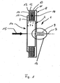
- Fig. 1 is schematically simplified a dual clutch 1 of a dual clutch transmission shown in Fig. 1 to simplify the description is not shown.
- the double clutch 1 has an inner clutch 2 which is connected to an inner shaft 3.
- the inner clutch 2 has a plate carrier 7, which is provided with inner fins, wherein in the in Fig. 1 illustrated embodiment, three inner plates 4, 5 and 6 are exemplified.
- the double clutch 1 further comprises an outer clutch 8, which is provided with an outer shaft 9, which is formed as a hollow shaft and in which the inner shaft 3 extends coaxially, which is shown in detail from the illustration of Fig. 1 results.
- the outer, connected to the outer shaft 9 clutch 8 has an outer plate carrier 10 which is provided with outer ßeren fins, wherein according to the in Fig. 1 illustrated embodiment, three outer plates 11, 12 and 13 are provided by way of example.
- the dual clutch 1 a drive part 14 which is arranged on a symbolized by the arrow 15 drive shaft.
- the drive member 14 has inner and outer drive blades, wherein in the exemplary case five outer and five inner drive plates are provided, of which an outer drive plate with the reference numeral 16 and one of the inner drive plates with the reference numeral 17 in Fig. 1 are representative of all drive plates are marked.
- Fig. 1 illustrates that the inner and outer drive plates 17 and 16 are arranged or fixed on a single plate basket 18, which is arranged between the inner and outer plate carrier 7 and 10 respectively.
- the provision of such a single finned basket 18 significantly reduces the size of the double clutch 1 according to the invention, which results in the advantages explained above.
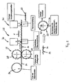
- Fig. 2 is a manufacturing device 25 according to the invention for carrying out a method according to the invention for producing a clutch basket of a double clutch, as in Fig. 1 explained dual clutch 1, shown.
- the device 25 initially has a feeding device 26, which in the in Fig. 2 simplified embodiment comprises a coil with a metal strip 21. Viewed in the conveying direction F of the sheet metal strip 21, a rolling device 27 or a roll stand is provided after the feeder 26, which in the in Fig. 2 simplified embodiment shown two rollers 28 and 29, which are arranged on both sides of the sheet-metal strip 21. How out Fig. 2 can be seen, the rollers 28 and 29 on an outer contouring, which in the course of rolling of the sheet metal strip 21, the teeth 27 mounted in the sheet metal strip 21 after the rolling device 27. After the rolling device 27, an optional or additional punching device 30 is provided with which it is possible, for example, to attach holes or recesses in the toothed sheet metal strip 21. Furthermore, the device 25 has a separating device 31, with the finished toothed strip 22 can be separated in the particular desired length.
- Fig. 2 illustrates that this bending to the finished drum 23 results in a drum having an outer toothing 32 and an inner toothing 33.
- This drum 23 can then be further processed into a lamella basket by having a in Fig. 2 not shown metal plate is connected.
- toothed drum 23 with a in Fig. 2 also not shown coupling housing to connect.
Landscapes
- Engineering & Computer Science (AREA)
- General Engineering & Computer Science (AREA)
- Mechanical Engineering (AREA)
- Mechanical Operated Clutches (AREA)
- Hydraulic Clutches, Magnetic Clutches, Fluid Clutches, And Fluid Joints (AREA)
Description
- Die Erfindung betrifft ein Verfahren zur Herstellung eines Kupplungskorbes einer Doppelkupplung. Ein solcher Kupplungskorb und ein Verfahren zu seiner Herstellung sind aus der
DE-B-103 19 703 bekannt, die den nächstliegenden Stand der Technik darstellt. - Doppelkupplungsgetriebe finden durch Ihre zahlreichen Vorteile immer häufiger Verwendung im KFZ-Bau. Ein Schlüsselelement dieser Getriebebauart ist die nass- oder trockenlaufende Doppelkupplung, welche das Motormoment auf eines der beiden Teilgetriebe leitet. Während eine Kupplung geschlossen ist, ist dabei die andere geöffnet.
- Bisher bekannte Doppelkupplungen weisen zwei getrennte Kupplungskörbe eines Antriebsteils auf, das mit der Antriebswelle verbunden ist und das Antriebslamellen aufweist, die mit inneren bzw. äußeren Lamellen der inneren bzw. äußeren Kupplung der Doppelkupplung in Wirkverbindung gebracht werden können. Durch diesen Aufbau mit zwei Kupplungskörben ergibt sich jedoch bei bekannten Doppelkupplungen das Problem großer Baugrößen, was wiederum zu Problemen in den sehr begrenzten Bauräumen moderner Kraftfahrzeuge führt.
- Verfahren zur Herstellung von kupplungen sind aus z.B.
FR-1 389 259 - Für derartige Doppelkupplungen werden spezielle Kupplungskörbe zur Aufnahme und zum Antrieb der Lamellen der Kupplung benötigt. Dabei gibt es bei konventionellen Kupplungen einen äußeren sowie einen inneren Kupplungskorb je Kupplung. Diese Elemente treiben die Reib- bzw. Belaglamellen der Kupplung an bzw. werden von ihnen angetrieben. Hierzu verfügen sie über spezielle Verzahnungen, in welche wiederum die Zähne der Lamellen eingreifen. Dabei kann es sich um Kerb-, Evolventen- oder andere Verzahnungen handeln. Im Stand der Technik wurden bisher die Verzahnungen in Großserien überwiegend durch Tiefziehen mit speziellen Werkzeugen hergestellt. Diese Werkzeuge sind jedoch extrem teuer und erst ab Serien von einigen 100.000 Stück pro Jahr rentabel. Bei anderen bekannten Verfahren fallen weniger Werkzeugkosten an, dafür ist der Fertigungsaufwand deutlich höher und damit mit höheren Kosten pro Stück verbunden.
- Es ist daher Aufgabe der vorliegenden Erfindung, ein Verfahren zur Herstellung eines Kupplungskorbes einer Doppelkupplung zu schaffen, mit welchem Verzahnungen für die Kupplungskörbe bei geringen Werkzeug- und Stückkosten sowohl großserientechnisch als auch in kleinen Serien hergestellt werden können.
- Die Lösung dieser Aufgabe erfolgt durch die Merkmale des Anspruches 1.
- Beim erfindungsgemäßen Verfahren wird der Kupplungskorb, im Gegensatz zum Stand der Technik, gemäß dem der Korb einteilig hergestellt wird, nicht einteilig hergestellt, sondern die Verzahnung wird getrennt vom restlichen Korb erzeugt. Anschließend wird die Verzahnung am Korb fixiert, beispielsweise geschweißt, verstemmt oder auf andere Art und Weise befestigt. Für Kupplungen, wie sie im
US-Patent 7,121,392 beschrieben sind, die keinen kompletten Topf benötigen, wird die Verzahnung zur Bildung des Korbes bei der Montage der Kupplung mit dem äußeren Kupplungsgehäuse verbunden. - Erfindungsgemäß erfolgt die Herstellung der Verzahnung durch Walzen eines Blechstreifens. Die Walzen haben die Form der später gewünschten Verzahnung. Durch dieses Verfahren wird also ein endloser Streifen der Verzahnung erzeugt, der nur durch die Länge des Blechrohlings begrenzt ist. Sollten in der Verzahnung zusätzliche Löcher bzw. Ausnehmungen, z.B. zur Ölversorgung der Kupplung, oder auch Ausklinkungen, spezielle Nasen, Ausbeulungen usw. zu Befestigungszwecken oder Ähnlichem erforderlich sein, ist dies durch eine entsprechende Form der Walzen des erfindungsgemäßen Verfahrens ebenfalls auf einfache technische Weise möglich. Auch können in dem endlosen Streifen mit herkömmlichen Stanzmaschinen leicht derartige Löcher usw. eingestanzt bzw. eingebracht werden. Es ist dementsprechend erfindungsgemäß möglich, den Blechstreifen in einer verhältnismäßig einfachen, mehrstufigen Walzstraße in die gewünschte Form zu bringen. Speziell die zuvor erwähnten Nasen, Löcher usw. sind demgegenüber bei herkömmlichen bekannten Tiefziehverfahren nur durch einen weiteren Arbeitsgang möglich.
- Der gemäß dem erfindungsgemäßen Verfahren hergestellte endlose Verzahnungsstreifen wird nach dem Einbringen der Verzahnung in der benötigten Länge abgeschnitten und zu einer Trommel aufgerollt. Die Stoßenden werden nach Bedarf durch geeignete Verbindungsverfahren, wie Laserschweißen, Punktschweißen, durch Verstemmen entsprechend ausgeformter Enden oder auch durch andere geeignete Verbindungsverfahren miteinander verbunden. Dadurch entsteht dann die benötigte, verzahnte Trommel, die je nach Anwendungsfall entweder z.B. auf einer Blechplatte befestigt wird, wodurch ein kompletter Topf entsteht, oder, wie bei zuvor erwähnten Kupplungen gemäß dem
US 7,121,392 , direkt mit dem Kupplungsgehäuse verbunden wird. - Die Unteransprüche 2 bis 5 haben vorteilhafte Weiterbildungen des erfindungsgemäßen Verfahrens zum Inhalt.
- Weitere Einzelheiten, Vorteile und Merkmale der Erfindung ergeben sich aus nachfolgender Beschreibung von Ausführungsbeispielen anhand der Zeichnung. Darin zeigt:
- Fig. 1
- eine schematisch stark vereinfachte Prinzipdarstellung des Aufbaues einer Doppelkupplung, insbesondere einer nasslaufenden Doppelkupplung, und
- Fig. 2
- eine vereinfachte Prinzipdarstellung der Komponenten einer Herstellungsvorrichtung zur Durchführung des erfindungsgemäßen Verfahrens.
- In
Fig. 1 ist schematisch vereinfacht eine Doppelkupplung 1 eines Doppelkupplungsgetriebes dargestellt, das inFig. 1 zur Vereinfachung der Beschreibung nicht näher dargestellt ist. - Die Doppelkupplung 1 weist eine innere Kupplung 2 auf, die mit einer inneren Welle 3 verbunden ist. Die innere Kupplung 2 weist einen Lamellenträger 7 auf, der mit inneren Lamellen versehen ist, wobei in der in
Fig. 1 dargestellten Ausführungsform beispielhaft drei innere Lamellen 4, 5 und 6 verdeutlicht sind. - Die Doppelkupplung 1 weist ferner eine äußere Kupplung 8 auf, die mit einer äußeren Welle 9 versehen ist, die als Hohlwelle ausgebildet ist und in der koaxial die innere Welle 3 verläuft, was sich im Einzelnen aus der Darstellung der
Fig. 1 ergibt. Die äußere, mit der äußeren Welle 9 verbundene Kupplung 8 weist einen äußeren Lamellenträger 10 auf, der mit äu-ßeren Lamellen versehen ist, wobei gemäß der inFig. 1 dargestellten Ausführungsform beispielhaft drei äußere Lamellen 11, 12 und 13 vorgesehen sind. - Ferner weist die Doppelkupplung 1 ein Antriebsteil 14 auf, das auf einer durch den Pfeil 15 symbolisierten Antriebswelle angeordnet ist. Das Antriebsteil 14 weist innere und äußere Antriebslamellen auf, wobei im Beispielsfalle fünf äußere und fünf innere Antriebslamellen vorgesehen sind, von denen eine äußere Antriebslamelle mit der Bezugsziffer 16 und eine der inneren Antriebslamellen mit der Bezugsziffer 17 in
Fig. 1 repräsentativ für alle Antriebslamellen gekennzeichnet sind. -
Fig. 1 verdeutlicht, dass die inneren und äußeren Antriebslamellen 17 bzw. 16 auf einem einzigen Lamellenkorb 18 angeordnet bzw. fixiert sind, der zwischen dem inneren und äußeren Lamellenträger 7 bzw. 10 angeordnet ist. Das Vorsehen eines derartigen einzigen Lamellenkorbes 18 verringert deutlich die Baugröße der erfindungsgemäßen Doppelkupplung 1, was die eingangs erläuterten Vorteile ergibt. - In
Fig. 2 ist eine erfindungsgemäße Fertigungsvorrichtung 25 zur Durchführung eines erfindungsgemäßen Verfahrens zur Herstellung eines Kupplungskorbes einer Doppelkupplung, wie der inFig. 1 erläuterten Doppelkupplung 1, dargestellt. - Die Vorrichtung 25 weist zunächst eine Zuführeinrichtung 26 auf, die bei der in
Fig. 2 vereinfacht dargestellten Ausführungsform einen Coil mit einem Blechstreifen 21 umfasst. In Förderrichtung F des Blechstreifens 21 gesehen ist nach der Zuführeinrichtung 26 eine Walzeinrichtung 27 bzw. ein Walzgerüst vorgesehen, das bei der inFig. 2 vereinfacht dargestellten Ausführungsform zwei Walzen 28 und 29 aufweist, die zu beiden Seiten des Blechstreifens 21 angeordnet sind. Wie ausFig. 2 ersichtlich, weisen die Walzen 28 und 29 eine Außenkonturierung auf, die im Zuge des Walzens des Blechstreifens 21 die nach der Walzeinrichtung 27 im Blechstreifen 21 angebrachte Verzahnung 20 erzeugen. Nach der Walzeinrichtung 27 ist eine optionale bzw. zusätzliche Stanzvorrichtung 30 vorgesehen, mit der es möglich ist, beispielsweise Löcher oder Ausnehmungen im verzahnten Blechstreifen 21 anzubringen. Ferner weist die Vorrichtung 25 eine Trennvorrichtung 31 auf, mit der fertige Verzahnungsstreifen 22 in der jeweils gewünschten Länge abgetrennt werden können. - Der abgetrennte Verzahnungsstreifen 22 wird dann zu einer Trommel 24 gebogen, deren Stoßenden beispielsweise mittels einer Verschweißung (siehe Schweißpunkt 24) verbunden werden.
Fig. 2 verdeutlicht, dass sich durch dieses Umbiegen zur fertigen Trommel 23 eine Trommel ergibt, die eine Außenverzahnung 32 und eine Innenverzahnung 33 aufweist. - Diese Trommel 23 kann dann zu einem Lamellenkorb weiterverarbeitet werden, indem sie mit einer in
Fig. 2 nicht näher dargestellten Blechplatte verbunden wird. - Ferner ist es möglich, die verzahnte Trommel 23 mit einem in
Fig. 2 ebenfalls nicht näher dargestellten Kupplungsgehäuse zu verbinden. - Folgende besondere Vorteile des erfindungsgemäßen Verfahrens sind hervorzuheben:
- einfachste Herstellung der Verzahnung,
- geringste Werkzeug- und Stückkosten,
- minimaler Verschnitt,
- beliebige Ausstanzungen, Ausklinkungen usw. in der Verzahnung in einem Arbeitsgang,
- beliebige Zahnformen auch mit kleinsten Modulen,
- auch Zahnformen mit z.B. nicht durchgängiger Verzahnung oder über der Zahnbreite sich ändernde Verzahnungen sind möglich.
- Zur Ergänzung der schriftlichen Offenbarung wird hiermit explizit auf die zeichnerische Darstellung der Erfindung in den
Fig. 1 und2 verwiesen. -
- 1
- Doppelkupplung, insbesondere nasslaufende Doppelkupplung eines Doppelkupplungsgetriebes
- 2
- Innere Kupplungen
- 3
- Innere Welle
- 4-6
- Innere Lamellen
- 7
- Lamellenträger
- 8
- Äußere Kupplung
- 9
- Äußere Welle
- 10
- Äußerer Lamellenträger
- 11-13
- Äußere Lamellen
- 14
- Antriebsteil
- 15
- Antriebswelle
- 16, 17
- Antriebslamellen
- 18
- Lamellenkorb
- 19
- Abtrieb der Doppelkupplung 1.
- 20
- Verzahnung
- 21
- Blechstreifen
- 22
- Verzahnungsstreifen
- 23
- Trommel
- 24
- Schweißpunkt
- 25
- Herstellungsvorrichtung
- 26
- Zuführeinrichtung
- 27
- Walzeinrichtung
- 28, 29
- Walzen
- 30
- Stanzvorrichtung
- 31
- Trennvorrichtung
- 32
- Außenverzahnung
- 33
- Innenverzahnung
- F
- Förderrichtung des Blechstreifens 21
Claims (5)
- Verfahren zur Herstellung eines Kupplungskorbes einer Doppelkupplung (1), gekennzeichnet durch folgende Verfahrensschritte:- Einwalzen einer Verzahnung (20) in einen Blechstreifen (21) mittels zweier Walzen (28, 29), die zu beiden Seiten des Blechstreifens (21) angeordnet sind, wobei die beiden Walzen (28, 29) eine Außenkonturierung aufweisen, mit der die Verzahnung (20) erzeugt wird;- Abtrennen eines Verzahnungsstreifens (22) vom gewalzten Blechstreifen (21);- Aufrollen des Verzahnungsstreifens (22) zu einer Trommel (23); und- Verbinden der Stoßenden der Trommel (23).
- Verfahren nach Anspruch 1, dadurch gekennzeichnet, dass die Verbindung der Stoßenden der Trommel (23) durch Laserschweißen, Punktschweißen, durch Verstemmen oder beliebiger anderer Verbindungsverfahren miteinander verbunden werden.
- Verfahren nach Anspruch 1 oder 2, dadurch gekennzeichnet, dass die Verzahnung (20) mit Ausnehmungen, Ausklinkungen, Nasen und/oder Ausbeulungen versehen wird.
- Verfahren nach einem der Ansprüche 1 bis 3, dadurch gekennzeichnet, dass die Trommel (23) auf einer Blechplatte fixiert wird.
- Verfahren nach einem der Ansprüche 1 bis 3, dadurch gekennzeichnet, dass die Trommel (23) mit einem Kupplungsgehäuse der Doppelkupplung (1) verbunden wird.
Priority Applications (4)
| Application Number | Priority Date | Filing Date | Title |
|---|---|---|---|
| EP07001761.1A EP1950440B2 (de) | 2007-01-26 | 2007-01-26 | Verfahren zur Herstellung eines Kupplungskorbes einer Doppelkupplung |
| AT07001761T ATE426107T1 (de) | 2007-01-26 | 2007-01-26 | Verfahren zur herstellung eines kupplungskorbes einer doppelkupplung |
| ES07001761.1T ES2323903T5 (es) | 2007-01-26 | 2007-01-26 | Método para la producción de una cesta de embrague de un embrague doble |
| DE502007000531T DE502007000531D1 (de) | 2007-01-26 | 2007-01-26 | Verfahren zur Herstellung eines Kupplungskorbes einer Doppelkupplung |
Applications Claiming Priority (1)
| Application Number | Priority Date | Filing Date | Title |
|---|---|---|---|
| EP07001761.1A EP1950440B2 (de) | 2007-01-26 | 2007-01-26 | Verfahren zur Herstellung eines Kupplungskorbes einer Doppelkupplung |
Publications (3)
| Publication Number | Publication Date |
|---|---|
| EP1950440A1 EP1950440A1 (de) | 2008-07-30 |
| EP1950440B1 EP1950440B1 (de) | 2009-03-18 |
| EP1950440B2 true EP1950440B2 (de) | 2013-11-13 |
Family
ID=38283116
Family Applications (1)
| Application Number | Title | Priority Date | Filing Date |
|---|---|---|---|
| EP07001761.1A Not-in-force EP1950440B2 (de) | 2007-01-26 | 2007-01-26 | Verfahren zur Herstellung eines Kupplungskorbes einer Doppelkupplung |
Country Status (4)
| Country | Link |
|---|---|
| EP (1) | EP1950440B2 (de) |
| AT (1) | ATE426107T1 (de) |
| DE (1) | DE502007000531D1 (de) |
| ES (1) | ES2323903T5 (de) |
Families Citing this family (2)
| Publication number | Priority date | Publication date | Assignee | Title |
|---|---|---|---|---|
| EP2177286B1 (de) | 2008-10-15 | 2011-05-18 | Hoerbiger Antriebstechnik GmbH | Vorrichtung zur Herstellung eines Kupplungskorbes, insbesondere einer Doppelkupplung, und Biegevorrichtung |
| US8757344B2 (en) | 2010-02-25 | 2014-06-24 | Borgwarner Inc. | Corrugated strip for splined clutch housing and hub |
Citations (12)
| Publication number | Priority date | Publication date | Assignee | Title |
|---|---|---|---|---|
| DE19757186A1 (de) † | 1997-12-22 | 1999-06-24 | Schaeffler Waelzlager Ohg | Herstellung eines gezahnten hohlzylindrischen Teils |
| US6145643A (en) † | 1998-06-19 | 2000-11-14 | Sachs Race Engineering Gmbh | Housing for a multiple-disc clutch |
| DE10018094A1 (de) † | 2000-04-12 | 2001-10-25 | Schaeffler Waelzlager Ohg | Schiebemuffe einer Synchronisiereinheit für Schaltgetriebe |
| DE10018093A1 (de) † | 2000-04-12 | 2001-11-08 | Schaeffler Waelzlager Ohg | Verzahnung für eine Synchronisiereinheit |
| EP1382872A1 (de) † | 2002-07-16 | 2004-01-21 | BorgWarner Inc. | Mitnehmereinheit für Lamellenkupplungssysteme |
| EP1422430A1 (de) † | 2002-11-19 | 2004-05-26 | Volkswagen Aktiengesellschaft | Kfz-Getriebe mit Lamellenkupplung |
| DE10319703B3 (de) † | 2003-05-02 | 2004-11-11 | Dr.Ing.H.C. F. Porsche Ag | Lamellenkupplung, insbesondere für ein Doppelkupplungsgetriebe |
| DE10333431A1 (de) † | 2003-07-23 | 2005-02-10 | Zf Friedrichshafen Ag | Kupplungsanordnung in einem Automatgetriebe mit bauraumsparender Kühlmittelversorgung |
| EP1381788B1 (de) † | 2001-04-11 | 2005-10-26 | Volkswagen Aktiengesellschaft | Getriebe mit rasselfreier verbindung zwischen kupplungskorb und mitnehmerscheibe |
| EP1612444A1 (de) † | 2004-06-29 | 2006-01-04 | BorgWarner Inc. | Mehrfachkupplungsanordnung |
| EP1686276A1 (de) † | 2005-01-27 | 2006-08-02 | Getrag Ford Transmissions GmbH | Doppelkupplung mit Kupplungssteg |
| EP1783388A2 (de) † | 2005-11-04 | 2007-05-09 | LuK Lamellen und Kupplungsbau Beteiligungs KG | Lamellenkupplungseinrichtung |
Family Cites Families (8)
| Publication number | Priority date | Publication date | Assignee | Title |
|---|---|---|---|---|
| US2745268A (en) * | 1952-07-01 | 1956-05-15 | Borg Warner | Clutch driven plate |
| US3249995A (en) * | 1961-08-11 | 1966-05-10 | Borg Warner | Method of fabricating clutch driven plate assembly |
| DE1425262B2 (de) * | 1963-04-04 | 1971-01-21 | Fichtel & Sachs Ag, 8720 Schweinfurt | Kupplungsscheibe fur Reibungskupplun gen, insbesondere fur Kraftfahrzeuge |
| US3964326A (en) * | 1973-12-17 | 1976-06-22 | Borg-Warner Corporation | One piece stamped pulley |
| DE19725288C2 (de) * | 1996-11-22 | 2000-11-30 | Mannesmann Sachs Ag | Nabenkörper für Kupplungen, insbesondere Reibungskupplungen in Kraftfahrzeugen |
| DE19811614A1 (de) * | 1998-03-17 | 1999-09-23 | Bayerische Motoren Werke Ag | Verfahren zum Herstellen der Keilnutverzahnung in einer Kupplungsscheiben-Nabe |
| JP3645710B2 (ja) * | 1998-05-25 | 2005-05-11 | 株式会社エクセディ | スプラインハブの製造方法 |
| EP1515059B1 (de) * | 2003-09-09 | 2008-03-19 | BorgWarner Inc. | Einrichtung zur axialen Sicherung einer Kupplungseinrichtung an einer Drehdurchführung |
-
2007
- 2007-01-26 EP EP07001761.1A patent/EP1950440B2/de not_active Not-in-force
- 2007-01-26 DE DE502007000531T patent/DE502007000531D1/de active Active
- 2007-01-26 AT AT07001761T patent/ATE426107T1/de active
- 2007-01-26 ES ES07001761.1T patent/ES2323903T5/es active Active
Patent Citations (12)
| Publication number | Priority date | Publication date | Assignee | Title |
|---|---|---|---|---|
| DE19757186A1 (de) † | 1997-12-22 | 1999-06-24 | Schaeffler Waelzlager Ohg | Herstellung eines gezahnten hohlzylindrischen Teils |
| US6145643A (en) † | 1998-06-19 | 2000-11-14 | Sachs Race Engineering Gmbh | Housing for a multiple-disc clutch |
| DE10018094A1 (de) † | 2000-04-12 | 2001-10-25 | Schaeffler Waelzlager Ohg | Schiebemuffe einer Synchronisiereinheit für Schaltgetriebe |
| DE10018093A1 (de) † | 2000-04-12 | 2001-11-08 | Schaeffler Waelzlager Ohg | Verzahnung für eine Synchronisiereinheit |
| EP1381788B1 (de) † | 2001-04-11 | 2005-10-26 | Volkswagen Aktiengesellschaft | Getriebe mit rasselfreier verbindung zwischen kupplungskorb und mitnehmerscheibe |
| EP1382872A1 (de) † | 2002-07-16 | 2004-01-21 | BorgWarner Inc. | Mitnehmereinheit für Lamellenkupplungssysteme |
| EP1422430A1 (de) † | 2002-11-19 | 2004-05-26 | Volkswagen Aktiengesellschaft | Kfz-Getriebe mit Lamellenkupplung |
| DE10319703B3 (de) † | 2003-05-02 | 2004-11-11 | Dr.Ing.H.C. F. Porsche Ag | Lamellenkupplung, insbesondere für ein Doppelkupplungsgetriebe |
| DE10333431A1 (de) † | 2003-07-23 | 2005-02-10 | Zf Friedrichshafen Ag | Kupplungsanordnung in einem Automatgetriebe mit bauraumsparender Kühlmittelversorgung |
| EP1612444A1 (de) † | 2004-06-29 | 2006-01-04 | BorgWarner Inc. | Mehrfachkupplungsanordnung |
| EP1686276A1 (de) † | 2005-01-27 | 2006-08-02 | Getrag Ford Transmissions GmbH | Doppelkupplung mit Kupplungssteg |
| EP1783388A2 (de) † | 2005-11-04 | 2007-05-09 | LuK Lamellen und Kupplungsbau Beteiligungs KG | Lamellenkupplungseinrichtung |
Non-Patent Citations (2)
| Title |
|---|
| G. OEHLER ET AL: ""Schnitt, Stanz- und Ziehwerkzeuge" 6. Auflage", 1973, SPRINGER-VERLAG, BERLIN, pages: 204 - 205 † |
| H. GRÄFEN: ""Lexikon der Werkstofftechnik", 1993, VDI-VERLAG GMBH, DÜSSELDORF † |
Also Published As
| Publication number | Publication date |
|---|---|
| DE502007000531D1 (de) | 2009-04-30 |
| EP1950440B1 (de) | 2009-03-18 |
| ATE426107T1 (de) | 2009-04-15 |
| ES2323903T3 (es) | 2009-07-27 |
| ES2323903T5 (es) | 2014-02-20 |
| EP1950440A1 (de) | 2008-07-30 |
Similar Documents
| Publication | Publication Date | Title |
|---|---|---|
| DE102012218357A1 (de) | Verfahren zum Herstellen eines Kombinationszahnrads für einen gestapelten Planetenradsatz | |
| WO2011051017A1 (de) | Getriebe-antriebseinheit | |
| EP1950442B1 (de) | Doppelkupplung eines Doppelkupplungs-Getriebes | |
| DE102011003824A1 (de) | Wellband für Kupplungsgehäuse und -nabe mit Keilverzahnung | |
| EP2145121B1 (de) | Bauteil mit innen- und aussenverzahnung | |
| DE102019117489A1 (de) | Planetenradträger eines Planetengetriebes | |
| DE102008005227A1 (de) | Lamellenkupplung | |
| DE102014214743A1 (de) | Ringförmiges Getriebebauteil, insbesondere Hohlrad, mit in Ringform gebogener Laufverzahnung | |
| EP1950440B2 (de) | Verfahren zur Herstellung eines Kupplungskorbes einer Doppelkupplung | |
| DE102019129724A1 (de) | Planetenträger mit segmentierter Steckverzahnung und integrierten Distanzelementen, Bausatz aus Planetengetriebe mit Welle und Verfahren zum Herstellen einer Planetenträgersteckverzahnung | |
| DE102016200839A1 (de) | Planetenträger, sowie Verfahren zur Herstellung desselben | |
| EP3865387B1 (de) | Ritzel für einen fahrrad-antrieb | |
| DE102009058129A1 (de) | Endlamelle für ein Lamellenpaket, reibschlüssig arbeitende Einrichtung mit einer solchen Endlamelle und Verfahren zur Herstellung einer solchen Endlamelle | |
| EP2446173B1 (de) | Geschweisstes bauteil, insbesondere planetenradträger, verfahren zur herstellung des bauteils und vorrichtung zur durchführung des verfahrens | |
| DE102015211881A1 (de) | Druckplatte für eine Kupplung | |
| DE102014218190A1 (de) | Verfahren zur Herstellung eines massiven metallischen Verbundbauteils und hiermit hergestelltes massives metallisches Verbundbauteil | |
| EP2177286B1 (de) | Vorrichtung zur Herstellung eines Kupplungskorbes, insbesondere einer Doppelkupplung, und Biegevorrichtung | |
| DE102011012317A1 (de) | Verfahren zur Herstellung eines Polgehäuses | |
| DE102015219855A1 (de) | Hohlrad mit Innenverzahnung und Kronenverzahnung, sowie Verfahren zu dessen Herstellung und Schaltgetriebe mit solchem Hohlrad | |
| DE102008020682A1 (de) | Ausgestanzte Führung an einen Deckel angeschweisst | |
| WO2007128359A1 (de) | Verfahren zur herstellung eines getriebebauteils | |
| DE102006011998A1 (de) | Mitnehmerscheibe-Naben-Verbundbauteil, insbesondere für eine Kraftfahrzeug-Reibungskupplung | |
| DE102008007578A1 (de) | Verfahren zur Befestigung eines Lagerschildes an einem Statorblechpaket sowie Stator für einen elektromotorischen Antrieb | |
| WO2016162029A1 (de) | Mehrteiliger differentialkorb eines stirnraddifferentials zusammengesetzt aus schmiede- sowie metallblech-teilen | |
| DE19805798C2 (de) | Herstellungsverfahren für ein ringförmiges Element eines Drehmomentwandlers |
Legal Events
| Date | Code | Title | Description |
|---|---|---|---|
| PUAI | Public reference made under article 153(3) epc to a published international application that has entered the european phase |
Free format text: ORIGINAL CODE: 0009012 |
|
| AK | Designated contracting states |
Kind code of ref document: A1 Designated state(s): AT BE BG CH CY CZ DE DK EE ES FI FR GB GR HU IE IS IT LI LT LU LV MC NL PL PT RO SE SI SK TR |
|
| AX | Request for extension of the european patent |
Extension state: AL BA HR MK RS |
|
| GRAP | Despatch of communication of intention to grant a patent |
Free format text: ORIGINAL CODE: EPIDOSNIGR1 |
|
| 17P | Request for examination filed |
Effective date: 20081020 |
|
| RTI1 | Title (correction) |
Free format text: METHOD FOR MANUFACTURING A CLUTCH CAGE OF A DOUBLE CLUTCH |
|
| GRAS | Grant fee paid |
Free format text: ORIGINAL CODE: EPIDOSNIGR3 |
|
| GRAA | (expected) grant |
Free format text: ORIGINAL CODE: 0009210 |
|
| AK | Designated contracting states |
Kind code of ref document: B1 Designated state(s): AT BE BG CH CY CZ DE DK EE ES FI FR GB GR HU IE IS IT LI LT LU LV MC NL PL PT RO SE SI SK TR |
|
| REG | Reference to a national code |
Ref country code: GB Ref legal event code: FG4D Free format text: NOT ENGLISH |
|
| REG | Reference to a national code |
Ref country code: CH Ref legal event code: EP |
|
| AKX | Designation fees paid |
Designated state(s): AT BE BG CH CY CZ DE DK EE ES FI FR GB GR HU IE IS IT LI LT LU LV MC NL PL PT RO SE SI SK TR |
|
| REG | Reference to a national code |
Ref country code: IE Ref legal event code: FG4D Free format text: LANGUAGE OF EP DOCUMENT: GERMAN |
|
| REF | Corresponds to: |
Ref document number: 502007000531 Country of ref document: DE Date of ref document: 20090430 Kind code of ref document: P |
|
| REG | Reference to a national code |
Ref country code: ES Ref legal event code: FG2A Ref document number: 2323903 Country of ref document: ES Kind code of ref document: T3 |
|
| PG25 | Lapsed in a contracting state [announced via postgrant information from national office to epo] |
Ref country code: SI Free format text: LAPSE BECAUSE OF FAILURE TO SUBMIT A TRANSLATION OF THE DESCRIPTION OR TO PAY THE FEE WITHIN THE PRESCRIBED TIME-LIMIT Effective date: 20090318 Ref country code: FI Free format text: LAPSE BECAUSE OF FAILURE TO SUBMIT A TRANSLATION OF THE DESCRIPTION OR TO PAY THE FEE WITHIN THE PRESCRIBED TIME-LIMIT Effective date: 20090318 Ref country code: LT Free format text: LAPSE BECAUSE OF FAILURE TO SUBMIT A TRANSLATION OF THE DESCRIPTION OR TO PAY THE FEE WITHIN THE PRESCRIBED TIME-LIMIT Effective date: 20090318 Ref country code: NL Free format text: LAPSE BECAUSE OF FAILURE TO SUBMIT A TRANSLATION OF THE DESCRIPTION OR TO PAY THE FEE WITHIN THE PRESCRIBED TIME-LIMIT Effective date: 20090318 |
|
| PG25 | Lapsed in a contracting state [announced via postgrant information from national office to epo] |
Ref country code: LV Free format text: LAPSE BECAUSE OF FAILURE TO SUBMIT A TRANSLATION OF THE DESCRIPTION OR TO PAY THE FEE WITHIN THE PRESCRIBED TIME-LIMIT Effective date: 20090318 Ref country code: PL Free format text: LAPSE BECAUSE OF FAILURE TO SUBMIT A TRANSLATION OF THE DESCRIPTION OR TO PAY THE FEE WITHIN THE PRESCRIBED TIME-LIMIT Effective date: 20090318 Ref country code: SE Free format text: LAPSE BECAUSE OF FAILURE TO SUBMIT A TRANSLATION OF THE DESCRIPTION OR TO PAY THE FEE WITHIN THE PRESCRIBED TIME-LIMIT Effective date: 20090618 |
|
| NLV1 | Nl: lapsed or annulled due to failure to fulfill the requirements of art. 29p and 29m of the patents act | ||
| REG | Reference to a national code |
Ref country code: IE Ref legal event code: FD4D |
|
| PG25 | Lapsed in a contracting state [announced via postgrant information from national office to epo] |
Ref country code: EE Free format text: LAPSE BECAUSE OF FAILURE TO SUBMIT A TRANSLATION OF THE DESCRIPTION OR TO PAY THE FEE WITHIN THE PRESCRIBED TIME-LIMIT Effective date: 20090318 Ref country code: CZ Free format text: LAPSE BECAUSE OF FAILURE TO SUBMIT A TRANSLATION OF THE DESCRIPTION OR TO PAY THE FEE WITHIN THE PRESCRIBED TIME-LIMIT Effective date: 20090318 Ref country code: PT Free format text: LAPSE BECAUSE OF FAILURE TO SUBMIT A TRANSLATION OF THE DESCRIPTION OR TO PAY THE FEE WITHIN THE PRESCRIBED TIME-LIMIT Effective date: 20090827 Ref country code: IE Free format text: LAPSE BECAUSE OF FAILURE TO SUBMIT A TRANSLATION OF THE DESCRIPTION OR TO PAY THE FEE WITHIN THE PRESCRIBED TIME-LIMIT Effective date: 20090318 |
|
| PG25 | Lapsed in a contracting state [announced via postgrant information from national office to epo] |
Ref country code: SK Free format text: LAPSE BECAUSE OF FAILURE TO SUBMIT A TRANSLATION OF THE DESCRIPTION OR TO PAY THE FEE WITHIN THE PRESCRIBED TIME-LIMIT Effective date: 20090318 Ref country code: IS Free format text: LAPSE BECAUSE OF FAILURE TO SUBMIT A TRANSLATION OF THE DESCRIPTION OR TO PAY THE FEE WITHIN THE PRESCRIBED TIME-LIMIT Effective date: 20090718 Ref country code: RO Free format text: LAPSE BECAUSE OF FAILURE TO SUBMIT A TRANSLATION OF THE DESCRIPTION OR TO PAY THE FEE WITHIN THE PRESCRIBED TIME-LIMIT Effective date: 20090318 |
|
| PLBI | Opposition filed |
Free format text: ORIGINAL CODE: 0009260 |
|
| PLAX | Notice of opposition and request to file observation + time limit sent |
Free format text: ORIGINAL CODE: EPIDOSNOBS2 |
|
| PLAF | Information modified related to communication of a notice of opposition and request to file observations + time limit |
Free format text: ORIGINAL CODE: EPIDOSCOBS2 |
|
| PLAB | Opposition data, opponent's data or that of the opponent's representative modified |
Free format text: ORIGINAL CODE: 0009299OPPO |
|
| 26 | Opposition filed |
Opponent name: SCHAEFFLER KG Effective date: 20091218 |
|
| PG25 | Lapsed in a contracting state [announced via postgrant information from national office to epo] |
Ref country code: BG Free format text: LAPSE BECAUSE OF FAILURE TO SUBMIT A TRANSLATION OF THE DESCRIPTION OR TO PAY THE FEE WITHIN THE PRESCRIBED TIME-LIMIT Effective date: 20090618 Ref country code: DK Free format text: LAPSE BECAUSE OF FAILURE TO SUBMIT A TRANSLATION OF THE DESCRIPTION OR TO PAY THE FEE WITHIN THE PRESCRIBED TIME-LIMIT Effective date: 20090318 |
|
| R26 | Opposition filed (corrected) |
Opponent name: SCHAEFFLER KG / LUK LAMELLEN- UND KUPPLUNGSBAU BET Effective date: 20091218 |
|
| PLAF | Information modified related to communication of a notice of opposition and request to file observations + time limit |
Free format text: ORIGINAL CODE: EPIDOSCOBS2 |
|
| PLBB | Reply of patent proprietor to notice(s) of opposition received |
Free format text: ORIGINAL CODE: EPIDOSNOBS3 |
|
| BERE | Be: lapsed |
Owner name: HOERBIGER ANTRIEBSTECHNIK G.M.B.H. Effective date: 20100131 |
|
| PG25 | Lapsed in a contracting state [announced via postgrant information from national office to epo] |
Ref country code: MC Free format text: LAPSE BECAUSE OF NON-PAYMENT OF DUE FEES Effective date: 20100131 |
|
| PG25 | Lapsed in a contracting state [announced via postgrant information from national office to epo] |
Ref country code: GR Free format text: LAPSE BECAUSE OF FAILURE TO SUBMIT A TRANSLATION OF THE DESCRIPTION OR TO PAY THE FEE WITHIN THE PRESCRIBED TIME-LIMIT Effective date: 20090619 |
|
| PG25 | Lapsed in a contracting state [announced via postgrant information from national office to epo] |
Ref country code: BE Free format text: LAPSE BECAUSE OF NON-PAYMENT OF DUE FEES Effective date: 20100131 |
|
| PGRI | Patent reinstated in contracting state [announced from national office to epo] |
Ref country code: IT Effective date: 20110501 |
|
| REG | Reference to a national code |
Ref country code: CH Ref legal event code: PL |
|
| APAH | Appeal reference modified |
Free format text: ORIGINAL CODE: EPIDOSCREFNO |
|
| APBM | Appeal reference recorded |
Free format text: ORIGINAL CODE: EPIDOSNREFNO |
|
| APBP | Date of receipt of notice of appeal recorded |
Free format text: ORIGINAL CODE: EPIDOSNNOA2O |
|
| PG25 | Lapsed in a contracting state [announced via postgrant information from national office to epo] |
Ref country code: LI Free format text: LAPSE BECAUSE OF NON-PAYMENT OF DUE FEES Effective date: 20110131 Ref country code: CH Free format text: LAPSE BECAUSE OF NON-PAYMENT OF DUE FEES Effective date: 20110131 |
|
| APBQ | Date of receipt of statement of grounds of appeal recorded |
Free format text: ORIGINAL CODE: EPIDOSNNOA3O |
|
| PG25 | Lapsed in a contracting state [announced via postgrant information from national office to epo] |
Ref country code: CY Free format text: LAPSE BECAUSE OF FAILURE TO SUBMIT A TRANSLATION OF THE DESCRIPTION OR TO PAY THE FEE WITHIN THE PRESCRIBED TIME-LIMIT Effective date: 20090318 |
|
| PG25 | Lapsed in a contracting state [announced via postgrant information from national office to epo] |
Ref country code: LU Free format text: LAPSE BECAUSE OF NON-PAYMENT OF DUE FEES Effective date: 20100126 Ref country code: HU Free format text: LAPSE BECAUSE OF FAILURE TO SUBMIT A TRANSLATION OF THE DESCRIPTION OR TO PAY THE FEE WITHIN THE PRESCRIBED TIME-LIMIT Effective date: 20090919 |
|
| PG25 | Lapsed in a contracting state [announced via postgrant information from national office to epo] |
Ref country code: TR Free format text: LAPSE BECAUSE OF FAILURE TO SUBMIT A TRANSLATION OF THE DESCRIPTION OR TO PAY THE FEE WITHIN THE PRESCRIBED TIME-LIMIT Effective date: 20090318 |
|
| REG | Reference to a national code |
Ref country code: AT Ref legal event code: MM01 Ref document number: 426107 Country of ref document: AT Kind code of ref document: T Effective date: 20120126 |
|
| PLAB | Opposition data, opponent's data or that of the opponent's representative modified |
Free format text: ORIGINAL CODE: 0009299OPPO |
|
| R26 | Opposition filed (corrected) |
Opponent name: SCHAEFFLER TECHNOLOGIES AG & CO. KG Effective date: 20091218 |
|
| APBU | Appeal procedure closed |
Free format text: ORIGINAL CODE: EPIDOSNNOA9O |
|
| PG25 | Lapsed in a contracting state [announced via postgrant information from national office to epo] |
Ref country code: AT Free format text: LAPSE BECAUSE OF NON-PAYMENT OF DUE FEES Effective date: 20120126 |
|
| PUAH | Patent maintained in amended form |
Free format text: ORIGINAL CODE: 0009272 |
|
| STAA | Information on the status of an ep patent application or granted ep patent |
Free format text: STATUS: PATENT MAINTAINED AS AMENDED |
|
| 27A | Patent maintained in amended form |
Effective date: 20131113 |
|
| AK | Designated contracting states |
Kind code of ref document: B2 Designated state(s): AT BE BG CH CY CZ DE DK EE ES FI FR GB GR HU IE IS IT LI LT LU LV MC NL PL PT RO SE SI SK TR |
|
| REG | Reference to a national code |
Ref country code: DE Ref legal event code: R102 Ref document number: 502007000531 Country of ref document: DE Effective date: 20131113 |
|
| REG | Reference to a national code |
Ref country code: ES Ref legal event code: DC2A Ref document number: 2323903 Country of ref document: ES Kind code of ref document: T5 Effective date: 20140220 |
|
| PG25 | Lapsed in a contracting state [announced via postgrant information from national office to epo] |
Ref country code: LV Free format text: LAPSE BECAUSE OF FAILURE TO SUBMIT A TRANSLATION OF THE DESCRIPTION OR TO PAY THE FEE WITHIN THE PRESCRIBED TIME-LIMIT Effective date: 20131113 |
|
| REG | Reference to a national code |
Ref country code: FR Ref legal event code: PLFP Year of fee payment: 10 |
|
| REG | Reference to a national code |
Ref country code: FR Ref legal event code: PLFP Year of fee payment: 11 |
|
| PGFP | Annual fee paid to national office [announced via postgrant information from national office to epo] |
Ref country code: DE Payment date: 20170331 Year of fee payment: 11 |
|
| REG | Reference to a national code |
Ref country code: FR Ref legal event code: PLFP Year of fee payment: 12 |
|
| PGFP | Annual fee paid to national office [announced via postgrant information from national office to epo] |
Ref country code: ES Payment date: 20180219 Year of fee payment: 12 Ref country code: GB Payment date: 20180130 Year of fee payment: 12 |
|
| PGFP | Annual fee paid to national office [announced via postgrant information from national office to epo] |
Ref country code: IT Payment date: 20180123 Year of fee payment: 12 Ref country code: FR Payment date: 20180125 Year of fee payment: 12 |
|
| REG | Reference to a national code |
Ref country code: DE Ref legal event code: R119 Ref document number: 502007000531 Country of ref document: DE |
|
| PG25 | Lapsed in a contracting state [announced via postgrant information from national office to epo] |
Ref country code: DE Free format text: LAPSE BECAUSE OF NON-PAYMENT OF DUE FEES Effective date: 20180801 |
|
| GBPC | Gb: european patent ceased through non-payment of renewal fee |
Effective date: 20190126 |
|
| PG25 | Lapsed in a contracting state [announced via postgrant information from national office to epo] |
Ref country code: FR Free format text: LAPSE BECAUSE OF NON-PAYMENT OF DUE FEES Effective date: 20190131 |
|
| PG25 | Lapsed in a contracting state [announced via postgrant information from national office to epo] |
Ref country code: GB Free format text: LAPSE BECAUSE OF NON-PAYMENT OF DUE FEES Effective date: 20190126 |
|
| PG25 | Lapsed in a contracting state [announced via postgrant information from national office to epo] |
Ref country code: IT Free format text: LAPSE BECAUSE OF NON-PAYMENT OF DUE FEES Effective date: 20190126 |
|
| REG | Reference to a national code |
Ref country code: ES Ref legal event code: FD2A Effective date: 20200310 |
|
| PG25 | Lapsed in a contracting state [announced via postgrant information from national office to epo] |
Ref country code: ES Free format text: LAPSE BECAUSE OF NON-PAYMENT OF DUE FEES Effective date: 20190127 |