EP2145121B1 - Bauteil mit innen- und aussenverzahnung - Google Patents
Bauteil mit innen- und aussenverzahnung Download PDFInfo
- Publication number
- EP2145121B1 EP2145121B1 EP08749684A EP08749684A EP2145121B1 EP 2145121 B1 EP2145121 B1 EP 2145121B1 EP 08749684 A EP08749684 A EP 08749684A EP 08749684 A EP08749684 A EP 08749684A EP 2145121 B1 EP2145121 B1 EP 2145121B1
- Authority
- EP
- European Patent Office
- Prior art keywords
- internal gear
- metal part
- toothing
- fixing element
- sheet
- Prior art date
- Legal status (The legal status is an assumption and is not a legal conclusion. Google has not performed a legal analysis and makes no representation as to the accuracy of the status listed.)
- Active
Links
- 239000002184 metal Substances 0.000 claims description 30
- 238000005452 bending Methods 0.000 claims 1
- 238000004080 punching Methods 0.000 claims 1
- 230000005540 biological transmission Effects 0.000 description 6
- 239000003921 oil Substances 0.000 description 3
- 239000002131 composite material Substances 0.000 description 2
- 238000010276 construction Methods 0.000 description 2
- 238000005520 cutting process Methods 0.000 description 2
- 238000005304 joining Methods 0.000 description 2
- 238000003754 machining Methods 0.000 description 2
- 238000004519 manufacturing process Methods 0.000 description 2
- 238000000034 method Methods 0.000 description 2
- 230000000994 depressogenic effect Effects 0.000 description 1
- 239000004744 fabric Substances 0.000 description 1
- 239000010687 lubricating oil Substances 0.000 description 1
- 230000002093 peripheral effect Effects 0.000 description 1
Images
Classifications
-
- F—MECHANICAL ENGINEERING; LIGHTING; HEATING; WEAPONS; BLASTING
- F16—ENGINEERING ELEMENTS AND UNITS; GENERAL MEASURES FOR PRODUCING AND MAINTAINING EFFECTIVE FUNCTIONING OF MACHINES OR INSTALLATIONS; THERMAL INSULATION IN GENERAL
- F16H—GEARING
- F16H55/00—Elements with teeth or friction surfaces for conveying motion; Worms, pulleys or sheaves for gearing mechanisms
- F16H55/02—Toothed members; Worms
- F16H55/17—Toothed wheels
-
- F—MECHANICAL ENGINEERING; LIGHTING; HEATING; WEAPONS; BLASTING
- F16—ENGINEERING ELEMENTS AND UNITS; GENERAL MEASURES FOR PRODUCING AND MAINTAINING EFFECTIVE FUNCTIONING OF MACHINES OR INSTALLATIONS; THERMAL INSULATION IN GENERAL
- F16D—COUPLINGS FOR TRANSMITTING ROTATION; CLUTCHES; BRAKES
- F16D13/00—Friction clutches
- F16D13/58—Details
- F16D13/60—Clutching elements
- F16D13/64—Clutch-plates; Clutch-lamellae
- F16D13/68—Attachments of plates or lamellae to their supports
- F16D13/683—Attachments of plates or lamellae to their supports for clutches with multiple lamellae
-
- F—MECHANICAL ENGINEERING; LIGHTING; HEATING; WEAPONS; BLASTING
- F16—ENGINEERING ELEMENTS AND UNITS; GENERAL MEASURES FOR PRODUCING AND MAINTAINING EFFECTIVE FUNCTIONING OF MACHINES OR INSTALLATIONS; THERMAL INSULATION IN GENERAL
- F16H—GEARING
- F16H55/00—Elements with teeth or friction surfaces for conveying motion; Worms, pulleys or sheaves for gearing mechanisms
- F16H55/02—Toothed members; Worms
- F16H55/17—Toothed wheels
- F16H2055/176—Ring gears with inner teeth
Definitions
- the invention relates to a component with internal and external teeth according to the preamble of claim 1.
- Components with internal and external teeth are known for example as ring gears of planetary gears in an automatic transmission for motor vehicles.
- Such ring gears have an internal toothing, in which planet gears of the planetary gear rotate.
- the known ring gears on their outer circumference on a driving toothing, in which engage inner plates of a switching element of the automatic transmission.
- Such a ring gear is in the earlier patent application of the applicant with the file number 102 006 031 788 in Fig. 1 shown. In this case, arranged in the longitudinal direction or obliquely to the longitudinal direction of the oil hole for oil supply of the switching element between the inner and the outer toothing. Since both the outer and the inner teeth are produced by machining, the production costs are relatively high.
- a planetary gear which comprises a plurality of sun gears, a planet carrier which can be coupled to a housing and a ring gear fixedly connected to an output shaft.
- a third sun gear which meshes with a third planetary gear, it is achieved that during upshifting no drive switching is required and that a larger transmission range is possible.
- the ring gear has here both an internal toothing and an external toothing, which are each made in one piece with the ring gear. Due to the external toothing of the ring gear is connected torsionally rigid with a corresponding toothing of the output shaft.
- one of the two gears, in particular the internal teeth, integral with the base body of the component and the other teeth, in particular the external teeth are formed as an additional part, which isyoggbar with the body.
- the advantage of the two-part composite construction according to the invention is that one of the two toothings, in particular the external toothing, does not have to be produced by machining, but can be produced more cost-effectively than a separate part.
- the additional part is designed as a sheet metal part, which can be produced by forming, preferably from a sheet metal blank.
- the outer toothing can be produced more cost-effectively by a known forming process and on the body of the component - such as a cuff - be plugged.
- the external toothing is designed as a driving toothing for a disk set, in particular as a disk carrier for the inner disk of a switching element.
- a driving toothing for a disk set in particular as a disk carrier for the inner disk of a switching element.
- Such usually trapezoidal shaped driving profiles can be produced by sheet metal forming low.
- weight advantages result from the two-part composite construction according to the invention.
- the longitudinally extending channels between the driving profile and the main body can be used as lubricating oil channels.
- the component is designed as a ring gear of a planetary gear, which acts on the external or driving teeth with a switching element of an automatic transmission together.
- the base body has a substantially cylindrical outer surface, on which the sheet metal part is pushed with driving profile and fixed in the axial direction.
- the base body has at least one stop surface and the sheet metal part has at least one fixing element.
- a first fixing element may already be prefabricated in the sheet metal part, for. B. as an incised, inwardly depressed nose, which comes to rest on the body frontally.
- a second fixing element may be provided in the sheet metal part, which after assembly, ie after joining the sheet metal part with the Base body is bent such that it causes an axial fixation of the sheet metal part relative to the base body.
- the fixing elements can be produced by stamping.
- only one toothing, preferably the internal toothing and the other toothing, preferably the external toothing without cutting, d. H. can be produced by sheet metal forming.
- the joining process for connecting the base body to the component requires no additional fixing elements, since these are provided on the sheet metal part.
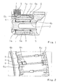
- Fig. 1 shows a section of an automatic transmission of a motor vehicle, wherein parts of a planetary stage, namely a sun gear 1, a mounted on a planetary pin 2 planetary gear 3 and a ring gear 4 are shown.
- the planetary gear 3 has an external toothing 3a, which is in engagement with an external toothing 1a of the sun gear 1 and an internal toothing 4a of the ring gear 4.
- the planet pin 2 is received in a planet carrier 5.
- the ring gear 4 has a base body 4b, which is formed integrally with the internal toothing 4a, which is produced by cutting.
- the main body 4b has a substantially cylindrical outer surface 4c, on which an additional part 6, formed as a sheet metal part, is pushed.
- the sheet metal part 6 has a driving toothing (see also Fig. 2 ), in which inner disk 7 of a disk pack 8 engage a not fully illustrated switching element.
- the ring gear 4 is thus on the one hand with the planetary gear 3 and on the other hand with the inner disk 7 into engagement, so that the ring gear 4 can be braked or fixed for example.
- the sheet-metal shaped part 6 has a first fixing element 6a, which is supported on an end-face stop surface of the planetary gear 3, and a second fixing element 6b, which rests against the opposite end face of the planetary gear 3, on.
- the first fixing element 6a is prefabricated, while the second fixing element 6b is bent after the assembly of the sheet metal part 6.
- the first and the second fixing element 6a, 6b secure the shaped sheet metal part 6 in both axial directions on the ring gear 4 and the main body 4b.
- a backup of the sheet metal part 6 in the circumferential direction can be done non-positively or positively.
- Fig. 2 shows the ring gear 4 in a perspective view with a view of the sheet metal part 6, which has a driving profile 6c designed as external teeth with approximately trapezoidal cross-section.
- the first fixing element 6a is formed as an incised, pressed-in nose, which is already provided prior to assembly of the sheet metal shaped part 6.
- the sheet metal part 6 is pushed in the axial direction on the base body 4b until the nose 6a comes to a stop.
- the second fixing member 6b which is formed as a cut-in tab, bent inwardly and secures the sheet metal part 6 in the other axial direction.
- the sheet metal part 6 is thus formed as a plate carrier for the inner plates of the switching element.
- longitudinal channels 9 are formed by the driving profile 6c, via which oil can be supplied to the plate pack 8.
Landscapes
- Engineering & Computer Science (AREA)
- General Engineering & Computer Science (AREA)
- Mechanical Engineering (AREA)
- General Details Of Gearings (AREA)
- Retarders (AREA)
- Gears, Cams (AREA)
- Diaphragms For Electromechanical Transducers (AREA)
Description
- Die Erfindung betrifft ein Bauteil mit Innen- und Außenverzahnung nach dem Oberbegriff des Patentanspruches 1.
- Bauteile mit Innen- und Außenverzahnung sind beispielsweise als Hohlräder von Planetengetrieben in einem Automatgetriebe für Kraftfahrzeuge bekannt. Derartige Hohlräder weisen eine Innenverzahnung auf, in welchen Planetenräder des Planetengetriebes umlaufen. Zusätzlich weisen die bekannten Hohlräder auf ihrem Außenumfang eine Mitnahmeverzahnung auf, in welche Innenlamellen eines Schaltelementes des Automatgetriebes eingreifen. Ein derartiges Hohlrad ist in der älteren Patentanmeldung der Anmelderin mit dem Aktenzeichen 102 006 031 788 in
Fig. 1 dargestellt. Dabei ist zur Ölversorgung des Schaltelementes zwischen der Innen- und der Außenverzahnung eine in Längsrichtung oder schräg zur Längsrichtung verlaufende Ölbohrung angeordnet. Da sowohl die Außen- als auch die Innenverzahnung spangebend hergestellt werden, sind die Herstellkosten relativ hoch. - Aus der gattungsbildenden
DE 28 21 320 A1 ist ein Planetengetriebe bekannt, welches mehrere Sonnenräder, einen mit einem Gehäuse koppelbaren Planetenträger und ein mit einer Abtriebswelle fest verbundenes Hohlrad umfasst. Durch ein drittes Sonnenrad, welches mit einem dritten Planetenrad kämmt, wird erreicht, dass beim Hochschalten keine Antriebsumschaltung erforderlich ist und dass ein größerer Übersetzungsbereich möglich ist. Das Hohlrad weist hier sowohl eine Innenverzahnung als auch eine Außenverzahnung auf, die jeweils einstückig mit dem Hohlrad gefertigt sind. Durch die Außenverzahnung ist das Hohlrad mit einer entsprechenden Verzahnung der Abtriebswelle verdrehstarr verbunden. - Es ist Aufgabe der vorliegenden Erfindung, ein Bauteil der eingangs genannten Art im Hinblick auf seine Herstellungskosten zu verbessern.
- Die Aufgabe der Erfindung wird durch die Merkmale des Patentanspruches 1 gelöst. Erfindungsgemäß ist vorgesehen, dass eine der beiden Verzahnungen, insbesondere die Innenverzahnung, einstückig mit dem Grundkörper des Bauteiles und die andere Verzahnung, insbesondere die Außenverzahnung als Zusatzteil ausgebildet sind, welches mit dem Grundkörper fügbar ist. Durch die erfindungsgemäße zweitteilige Verbundbauweise wird der Vorteil erreicht, dass eine der beiden Verzahnungen, insbesondere die Außenverzahnung nicht spangebend hergestellt werden muss, sondern kostengünstiger als separates Teil produzierbar ist.
- Nach einer vorteilhaften Ausführung ist das Zusatzteil als Blechteil ausgebildet, welches durch Umformung, vorzugsweise aus einer Blechplatine herstellbar ist. Damit kann die Außenverzahnung durch ein an sich bekanntes Umformverfahren kostengünstiger hergestellt und auf den Grundkörper des Bauteiles - wie eine Manschette - aufgesteckt werden.
- In weiterer vorteilhafter Ausgestaltung ist die Außenverzahnung als Mitnahmeverzahnung für ein Lamellenpaket, insbesondere als Lamellenträger für die Innenlamellen eines Schaltelementes ausgebildet. Derartige meist trapezförmig ausgebildete Mitnahmeprofile können durch Blechumformung günstig hergestellt werden. Darüber hinaus ergeben sich durch die erfindungsgemäße zweitteilige Verbundbauweise Gewichtsvorteile. Die in Längsrichtung verlaufenden Kanäle zwischen dem Mitnahmeprofil und dem Grundkörper können als Schmierölkanäle genutzt werden.
- Bevorzugt ist das Bauteil als Hohlrad eines Planetengetriebes ausgebildet, welches über die Außen- bzw. Mitnahmeverzahnung mit einem Schaltelement eines Automatgetriebes zusammen wirkt.
- Bevorzugt weist der Grundkörper eine im Wesentlichen zylindrische Außenfläche auf, auf welche das Blechteil mit Mitnahmeprofil aufgeschoben und in axialer Richtung fixiert wird. Dazu weisen der Grundkörper mindestens eine Anschlagfläche und das Blechteil mindestens ein Fixierelement auf. Bevorzugt kann ein erstes Fixierelement bereits im Blechteil vorgefertigt sein, z. B. als eingeschnittene, nach innen gedrückte Nase, welche am Grundkörper stirnseitig zur Anlage kommt.
- Bevorzugt kann ein zweites Fixierelement im Blechteil vorgesehen sein, welches nach der Montage, d. h. nach dem Fügen des Blechteiles mit dem Grundkörper derart umgebogen wird, dass es eine axiale Fixierung des Blechteiles gegenüber dem Grundkörper bewirkt.
- In vorteilhafter Ausgestaltung können die Fixierelemente durch Stanzprägen hergestellt werden. Somit ergeben sich für das erfindungsgemäße Bauteil Kosten- und Gewichtsvorteile, da nur eine Verzahnung, vorzugsweise die Innenverzahnung spangebend und die andere Verzahnung, vorzugsweise die Außenverzahnung spanlos, d. h. durch Blechumformung herstellbar ist. Der Fügeprozess zur Verbindung des Grundkörpers mit dem Bauteil erfordert keine zusätzlichen Fixierelemente, da diese am Blechteil vorgesehen sind.
- Ein Ausführungsbeispiel der Erfindung ist in der Zeichnung dargestellt und wird im Folgenden näher beschrieben. Es zeigen
- Fig. 1
- einen Ausschnitt aus einem Automatgetriebe mit einem erfin- dungsgemäßen Hohlrad und
- Fig. 2
- eine perspektivische Darstellung des Hohlrades mit einer als Blechumformteil ausgebildeten Mitnahmeverzahnung.
-
Fig. 1 zeigt einen Ausschnitt aus einem Automatgetriebe eines Kraftfahrzeuges, wobei Teile einer Planetenstufe, nämlich einen Sonnenrad 1, ein auf einem Planetenbolzen 2 gelagertes Planetenrad 3 sowie ein Hohlrad 4 dargestellt sind. Das Planetenrad 3 weist eine Außenverzahnung 3a auf, welche mit einer Außenverzahnung 1a des Sonnenrades 1 und einer Innenverzahnung 4a des Hohlrades 4 in Eingriff steht. Der Planetenbolzen 2 ist in einem Planetenträger 5 aufgenommen. Das Hohlrad 4 weist einen Grundkörper 4b auf, welcher einstückig mit der Innenverzahnung 4a ausgebildet ist, welche spangebend hergestellt wird. Der Grundkörper 4b weist eine im Wesentliche zylindrische Außenfläche 4c auf, auf welche ein Zusatzteil 6, ausgebildet als Blechformteil, aufgeschoben ist. Das Blechformteil 6 weist eine Mitnahmeverzahnung (vgl. auchFig. 2 ) auf, in welche Innenlamellen 7 eines Lamellenpaketes 8 eines nicht vollständig dargestellten Schaltelementes eingreifen. Das Hohlrad 4 steht somit einerseits mit dem Planetenrad 3 und andererseits mit den Innenlamellen 7 in Eingriff, sodass das Hohlrad 4 beispielsweise abgebremst bzw. festgesetzt werden kann. Das Blechformteil 6 weist ein erstes Fixierelement 6a, welches sich an einer stirnseitigen Anschlagfläche des Planetenrades 3 abstützt, und eine zweites Fixierelement 6b, welches an der gegenüberliegenden Stirnseite des Planetenrades 3 anliegt, auf. Das erste Fixierelement 6a ist vorgefertigt, während das zweite Fixierelement 6b erst nach der Montage des Blechformteiles 6 umgebogen wird. Das erste und das zweite Fixierelement 6a, 6b sichern das Blechformteil 6 in beiden axialen Richtungen auf dem Hohlrad 4 bzw. dem Grundkörper 4b. Eine Sicherung des Blechformteiles 6 in Umfangsrichtung kann kraft- oder formschlüssig erfolgen. -
Fig. 2 zeigt das Hohlrad 4 in einer perspektivischen Darstellung mit Blick auf das Blechformteil 6, welches eine als Mitnahmeprofil 6c ausgebildete Außenverzahnung mit etwa trapezförmigem Querschnitt aufweist. Das erste Fixierelement 6a ist als eingeschnittene, nach innen gedrückte Nase ausgebildet, welche bereits vor der Montage des Blechformteiles 6 vorgesehen ist. Das Blechformteil 6 wird in axialer Richtung auf den Grundkörper 4b aufgeschoben, bis die Nase 6a zum Anschlag kommt. Dann wird das zweite Fixierelement 6b, welches als eingeschnittener Lappen ausgebildet ist, nach innen umgebogen und sichert das Blechformteil 6 in der anderen axialen Richtung. Das Blechformteil 6 ist somit als Lamellenträger für die Innenlamellen des Schaltelementes ausgebildet. Zwischen dem Grundkörper 4b, der eine im Wesentlichen zylindrische Umfangsfläche 4c aufweist, werden durch das Mitnahmeprofil 6c Längskanäle 9 gebildet, über welche dem Lamellenpaket 8 Öl zugeführt werden kann. -
- 1
- Sonnenrad
- 1a
- Außenverzahnung
- 2
- Planetenbolzen
- 3
- Planetenrad
- 3a
- Außenverzahnung
- 4
- Hohlrad
- 4a
- Innenverzahnung
- 4b
- Grundkörper
- 4c
- zylindrische Außenfläche
- 5
- Planetenträger
- 6
- Zusatzteil/Blechformteil
- 6a
- 1. Fixierelement/Nase
- 6b
- 2. Fixierelement/Lappen
- 6c
- Mitnahmeprofil/Außenverzahnung
- 7
- Innenlamelle
- 8
- Lamellenpaket
- 9
- Längskanäle
Claims (10)
- Hohlrad (4) einer Planetenstufe eines Planetengetriebes, wobei das Hohlrad (4) einen Grundkörper (4b) und eine Innenverzahnung (4a) aufweist, und der Grundkörper (4b) und die Innenverzahnung (4a) einstückig ausgebildet sind, dadurch gekennzeichnet, dass der Grundkörper (4b) eine im Wesentlichen zylindrische Außenfläche (4c) aufweist und ein Zusatzteil (6) auf der Außenfläche (4c) angeordnet ist, wobei das Zusatzteil (6) eine als Mitnahmeprofil (6c) ausgebildete Außenverzahnung aufweist.
- Hohlrad (4) nach Anspruch 1, dadurch gekennzeichnet, dass das Zusatzteil (6) als durch Umformung herstellbares Blechteil ausgebildet ist.
- Hohlrad (4) nach Anspruch 1 oder 2, dadurch gekennzeichnet, dass die Außenverzahnung (6c) als Mitnahmeverzahnung für ein Lamellenpaket (8) ausgebildet ist.
- Hohlrad (4) nach Anspruch 2 oder 3, dadurch gekennzeichnet, dass der Grundkörper (4b) Anschlagflächen und das Blechteil (6) Fixierelemente (6a, 6b) aufweist, durch welche das Blechteil (6) gegenüber dem Grundkörper (4b) in axialer Richtung gesichert ist.
- Hohlrad (4) nach Anspruch 4, dadurch gekennzeichnet, dass die Anschlagflächen stirnseitig angeordnet sind.
- Hohlrad (4) nach Anspruch 4 oder 5, dadurch gekennzeichnet, dass ein erstes Fixierelement (6a) am Blechteil (6) vorgefertigt ist.
- Hohlrad (4) nach Anspruch 6, dadurch gekennzeichnet, dass das erste Fixierelement (6a) durch Stanzprägen herstellbar ist.
- Hohlrad (4) nach Anspruch 6 oder 7, dadurch gekennzeichnet, dass das erste Fixierelement als durchgestellte Nase (6a) ausgebildet ist.
- Hohlrad (4) nach einem der Ansprüche 4 bis 8, dadurch gekennzeichnet, dass ein zweites Fixierelement (6b) bei oder nach der Montage des Blechteiles (6) fertigbar ist.
- Hohlrad (4) nach Anspruch 9, dadurch gekennzeichnet, dass das zweite Fixierelement (6b) durch Umbiegen von Teilbereichen des Blechteiles (6) fertigbar ist.
Applications Claiming Priority (2)
| Application Number | Priority Date | Filing Date | Title |
|---|---|---|---|
| DE102007021194A DE102007021194A1 (de) | 2007-05-05 | 2007-05-05 | Bauteil mit Innen- und Außenverzahnung |
| PCT/EP2008/054962 WO2008135396A1 (de) | 2007-05-05 | 2008-04-24 | Bauteil mit innen- und aussenverzahnung |
Publications (2)
| Publication Number | Publication Date |
|---|---|
| EP2145121A1 EP2145121A1 (de) | 2010-01-20 |
| EP2145121B1 true EP2145121B1 (de) | 2011-01-19 |
Family
ID=39627829
Family Applications (1)
| Application Number | Title | Priority Date | Filing Date |
|---|---|---|---|
| EP08749684A Active EP2145121B1 (de) | 2007-05-05 | 2008-04-24 | Bauteil mit innen- und aussenverzahnung |
Country Status (6)
| Country | Link |
|---|---|
| US (1) | US20100137096A1 (de) |
| EP (1) | EP2145121B1 (de) |
| JP (1) | JP5307123B2 (de) |
| AT (1) | ATE496234T1 (de) |
| DE (2) | DE102007021194A1 (de) |
| WO (1) | WO2008135396A1 (de) |
Families Citing this family (8)
| Publication number | Priority date | Publication date | Assignee | Title |
|---|---|---|---|---|
| DE102008000431A1 (de) | 2008-02-28 | 2009-09-03 | Zf Friedrichshafen Ag | Bauteil von Innen- und Außenverzahnung sowie Verfahren zur Herstellung des Bauteils |
| US9121456B2 (en) | 2013-03-01 | 2015-09-01 | Schaeffler Technologies AG & Co. KG | One-way clutch carrier assembly |
| DE102014209119B4 (de) | 2014-05-14 | 2017-08-24 | Schaeffler Technologies AG & Co. KG | Freilaufeinheit und Verfahren zur Herstellung einer Freilaufeinheit |
| DE102017115130B3 (de) | 2017-07-06 | 2018-10-25 | Dr. Ing. H.C. F. Porsche Aktiengesellschaft | Innenlamellenträgeranordnung für eine nasse Lamellenkupplung |
| DE102017123144B3 (de) * | 2017-10-05 | 2019-01-03 | Schaeffler Technologies AG & Co. KG | Freilaufeinheit, Verfahren zur Herstellung eines Trägers und Verfahren zur Montage einer Freilaufeinheit |
| US10982724B2 (en) * | 2018-01-16 | 2021-04-20 | Schaeffler Technologies AG & Co. KG | Clutch carrier for a transmission |
| CN112654803A (zh) * | 2018-10-22 | 2021-04-13 | 加特可株式会社 | 齿轮的支承结构 |
| US10989252B2 (en) * | 2019-03-29 | 2021-04-27 | Schaeffler Technologies AG & Co. KG | Clutch carrier assembly for a transmission |
Family Cites Families (24)
| Publication number | Priority date | Publication date | Assignee | Title |
|---|---|---|---|---|
| US2726748A (en) * | 1950-01-25 | 1955-12-13 | Chrysler Corp | Centrifugally operated drag release for hydraulic clutch |
| JPS4829945A (de) * | 1971-08-20 | 1973-04-20 | ||
| FR2208473A5 (de) * | 1972-11-24 | 1974-06-21 | Peugeot & Renault | |
| US3977272A (en) * | 1975-05-05 | 1976-08-31 | Borg-Warner Corporation | Transmission mechanism |
| GB1602413A (en) * | 1978-05-12 | 1981-11-11 | Borg Warner Ltd | Automatic transmission mechanism |
| DE2821320A1 (de) | 1978-05-16 | 1979-11-22 | Siegfried Alexander Eisenmann | Planetengetriebe, insbesondere fuer die automatisch unter last schaltbare drehmomentuebertragung |
| AU3749078A (en) * | 1978-06-27 | 1980-01-03 | Borg Warner Ltd | Rotary drive member |
| IE53249B1 (en) * | 1981-09-04 | 1988-09-14 | Anderson Cook Inc | Method for making a composite metal-plastic gear |
| JPS5967665U (ja) * | 1982-10-28 | 1984-05-08 | いすゞ自動車株式会社 | エンジンのリングギヤ |
| DE3941299A1 (de) * | 1988-12-15 | 1990-07-12 | Zahnradfabrik Friedrichshafen | Automatgetriebe fuer kraftfahrzeuge |
| JP2772749B2 (ja) * | 1993-07-06 | 1998-07-09 | 本田技研工業株式会社 | リングギヤ |
| JPH07238998A (ja) * | 1994-03-01 | 1995-09-12 | Honda Motor Co Ltd | 遊星歯車装置におけるリングギヤ支持部材の支持構造 |
| DE4421428C1 (de) * | 1994-06-18 | 1995-07-27 | Fichtel & Sachs Ag | Mit einem Elektromotor zu einer Baueinheit verbindbares Planetengetriebe |
| US5533945A (en) * | 1994-07-06 | 1996-07-09 | Chrysler Corporation | Five-speed automatic transmission |
| JP3520623B2 (ja) * | 1995-09-07 | 2004-04-19 | トヨタ自動車株式会社 | 自動変速機 |
| JP3866395B2 (ja) * | 1997-10-30 | 2007-01-10 | 本田技研工業株式会社 | 遊星歯車機構 |
| JP2004019778A (ja) * | 2002-06-14 | 2004-01-22 | Toyota Motor Corp | 車両用遊星歯車装置 |
| DE10230861A1 (de) * | 2002-07-09 | 2004-01-22 | Zf Friedrichshafen Ag | Kraftfahrzeuggetriebe |
| DE10233335A1 (de) * | 2002-07-23 | 2004-02-12 | Zf Friedrichshafen Ag | Hydrodynamischer Drehmomentwandler |
| JP2004069021A (ja) * | 2002-08-09 | 2004-03-04 | Denso Corp | 歯車装置 |
| JP3747913B2 (ja) * | 2003-02-14 | 2006-02-22 | トヨタ自動車株式会社 | 摩擦係合装置の潤滑構造 |
| DE102006031788A1 (de) * | 2006-07-10 | 2008-01-17 | Zf Friedrichshafen Ag | Schaltelementanordnung |
| DE102007018024B4 (de) * | 2006-09-28 | 2019-11-14 | Volkswagen Ag | Differenzialanordnung eines Kfz-Antriebsstrangs |
| DE102008000431A1 (de) * | 2008-02-28 | 2009-09-03 | Zf Friedrichshafen Ag | Bauteil von Innen- und Außenverzahnung sowie Verfahren zur Herstellung des Bauteils |
-
2007
- 2007-05-05 DE DE102007021194A patent/DE102007021194A1/de not_active Withdrawn
-
2008
- 2008-04-24 JP JP2010506887A patent/JP5307123B2/ja not_active Expired - Fee Related
- 2008-04-24 DE DE502008002402T patent/DE502008002402D1/de active Active
- 2008-04-24 AT AT08749684T patent/ATE496234T1/de active
- 2008-04-24 US US12/598,468 patent/US20100137096A1/en not_active Abandoned
- 2008-04-24 EP EP08749684A patent/EP2145121B1/de active Active
- 2008-04-24 WO PCT/EP2008/054962 patent/WO2008135396A1/de active Application Filing
Also Published As
| Publication number | Publication date |
|---|---|
| JP5307123B2 (ja) | 2013-10-02 |
| WO2008135396A1 (de) | 2008-11-13 |
| DE102007021194A1 (de) | 2008-11-06 |
| JP2010526264A (ja) | 2010-07-29 |
| DE502008002402D1 (de) | 2011-03-03 |
| US20100137096A1 (en) | 2010-06-03 |
| ATE496234T1 (de) | 2011-02-15 |
| EP2145121A1 (de) | 2010-01-20 |
Similar Documents
| Publication | Publication Date | Title |
|---|---|---|
| EP2145121B1 (de) | Bauteil mit innen- und aussenverzahnung | |
| EP2344785B1 (de) | Geteiltes rad | |
| EP0875689B1 (de) | Synchronisiervorrichtung | |
| WO2006066985A1 (de) | Getriebevorrichtung, insbesondere planetengetriebe mit verbessertem aufbau | |
| DE102009046080A1 (de) | Getriebe-Antriebseinheit | |
| DE102010004856B4 (de) | Verbindungsanordnung sowie Verfahren zum Herstellen einer solchen Verbindungsanordnung | |
| DE102009002920A1 (de) | Anordnung mit einem Planetenradträger und einem Bolzenträger | |
| DE102018206171A1 (de) | Planetenaufnahmevorrichtung, Getriebe, Verfahren zum Herstellen einer drehmomentübertragenden Verbindung von zwei oder mehr als zwei Bauteilen und Verfahren zum Herstellen einer Planetenaufnahmevorrichtung | |
| DE102007062363A1 (de) | Schaltgetriebe | |
| EP1037775A1 (de) | Rohrplatine für eine wischeranlage | |
| DE10122585B4 (de) | Einrichtung zur Drehmomentübertragung mit Spielausgleich | |
| EP2064457B1 (de) | Verbindung eines ersten mit einem zweiten zylindrischen bauteil und verfahren zur montage des ersten und des zweiten bauteiles | |
| DE102019118187A1 (de) | Differenzialgetriebe | |
| EP1375969B1 (de) | Verfahren zum Herstellen eines Getriebeelementes | |
| EP3768994A1 (de) | Planetengetriebe mit einzahnigem sonnenrad mit evoloidverzahnung | |
| DE102018209834A1 (de) | Planetengetriebe | |
| DE102010032658A1 (de) | Drehmomentübertragungseinrichtung | |
| DE102015204166A1 (de) | Zahnradanordnung | |
| DE102016124243A1 (de) | Getriebevorrichtung | |
| EP2238370B1 (de) | Getriebe | |
| DE102015219855A1 (de) | Hohlrad mit Innenverzahnung und Kronenverzahnung, sowie Verfahren zu dessen Herstellung und Schaltgetriebe mit solchem Hohlrad | |
| DE102019101684A1 (de) | Baugruppe für ein Planetengetriebe, umfassend ein Hohlrad und einen Flansch sowie Verfahren zur Herstellung einer solchen Baugruppe | |
| DE102021116051B4 (de) | Zahnradanordnung mit einem Sicherungsring | |
| EP2551553A1 (de) | Getriebeanordnung | |
| DE102014203830A1 (de) | Planetengetriebe mit stoffschlüssig verbundenem Planetenträger |
Legal Events
| Date | Code | Title | Description |
|---|---|---|---|
| PUAI | Public reference made under article 153(3) epc to a published international application that has entered the european phase |
Free format text: ORIGINAL CODE: 0009012 |
|
| 17P | Request for examination filed |
Effective date: 20091106 |
|
| AK | Designated contracting states |
Kind code of ref document: A1 Designated state(s): AT BE BG CH CY CZ DE DK EE ES FI FR GB GR HR HU IE IS IT LI LT LU LV MC MT NL NO PL PT RO SE SI SK TR |
|
| AX | Request for extension of the european patent |
Extension state: AL BA MK RS |
|
| DAX | Request for extension of the european patent (deleted) | ||
| GRAP | Despatch of communication of intention to grant a patent |
Free format text: ORIGINAL CODE: EPIDOSNIGR1 |
|
| GRAS | Grant fee paid |
Free format text: ORIGINAL CODE: EPIDOSNIGR3 |
|
| GRAA | (expected) grant |
Free format text: ORIGINAL CODE: 0009210 |
|
| AK | Designated contracting states |
Kind code of ref document: B1 Designated state(s): AT BE BG CH CY CZ DE DK EE ES FI FR GB GR HR HU IE IS IT LI LT LU LV MC MT NL NO PL PT RO SE SI SK TR |
|
| REG | Reference to a national code |
Ref country code: GB Ref legal event code: FG4D Free format text: NOT ENGLISH |
|
| REG | Reference to a national code |
Ref country code: CH Ref legal event code: EP |
|
| REG | Reference to a national code |
Ref country code: IE Ref legal event code: FG4D Free format text: LANGUAGE OF EP DOCUMENT: GERMAN |
|
| REF | Corresponds to: |
Ref document number: 502008002402 Country of ref document: DE Date of ref document: 20110303 Kind code of ref document: P |
|
| REG | Reference to a national code |
Ref country code: DE Ref legal event code: R096 Ref document number: 502008002402 Country of ref document: DE Effective date: 20110303 |
|
| REG | Reference to a national code |
Ref country code: NL Ref legal event code: VDEP Effective date: 20110119 |
|
| LTIE | Lt: invalidation of european patent or patent extension |
Effective date: 20110119 |
|
| PG25 | Lapsed in a contracting state [announced via postgrant information from national office to epo] |
Ref country code: IS Free format text: LAPSE BECAUSE OF FAILURE TO SUBMIT A TRANSLATION OF THE DESCRIPTION OR TO PAY THE FEE WITHIN THE PRESCRIBED TIME-LIMIT Effective date: 20110519 Ref country code: GR Free format text: LAPSE BECAUSE OF FAILURE TO SUBMIT A TRANSLATION OF THE DESCRIPTION OR TO PAY THE FEE WITHIN THE PRESCRIBED TIME-LIMIT Effective date: 20110420 Ref country code: LV Free format text: LAPSE BECAUSE OF FAILURE TO SUBMIT A TRANSLATION OF THE DESCRIPTION OR TO PAY THE FEE WITHIN THE PRESCRIBED TIME-LIMIT Effective date: 20110119 Ref country code: ES Free format text: LAPSE BECAUSE OF FAILURE TO SUBMIT A TRANSLATION OF THE DESCRIPTION OR TO PAY THE FEE WITHIN THE PRESCRIBED TIME-LIMIT Effective date: 20110430 Ref country code: SE Free format text: LAPSE BECAUSE OF FAILURE TO SUBMIT A TRANSLATION OF THE DESCRIPTION OR TO PAY THE FEE WITHIN THE PRESCRIBED TIME-LIMIT Effective date: 20110119 Ref country code: LT Free format text: LAPSE BECAUSE OF FAILURE TO SUBMIT A TRANSLATION OF THE DESCRIPTION OR TO PAY THE FEE WITHIN THE PRESCRIBED TIME-LIMIT Effective date: 20110119 Ref country code: NO Free format text: LAPSE BECAUSE OF FAILURE TO SUBMIT A TRANSLATION OF THE DESCRIPTION OR TO PAY THE FEE WITHIN THE PRESCRIBED TIME-LIMIT Effective date: 20110419 Ref country code: PT Free format text: LAPSE BECAUSE OF FAILURE TO SUBMIT A TRANSLATION OF THE DESCRIPTION OR TO PAY THE FEE WITHIN THE PRESCRIBED TIME-LIMIT Effective date: 20110519 Ref country code: HR Free format text: LAPSE BECAUSE OF FAILURE TO SUBMIT A TRANSLATION OF THE DESCRIPTION OR TO PAY THE FEE WITHIN THE PRESCRIBED TIME-LIMIT Effective date: 20110119 |
|
| REG | Reference to a national code |
Ref country code: IE Ref legal event code: FD4D |
|
| PG25 | Lapsed in a contracting state [announced via postgrant information from national office to epo] |
Ref country code: SI Free format text: LAPSE BECAUSE OF FAILURE TO SUBMIT A TRANSLATION OF THE DESCRIPTION OR TO PAY THE FEE WITHIN THE PRESCRIBED TIME-LIMIT Effective date: 20110119 Ref country code: CY Free format text: LAPSE BECAUSE OF FAILURE TO SUBMIT A TRANSLATION OF THE DESCRIPTION OR TO PAY THE FEE WITHIN THE PRESCRIBED TIME-LIMIT Effective date: 20110119 Ref country code: FI Free format text: LAPSE BECAUSE OF FAILURE TO SUBMIT A TRANSLATION OF THE DESCRIPTION OR TO PAY THE FEE WITHIN THE PRESCRIBED TIME-LIMIT Effective date: 20110119 Ref country code: PL Free format text: LAPSE BECAUSE OF FAILURE TO SUBMIT A TRANSLATION OF THE DESCRIPTION OR TO PAY THE FEE WITHIN THE PRESCRIBED TIME-LIMIT Effective date: 20110119 Ref country code: NL Free format text: LAPSE BECAUSE OF FAILURE TO SUBMIT A TRANSLATION OF THE DESCRIPTION OR TO PAY THE FEE WITHIN THE PRESCRIBED TIME-LIMIT Effective date: 20110119 Ref country code: BG Free format text: LAPSE BECAUSE OF FAILURE TO SUBMIT A TRANSLATION OF THE DESCRIPTION OR TO PAY THE FEE WITHIN THE PRESCRIBED TIME-LIMIT Effective date: 20110419 |
|
| BERE | Be: lapsed |
Owner name: ZF FRIEDRICHSHAFEN A.G. Effective date: 20110430 |
|
| PG25 | Lapsed in a contracting state [announced via postgrant information from national office to epo] |
Ref country code: IE Free format text: LAPSE BECAUSE OF FAILURE TO SUBMIT A TRANSLATION OF THE DESCRIPTION OR TO PAY THE FEE WITHIN THE PRESCRIBED TIME-LIMIT Effective date: 20110119 Ref country code: EE Free format text: LAPSE BECAUSE OF FAILURE TO SUBMIT A TRANSLATION OF THE DESCRIPTION OR TO PAY THE FEE WITHIN THE PRESCRIBED TIME-LIMIT Effective date: 20110119 Ref country code: DK Free format text: LAPSE BECAUSE OF FAILURE TO SUBMIT A TRANSLATION OF THE DESCRIPTION OR TO PAY THE FEE WITHIN THE PRESCRIBED TIME-LIMIT Effective date: 20110119 |
|
| PLBE | No opposition filed within time limit |
Free format text: ORIGINAL CODE: 0009261 |
|
| STAA | Information on the status of an ep patent application or granted ep patent |
Free format text: STATUS: NO OPPOSITION FILED WITHIN TIME LIMIT |
|
| PG25 | Lapsed in a contracting state [announced via postgrant information from national office to epo] |
Ref country code: CZ Free format text: LAPSE BECAUSE OF FAILURE TO SUBMIT A TRANSLATION OF THE DESCRIPTION OR TO PAY THE FEE WITHIN THE PRESCRIBED TIME-LIMIT Effective date: 20110119 Ref country code: RO Free format text: LAPSE BECAUSE OF FAILURE TO SUBMIT A TRANSLATION OF THE DESCRIPTION OR TO PAY THE FEE WITHIN THE PRESCRIBED TIME-LIMIT Effective date: 20110119 Ref country code: SK Free format text: LAPSE BECAUSE OF FAILURE TO SUBMIT A TRANSLATION OF THE DESCRIPTION OR TO PAY THE FEE WITHIN THE PRESCRIBED TIME-LIMIT Effective date: 20110119 Ref country code: MC Free format text: LAPSE BECAUSE OF NON-PAYMENT OF DUE FEES Effective date: 20110430 |
|
| 26N | No opposition filed |
Effective date: 20111020 |
|
| PG25 | Lapsed in a contracting state [announced via postgrant information from national office to epo] |
Ref country code: MT Free format text: LAPSE BECAUSE OF FAILURE TO SUBMIT A TRANSLATION OF THE DESCRIPTION OR TO PAY THE FEE WITHIN THE PRESCRIBED TIME-LIMIT Effective date: 20110119 Ref country code: IT Free format text: LAPSE BECAUSE OF FAILURE TO SUBMIT A TRANSLATION OF THE DESCRIPTION OR TO PAY THE FEE WITHIN THE PRESCRIBED TIME-LIMIT Effective date: 20110119 |
|
| REG | Reference to a national code |
Ref country code: FR Ref legal event code: ST Effective date: 20111230 |
|
| PG25 | Lapsed in a contracting state [announced via postgrant information from national office to epo] |
Ref country code: FR Free format text: LAPSE BECAUSE OF NON-PAYMENT OF DUE FEES Effective date: 20110502 Ref country code: BE Free format text: LAPSE BECAUSE OF NON-PAYMENT OF DUE FEES Effective date: 20110430 |
|
| REG | Reference to a national code |
Ref country code: DE Ref legal event code: R097 Ref document number: 502008002402 Country of ref document: DE Effective date: 20111020 |
|
| REG | Reference to a national code |
Ref country code: CH Ref legal event code: PL |
|
| GBPC | Gb: european patent ceased through non-payment of renewal fee |
Effective date: 20120424 |
|
| PG25 | Lapsed in a contracting state [announced via postgrant information from national office to epo] |
Ref country code: LI Free format text: LAPSE BECAUSE OF NON-PAYMENT OF DUE FEES Effective date: 20120430 Ref country code: GB Free format text: LAPSE BECAUSE OF NON-PAYMENT OF DUE FEES Effective date: 20120424 Ref country code: CH Free format text: LAPSE BECAUSE OF NON-PAYMENT OF DUE FEES Effective date: 20120430 |
|
| PG25 | Lapsed in a contracting state [announced via postgrant information from national office to epo] |
Ref country code: LU Free format text: LAPSE BECAUSE OF NON-PAYMENT OF DUE FEES Effective date: 20110424 |
|
| PG25 | Lapsed in a contracting state [announced via postgrant information from national office to epo] |
Ref country code: TR Free format text: LAPSE BECAUSE OF FAILURE TO SUBMIT A TRANSLATION OF THE DESCRIPTION OR TO PAY THE FEE WITHIN THE PRESCRIBED TIME-LIMIT Effective date: 20110119 |
|
| PG25 | Lapsed in a contracting state [announced via postgrant information from national office to epo] |
Ref country code: HU Free format text: LAPSE BECAUSE OF FAILURE TO SUBMIT A TRANSLATION OF THE DESCRIPTION OR TO PAY THE FEE WITHIN THE PRESCRIBED TIME-LIMIT Effective date: 20110119 |
|
| REG | Reference to a national code |
Ref country code: AT Ref legal event code: MM01 Ref document number: 496234 Country of ref document: AT Kind code of ref document: T Effective date: 20130424 |
|
| PG25 | Lapsed in a contracting state [announced via postgrant information from national office to epo] |
Ref country code: AT Free format text: LAPSE BECAUSE OF NON-PAYMENT OF DUE FEES Effective date: 20130424 |
|
| P01 | Opt-out of the competence of the unified patent court (upc) registered |
Effective date: 20230528 |
|
| PGFP | Annual fee paid to national office [announced via postgrant information from national office to epo] |
Ref country code: DE Payment date: 20240306 Year of fee payment: 17 |