EP1950128A1 - Motorrad - Google Patents
Motorrad Download PDFInfo
- Publication number
- EP1950128A1 EP1950128A1 EP07024101A EP07024101A EP1950128A1 EP 1950128 A1 EP1950128 A1 EP 1950128A1 EP 07024101 A EP07024101 A EP 07024101A EP 07024101 A EP07024101 A EP 07024101A EP 1950128 A1 EP1950128 A1 EP 1950128A1
- Authority
- EP
- European Patent Office
- Prior art keywords
- steering head
- head tube
- vehicle battery
- frame
- motorcycle
- Prior art date
- Legal status (The legal status is an assumption and is not a legal conclusion. Google has not performed a legal analysis and makes no representation as to the accuracy of the status listed.)
- Granted
Links
Images
Classifications
-
- B—PERFORMING OPERATIONS; TRANSPORTING
- B62—LAND VEHICLES FOR TRAVELLING OTHERWISE THAN ON RAILS
- B62K—CYCLES; CYCLE FRAMES; CYCLE STEERING DEVICES; RIDER-OPERATED TERMINAL CONTROLS SPECIALLY ADAPTED FOR CYCLES; CYCLE AXLE SUSPENSIONS; CYCLE SIDECARS, FORECARS, OR THE LIKE
- B62K11/00—Motorcycles, engine-assisted cycles or motor scooters with one or two wheels
- B62K11/02—Frames
Definitions
- the present invention relates to a motorcycle according to the preamble of claim 1.
- the object of the invention is to provide a motorcycle in which the vehicle battery is arranged at a favorable position with regard to the weight distribution on the front and rear wheels.
- the starting point of the invention is a motorcycle, with a frame having a "steering head tube".
- a front fork or a front carrier can be mounted directly or indirectly.
- the designated as "steering head tube” frame section does not necessarily need to be provided for mounting a front fork or a front wheel.
- the steering head tube is a preferably tubular frame portion extending obliquely forwardly downwardly when viewed from above while the motorcycle is upright and located in an area located behind the handlebar of the motorcycle as viewed in the direction of travel.
- the vehicle battery is located in the immediate vicinity of the steering head tube.
- the vehicle battery is preferably arranged directly behind the steering head tube, with the rear side pointing towards the vehicle rear side of the steering head tube.
- the arrangement of the vehicle battery in this area is associated with low installation costs: The battery terminals are more accessible than in many conventional battery arrangements. Another advantage is the fact that the area in the immediate vicinity of the steering head tube is relatively well protected against contamination.
- the frame has at least one upper and at least one lower frame tube, whose front ends are connected to the steering head tube.
- the vehicle battery may be arranged in the region between the at least one upper and the at least one lower frame tube.
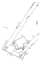
- FIG. 1 shows the basic principle of the invention.
- FIG. 1 shows a motorcycle frame 1 having a steering head tube 2.
- the motorcycle frame 1 further comprises an upper frame tube 3 and a lower frame tube 4. Front ends 5, 6 of the two frame tubes 3, 4 are connected to the steering head tube 2, z. B. welded, soldered or otherwise permanently connected firmly.
- a vehicle battery 7 is arranged in the area between the two frame tubes 3, 4 and behind the steering head tube 2.
- the vehicle battery 7 is fastened by means of a carrier plate 8.
- the support plate 8 is designed bow-shaped. Left and right arms of the ironing plate 8 are connected to frame plates, wherein in the side view shown here only a frame plate 9 can be seen, which is welded to the lower frame tube and the steering head tube 2, soldered or permanently connected in any other way.
- the steering head tube has an indentation 10, in which a front end of the vehicle battery 7 protrudes, which has the advantage that the center of gravity of the vehicle battery is very far forward with respect to the motorcycle frame, which is the wheel load distribution of the motorcycle favorably influenced.
Landscapes
- Engineering & Computer Science (AREA)
- Mechanical Engineering (AREA)
- Automatic Cycles, And Cycles In General (AREA)
Abstract
Description
- Die vorliegende Erfindung betrifft ein Motorrad gemäß dem Oberbegriff des Patentanspruches 1.
- Aufgabe der Erfindung ist es, ein Motorrad zu schaffen, bei dem die Fahrzeugbatterie an einer hinsichtlich der Gewichtsverteilung auf Vorder- und Hinterrad günstigen Position angeordnet ist.
- Diese Aufgabe wird durch die Merkmale des Patentanspruches 1 gelöst. Vorteilhafte Ausgestaltungen und Weiterbildungen der Erfindung sind den Unteransprüchen zu entnehmen.
- Ausgangspunkt der Erfindung ist ein Motorrad, mit einem Rahmen, der ein "Lenkkopfrohr" aufweist. An dem Lenkkopfrohr kann eine Vorderradgabel bzw. ein Vorderradträger unmittelbar oder mittelbar gelagert sein. Das als "Lenkkopfrohr" bezeichnete Rahmenteilstück braucht aber nicht unbedingt zur Lagerung einer Vorderradgabel oder eines Vorderradträgers vorgesehen sein. Ganz allgemein handelt es sich bei dem Lenkkopfrohr um einen vorzugsweise rohrförmigen Rahmenabschnitt, der sich bei aufrecht stehendem Motorrad von oben gesehen schräg nach vorne unten erstreckt und sich in einem Bereich befindet, der, in Fahrtrichtung gesehen, hinterhalb des Lenkers des Motorrads angeordnet ist.
- Der Kern der Erfindung besteht darin, dass die Fahrzeugbatterie, in unmittelbarer Nähe des Lenkkopfrohrs angeordnet ist. In Fahrtrichtung gesehen ist die Fahrzeugbatterie vorzugsweise unmittelbar hinterhalb des Lenkkopfrohrs angeordnet, wobei hinterhalb auf der dem Fahrzeugheck zugewandten Seite des Lenkkopfrohrs bedeutet.
- Eine in diesem Bereich, d h. relativ weit vorne und relativ weit oben, in der Nähe des Lenkers angeordnete Fahrzeugbatterie beeinflusst die Fahrdynamik und die Fahrstabilität des Motorrads positiv. Durch die Anordnung der Fahrzeugbatterien in diesem Bereich wird, im Vergleich zu herkömmlichen Motorrädern, das Hinterrad entlastet und das Vorderrad stärker belastet, was beim Anfahren den Vorteil hat, dass das Vorderrad nicht so weit ausfedert. Anders ausgedrückt befindet sich eine derart angeordnete Fahrzeugbatterie genau oder nahezu genau auf der Achse des idealen Anfahrnickausgleichs. Insbesondere wird dadurch beim starken Beschleunigen des Motorrads die Neigung zum Überschlagen nach hinten verringert und die Beschleunigungstraktion optimiert.
- Die Anordnung der Fahrzeugbatterie in diesem Bereich ist mit geringem Montageaufwand verbunden: Die Batteriepole sind besser zugänglich als bei vielen herkömmlichen Batterieanordnungen. Ein weiterer Vorteil ist darin zu sehen, dass der Bereich in unmittelbarer Nähe des Lenkkopfrohrs relativ gut vor Verschmutzung geschützt ist.
- Nach einer Weiterbildung der Erfindung weist der Rahmen mindestens ein oberes und mindestens ein unteres Rahmenrohr auf, deren vordere Enden mit dem Lenkkopfrohr verbunden sind. Die Fahrzeugbatterie kann im Bereich zwischen dem mindestens einen oberen und dem mindestens einen unteren Rahmenrohr angeordnet sein.
- Nach einer Weiterbildung der Erfindung kann im Lenkkopfrohr eine Ausnehmung, eine Einbuchtung oder ein "Ausschnitt" vorgesehen sein, in die bzw. in den die Fahrzeugbatterie hineinragt, was eine sehr Platz sparende Anordnung ermöglicht.
- Im Folgenden wird die Erfindung im Zusammenhang mit der Zeichnung näher erläutert. Die einzige
Figur 1 zeigt das Grundprinzip der Erfindung. -
Figur 1 zeigt einen Motorradrahmen 1, der ein Lenkkopfohr 2 aufweist. Der Motorradrahmen 1 weist ferner ein oberes Rahmenrohr 3 und ein unteres Rahmenrohr 4 auf. Vordere Enden 5, 6 der beiden Rahmenrohre 3, 4 sind mit dem Lenkkopfrohr 2 verbunden, z. B. verschweißt, verlötet oder in anderer Weise dauerhaft fest verbunden. Im Bereich zwischen den beiden Rahmenrohren 3, 4 und hinterhalb des Lenkkopfrohrs 2 ist eine Fahrzeugbatterie 7 angeordnet. Die Fahrzeugbatterie 7 ist mittels eines Trägerblechs 8 befestigt. Das Trägerblech 8 ist bügelförmig gestaltet. Linke bzw. rechte Arme des Bügelblechs 8 sind mit Rahmenblechen verbunden, wobei in der hier gezeigten Seitenansicht lediglich ein Rahmenblech 9 zu sehen ist, das mit dem unteren Rahmenrohr und dem Lenkkopfrohr 2 verschweißt, verlötet oder in sonstiger Weise dauerhaft verbunden ist. - Wie aus
Figur 1 ersichtlich ist, weist das Lenkkopfrohr einen Einschnitt bzw. eine Einbuchtung 10 auf, in die ein vorderes Ende der Fahrzeugbatterie 7 hineinragt, was den Vorteil hat, dass der Schwerpunkt der Fahrzeugbatterie sehr weit vorne in Bezug auf den Motorradrahmen liegt, was die Radlastverteilung des Motorrads günstig beeinflusst.
Claims (3)
- Motorrad, mit- einem Rahmen (1), der ein Lenkkopfrohr (2) aufweist, und- einer Fahrzeugbatterie (7),dadurch gekennzeichnet, dass die Fahrzeugbatterie (7) in unmittelbarer Nähe des Lenkkopfrohrs (2) angeordnet ist.
- Motorrad nach Anspruch 1, dadurch gekennzeichnet, dass der Rahmen (1) mindestens ein oberes Rahmenrohr (3) aufweist, dessen vorderes Ende (5) mit dem Lenkkopfrohr (2) verbunden ist, und mindestens ein unteres Rahmenrohr (4), dessen vorderes Ende (6) mit dem Lenkkopfrohr (2) verbunden ist und dass die Fahrzeugbatterie (7) im Bereich zwischen dem oberen und dem unteren Rahmenrohr (3, 4) angeordnet ist.
- Motorrad nach Anspruch 1 oder 2, dadurch gekennzeichnet, dass das Lenkkopfrohr (2) eine Ausnehmung bzw. Einbuchtung (10) aufweist und dass die Fahrzeugbatterie (7) in die Ausnehmung bzw. Einbuchtung (10) hineinragt.
Applications Claiming Priority (1)
| Application Number | Priority Date | Filing Date | Title |
|---|---|---|---|
| DE200710003291 DE102007003291A1 (de) | 2007-01-23 | 2007-01-23 | Motorrad |
Publications (2)
| Publication Number | Publication Date |
|---|---|
| EP1950128A1 true EP1950128A1 (de) | 2008-07-30 |
| EP1950128B1 EP1950128B1 (de) | 2009-12-02 |
Family
ID=39315030
Family Applications (1)
| Application Number | Title | Priority Date | Filing Date |
|---|---|---|---|
| EP20070024101 Not-in-force EP1950128B1 (de) | 2007-01-23 | 2007-12-12 | Motorrad |
Country Status (2)
| Country | Link |
|---|---|
| EP (1) | EP1950128B1 (de) |
| DE (2) | DE102007003291A1 (de) |
Citations (7)
| Publication number | Priority date | Publication date | Assignee | Title |
|---|---|---|---|---|
| FR2532897A1 (fr) * | 1982-09-14 | 1984-03-16 | Honda Motor Co Ltd | Motocycle |
| JPH0270587A (ja) | 1988-09-06 | 1990-03-09 | Suzuki Motor Co Ltd | 自動2輪車のヘルメット収納装置 |
| JPH03139480A (ja) * | 1989-10-25 | 1991-06-13 | Suzuki Motor Corp | 自動二輪車のフレーム |
| EP0879755A2 (de) * | 1997-05-22 | 1998-11-25 | Suzuki Motor Corporation | Batteriehalterung für Motorrad |
| JP2000038177A (ja) * | 1999-07-12 | 2000-02-08 | Suzuki Motor Corp | バッテリー付二輪車 |
| JP2002166872A (ja) | 2000-09-22 | 2002-06-11 | Honda Motor Co Ltd | 自動二輪車の電装品配置構造及び自動二輪車 |
| JP2007038727A (ja) * | 2005-08-01 | 2007-02-15 | Honda Motor Co Ltd | 自動二輪車の電装部品配置構造 |
Family Cites Families (3)
| Publication number | Priority date | Publication date | Assignee | Title |
|---|---|---|---|---|
| GB767983A (en) * | 1953-07-01 | 1957-02-13 | Nsu Werke Ag | Improvements in and relating to motor scooters |
| DE19732430A1 (de) * | 1997-07-28 | 1999-02-11 | Harald Kutze | Ein- oder mehrspuriges Muskel-Elektro-Hybrid-Fahrzeug |
| KR100964858B1 (ko) * | 2005-05-11 | 2010-06-21 | 혼다 기켄 고교 가부시키가이샤 | 모터사이클 |
-
2007
- 2007-01-23 DE DE200710003291 patent/DE102007003291A1/de not_active Withdrawn
- 2007-12-12 DE DE200750002172 patent/DE502007002172D1/de active Active
- 2007-12-12 EP EP20070024101 patent/EP1950128B1/de not_active Not-in-force
Patent Citations (7)
| Publication number | Priority date | Publication date | Assignee | Title |
|---|---|---|---|---|
| FR2532897A1 (fr) * | 1982-09-14 | 1984-03-16 | Honda Motor Co Ltd | Motocycle |
| JPH0270587A (ja) | 1988-09-06 | 1990-03-09 | Suzuki Motor Co Ltd | 自動2輪車のヘルメット収納装置 |
| JPH03139480A (ja) * | 1989-10-25 | 1991-06-13 | Suzuki Motor Corp | 自動二輪車のフレーム |
| EP0879755A2 (de) * | 1997-05-22 | 1998-11-25 | Suzuki Motor Corporation | Batteriehalterung für Motorrad |
| JP2000038177A (ja) * | 1999-07-12 | 2000-02-08 | Suzuki Motor Corp | バッテリー付二輪車 |
| JP2002166872A (ja) | 2000-09-22 | 2002-06-11 | Honda Motor Co Ltd | 自動二輪車の電装品配置構造及び自動二輪車 |
| JP2007038727A (ja) * | 2005-08-01 | 2007-02-15 | Honda Motor Co Ltd | 自動二輪車の電装部品配置構造 |
Also Published As
| Publication number | Publication date |
|---|---|
| DE102007003291A1 (de) | 2008-07-24 |
| DE502007002172D1 (de) | 2010-01-14 |
| EP1950128B1 (de) | 2009-12-02 |
Similar Documents
| Publication | Publication Date | Title |
|---|---|---|
| EP2841304B1 (de) | Zusammenklappbarer fahrradträger mit erweiterungssatz | |
| EP3024716B1 (de) | Baugruppe für ein zweirad, trike oder quad | |
| DE102008062003B4 (de) | Karosseriestruktur | |
| DE102014016455B4 (de) | Schwinge | |
| EP3118096A1 (de) | Fahrradrahmen, energieversorgungseinheit hierfür und elektrofahrrad hiermit | |
| WO2013050193A1 (de) | Rahmenelement und motor für ein fahrrad | |
| EP2726310A1 (de) | Fahrzeug mit einem als tragende strukturkomponente ausgebildeten gehäuse eines elektrischen energiespeichers | |
| DE102017212790B4 (de) | Verbindungsanordnung für seitliche Gepäckbehältnisse eines Motorrades | |
| DE102012220871B4 (de) | Vorderachsträger | |
| DE102018116195B4 (de) | Gepäckträger-Anordnung mit Adapter | |
| DE9405076U1 (de) | Gefedertes Fahrrad | |
| EP1619106B1 (de) | Universalhalter zur Befestigung von Fahrzeugteilen an einem Fahrgestellrahmen eines Lastkraftwagens | |
| WO2013072152A1 (de) | Starrachse mit luftfederung | |
| EP1950128B1 (de) | Motorrad | |
| WO2018072918A1 (de) | Scooter mit fussablagenanordnung | |
| EP1886907B1 (de) | Motorrad mit Verkleidungselement | |
| DE102017221837B4 (de) | Elastische Verbindungsanordnung für ein Motorrad | |
| EP3546327B1 (de) | Gepäckträger für ein zweirad | |
| DE102009039807A1 (de) | Frontstruktur eines Kraftfahrzeugs | |
| DE102019213902B4 (de) | Vorderrad-aufhängungseinrichtung für ein sattelfahrt-fahrzeug | |
| DE102008046593A1 (de) | Motorrad | |
| DE102006031885A1 (de) | Lastträger (Load Carrier) | |
| DE20112448U1 (de) | Fahrradrahmen | |
| DE102010055321A1 (de) | Spritzschutz für Zweiräder | |
| DE4423910C2 (de) | Befestigungsarmatur für Fahrräder |
Legal Events
| Date | Code | Title | Description |
|---|---|---|---|
| PUAI | Public reference made under article 153(3) epc to a published international application that has entered the european phase |
Free format text: ORIGINAL CODE: 0009012 |
|
| 17P | Request for examination filed |
Effective date: 20080531 |
|
| AK | Designated contracting states |
Kind code of ref document: A1 Designated state(s): AT BE BG CH CY CZ DE DK EE ES FI FR GB GR HU IE IS IT LI LT LU LV MC MT NL PL PT RO SE SI SK TR |
|
| AX | Request for extension of the european patent |
Extension state: AL BA HR MK RS |
|
| 17Q | First examination report despatched |
Effective date: 20080904 |
|
| AKX | Designation fees paid |
Designated state(s): DE FR GB IT |
|
| GRAP | Despatch of communication of intention to grant a patent |
Free format text: ORIGINAL CODE: EPIDOSNIGR1 |
|
| GRAS | Grant fee paid |
Free format text: ORIGINAL CODE: EPIDOSNIGR3 |
|
| GRAA | (expected) grant |
Free format text: ORIGINAL CODE: 0009210 |
|
| AK | Designated contracting states |
Kind code of ref document: B1 Designated state(s): DE FR GB IT |
|
| REG | Reference to a national code |
Ref country code: GB Ref legal event code: FG4D Free format text: NOT ENGLISH |
|
| REF | Corresponds to: |
Ref document number: 502007002172 Country of ref document: DE Date of ref document: 20100114 Kind code of ref document: P |
|
| PLBE | No opposition filed within time limit |
Free format text: ORIGINAL CODE: 0009261 |
|
| STAA | Information on the status of an ep patent application or granted ep patent |
Free format text: STATUS: NO OPPOSITION FILED WITHIN TIME LIMIT |
|
| 26N | No opposition filed |
Effective date: 20100903 |
|
| PG25 | Lapsed in a contracting state [announced via postgrant information from national office to epo] |
Ref country code: IT Free format text: LAPSE BECAUSE OF NON-PAYMENT OF DUE FEES Effective date: 20101212 |
|
| REG | Reference to a national code |
Ref country code: FR Ref legal event code: PLFP Year of fee payment: 9 |
|
| REG | Reference to a national code |
Ref country code: FR Ref legal event code: PLFP Year of fee payment: 10 |
|
| REG | Reference to a national code |
Ref country code: FR Ref legal event code: PLFP Year of fee payment: 11 |
|
| PGFP | Annual fee paid to national office [announced via postgrant information from national office to epo] |
Ref country code: FR Payment date: 20191219 Year of fee payment: 13 Ref country code: IT Payment date: 20191216 Year of fee payment: 13 |
|
| PGFP | Annual fee paid to national office [announced via postgrant information from national office to epo] |
Ref country code: GB Payment date: 20191220 Year of fee payment: 13 |
|
| GBPC | Gb: european patent ceased through non-payment of renewal fee |
Effective date: 20201212 |
|
| PG25 | Lapsed in a contracting state [announced via postgrant information from national office to epo] |
Ref country code: FR Free format text: LAPSE BECAUSE OF NON-PAYMENT OF DUE FEES Effective date: 20201231 Ref country code: IT Free format text: LAPSE BECAUSE OF NON-PAYMENT OF DUE FEES Effective date: 20201212 |
|
| PG25 | Lapsed in a contracting state [announced via postgrant information from national office to epo] |
Ref country code: GB Free format text: LAPSE BECAUSE OF NON-PAYMENT OF DUE FEES Effective date: 20201212 |
|
| PGFP | Annual fee paid to national office [announced via postgrant information from national office to epo] |
Ref country code: DE Payment date: 20220621 Year of fee payment: 16 |
|
| P01 | Opt-out of the competence of the unified patent court (upc) registered |
Effective date: 20230503 |
|
| REG | Reference to a national code |
Ref country code: DE Ref legal event code: R119 Ref document number: 502007002172 Country of ref document: DE |
|
| PG25 | Lapsed in a contracting state [announced via postgrant information from national office to epo] |
Ref country code: DE Free format text: LAPSE BECAUSE OF NON-PAYMENT OF DUE FEES Effective date: 20240702 |
|
| PG25 | Lapsed in a contracting state [announced via postgrant information from national office to epo] |
Ref country code: DE Free format text: LAPSE BECAUSE OF NON-PAYMENT OF DUE FEES Effective date: 20240702 |