EP1948883B1 - System zum verlegen von platten, plattenanordnung und verbindungselement zur verwendung in dem system, verfahren zum verlegen von platten und plattenfussbodenreparatursystem - Google Patents
System zum verlegen von platten, plattenanordnung und verbindungselement zur verwendung in dem system, verfahren zum verlegen von platten und plattenfussbodenreparatursystem Download PDFInfo
- Publication number
- EP1948883B1 EP1948883B1 EP06806632.3A EP06806632A EP1948883B1 EP 1948883 B1 EP1948883 B1 EP 1948883B1 EP 06806632 A EP06806632 A EP 06806632A EP 1948883 B1 EP1948883 B1 EP 1948883B1
- Authority
- EP
- European Patent Office
- Prior art keywords
- tile
- joining element
- assembly
- joining
- assemblies
- Prior art date
- Legal status (The legal status is an assumption and is not a legal conclusion. Google has not performed a legal analysis and makes no representation as to the accuracy of the status listed.)
- Active
Links
Images




Classifications
-
- E—FIXED CONSTRUCTIONS
- E04—BUILDING
- E04F—FINISHING WORK ON BUILDINGS, e.g. STAIRS, FLOORS
- E04F15/00—Flooring
- E04F15/02—Flooring or floor layers composed of a number of similar elements
- E04F15/02044—Separate elements for fastening to an underlayer
-
- E—FIXED CONSTRUCTIONS
- E04—BUILDING
- E04F—FINISHING WORK ON BUILDINGS, e.g. STAIRS, FLOORS
- E04F15/00—Flooring
- E04F15/02—Flooring or floor layers composed of a number of similar elements
- E04F15/02005—Construction of joints, e.g. dividing strips
- E04F15/02016—Construction of joints, e.g. dividing strips with sealing elements between flooring elements
-
- E—FIXED CONSTRUCTIONS
- E04—BUILDING
- E04F—FINISHING WORK ON BUILDINGS, e.g. STAIRS, FLOORS
- E04F15/00—Flooring
- E04F15/02—Flooring or floor layers composed of a number of similar elements
- E04F15/02005—Construction of joints, e.g. dividing strips
- E04F15/02022—Construction of joints, e.g. dividing strips with means for aligning the outer surfaces of the flooring elements
-
- E—FIXED CONSTRUCTIONS
- E04—BUILDING
- E04F—FINISHING WORK ON BUILDINGS, e.g. STAIRS, FLOORS
- E04F15/00—Flooring
- E04F15/02—Flooring or floor layers composed of a number of similar elements
- E04F15/02194—Flooring consisting of a number of elements carried by a non-rollable common support plate or grid
-
- E—FIXED CONSTRUCTIONS
- E04—BUILDING
- E04F—FINISHING WORK ON BUILDINGS, e.g. STAIRS, FLOORS
- E04F15/00—Flooring
- E04F15/02—Flooring or floor layers composed of a number of similar elements
- E04F15/08—Flooring or floor layers composed of a number of similar elements only of stone or stone-like material, e.g. ceramics, concrete; of glass or with a top layer of stone or stone-like material, e.g. ceramics, concrete or glass
- E04F15/082—Flooring or floor layers composed of a number of similar elements only of stone or stone-like material, e.g. ceramics, concrete; of glass or with a top layer of stone or stone-like material, e.g. ceramics, concrete or glass with a top layer of stone or stone-like material, e.g. ceramics, concrete or glass in combination with a lower layer of other material
-
- E—FIXED CONSTRUCTIONS
- E04—BUILDING
- E04F—FINISHING WORK ON BUILDINGS, e.g. STAIRS, FLOORS
- E04F15/00—Flooring
- E04F15/02—Flooring or floor layers composed of a number of similar elements
- E04F15/02044—Separate elements for fastening to an underlayer
- E04F2015/0205—Separate elements for fastening to an underlayer with load-supporting elongated furring elements between the flooring elements and the underlayer
-
- E—FIXED CONSTRUCTIONS
- E04—BUILDING
- E04F—FINISHING WORK ON BUILDINGS, e.g. STAIRS, FLOORS
- E04F15/00—Flooring
- E04F15/02—Flooring or floor layers composed of a number of similar elements
- E04F15/02044—Separate elements for fastening to an underlayer
- E04F2015/0205—Separate elements for fastening to an underlayer with load-supporting elongated furring elements between the flooring elements and the underlayer
- E04F2015/02066—Separate elements for fastening to an underlayer with load-supporting elongated furring elements between the flooring elements and the underlayer with additional fastening elements between furring elements and flooring elements
- E04F2015/02072—Separate elements for fastening to an underlayer with load-supporting elongated furring elements between the flooring elements and the underlayer with additional fastening elements between furring elements and flooring elements the additional fastening elements extending into the back side of the flooring elements
Definitions
- the invention relates to a system for setting tiles using a number of tile assemblies and joining elements interconnecting adjacent tile assemblies, each tile assembly comprising a tile member and a support member, the support member being connected to the underside of the tile member and being provided with recesses for accommodating parts of the joining elements.
- the invention further relates to a tile assembly and a joining element for use in the system.
- the invention still further relates to a method for setting tiles, and a tile floor repair method.
- a system of the type described above is known from US-A-5 323 575 .
- the support member is provided with connecting elements designed in such a way that one tile assembly comprising a tile member and a tile support can be releasable connected to an adjacent tile assembly.
- a complete tile floor can be made by interconnecting such tile assemblies.
- the construction is such that once the floor has been completed it is extremely difficult to remove a single tile assembly without damaging the tile in a non-reparable way. This is due to the fact that the connection is made by male and female elements which are alternately used on each tile assembly. Therefore it is difficult to replace a single tile or a restricted number of tiles without a substantial damage to a number of tile assemblies.
- WO 03/105654 A discloses a safety mat assembly including a plurality of safety mats having engagement profiles positioned along peripheral edges of the safety mats.
- Elongate connective members extend a length of the peripheral edges of the safety mats, and engage some of the engagement profiles of abutting safety mats.
- the connective members have an elongate first tongue and elongate second tongue, and a channel positioned between them.
- the first tongue is adapted to engage a first groove of a first safety mat
- the second tongue is adapted to engage a second groove of a second safety mat.
- One of male or female couplings are positioned at intervals along the grooves, and the other of male or female couplings are positioned at intervals along each of the first tongue and the second tongue of the connective members.
- the support member has a number of openings and/or projections extending in a direction perpendicular to a main surface of the tile member
- the joining element comprises a strip-like member provided with openings and/or projections fitting into corresponding projections and/or openings of the support members of two adjacent tile assemblies, whereby the tile assemblies are removably connected to the joining elements, and wherein the joining element is provided with an upwardly extending joint part configured to be arranged between two adjacent tile members.
- the joint part fills at least part of a gap between adjacent tile members, thereby avoiding a conventional grouting of the gap after tiling.
- tile assemblies and joining elements may be reused many times, making the system according to the present invention particularly suitable for use on fairs, exhibition grounds, flexible living and office space, etc.
- part of the tile assembly overlies part of the joining element.
- the interacting projections and/or openings are located in said parts near edges of the tile assembly and the joining element, respectively.
- the openings and/or projections of the support member are located in the recesses of the support member.
- the recesses are located under the tile member, so as to enable the joining element to be located substantially under the tile member, and thereby become at least partly, or wholly, invisible when a floor made up of the tile assemblies and joining elements is completed.
- the openings and/or projections are arranged in a row along the edges of each support member and joining element.
- Tile assemblies may be placed with full edges facing each other, or shifted relative to each other over one or more opening and/or projection pitches, if the openings and/or projections are spaced uniformly in said row.
- the projection has a substantially cylindrical shape, the projection being configured to be inserted into an opening having a substantially cylindrical shape, the opening having an inlet part with a substantially conical shape.
- the wall of the conically shaped inlet part of the opening will guide the projection into the cylindrical part of the opening, thereby moving the projection transversely relative its direction of extension, so that also the tile assembly and the joining element are moved in this direction relative to each other until the projection is in the cylindrical part of the opening.
- the projection has a tapering shape, the projection being configured to be inserted into an opening having a corresponding tapering shape.
- the wall of the tapering opening will guide the projection into the opening, thereby moving the projection transversely relative its direction of extension, so that also the tile assembly and the joining element are moved in this direction relative to each other until the projection is fully in the opening.
- the joining element may be made from an elastically deformable material, and the support element may be made from a substantially undeformable material.
- the support member is provided with the projections, and the joining element is provided with the openings.
- the joining element is configured to extend along part of the circumference of the tile assembly. Where a joining element has a plurality of edges, the joining element extends along at least one of said edges.
- the joining element is configured to extend along half the circumference of the tile assembly.
- a complete floor may be tiled with one type of tile assembly and one type of joining element resulting in a low total number of components (joining elements and tile assemblies).
- the tile member/tile assembly may be triangular, rectangular, square, or generally polygonal, such as hexagonal.
- the joining element is made from an elastically deformable material.
- Such material provides flexibility when connecting the joining element and a tile assembly, yet ensuring a proper connection.
- Such material may also be used to generate a force in a connection between projections and openings in a direction of the main surface of a tile member, by stretching the material.
- Such material further may generate a high friction against sliding of the joining element relative to an underfloor, thereby essentially fixing the tile assemblies interconnected by the joining elements against movement parallel to the main surface of the tile members relative to the underfloor.
- Such material may also provide a seal with respect to an underfloor to prevent a liquid inadvertently reaching under a tile assembly, e.g. through a crack in a tile, from spreading from under one tile assembly to under an adjacent tile assembly, provided that the joining elements being connected to said one tile assembly are in contact with each other to also provide a closed circumferential seal.
- the openings and/or projections of the tile assemblies and the joining elements are configured such that with a joining element interconnecting adjacent tile assemblies, the joining element is deformed, thereby urging the tile members of the adjacent tile assemblies towards each other. If edges of adjacent tile members contact each other, the deformation of the joining element generates tensile forces therein urging the edges of the adjacent tile members against each other. In such a way, dimensional changes of the tile members, which may e.g. be made of wood, are automatically compensated for, in that no gaps between adjacent tile members may arise.
- Tile members may be urged against each other such that essentially no liquid may pass between the tile members, thereby making the floor liquid-tight. Additionally, the tile members may be provided with an elastically deformable material on their faces contacting adjacent tile members to enhance a sealing effect against liquid.
- the joint part is made of an elastically deformable material.
- the system can be designed such that the joint part is deformed after interconnecting the tile assemblies and the joining elements.
- the joint part of the joint part may be a separate part, possibly provided with means to connect it to the joint part.
- the joint part is integral with the joining element.
- a top part of the joint part is tapered or rounded. Such an embodiment facilitates a placement of a single tile assembly in an otherwise complete floor.
- the openings and/or projections of the tile assemblies and the joining elements are configured such that with a joining element interconnecting adjacent tile assemblies, the joining element is deformed, thereby urging the tile members of the adjacent tile assemblies towards the joint part.
- the joint part possibly provided with sealing protrusions, is compressed, thereby obtaining excellent liquid-tightness properties for the tile floor.
- the joining element in particular but not exclusively a joint part thereof, is provided with a protrusion on a side configured to face a tile member, the protrusion extending along the length of the joining element.
- the protrusion may bring about a sealing effect against a liquid.
- the protrusion is compressible, for an enhancement of the sealing effect.
- the protrusion may be elastically deformable.
- the joining element is configured to have a bottom side lying essentially flush with a bottom side of the support member, thus providing an excellent support of a tile floor composed by the system of joining elements and tile assemblies. Further, in this way a high friction between the tile floor and an underfloor is reached, thereby effectively preventing the tile floor to slide relative to the underfloor.
- the tile member comprises a substantially undeformable tile, e.g. made from stone, ceramics, wood, plastic, glass, metal, or any combination thereof.
- a substantially undeformable tile may function well in combination with a deformable joint part to provide a required sealing.
- the tile at its lower edges is tapered or rounded. Such an embodiment facilitates a placement of a single tile assembly in an otherwise complete floor, e.g. while repairing a damaged or worn tile assembly/tile.
- the tile member comprises a deformable tile, such as a rubber tile or a carpet tile. Adjacent deformable tiles may be placed with their edges in contact with each other, so that joining elements, having no joint parts, are invisible when the floor is complete.
- tile members of different types may be combined, using the same joining elements, or using joining elements with joint parts on the one hand (e.g. for a floor section set with stone or ceramic tiles) and joining elements without joint parts on the other hand (e.g. for a floor section set with wooden or carpet tiles).
- the tile member may comprise a layered structure of a lower substantially undeformable tile and an upper tile, the upper tile overlying at least part of the joint part.
- each of the upper tiles may overlie half of the joint part.
- a method for setting tiles comprises: providing a number of tile assemblies; providing a number of joining elements; connecting at least one joining element to each tile assembly to provide pre-assembled tile-setting components; and interconnecting said pre-assembled tile-setting components to obtain a tile floor.
- a method for repairing a tile floor comprising a number of tile assemblies interconnected with a number of joining elements comprises: releasing the connections between a tile assembly and corresponding joining elements in the tile floor by lifting the tile assembly from the tile floor, leaving a tile assembly opening in the tile floor; and inserting a tile assembly in the tile assembly opening, thereby connecting the tile assembly to said corresponding joining elements.
- a tiling system according to the invention comprises in principle two basic members, a tile assembly 1 and a joining element 2 enabling a complete tiled floor to be made through joining a number of each of these members in an appropriate manner.
- the tile assembly 1 comprises a tile or tile member 3 and a support member 4 fixed to the bottom side of the tile.
- the tile member 3 may have any proportion and size in current use in tiling, with the size of the joining element 2 being adapted accordingly for use in combination.
- a square tile is assumed, but it is possible to use rectangular tiles or even other polygonal ones, such as e.g. triangular or hexagonal tiles.
- the tile member 3 has a customary shape and can be provided with a somewhat slant edge on the top side in order to prevent damage during tiling and during use of the resulting floor.
- the support member 4 comprises a square plate 5 which has a surface area slightly smaller than that of the bottom side of the tile member 3 and which is attached to it, e.g. by means of an adhesive.
- a raised edge 6 extends, which, when viewed in the direction of the plane of the tile member 3, has a square shape having an external dimension which is smaller than that of the plate 5, thus constituting a peripheral edge 7 which extends beyond said edge 6.
- the edge 6 is provided with openings 8 of an essentially rectangular shape between the plate 5 and a top edge 9 which juts out a little more with respect to the outer surface of the edge 6.
- the edges 6 and 7 delimit a recess of the support member 4.
- a plurality of projections 12 in the form of hollow cylinders is provided on the peripheral edge 7 and in a direction perpendicular to the surface of the plate 5 or the bottom side of the tile member 3, a plurality of projections 12 in the form of hollow cylinders is provided.
- the projections 12 are arranged in a row, and are evenly distributed over the contour of the support member 4, which means that the mutual distance between two successive projections 12 situated along the same side edge of the plate 5 is invariably the same.
- the extreme projection 12 of a support member 4 is provided in the position where an end of the edge 6 is situated.
- the whole support member 4, comprising the plate 5, edge 6, intermediate walls 10 with thickenings 11 and projections 12, may be made as an entity, but it is also possible to have it made as separate units, subsequently connected to each other in a suitable manner.
- the latter may present the advantage that for the respective members various materials may be used, each matched with the function of the member in the whole.
- the plate 5 may or may not be provided with holes in regions between the intermediate walls 10.
- the tile member 3 In use, the tile member 3 essentially rests on a ground through the edges 6 and the intermediate walls 10.
- the joining element 2 in Figures 1-4 comprises a moulding 20 in the form of an "L" such that it is capable of extending along two edges of a tile assembly 1 in connection to each other.
- the moulding 20 may also be in the form of an "I" extending along an edge of a tile assembly 1 or a part thereof.
- the moulding 20 has a "T"-shaped cross-section, which in normal use as a joining element between (two) tile assemblies 1 has the "T” positioned upside down i.e. a crossbeam 21 is under a central beam 22 (also referred to as a joint part) of the "T".
- the crossbeam 21 has a rectangular section and is provided with two recesses 23 and 24 near two angular points of the crossbeam 21, the function of which will be described hereinafter.
- the central beam 22, too has a rectangular section and on either side it is provided with a protrusion 25, 26, which extends along the whole length of the joint part, and has a section in the form of a right-angled triangle of which the oblique side is facing down in Figure 4 .
- a plurality of openings 30 is provided in the crossbeam 21, on either side of the central beam and at an even distance from each other.
- the openings 30 are of a cylindrical shape.
- Figure 4 shows only one opening 30. Near the top end (inlet part) of each cylindrical opening 30, half the wall portion 31 (the more distant one from the central beam 22) is obliquely widened in an upward direction in such a way that near the top end the opening has a virtually oval shape, i.e. near the top end, the edge of the opening is defined by two half circles interconnected by two straight (parts of) lines.
- the distance between two neighboring openings 30 on the same side of the central beam 22 is equal to the distance between two neighboring projections 12 of the support member 4.
- the joining element 2 is made of an elastic material, particularly a rubber-like material, such as natural or synthetic rubber, or a synthetic material having rubber-like characteristics, such as EPDM-rubber or the like. Just like the support member 4, the joining element 2 may be made as a whole or be composed of various units connected with each other in a suitable manner.
- a tile assembly 1 is pressed onto a joining element 2.
- the projections 12 are fed into the openings 30.
- the tile assembly 1 is pushed towards the central beam 22 of the joining element 2 as a result of the oblique wall portion 31 in the openings 30.
- the protrusion 26 is compressed, and when the tile assembly 1 with its projections 12 has been pushed fully into the openings 30, the oblique side of the trapezoidal protrusion 28 is also pushed away. Due to a suitable choice of the dimensions of the different parts of the tile assembly 1 and the joining element 2, the recess 24 is positioned behind the edge 9 of the opening 8. So, the tile member 1 and the joining element 2 are rigidly attached to each other, although they may be released from each other without undue force in case the joining element 2, in particular the crossbeam 21, is made from deformable material.
- the tile assembly 1 that has been connected to the joining element 2 to form a pre-assembled tile-setting component, and thus has been provided with two sealings along two matching edges of the tile member 3, can subsequently be put into its proper place on the previously prepared underfloor or ground. Subsequently, a second tile assembly 1 and a second joining element 2 can be connected with each other in the above manner to form a second pre-assembled tile-setting component.
- this second pre-assembled tile-setting component comprising a tile assembly 1 and a joining element 2
- this second pre-assembled tile-setting component can be connected with the first pre-assembled tile-setting component by pressing the projections 12 of the support member 4 of the second pre-assembled tile-setting component (not along an edge of the tile assembly 1 provided with a joining element 2) into openings 30 of a joining element 2 of the first pre-assembled tile-setting component, creating a fixed connection between the tile assembly of the second pre-assembled tile-setting component and the joining element 2 of the first pre-assembled tile-setting component in the same way as described above.
- the entire floor area may be covered, of course, on the understanding that the user has to make the appropriate choice as regards the orientation of the pre-assembled tile-setting components.
- the design of the joining element 2 near the far end of each leg of the L-shape is as described hereinafter.
- the crossbeam 21 of the joining element 2 does not extend farther than the edge 6 of the support member 4.
- the central beam 22 of the same joining element 2 extends as far as the edge of the tile member 3 which is parallel to the edge 6, with the protrusions 27, 28 being slightly shorter than, and being in line with the edge of the plate 5, which is slightly smaller than the tile member 3, as described above.
- An end wall of the central beam 22 is provided with a triangular protrusion 35 which has the same shape and orientation as the triangular protrusions 25, 26.
- a subsequent row of pre-assembled tile-setting components with each pre-assembled tile-setting component consisting of a tile assembly 1 and a joining element 2, is added to the pre-assembled tile-setting component already set, then a joining element 2 of these added pre-assembled tile-setting components will abut against the end of a joining element 2 of a pre-assembled tile-setting component already set.
- a corner part of a joining element 2 comes into touch with an end face of a joining element already present, so that the protrusion 35 comes to lie in opposition to a part of a protrusion 25 and thus may form a watertight connection which, in addition, is practically seamless.
- a staggered pattern of tile assemblies 1 is chosen, the same effect is obtained.
- the invention is not limited to the embodiment described and depicted, but that within the scope of the claims numerous alterations may be made without departing from the inventive idea. Accordingly, in particular it is possible to realize the shape of the projection 12 and openings 30 in a different manner. In principle, it is even feasible to design them as a through-hole and a continuous groove. Moreover, it is feasible here to apply a mechanical reversal, in which the openings have walls perpendicular to the plane of the tile assembly, while the projections have tapered walls.
- the protrusions 25, 26 such a different shape that the requirements for a watertight sealing and smooth motion of joining element and tile assembly are also fulfilled. This may be achieved, e.g. by designing the protrusions 25, 26 as triangular members in the form of an isosceles triangle which has a wide apex angle and the base of which is connected with the central beam 22.
- a joining element 2a is an elongate part which in an embodiment is in the form of an L as seen in its longitudinal direction.
- the joining element 2a has a generally T-shaped cross-section comprised of a crossbeam 21a and a central beam 22a positioned along a center line of the crossbeam 21a.
- a row of openings 30a is provided, adjacent openings 30a in a row being spaced apart at a constant pitch.
- Each opening 30a comprises a tapering, e.g. conical inlet part at its end to be facing a tile assembly.
- Each opening 30a has a cylindrical shape adapted to accommodate a projection of a tile assembly, in particular a support member thereof, in a tight manner, such as to hold the projection in the opening 30a by fiction.
- the crossbeam 21 is shorter than the lengths of the sides of a tile member, to allow the ends of a crossbeam 21 to rest against other parts of other crossbeams 21 without interference.
- the crossbeam 21a may be formed integral with the central beam 22a from a deformable, in particular elastically deformable material. However, the crossbeam 21a may also be formed as a separate part from the central beam 22a, and/or each from a different material, to be joined in a suitable manner which will not be described in detail.
- the central beam 22a when seen in cross-section, may be slightly tapering in a direction away from the crossbeam 21a. At its end facing away from the crossbeam 21a, the central beam 22a is provided with transverse protrusions 25a, 26a having a tapering free end, while adjacent to the central beam 22a and the crossbeam 21a, protrusions 27a, 28a are provided being generally L-shaped, having a tapering free end. At each end of the central beam 22a, a protrusion 35a may be provided, having a tapering free end.
- the protrusions 25a, 26a, 27a and 28a generally extend along the length of the central beam 22a.
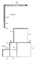
- a number of tile assemblies 1a, 1b have been connected to each other through joining elements 2a and joining elements 2b, where joining elements 2a each extend along two sides (i.e. half of the circumference) of a rectangular tile assembly 1a, and joining elements 2b each extend along two sides (i.e. half of the circumference) of a rectangular tile assembly 1b, and where the top surface areas of four tile assemblies 1b essentially equal the top surface area of one tile assembly 1a.
- the pitch, shape and size of the openings in the crossbeams of the joining elements 2a and 2b are the same, so that the joining elements 2a and 2b may be combined in constructing a floor with tile assemblies 1a, 1b, which may each have tile members made from different materials.
- each tile assembly 1a, 1b is connected to the corresponding joining element 2a, 2b, respectively, to provide pre-assembled tile-setting components. Subsequently, these pre-assembled tile-setting components are interconnected to obtain the tile floor. As can be seen in Figure 6 , it is not necessary to ensure that four corners of four adjacent tile assemblies are located at the same point; also staggered patterns of tile assemblies may be made.
- Figure 8 illustrates that in the interconnection of a tile assembly 1a and a joining element 2a (by inserting projections 12a into openings 30a), the protrusions 25a and 27a are deformed and thereby compressed to provide a liquid-tight seal between the joining element 2a and a tile member 3a at two lines along (part of) the circumference of the tile member 3a.
- the height of the central beam 22a is essentially slightly less than the height of the tile member 3a to provide the floor with a joint part which is approximately at the same level as the top surface of the tile member 3.
- a horizontally extending peripheral portion of the support member 4a of the tile assembly 1a in a mounted position rests against the top surface of the crossbeam 21a, outside the area of the protrusions 27a, 28a.
- said peripheral portion of the support member 4a it is also possible for said peripheral portion of the support member 4a to rest upon said protrusions 27a, 28a.
- a liquid-tight foil may be provided between the tile member and the support member.
- a foil is indicated with 100 in Figure 8 . Should the tile member break, enabling liquid to pass through the tile member, then the foil will prevent the liquid from passing under the tile assembly.
- the tile member may be rounded off or tapered at its lower edges, as indicated in Figure 8 by dotted lines.
- Such a design facilitates the replacement of a broken or otherwise damaged or worn tile assembly in an otherwise complete floor, by ensuring that the lower edges of the tile member easily pass into a tile assembly opening left in an otherwise complete floor after removing a tile assembly therefrom.
- FIG 9 illustrates a part of a floor made from triangular tile assemblies 1c and joining elements 2c.
- Each joining element 2c extends essentially along half of the circumference of the corresponding tile assembly 1c, i.e. along one full side of the tile assembly 1c and along half of an adjacent side of the tile assembly 1c.
- Openings in crossbeams 21c of the joining elements 2c have been omitted.
- Central beams 22c of the joining elements 2c form joints between the tile assemblies 1c.
- Protrusions may be provided similar to the protrusions 25, 25a, 26, 26a, 27, 27a, 28, 28a, 35, and 35a as shown and explained above.
- FIG 10 shows a system comprising a joining element 2d interconnecting two tile assemblies 1d.
- Each tile assembly 1d comprises a tile member 3d and a support member 4d.
- the support members 4d are provided with rows of projections 12d engaging in rows of openings of the joining element 2d.
- the joining element 2d essentially comprises only a crossbeam 21d, and does not comprise a central beam as shown in previous Figures.
- adjacent edges of the tile members 3d abut.
- the joining element 2d is provided with two protrusions 27d, 28d, which each are compressed by a tile member 3d resting on it.
- the protrusions 27d, 28d may act as seals against a liquid entering between the abutting edges of the tile members 3d from reaching the underside of the tile assemblies 1d.
- FIG 11 shows a system comprising a joining element 2e interconnecting two tile assemblies 1e.
- the joining element comprises a crossbeam 21e and a central beam 22e.
- Each tile assembly 1e comprises a tile member 3e and a support member 4e.
- the support members 4e are provided with rows of projections 12e engaging in rows of openings of the joining element 2e.
- the tile member 3e is composed of two different types of tiles: a tile 3e1 made of an essentially undeformable material, and a tile 3e2 made of an essentially undeformable material, or from a deformable material. Adjacent edges of the tiles 3e1 of the tile member 3e abut opposite sides of the central beam 22e of the joining element 2e. Adjacent edges of the tiles 3e2 of the tile member 3e abut each other.
- the joining element 2e is provided with two protrusions 27e, 28e, which each are compressed by the tile 3e1 resting on it.
- the central beam 22e and the protrusions 27e, 28e may act as seals against a liquid entering between the abutting edges of the tiles 3e2 from reaching the underside of the tile assemblies 1e.
- the bottom side of the crossbeam of the respective joining elements will act as a seal with respect to an underfloor to prevent a liquid inadvertently reaching under a tile assembly, e.g. through a crack in a tile, from spreading from under one tile assembly to under an adjacent tile assembly.
- the present invention allows to remove a single tile assembly from a floor already tiled, without it being required that for this purpose neighboring tile assemblies be removed or that the entire floor be broken up, which would result in major disadvantages or damages.
- a tile assembly can exactly be removed, and easily be replaced.
- tile floor in particular a horizontally extending tile floor or an inclined tile floor
- same or similar system may be used in constructing a (e.g. essentially vertically extending) tile wall, where the tile assemblies and/or the joining elements are attached to a wall in a suitable manner.
Landscapes
- Engineering & Computer Science (AREA)
- Architecture (AREA)
- Civil Engineering (AREA)
- Structural Engineering (AREA)
- Ceramic Engineering (AREA)
- Chemical & Material Sciences (AREA)
- Floor Finish (AREA)
- Finishing Walls (AREA)
Claims (22)
- System zum Verlegen von Platten unter Verwendung einer Anzahl von Plattenanordnungen (1; 1a, 1b; 1c; 1e) und Verbindungselementen (2; 2a, 2b; 2c; 2e), welche benachbarte Plattenanordnungen (1; 1a, 1b; 1c; 1e) verbinden, wobei jede Plattenanordnung (1; 1a, 1b; 1c; 1e) ein Plattenelement (3; 3a; 3e) und ein Tragelement (4; 4a; 4e) umfasst, wobei das Tragelement (4; 4a; 4e) mit der Unterseite des Plattenelements (3; 3a; 3e) verbunden ist und mit unter dem Plattenelement (3; 3a; 3e) angeordneten Aussparungen zum Unterbringen von Teilen der Verbindungselemente (2; 2a, 2b; 2c; 2e) versehen ist, und eine Anzahl von Öffnungen und/oder Vorsprüngen (12; 12a, 12e) aufweist, welche in den Aussparungen des Tragelements (4; 4a; 4e) angeordnet sind und sich in einer Richtung senkrecht zu einer Hauptfläche des Plattenelements (3; 3a; 3e) erstrecken, wobei das Verbindungselement (2; 2a, 2b; 2c; 2e) ein längliches streifenähnliches Element (21) umfasst, welches mit Öffnungen (30; 30a) und/oder Vorsprüngen versehen ist, welche zu entsprechenden Vorsprüngen (12; 12a, 12e) und/oder Öffnungen der Tragelemente (4; 4a; 4e) von zwei benachbarten Plattenanordnungen (1; 1a, 1b; 1c; 1e) passen, wobei die Plattenanordnungen (1; 1a, 1b; 1c; 1e) entfernbar mit den Verbindungselementen (2; 2a, 2b; 2c; 2e) verbindbar sind und wobei das Verbindungselement (2; 2a, 2b; 2c; 2e) mit einem sich aufwärts erstreckenden Fugteil (22; 22a; 22c; 22e) versehen ist, welches ausgestaltet ist, zwischen zwei benachbarten Plattenelementen (3; 3a; 3e) angeordnet zu werden.
- System nach Anspruch 1, wobei ein Teil der Plattenanordnung (1; 1a, 1b; 1c; 1e) einen Teil des Verbindungselements (2; 2a, 2b; 2c; 2e) überlagert.
- System nach einem der vorhergehenden Ansprüche, wobei die Öffnungen (30; 30a) und/oder Vorsprünge (12; 12a; 12e) in einer Reihe entlang der Ränder von jedem Tragelement (4; 4a; 4e) und Verbindungselement (2; 2a, 2b; 2c; 2e) angeordnet sind.
- System nach einem der vorhergehenden Ansprüche, wobei der Vorsprung (12; 12a; 12e) eine im Wesentlichen zylindrische Form aufweist, wobei der Vorsprung (12; 12a; 12e) ausgestaltet ist, in eine Öffnung (30; 30a) eingesetzt zu werden, welche eine im Wesentlichen zylindrische Form aufweist, wobei die Öffnung (30; 30a) einen Einlassteil mit einer im Wesentlichen konischen Form (31) aufweist.
- System nach einem der Ansprüche 1-3, wobei der Vorsprung (12; 12a; 12e) eine abgeschrägte Form aufweist, wobei der Vorsprung (12; 12a; 12e) ausgestaltet ist, in eine Öffnung (30; 30a) eingesetzt zu werden, welche eine entsprechende abgeschrägte Form aufweist.
- System nach einem der vorhergehenden Ansprüche, wobei das Tragelement (4; 4a; 4e) mit Vorsprüngen (12; 12a; 12e) versehen ist, und wobei das Verbindungselement (2; 2a, 2b; 2c; 2e) mit den Öffnungen (30; 30a) versehen ist.
- System nach einem der vorhergehenden Ansprüche, wobei das Verbindungselement (2a, 2b; 2c) ausgestaltet ist, sich entlang einem Teil des Umfangs der Plattenanordnung (1; 1a, 1b; 1c; 1e) zu erstrecken, insbesondere entlang einer Hälfte des Umfangs der Plattenanordnung (1; 1a, 1b; 1c; 1e).
- System nach einem der vorhergehenden Ansprüche, wobei das Verbindungselement (2; 2a, 2b; 2c; 2e) aus einem elastisch verformbaren Material gefertigt ist.
- System nach einem der vorhergehenden Ansprüche, wobei das Fugteil (22; 22a; 22c; 22e) aus einem elastisch verformbaren Material gefertigt ist.
- System nach einem der vorhergehenden Ansprüche, wobei das Fugteil (22; 22a; 22c; 22e) integriert mit dem Verbindungselement (2; 2a, 2b; 2c; 2e) ausgebildet ist.
- System nach einem der vorhergehenden Ansprüche, wobei ein oberer Teil des Fugteils (22; 22a; 22c; 22e) abgeschrägt oder abgerundet ist.
- System nach einem der vorhergehenden Ansprüche, wobei die Öffnungen und/oder Vorsprünge (12; 12a; 12e) der Plattenanordnungen (1; 1a, 1b; 1c; 1e) und der Verbindungselemente (2; 2a, 2b; 2c; 2e) derart ausgestaltet sind, dass mit einem Verbindungselement (2; 2a, 2b; 2c; 2e), welches benachbarte Plattenanordnungen (1; 1a, 1b; 1c; 1e) verbindet, das Verbindungselement (2; 2a, 2b; 2c; 2e) verformt wird, wodurch die Plattenelemente (3; 3a; 3e) der benachbarten Plattenanordnungen (1; 1a, 1b; 1c; 1e) in Richtung des Fugteils (22; 22a; 22c; 22e) gedrängt werden.
- System nach einem der vorhergehenden Ansprüche, wobei das Verbindungselement (2; 2a, 2b; 2c; 2e) mit einem Vorsprung (25, 26; 25a, 26a), insbesondere einem zusammendrückbaren Vorsprung, an einer Seite versehen ist, welche ausgestaltet ist, einem Plattenelement (3; 3a; 3e) gegenüber zu liegen, wobei sich der Vorsprung entlang der Länge des Verbindungselement (2; 2a, 2b; 2c; 2e) erstreckt.
- System nach einem der vorhergehenden Ansprüche, wobei das Verbindungselement (2; 2a, 2b; 2c; 2e) ausgestaltet ist, eine Unterseite aufzuweisen, welche im Wesentlichen bündig zu einer Unterseite des Tragelements (4; 4a; 4e) liegt.
- System nach einem der vorhergehenden Ansprüche, wobei das Plattenelement (3; 3a; 3e) eine im Wesentlichen unverformbare Platte umfasst, wobei die Platte aus Stein, Keramik, Holz, Kunststoff, Glas, Metall oder einer Kombination daraus gefertigt ist.
- System nach einem der vorhergehenden Ansprüche, wobei das Plattenelement (3; 3a; 3e) eine Gummiplatte oder eine Teppichplatte umfasst.
- System nach einem der vorhergehenden Ansprüche, wobei das Verbindungselement (2e) mit einem sich aufwärts erstreckenden Fugteil (22e) versehen ist, welches ausgestaltet ist, zwischen zwei benachbarten Plattenelemente (3e) angeordnet zu werden, wobei das Plattenelement (3e) eine geschichtete Struktur aus einer unteren unverformbaren Platte (3e1) und einer oberen Platte (3e2) umfasst, wobei die obere Platte (3e2) das Fugteil (22e) zumindest teilweise überlagert.
- System nach einem der vorhergehenden Ansprüche, wobei zwischen dem Plattenelement (3a) und dem Tragelement (4a) ein flüssigkeitsdichtes Material, insbesondere eine Folie (100), vorgesehen ist.
- Plattenanordnung (1; 1a, 1b; 1c; 1e) zur Verwendung in dem System nach einem der vorhergehenden Ansprüche, wobei die Plattenanordnung (1; 1a, 1b; 1c; 1e) ein Plattenelement (3; 3a; 3e) und eine Tragelement (4; 4a; 4e) umfasst, wobei das Tragelement (4; 4a; 4e) mit der Unterseite des Plattenelements (3; 3a, 3e) verbunden ist und mit unter dem Plattenelement (3; 3a; 3e) angeordneten Aussparungen versehen ist, welche zum Unterbringen eines Teils eines Verbindungselements (2; 2a, 2b; 2c; 2e) ausgestaltet sind, welches ein längliches streifenähnliches Element (21) umfasst, welches mit Öffnungen (30; 30a) und/oder Vorsprüngen versehen ist, welche zu entsprechenden Vorsprüngen (12; 12a; 12e) und/oder Öffnungen passen, welche in den Aussparungen des Tragelements (4; 4a; 4e) angeordnet sind, und welche sich in einer Richtung senkrecht zu einer Hauptfläche des Plattenelements (3; 3a; 3e) erstrecken, wobei eine Plattenanordnung (1; 1a, 1b; 1c; 1e) entfernbar mit einem Verbindungselement (2; 2a, 2b; 2c; 2e) verbindbar ist, und wobei die Plattenanordnung (1; 1a, 1b; 1c; 1e) ausgestaltet ist, einen sich aufwärts erstreckenden Fugteil (22; 22a; 22c; 22e) eines Verbindungselements (2; 2a, 2b; 2c; 2e) aufzuweisen, welches zwischen den Plattenelementen (3; 3a; 3e) von zwei benachbarten Plattenanordnungen (1; 1a, 1b; 1c; 1e) angeordnet ist.
- Verbindungselement (2; 2a, 2b; 2c; 2e) zur Verwendung in dem System nach einem der Ansprüche 1-18, wobei das Verbindungselement (2; 2a, 2b; 2c; 2e) ein längliches streifenähnliches Element (21) umfasst, welches mit Öffnungen (30; 30a) und/oder Vorsprüngen versehen ist, wobei das Verbindungselement (2; 2a, 2b; 2c; 2e) zum Verbinden benachbarter Plattenanordnungen (1; 1a, 1b; 1c; 1e) ausgestaltet ist, wobei jede Plattenanordnung (1; 1a, 1b; 1c; 1e) ein Plattenelement (3; 3a; 3e) und ein Tragelement (4; 4a; 4e) umfasst, wobei das Tragelement (4; 4a; 4e) mit der Unterseite des Plattenelements (3; 3a; 3e) verbunden ist und mit unter dem Plattenelement (3; 3a; 3e) angeordneten Aussparungen zum Unterbringen von Teilen der Verbindungselemente (2; 2a, 2b; 2c; 2e) versehen ist, und eine Anzahl von Öffnungen und/oder Vorsprüngen (12; 12a; 12e) aufweist, welche in den Aussparungen des Tragelements (4; 4a; 4e) angeordnet sind und sich in einer Richtung senkrecht zu einer Hauptfläche des Plattenelements (3; 3a; 3e) erstrecken, wobei die Öffnungen (30; 30a) und/oder Vorsprünge des Verbindungselements (2; 2a, 2b; 2c; 2e) in entsprechenden Vorsprünge (12; 12a; 12e) und/oder Öffnungen von Tragelementen von zwei benachbarten Plattenanordnungen (1; 1a, 1b; 1c; 1e) passen, wobei die Verbindungselemente (2; 2a, 2b; 2c; 2e) entfernbar mit den Plattenanordnungen (1; 1a, 1b; 1c; 1e) verbindbar sind, und wobei das Verbindungselement (2; 2a, 2b; 2c; 2e) mit einem sich aufwärts erstreckenden Fugteil (22; 22a; 22c; 22e) versehen ist, welcher ausgestaltet ist, zwischen den Plattenelementen (3; 3a; 3e) von zwei benachbarten Plattenanordnungen (1; 1a, 1b; 1c; 1e) angeordnet zu werden.
- Verfahren zum Verlegen von Platten, umfassend:Bereitstellen einer Anzahl von Plattenanordnungen (1; 1a, 1b; 1c; 1e) nach Anspruch 19,Bereitstellen einer Anzahl von Verbindungselementen (2; 2a, 2b; 2c; 2e) nach Anspruch 20,Verbinden von mindestens einem Verbindungselement (2; 2a, 2b; 2c; 2e) mit jeder Plattenanordnung (1; 1a, 1b; 1c; 1e), um vormontierte Plattenverlegekomponenten bereitzustellen; undVerbinden der vormontierten Plattenverlegekomponenten, um einen Plattenboden zu erhalten.
- Verfahren zum Reparieren eines Plattenbodens, welcher eine Anzahl von Plattenanordnungen (1; 1a, 1b; 1c; 1e) nach Anspruch 19 umfasst, welche mit einer Anzahl von Verbindungselementen (2; 2a, 2b; 2c; 2e) nach Anspruch 20 verbunden sind, wobei das Verfahren umfasst:Lösen der Verbindungen zwischen einer Plattenanordnung (1; 1a, 1b; 1c; 1e) und entsprechenden Verbindungselementen (2; 2a, 2b; 2c; 2e) in dem Plattenboden durch Anheben der Plattenanordnung (1; 1a, 1b; 1c; 1e) von dem Plattenboden, wobei eine Plattenanordnungsöffnung in dem Plattenboden zurück bleibt; undEinsetzen einer Plattenanordnung (1; 1a, 1b; 1c; 1e) in die Plattenanordnungsöffnung, wodurch die Plattenanordnung (1; 1a, 1b; 1c; 1e) mit den entsprechenden Verbindungselementen (2; 2a, 2b; 2c; 2e) verbunden wird.
Priority Applications (2)
| Application Number | Priority Date | Filing Date | Title |
|---|---|---|---|
| EP06806632.3A EP1948883B1 (de) | 2005-10-31 | 2006-10-31 | System zum verlegen von platten, plattenanordnung und verbindungselement zur verwendung in dem system, verfahren zum verlegen von platten und plattenfussbodenreparatursystem |
| PL06806632T PL1948883T3 (pl) | 2005-10-31 | 2006-10-31 | System do układania płytek, zespół płytkowy i element łączący do zastosowania w tym systemie, sposób układania płytek oraz sposób naprawiania podłogi wyłożonej płytkami |
Applications Claiming Priority (4)
| Application Number | Priority Date | Filing Date | Title |
|---|---|---|---|
| EP05077491 | 2005-10-31 | ||
| PCT/EP2006/005363 WO2007051500A1 (en) | 2005-10-31 | 2006-06-06 | System for setting tiles |
| EP06806632.3A EP1948883B1 (de) | 2005-10-31 | 2006-10-31 | System zum verlegen von platten, plattenanordnung und verbindungselement zur verwendung in dem system, verfahren zum verlegen von platten und plattenfussbodenreparatursystem |
| PCT/EP2006/010463 WO2007051591A1 (en) | 2005-10-31 | 2006-10-31 | System for setting tiles, tile assembly and joining element for use in the system, method for setting tiles, and tile floor repair method |
Publications (2)
| Publication Number | Publication Date |
|---|---|
| EP1948883A1 EP1948883A1 (de) | 2008-07-30 |
| EP1948883B1 true EP1948883B1 (de) | 2014-06-04 |
Family
ID=36764650
Family Applications (1)
| Application Number | Title | Priority Date | Filing Date |
|---|---|---|---|
| EP06806632.3A Active EP1948883B1 (de) | 2005-10-31 | 2006-10-31 | System zum verlegen von platten, plattenanordnung und verbindungselement zur verwendung in dem system, verfahren zum verlegen von platten und plattenfussbodenreparatursystem |
Country Status (14)
| Country | Link |
|---|---|
| US (1) | US8122670B2 (de) |
| EP (1) | EP1948883B1 (de) |
| JP (1) | JP5269601B2 (de) |
| CN (1) | CN101297090B (de) |
| AU (1) | AU2006310743B2 (de) |
| BR (1) | BRPI0619647B1 (de) |
| CA (1) | CA2625955C (de) |
| ES (1) | ES2487916T3 (de) |
| NO (1) | NO339569B1 (de) |
| PL (1) | PL1948883T3 (de) |
| PT (1) | PT1948883E (de) |
| RU (1) | RU2416702C2 (de) |
| WO (2) | WO2007051500A1 (de) |
| ZA (1) | ZA200806025B (de) |
Families Citing this family (33)
| Publication number | Priority date | Publication date | Assignee | Title |
|---|---|---|---|---|
| US8224776B1 (en) | 2000-07-26 | 2012-07-17 | Kdl Scan Designs Llc | Method and system for hosting entity-specific photo-sharing websites for entity-specific digital cameras |
| US6636259B1 (en) | 2000-07-26 | 2003-10-21 | Ipac Acquisition Subsidiary I, Llc | Automatically configuring a web-enabled digital camera to access the internet |
| US7748177B2 (en) | 2004-02-25 | 2010-07-06 | Connor Sport Court International, Inc. | Modular tile with controlled deflection |
| US8397466B2 (en) | 2004-10-06 | 2013-03-19 | Connor Sport Court International, Llc | Tile with multiple-level surface |
| US8407951B2 (en) | 2004-10-06 | 2013-04-02 | Connor Sport Court International, Llc | Modular synthetic floor tile configured for enhanced performance |
| USD656250S1 (en) | 2005-03-11 | 2012-03-20 | Connor Sport Court International, Llc | Tile with wide mouth coupling |
| WO2007051500A1 (en) | 2005-10-31 | 2007-05-10 | Handy Tiling Holding B.V. | System for setting tiles |
| US7900416B1 (en) | 2006-03-30 | 2011-03-08 | Connor Sport Court International, Inc. | Floor tile with load bearing lattice |
| US8499521B2 (en) | 2007-11-07 | 2013-08-06 | Valinge Innovation Ab | Mechanical locking of floor panels with vertical snap folding and an installation method to connect such panels |
| US8353140B2 (en) | 2007-11-07 | 2013-01-15 | Valinge Innovation Ab | Mechanical locking of floor panels with vertical snap folding |
| WO2009110776A1 (es) * | 2008-03-04 | 2009-09-11 | Leon Garza Jose | Mejoras a sistema de ensamble para pisos aislantes |
| NL2004045C2 (nl) * | 2010-01-04 | 2011-07-05 | Michel Louis Rieder | Vloersysteem. |
| US8881482B2 (en) | 2010-01-22 | 2014-11-11 | Connor Sport Court International, Llc | Modular flooring system |
| EP2525881A4 (de) | 2010-01-22 | 2015-09-09 | Connor Sport Court International Inc | Modulares unterbodensystem |
| US8505256B2 (en) | 2010-01-29 | 2013-08-13 | Connor Sport Court International, Llc | Synthetic floor tile having partially-compliant support structure |
| JP5048819B2 (ja) * | 2010-09-02 | 2012-10-17 | 有限会社オ−パーツ | 成形装置 |
| CN102535810A (zh) * | 2010-12-21 | 2012-07-04 | 优尼卡澳大利亚有限公司 | 地板覆盖系统 |
| US8806832B2 (en) | 2011-03-18 | 2014-08-19 | Inotec Global Limited | Vertical joint system and associated surface covering system |
| ITRN20110067A1 (it) * | 2011-09-19 | 2011-12-19 | Ceramica Faetano S P A | Pavimento ceramico a piastrelle. |
| US9216541B2 (en) | 2012-04-04 | 2015-12-22 | Valinge Innovation Ab | Method for producing a mechanical locking system for building panels |
| CN103835489B (zh) * | 2012-11-23 | 2016-12-07 | 浙江中源幕墙装饰工程有限公司 | 快速对角贴正方形小墙砖的装置 |
| US8756882B1 (en) | 2013-10-31 | 2014-06-24 | Le Groupe Dsd Inc. | Tile for use in a modular flooring system |
| CA2969191C (en) | 2014-12-22 | 2024-02-20 | Ceraloc Innovation Ab | Mechanical locking system for floor panels |
| CN107208426B (zh) | 2015-01-16 | 2019-07-26 | 塞拉洛克创新股份有限公司 | 用于地板镶板的机械锁定系统 |
| US9770383B1 (en) * | 2015-03-13 | 2017-09-26 | Tuf-Tite, Inc. | Arcuate tactile sidewalk tile arrangement and method of assembly |
| CN105133816B (zh) * | 2015-09-02 | 2017-10-24 | 蔡詠诗 | 一种用于地板砖的拼接装置及其安装方法 |
| CN106401128B (zh) * | 2016-11-07 | 2018-08-03 | 林清华 | 一种瓷砖干挂装置及其使用方法 |
| DE102016124988B4 (de) * | 2016-12-20 | 2023-03-23 | Alfer-Aluminium Gesellschaft Mbh | Beschlag und Verfahren für das Verlegen von Terrassendielen |
| CN107246132A (zh) * | 2017-07-13 | 2017-10-13 | 芜湖德丰汽车零部件有限公司 | 一种铺设用施工设备 |
| NL1043357B1 (en) | 2019-08-14 | 2021-02-24 | Bvba Tgls | Glueless tiling device and method |
| US10815672B1 (en) | 2019-09-27 | 2020-10-27 | Julie Dunne | Tile attachment device and system |
| US11725396B2 (en) * | 2020-06-08 | 2023-08-15 | Silca System, Llc | Tile-securing system and related methods |
| CN113684993A (zh) * | 2021-09-23 | 2021-11-23 | 北京城建七建设工程有限公司 | 一种装配式地面铺设结构及其铺设方法 |
Family Cites Families (29)
| Publication number | Priority date | Publication date | Assignee | Title |
|---|---|---|---|---|
| US841998A (en) * | 1906-02-20 | 1907-01-22 | Logan Willard Mulford | Tile flooring. |
| US2373808A (en) * | 1942-11-09 | 1945-04-17 | Emile S Guignon Jr | Combination lock strip and structural member |
| US3034611A (en) * | 1958-05-07 | 1962-05-15 | Zenzic John | Tapered locking device |
| US3553919A (en) * | 1968-01-31 | 1971-01-12 | Omholt Ray | Flooring systems |
| GB1350754A (en) * | 1970-04-21 | 1974-04-24 | British Ceramic Res Ass | Tile-fixing |
| DE2021503A1 (de) * | 1970-05-02 | 1971-11-25 | Freudenberg Carl Fa | Fussbodenplatten und Verfahren zu deren Verbinden |
| DE2105138A1 (de) * | 1971-02-04 | 1972-08-10 | Fassnacht, Karl, 7971 Arnach; Sporkenbach, Gustav-Adolf, 3000 Hannover | Vorrichtung zum Anbringen von Putz- und Blendsteinen an Mauerwerk und dgl |
| US3862874A (en) * | 1973-03-12 | 1975-01-28 | Joan M Hopper | Modular rug construction |
| LU79859A1 (de) * | 1977-06-24 | 1978-12-07 | Wisal Kunstharzbeton Gmbh | Verbundplatte aus keramischen sichtplatten,wie fliesen,spaltplatten oder dergleichen,zur verkleidung von waenden oder boeden sowie verfahren zu ihrer herstellung |
| DE4140683C2 (de) * | 1991-12-10 | 1995-01-12 | Flachglas Solartechnik Gmbh | Solarmodul in Plattenform, insbesondere zur Verwendung als Fassaden- oder Dachelement |
| SE501014C2 (sv) * | 1993-05-10 | 1994-10-17 | Tony Pervan | Fog för tunna flytande hårda golv |
| GB9700518D0 (en) | 1997-01-11 | 1997-02-26 | Milliken Denmark | Edging system |
| US5934729A (en) * | 1997-03-10 | 1999-08-10 | Ford Global Technologies, Inc. | Energy-absorbing fastener system |
| DE29704697U1 (de) | 1997-03-14 | 1998-07-16 | Gummiwerk Kraiburg Elastik GmbH, 84529 Tittmoning | Fußbodenbelag |
| US5907934A (en) * | 1997-09-22 | 1999-06-01 | Austin; John | Interfacing floor tile |
| SE514645C2 (sv) * | 1998-10-06 | 2001-03-26 | Perstorp Flooring Ab | Golvbeläggningsmaterial innefattande skivformiga golvelement avsedda att sammanfogas av separata sammanfogningsprofiler |
| US6233886B1 (en) * | 1999-03-23 | 2001-05-22 | Thermal Industries, Inc. | Floor assembly and associated method of making a floor assembly |
| SE522860C2 (sv) * | 2000-03-10 | 2004-03-09 | Pergo Europ Ab | Vertikalt förenade golvelement innefattande en kombination av olika golvelement |
| US6925764B2 (en) * | 2000-10-12 | 2005-08-09 | Josef Hrovath | Tile |
| CA2390828C (en) * | 2002-06-17 | 2012-05-15 | Katch Kan Holdings Inc. | Safety mat |
| US6862855B1 (en) * | 2003-04-16 | 2005-03-08 | Dave G. Milum | Structural assembly for decks, walkways, patios, and docks |
| US6976341B2 (en) * | 2003-04-29 | 2005-12-20 | Jiri Poliacek | Tile installation fixture |
| KR100566083B1 (ko) * | 2003-08-07 | 2006-03-30 | 주식회사 한솔홈데코 | 조립식 바닥재 |
| AT414147B (de) * | 2003-10-01 | 2006-09-15 | Lenhard Backhaus Hugo Dipl Ing | Belag aus belagsplatten |
| DE10349790A1 (de) * | 2003-10-24 | 2005-05-25 | Petec S.A. | Bauelement zur Herstellung von Boden- oder Wandverkleidungen |
| US7340865B2 (en) * | 2004-01-30 | 2008-03-11 | Selectech Inc. | Interlocking tile |
| AT500734B1 (de) * | 2004-02-27 | 2009-10-15 | Neuhofer Franz Jun | Vorrichtung zum überbrücken eines höhenunterschiedes zwischen zwei fussbodenflächen |
| US6966155B2 (en) * | 2004-03-29 | 2005-11-22 | Nevison Dale C H | Mat perimeter system |
| WO2007051500A1 (en) | 2005-10-31 | 2007-05-10 | Handy Tiling Holding B.V. | System for setting tiles |
-
2006
- 2006-06-06 WO PCT/EP2006/005363 patent/WO2007051500A1/en not_active Ceased
- 2006-10-31 AU AU2006310743A patent/AU2006310743B2/en not_active Ceased
- 2006-10-31 BR BRPI0619647-0A patent/BRPI0619647B1/pt not_active IP Right Cessation
- 2006-10-31 PT PT68066323T patent/PT1948883E/pt unknown
- 2006-10-31 ZA ZA200806025A patent/ZA200806025B/xx unknown
- 2006-10-31 RU RU2008119080/03A patent/RU2416702C2/ru active
- 2006-10-31 CN CN2006800399481A patent/CN101297090B/zh active Active
- 2006-10-31 WO PCT/EP2006/010463 patent/WO2007051591A1/en not_active Ceased
- 2006-10-31 PL PL06806632T patent/PL1948883T3/pl unknown
- 2006-10-31 US US12/091,225 patent/US8122670B2/en active Active
- 2006-10-31 JP JP2008538295A patent/JP5269601B2/ja not_active Expired - Fee Related
- 2006-10-31 ES ES06806632.3T patent/ES2487916T3/es active Active
- 2006-10-31 CA CA2625955A patent/CA2625955C/en active Active
- 2006-10-31 EP EP06806632.3A patent/EP1948883B1/de active Active
-
2008
- 2008-05-29 NO NO20082421A patent/NO339569B1/no not_active IP Right Cessation
Also Published As
| Publication number | Publication date |
|---|---|
| JP5269601B2 (ja) | 2013-08-21 |
| PT1948883E (pt) | 2014-08-27 |
| ES2487916T3 (es) | 2014-08-25 |
| WO2007051500A1 (en) | 2007-05-10 |
| CA2625955C (en) | 2012-05-29 |
| PL1948883T3 (pl) | 2014-10-31 |
| NO339569B1 (no) | 2017-01-09 |
| RU2416702C2 (ru) | 2011-04-20 |
| CN101297090B (zh) | 2011-11-30 |
| ZA200806025B (en) | 2009-11-25 |
| AU2006310743B2 (en) | 2012-03-22 |
| JP2009513853A (ja) | 2009-04-02 |
| WO2007051591A1 (en) | 2007-05-10 |
| US8122670B2 (en) | 2012-02-28 |
| HK1122085A1 (en) | 2009-05-08 |
| BRPI0619647A2 (pt) | 2011-10-04 |
| EP1948883A1 (de) | 2008-07-30 |
| BRPI0619647B1 (pt) | 2017-06-13 |
| NO20082421L (no) | 2008-07-24 |
| US20080271410A1 (en) | 2008-11-06 |
| RU2008119080A (ru) | 2009-12-10 |
| CN101297090A (zh) | 2008-10-29 |
| CA2625955A1 (en) | 2007-05-10 |
| AU2006310743A1 (en) | 2007-05-10 |
Similar Documents
| Publication | Publication Date | Title |
|---|---|---|
| EP1948883B1 (de) | System zum verlegen von platten, plattenanordnung und verbindungselement zur verwendung in dem system, verfahren zum verlegen von platten und plattenfussbodenreparatursystem | |
| RU2305164C2 (ru) | Система укладки напольных плиток | |
| US7690160B2 (en) | Modular floor tile system with transition edge | |
| US8640418B2 (en) | Surface covering system | |
| US12000154B2 (en) | Interlocking tile | |
| EP2369090A1 (de) | Modulare Fußbodensubstrat | |
| US20080209831A1 (en) | Loosely Laid Natural Stone Panel Floor | |
| EP4123103A1 (de) | Unterlagefliese und verfahren zum verlegen eines modularen flächenabdeckungssystems | |
| EP2149651A1 (de) | System zum Verlegen von Holzfußböden mit einem quadratischen oder rechteckigen Muster ohne Nägel, Schrauben oder Kleber | |
| EP3124717A1 (de) | Modularer, mittels mechanischer verriegelung verlegter boden, mechanisches verriegelungsverlegungsverfahren für ein modulares boden-kit zur mechanischen verriegelungsverlegung eines modularen bodens | |
| EP1555357A1 (de) | Bodenplatte | |
| GB2436570A (en) | Floorboard with rebated side and end edges | |
| HK1122085B (en) | System for setting tiles, tile assembly and joining element for use in the system, method for setting tiles, and tile floor repair method | |
| GB2559017A (en) | Fitting for laying decking boards | |
| CN113574235A (zh) | 用于条形件地板的接头 | |
| JPS6015864Y2 (ja) | 並設用板状体用連結具 | |
| US9783994B2 (en) | Self-aligning and self-spacing tile system | |
| KR20050049958A (ko) | 연결지지띠를 이용한 조립식 마루판 및 그 시공방법 | |
| EP3327217A1 (de) | Verbindungsprofil und fliesenanordnung zum horizontalen verlegen | |
| KR20180079944A (ko) | 철거 및 재시공이 용이한 조립식 타일 | |
| NZ595746A (en) | System for supporting modular components wherein the support has horizontal, vertical, and diagonal grooves connectable with projections on the components |
Legal Events
| Date | Code | Title | Description |
|---|---|---|---|
| PUAI | Public reference made under article 153(3) epc to a published international application that has entered the european phase |
Free format text: ORIGINAL CODE: 0009012 |
|
| 17P | Request for examination filed |
Effective date: 20080527 |
|
| AK | Designated contracting states |
Kind code of ref document: A1 Designated state(s): AT BE BG CH CY CZ DE DK EE ES FI FR GB GR HU IE IS IT LI LT LU LV MC NL PL PT RO SE SI SK TR |
|
| DAX | Request for extension of the european patent (deleted) | ||
| 17Q | First examination report despatched |
Effective date: 20130621 |
|
| GRAP | Despatch of communication of intention to grant a patent |
Free format text: ORIGINAL CODE: EPIDOSNIGR1 |
|
| INTG | Intention to grant announced |
Effective date: 20140107 |
|
| GRAS | Grant fee paid |
Free format text: ORIGINAL CODE: EPIDOSNIGR3 |
|
| GRAA | (expected) grant |
Free format text: ORIGINAL CODE: 0009210 |
|
| AK | Designated contracting states |
Kind code of ref document: B1 Designated state(s): AT BE BG CH CY CZ DE DK EE ES FI FR GB GR HU IE IS IT LI LT LU LV MC NL PL PT RO SE SI SK TR |
|
| REG | Reference to a national code |
Ref country code: GB Ref legal event code: FG4D |
|
| REG | Reference to a national code |
Ref country code: CH Ref legal event code: EP |
|
| REG | Reference to a national code |
Ref country code: AT Ref legal event code: REF Ref document number: 671205 Country of ref document: AT Kind code of ref document: T Effective date: 20140615 |
|
| REG | Reference to a national code |
Ref country code: IE Ref legal event code: FG4D |
|
| REG | Reference to a national code |
Ref country code: DE Ref legal event code: R096 Ref document number: 602006041804 Country of ref document: DE Effective date: 20140717 |
|
| REG | Reference to a national code |
Ref country code: SE Ref legal event code: TRGR |
|
| REG | Reference to a national code |
Ref country code: CH Ref legal event code: NV Representative=s name: ISLER AND PEDRAZZINI AG, CH |
|
| REG | Reference to a national code |
Ref country code: ES Ref legal event code: FG2A Ref document number: 2487916 Country of ref document: ES Kind code of ref document: T3 Effective date: 20140825 |
|
| REG | Reference to a national code |
Ref country code: PT Ref legal event code: SC4A Free format text: AVAILABILITY OF NATIONAL TRANSLATION Effective date: 20140808 |
|
| REG | Reference to a national code |
Ref country code: NL Ref legal event code: T3 |
|
| REG | Reference to a national code |
Ref country code: AT Ref legal event code: MK05 Ref document number: 671205 Country of ref document: AT Kind code of ref document: T Effective date: 20140604 |
|
| PG25 | Lapsed in a contracting state [announced via postgrant information from national office to epo] |
Ref country code: LT Free format text: LAPSE BECAUSE OF FAILURE TO SUBMIT A TRANSLATION OF THE DESCRIPTION OR TO PAY THE FEE WITHIN THE PRESCRIBED TIME-LIMIT Effective date: 20140604 Ref country code: FI Free format text: LAPSE BECAUSE OF FAILURE TO SUBMIT A TRANSLATION OF THE DESCRIPTION OR TO PAY THE FEE WITHIN THE PRESCRIBED TIME-LIMIT Effective date: 20140604 Ref country code: GR Free format text: LAPSE BECAUSE OF FAILURE TO SUBMIT A TRANSLATION OF THE DESCRIPTION OR TO PAY THE FEE WITHIN THE PRESCRIBED TIME-LIMIT Effective date: 20140905 Ref country code: CY Free format text: LAPSE BECAUSE OF FAILURE TO SUBMIT A TRANSLATION OF THE DESCRIPTION OR TO PAY THE FEE WITHIN THE PRESCRIBED TIME-LIMIT Effective date: 20140604 |
|
| REG | Reference to a national code |
Ref country code: PL Ref legal event code: T3 |
|
| REG | Reference to a national code |
Ref country code: LT Ref legal event code: MG4D |
|
| PG25 | Lapsed in a contracting state [announced via postgrant information from national office to epo] |
Ref country code: LV Free format text: LAPSE BECAUSE OF FAILURE TO SUBMIT A TRANSLATION OF THE DESCRIPTION OR TO PAY THE FEE WITHIN THE PRESCRIBED TIME-LIMIT Effective date: 20140604 Ref country code: AT Free format text: LAPSE BECAUSE OF FAILURE TO SUBMIT A TRANSLATION OF THE DESCRIPTION OR TO PAY THE FEE WITHIN THE PRESCRIBED TIME-LIMIT Effective date: 20140604 |
|
| REG | Reference to a national code |
Ref country code: HU Ref legal event code: AG4A Ref document number: E021226 Country of ref document: HU |
|
| PG25 | Lapsed in a contracting state [announced via postgrant information from national office to epo] |
Ref country code: RO Free format text: LAPSE BECAUSE OF FAILURE TO SUBMIT A TRANSLATION OF THE DESCRIPTION OR TO PAY THE FEE WITHIN THE PRESCRIBED TIME-LIMIT Effective date: 20140604 Ref country code: EE Free format text: LAPSE BECAUSE OF FAILURE TO SUBMIT A TRANSLATION OF THE DESCRIPTION OR TO PAY THE FEE WITHIN THE PRESCRIBED TIME-LIMIT Effective date: 20140604 Ref country code: CZ Free format text: LAPSE BECAUSE OF FAILURE TO SUBMIT A TRANSLATION OF THE DESCRIPTION OR TO PAY THE FEE WITHIN THE PRESCRIBED TIME-LIMIT Effective date: 20140604 Ref country code: SK Free format text: LAPSE BECAUSE OF FAILURE TO SUBMIT A TRANSLATION OF THE DESCRIPTION OR TO PAY THE FEE WITHIN THE PRESCRIBED TIME-LIMIT Effective date: 20140604 |
|
| PG25 | Lapsed in a contracting state [announced via postgrant information from national office to epo] |
Ref country code: IS Free format text: LAPSE BECAUSE OF FAILURE TO SUBMIT A TRANSLATION OF THE DESCRIPTION OR TO PAY THE FEE WITHIN THE PRESCRIBED TIME-LIMIT Effective date: 20141004 |
|
| REG | Reference to a national code |
Ref country code: DE Ref legal event code: R097 Ref document number: 602006041804 Country of ref document: DE |
|
| PLBE | No opposition filed within time limit |
Free format text: ORIGINAL CODE: 0009261 |
|
| STAA | Information on the status of an ep patent application or granted ep patent |
Free format text: STATUS: NO OPPOSITION FILED WITHIN TIME LIMIT |
|
| PG25 | Lapsed in a contracting state [announced via postgrant information from national office to epo] |
Ref country code: DK Free format text: LAPSE BECAUSE OF FAILURE TO SUBMIT A TRANSLATION OF THE DESCRIPTION OR TO PAY THE FEE WITHIN THE PRESCRIBED TIME-LIMIT Effective date: 20140604 |
|
| 26N | No opposition filed |
Effective date: 20150305 |
|
| PG25 | Lapsed in a contracting state [announced via postgrant information from national office to epo] |
Ref country code: MC Free format text: LAPSE BECAUSE OF FAILURE TO SUBMIT A TRANSLATION OF THE DESCRIPTION OR TO PAY THE FEE WITHIN THE PRESCRIBED TIME-LIMIT Effective date: 20140604 Ref country code: LU Free format text: LAPSE BECAUSE OF FAILURE TO SUBMIT A TRANSLATION OF THE DESCRIPTION OR TO PAY THE FEE WITHIN THE PRESCRIBED TIME-LIMIT Effective date: 20141031 |
|
| REG | Reference to a national code |
Ref country code: DE Ref legal event code: R097 Ref document number: 602006041804 Country of ref document: DE Effective date: 20150305 |
|
| PG25 | Lapsed in a contracting state [announced via postgrant information from national office to epo] |
Ref country code: SI Free format text: LAPSE BECAUSE OF FAILURE TO SUBMIT A TRANSLATION OF THE DESCRIPTION OR TO PAY THE FEE WITHIN THE PRESCRIBED TIME-LIMIT Effective date: 20140604 |
|
| REG | Reference to a national code |
Ref country code: FR Ref legal event code: PLFP Year of fee payment: 10 |
|
| PG25 | Lapsed in a contracting state [announced via postgrant information from national office to epo] |
Ref country code: BG Free format text: LAPSE BECAUSE OF FAILURE TO SUBMIT A TRANSLATION OF THE DESCRIPTION OR TO PAY THE FEE WITHIN THE PRESCRIBED TIME-LIMIT Effective date: 20140604 |
|
| REG | Reference to a national code |
Ref country code: FR Ref legal event code: PLFP Year of fee payment: 11 |
|
| REG | Reference to a national code |
Ref country code: FR Ref legal event code: PLFP Year of fee payment: 12 |
|
| REG | Reference to a national code |
Ref country code: FR Ref legal event code: PLFP Year of fee payment: 13 |
|
| PGFP | Annual fee paid to national office [announced via postgrant information from national office to epo] |
Ref country code: HU Payment date: 20200920 Year of fee payment: 15 Ref country code: CH Payment date: 20201021 Year of fee payment: 15 Ref country code: SE Payment date: 20201021 Year of fee payment: 15 |
|
| PGFP | Annual fee paid to national office [announced via postgrant information from national office to epo] |
Ref country code: PL Payment date: 20201027 Year of fee payment: 15 |
|
| REG | Reference to a national code |
Ref country code: CH Ref legal event code: PL |
|
| PG25 | Lapsed in a contracting state [announced via postgrant information from national office to epo] |
Ref country code: SE Free format text: LAPSE BECAUSE OF NON-PAYMENT OF DUE FEES Effective date: 20211101 Ref country code: HU Free format text: LAPSE BECAUSE OF NON-PAYMENT OF DUE FEES Effective date: 20211101 |
|
| PG25 | Lapsed in a contracting state [announced via postgrant information from national office to epo] |
Ref country code: LI Free format text: LAPSE BECAUSE OF NON-PAYMENT OF DUE FEES Effective date: 20211031 Ref country code: CH Free format text: LAPSE BECAUSE OF NON-PAYMENT OF DUE FEES Effective date: 20211031 |
|
| PG25 | Lapsed in a contracting state [announced via postgrant information from national office to epo] |
Ref country code: PL Free format text: LAPSE BECAUSE OF NON-PAYMENT OF DUE FEES Effective date: 20211031 |
|
| PGFP | Annual fee paid to national office [announced via postgrant information from national office to epo] |
Ref country code: ES Payment date: 20231117 Year of fee payment: 18 |
|
| PGFP | Annual fee paid to national office [announced via postgrant information from national office to epo] |
Ref country code: PT Payment date: 20231024 Year of fee payment: 18 Ref country code: IT Payment date: 20231031 Year of fee payment: 18 Ref country code: IE Payment date: 20231019 Year of fee payment: 18 Ref country code: FR Payment date: 20231023 Year of fee payment: 18 |
|
| PGFP | Annual fee paid to national office [announced via postgrant information from national office to epo] |
Ref country code: DE Payment date: 20241022 Year of fee payment: 19 |
|
| PGFP | Annual fee paid to national office [announced via postgrant information from national office to epo] |
Ref country code: BE Payment date: 20241022 Year of fee payment: 19 |
|
| PGFP | Annual fee paid to national office [announced via postgrant information from national office to epo] |
Ref country code: TR Payment date: 20241024 Year of fee payment: 19 |
|
| PG25 | Lapsed in a contracting state [announced via postgrant information from national office to epo] |
Ref country code: PT Free format text: LAPSE BECAUSE OF NON-PAYMENT OF DUE FEES Effective date: 20250430 |
|
| PG25 | Lapsed in a contracting state [announced via postgrant information from national office to epo] |
Ref country code: FR Free format text: LAPSE BECAUSE OF NON-PAYMENT OF DUE FEES Effective date: 20241031 |
|
| PG25 | Lapsed in a contracting state [announced via postgrant information from national office to epo] |
Ref country code: IT Free format text: LAPSE BECAUSE OF NON-PAYMENT OF DUE FEES Effective date: 20241031 |
|
| PG25 | Lapsed in a contracting state [announced via postgrant information from national office to epo] |
Ref country code: IE Free format text: LAPSE BECAUSE OF NON-PAYMENT OF DUE FEES Effective date: 20241031 |
|
| PGFP | Annual fee paid to national office [announced via postgrant information from national office to epo] |
Ref country code: NL Payment date: 20251022 Year of fee payment: 20 |
|
| REG | Reference to a national code |
Ref country code: ES Ref legal event code: FD2A Effective date: 20251205 |
|
| PGFP | Annual fee paid to national office [announced via postgrant information from national office to epo] |
Ref country code: GB Payment date: 20251024 Year of fee payment: 20 |
|
| PG25 | Lapsed in a contracting state [announced via postgrant information from national office to epo] |
Ref country code: ES Free format text: LAPSE BECAUSE OF NON-PAYMENT OF DUE FEES Effective date: 20241101 |