EP1947852A2 - Mobiles Funkendgerät mit einer montierbaren und abnehmbaren Kamera - Google Patents
Mobiles Funkendgerät mit einer montierbaren und abnehmbaren Kamera Download PDFInfo
- Publication number
- EP1947852A2 EP1947852A2 EP08008577A EP08008577A EP1947852A2 EP 1947852 A2 EP1947852 A2 EP 1947852A2 EP 08008577 A EP08008577 A EP 08008577A EP 08008577 A EP08008577 A EP 08008577A EP 1947852 A2 EP1947852 A2 EP 1947852A2
- Authority
- EP
- European Patent Office
- Prior art keywords
- destination terminal
- radio mobile
- mobile terminal
- image data
- camera
- Prior art date
- Legal status (The legal status is an assumption and is not a legal conclusion. Google has not performed a legal analysis and makes no representation as to the accuracy of the status listed.)
- Withdrawn
Links
- 230000005540 biological transmission Effects 0.000 claims description 15
- 238000001514 detection method Methods 0.000 claims description 4
- 238000010586 diagram Methods 0.000 description 7
- 230000000694 effects Effects 0.000 description 7
- 230000003247 decreasing effect Effects 0.000 description 1
- 230000008676 import Effects 0.000 description 1
- 238000000034 method Methods 0.000 description 1
- 230000010355 oscillation Effects 0.000 description 1
- 239000011800 void material Substances 0.000 description 1
Images



Classifications
-
- H—ELECTRICITY
- H04—ELECTRIC COMMUNICATION TECHNIQUE
- H04N—PICTORIAL COMMUNICATION, e.g. TELEVISION
- H04N7/00—Television systems
- H04N7/14—Systems for two-way working
- H04N7/141—Systems for two-way working between two video terminals, e.g. videophone
- H04N7/142—Constructional details of the terminal equipment, e.g. arrangements of the camera and the display
-
- H—ELECTRICITY
- H04—ELECTRIC COMMUNICATION TECHNIQUE
- H04N—PICTORIAL COMMUNICATION, e.g. TELEVISION
- H04N7/00—Television systems
- H04N7/14—Systems for two-way working
- H04N7/141—Systems for two-way working between two video terminals, e.g. videophone
- H04N7/148—Interfacing a video terminal to a particular transmission medium, e.g. ISDN
-
- H—ELECTRICITY
- H04—ELECTRIC COMMUNICATION TECHNIQUE
- H04N—PICTORIAL COMMUNICATION, e.g. TELEVISION
- H04N7/00—Television systems
- H04N7/14—Systems for two-way working
- H04N7/141—Systems for two-way working between two video terminals, e.g. videophone
- H04N7/142—Constructional details of the terminal equipment, e.g. arrangements of the camera and the display
- H04N2007/145—Handheld terminals
Definitions
- the present invention relates to a radio mobile terminal.
- Radio mobile terminals include a radio mobile videophone terminal that can send and receive motion pictures as well as voices by attaching a camera to a commercially available mobile telephone.
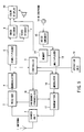
- This type of videophone terminals employs a configuration as shown in FIG. 8 for communicating data including voices and images with a remote terminal via a base station.
- a high-frequency signal received at an antenna 1 is supplied to a receiver 3 via a shared unit 2.
- the supplied signal is frequency-converted to a low-frequency signal (baseband signal) based on a local oscillation signal from a frequency synthesizer 18, and then is demodulated in a demodulator 4.
- the demodulated signal is transferred to a controller 5 that reads a control signal therefrom.
- the demodulated signal is also supplied to a demultiplexer 6.
- the multiplexed signal is separated into a voice signal and an image signal.
- a voice signal is decoded in a voice decoder 7 and is output from a speaker 8 as a voice.
- An image signal is decoded in an image decoder 9 and is displayed on an color display 10 functioning as a display unit.
- a camera 11 captures a subject to generate an image signal.
- the generated image signal is encoded in an image encoder 12, and then is supplied to a multiplexer 13.
- a voice signal entered from a microphone 14 is encoded in a voice encoder 15, and then is supplied to a multiplexer 13.
- the multiplexer 13 multiplexes encoded image and voice signals.
- a multiplexed signal is modulated in a modulator 16, and then is sent to a base station via a transmitter 17, the shared unit 2, and the antenna 1.
- the frequency synthesizer 18 generates frequencies needed for radio communication.
- An operation unit 19 is used for various key operations.
- FIG. 9 shows an outline of the above-mentioned videophone terminal. Its body is provided with the color display 10 and the operation unit 19. The upper part of the body is provided with the antenna 1 and the camera 11.
- a videophone terminal uses a relatively large camera for providing videophone capabilities.
- a videophone terminal equipped with a camera as shown in FIG. 9 has a volume of approximately 200 ml.
- Contrary to an ordinary mobile telephone there has a problem of inconvenience that such an apparatus is too large and heavy to carry say in a pocket of user's clothes during an out-of-service state of the apparatus.
- the camera's movable parts may be damaged.
- the object of the present invention is to provide a radio mobile terminal that is conveniently transportable during an out-of-service state and can be easily used as a videophone during operation.
- the first aspect of the present invention is a radio mobile terminal capable of communicating data including voices and images with a destination terminal comprising:
- the second aspect of the present invention is a radio mobile terminal capable of communicating data including voices and images with a destination terminal comprising:
- the third aspect of the present invention is a radio mobile terminal capable of communicating data including voices and images with a destination terminal comprising:
- FIG. 1 is a block diagram showing a configuration of a radio mobile videophone terminal (simply called a radio mobile terminal hereafter) according to the first embodiment of the present invention. Same components in FIGS. 1 and 8 are assigned same numbers. Different components are chiefly described here.
- a camera 11 for this embodiment can be mounted and detached via a connector 21 as a connection unit.
- a disconnection detector 20 detects whether the camera 11 is detached or mounted, and then issues a detection signal to a controller 5.
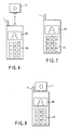
- FIG. 6 shows the camera 11 can be freely detached or mounted on the radio mobile terminal.
- the controller 5 When reading a detection signal indicating that the camera 11 is detached, the controller 5 operates assuming that the camera 11 is not mounted. When reading a detection signal indicating that the camera 11 is mounted, the controller operates assuming that the camera 11 is mounted.
- FIG. 2 is an operation flowchart for outgoing and incoming calls according to the first embodiment of the present invention.
- the controller 5 checks if there is an incoming call from a destination terminal (step S32).
- step S32 results in YES
- the controller 5 uses the received signal to determine if the call has terminated in a videophone mode (step S33).
- step S33 results in YES
- the controller checks if the camera 11 is mounted according to a signal from the disconnection detector 20 (step S34).
- step S34 results in YES, the videophone mode takes effect immediately, enabling videophone communication (step S35).
- step S34 results in NO
- control is passed to step S36 to generate an alarm and enter a wait state for a specified time.
- the controller rechecks if the camera 11 is mounted according to a signal from the disconnection detector 20 (step S37).
- step S37 results in YES
- control is passed to step 35 to enable the videophone mode.
- step S37 results in NO
- the controller enters an image reception mode (step S38) that just receives video images from the destination terminal for communication.
- step S33 results in NO
- the controller proceeds to step S41 to enter a voice mode.
- step S32 results in NO
- the controller proceeds to step 39 to check if an outgoing call is generated.
- step S39 results in NO
- control returns to step S32.
- step S39 results in YES to indicate call origination
- the controller 5 checks if the destination terminal enters the videophone mode according to a signal from a base station (step S40).
- step S40 results in YES
- the controller follows the same procedure thereafter as for the call termination depending on whether the camera 11 is mounted (step S34).
- step S40 results in NO
- control is passed to step S41 to enable the voice mode.
- this embodiment allows the camera 11 to be mounted or detached.
- the camera can be detached for improved portability when it is not needed.
- the radio mobile terminal checks if the videophone mode takes effect. When the videophone mode takes effect, it is possible to select whether to perform videophone communication with the camera 11 mounted or to just receive images from the destination depending on needs.
- a call is to be originated from the own radio mobile terminal, it is possible to first check if the destination terminal is in the videophone mode. Only when the destination terminal is in the videophone mode, videophone communication is available with the own camera 11 mounted.
- the above-mentioned first embodiment can provide a radio mobile terminal that is conveniently transported during an out-of-service state and is easily operated as a videophone when needed.
- FIG. 3 is a block diagram showing a configuration of a radio mobile terminal according to the second embodiment of the present invention.
- memory 22 as an image storage is added to FIG. 3 .
- This embodiment uses a connector 21 to import image data captured by the camera 11 during an out-of-service state.
- the imported image data is encoded in a image encoder 12 and is stored as self-portrait data in the memory 22.
- FIG. 4 is an operation flowchart for outgoing and incoming calls according to the second embodiment of the present invention. Same flowchart steps in FIGS. 2 and 4 are assigned same step numbers.
- an incoming call is confirmed at step S32 for example.
- the controller 5 checks if the camera 11 is active at next step S34. Inactive states of the camera 11 include cases where the camera 11 is not mounted or where the camera 11 is mounted but does not operate.
- step S34 results in NO
- the controller proceeds to step S42 to check if self-portrait data is stored in the memory 22.
- step S42 results in YES
- the controller transfers the encoded self-portrait data to a multiplexer 13 to enable a pseudo-videophone mode (step S43).
- Data in the memory 22 can be any character instead of a self-portrait.
- the self-portrait data which is sent to the destination terminal is the one which is stored in advance in the memory 22, rather than the realtime image (in this case, voice data is sent to the destination terminal realtime).
- step S42 results in NO, there is no image data to send, automatically causing the image reception mode (step S38).
- the controller rechecks if the camera 11 is mounted (step S37).
- step S37 results in YES, the videophone mode is enabled.
- step S37 results in NO, the voice mode is enabled.
- image data stored in the memory 22 is transmitted when the camera 11 is not mounted, or is mounted but does not operate in the videophone mode. It is possible to provide pseudo-videophone communication without transmitting a realtime image.
- This embodiment provides such an advantage that a user can set to the terminal whether the stored image data should be sent or not instead of a realtime image, prior to or during the communication.
- this embodiment includes effects of the first embodiment such as improved portability during an out-of-service state and easy operability as a videophone on demand. Since image data is stored in an encoded format, a required amount of memory can be decreased. This provides an advantage of eliminating a need to encode images at the time of videophone communication.
- the second embodiment it is possible to decrease an amount of memory required just by storing image data for a short time (say approximately 10 seconds) in the memory 22. By repeating this operation, a user can send entire data to the destination terminal.
- FIG. 5 is a block diagram showing a configuration of a radio mobile terminal according to the third embodiment of the present invention.
- the configuration in FIG. 5 is void of the image encoder 12, the disconnection detector 20, the connector 21, and the camera 11 in the configuration for the second embodiment in FIG. 3 .
- the configuration in FIG. 5 has no camera as shown in FIG. 7 .
- self-portrait data captured by say a digital camera is encoded on a personal computer.
- the encoded data is imported into the radio mobile terminal and is stored in the memory 22.
- the memory 22 it is also possible to use the memory 22 for storing image data transmitted from a networked server connected to a base station or from other radio mobile terminals. Pseudo-videophone communication with the destination terminal is available by sending image data stored in the memory 22.
- the third embodiment eliminates the camera and necessary components such as the image encoder 12, the disconnection detector 20, and the connector 21.
- the radio mobile terminal can be more compact and lightweight. Another advantage is more improved operability because a user need not mount or detach the camera.
- the voice transmission mode allows the radio mobile terminal to transmit voice data to the destination terminal.
- the voice reception mode allows the radio mobile terminal to receive voice data from the destination terminal.
- the radio mobile terminal can send to the destination terminal an image indicating that she or he is speaking.
- the radio mobile terminal can send to the destination terminal an image indicating that she or he is not speaking. This can eliminate unnaturalness during videophone communication.
Landscapes
- Engineering & Computer Science (AREA)
- Multimedia (AREA)
- Signal Processing (AREA)
- Computer Networks & Wireless Communication (AREA)
- Two-Way Televisions, Distribution Of Moving Picture Or The Like (AREA)
- Telephone Function (AREA)
- Mobile Radio Communication Systems (AREA)
Applications Claiming Priority (2)
| Application Number | Priority Date | Filing Date | Title |
|---|---|---|---|
| JP05267299A JP3308923B2 (ja) | 1999-03-01 | 1999-03-01 | 無線携帯端末 |
| EP00103476A EP1033876B1 (de) | 1999-03-01 | 2000-03-01 | Mobilfunkendgerät mit befestigbarer und entfernbarer Kamera |
Related Parent Applications (1)
| Application Number | Title | Priority Date | Filing Date |
|---|---|---|---|
| EP00103476A Division EP1033876B1 (de) | 1999-03-01 | 2000-03-01 | Mobilfunkendgerät mit befestigbarer und entfernbarer Kamera |
Publications (1)
| Publication Number | Publication Date |
|---|---|
| EP1947852A2 true EP1947852A2 (de) | 2008-07-23 |
Family
ID=12921375
Family Applications (2)
| Application Number | Title | Priority Date | Filing Date |
|---|---|---|---|
| EP08008577A Withdrawn EP1947852A2 (de) | 1999-03-01 | 2000-03-01 | Mobiles Funkendgerät mit einer montierbaren und abnehmbaren Kamera |
| EP00103476A Expired - Lifetime EP1033876B1 (de) | 1999-03-01 | 2000-03-01 | Mobilfunkendgerät mit befestigbarer und entfernbarer Kamera |
Family Applications After (1)
| Application Number | Title | Priority Date | Filing Date |
|---|---|---|---|
| EP00103476A Expired - Lifetime EP1033876B1 (de) | 1999-03-01 | 2000-03-01 | Mobilfunkendgerät mit befestigbarer und entfernbarer Kamera |
Country Status (2)
| Country | Link |
|---|---|
| EP (2) | EP1947852A2 (de) |
| JP (1) | JP3308923B2 (de) |
Cited By (1)
| Publication number | Priority date | Publication date | Assignee | Title |
|---|---|---|---|---|
| US11757706B2 (en) | 2019-07-19 | 2023-09-12 | Razberi Secure Technologies, Llc | Switch monitoring system and method of use |
Families Citing this family (13)
| Publication number | Priority date | Publication date | Assignee | Title |
|---|---|---|---|---|
| WO2000069158A1 (en) | 1999-05-06 | 2000-11-16 | Kyocera Corporation | Videophone system using cellular telephone terminal |
| FR2804565B1 (fr) * | 2000-01-28 | 2002-06-14 | Sagem | Dispositif de telephonie mobile pour visioconference |
| JP3487280B2 (ja) | 2000-10-12 | 2004-01-13 | 日本電気株式会社 | 画像送信機能付き携帯電話端末 |
| JP2002252683A (ja) * | 2001-02-26 | 2002-09-06 | Toshiba Corp | 移動通信端末装置 |
| FR2828618B1 (fr) * | 2001-08-10 | 2003-11-07 | France Telecom | Dispositif de telecommunication d'images et de voix |
| US7027836B2 (en) * | 2002-09-10 | 2006-04-11 | Eastman Kodak Company | Method and system for establishing a communication network |
| JP4115245B2 (ja) * | 2002-10-30 | 2008-07-09 | 富士フイルム株式会社 | デジタルカメラ及びプリント注文システム |
| JP2005291885A (ja) * | 2004-03-31 | 2005-10-20 | Nec Corp | ナビゲーション機能付き携帯通信端末 |
| MA28059A1 (fr) * | 2005-01-26 | 2006-08-01 | Bouazzaoui Majid El | Telephone mobile permettant de communiquer avec la voix et les images video |
| JP4966600B2 (ja) * | 2006-07-20 | 2012-07-04 | Necカシオモバイルコミュニケーションズ株式会社 | テレビ電話装置及びプログラム |
| US9503625B2 (en) | 2013-04-09 | 2016-11-22 | Rui Pedro Oliveira | Attachable smartphone camera |
| USD792497S1 (en) | 2014-04-09 | 2017-07-18 | Rui Pedro Oliveira | Attachable smartphone camera |
| TWI558202B (zh) * | 2015-10-14 | 2016-11-11 | 緯創資通股份有限公司 | 攝像裝置、攝像系統以及其控制方法 |
Family Cites Families (21)
| Publication number | Priority date | Publication date | Assignee | Title |
|---|---|---|---|---|
| KR920007919B1 (ko) * | 1988-06-27 | 1992-09-19 | 미쯔비시 덴끼 가부시기가이샤 | 텔레비젼 전화기 |
| JPH0260382U (de) * | 1988-10-25 | 1990-05-02 | ||
| JPH0348945U (de) * | 1989-09-19 | 1991-05-13 | ||
| JPH06268582A (ja) * | 1993-03-17 | 1994-09-22 | Konica Corp | 情報伝送装置 |
| JP2611728B2 (ja) * | 1993-11-02 | 1997-05-21 | 日本電気株式会社 | 動画像符号化復号化方式 |
| JPH07231474A (ja) * | 1994-02-18 | 1995-08-29 | Nakajima Tsushin Kogyo Kk | デジタル携帯電話 |
| US5893037A (en) * | 1994-12-09 | 1999-04-06 | Eastman Kodak Company | Combined electronic/silver-halide image capture system with cellular transmission capability |
| US5584070A (en) * | 1994-12-29 | 1996-12-10 | Motorola, Inc. | Wireless pager with separable receiver unit and transmitter unit |
| DE19510737A1 (de) * | 1995-03-24 | 1996-10-02 | Thomson Brandt Gmbh | Kommunikationsendgerät |
| JPH08317465A (ja) * | 1995-05-17 | 1996-11-29 | Kyocera Corp | 携帯通信装置 |
| JP3380835B2 (ja) * | 1996-06-06 | 2003-02-24 | シャープ株式会社 | 携帯型テレビ電話 |
| JP2878187B2 (ja) * | 1996-06-24 | 1999-04-05 | 埼玉日本電気株式会社 | デジタル携帯電話装置におけるデータ送受信方法 |
| JP3762000B2 (ja) * | 1996-11-22 | 2006-03-29 | キヤノン株式会社 | 携帯電話装置 |
| US6965400B1 (en) * | 1997-02-07 | 2005-11-15 | Canon Kabushiki Kaisha | Video input apparatus and image pickup system including the apparatus |
| CN1166163C (zh) * | 1997-03-03 | 2004-09-08 | 株式会社东芝 | 通信终端装置 |
| JP3492149B2 (ja) * | 1997-05-09 | 2004-02-03 | 京セラ株式会社 | 無線通信端末装置、該無線通信端末装置に用いる無線通信端末およびディジタルカメラ |
| JPH1132115A (ja) * | 1997-07-11 | 1999-02-02 | Kokusai Electric Co Ltd | 携帯端末 |
| JPH1141339A (ja) * | 1997-07-24 | 1999-02-12 | Sony Corp | 携帯情報端末 |
| JP3512327B2 (ja) * | 1997-12-24 | 2004-03-29 | 京セラ株式会社 | 携帯形テレビ電話システムにおける画像データ領域可変方式 |
| DE19815604A1 (de) * | 1998-04-07 | 1999-10-14 | Siemens Ag | Digitalkamera mit Funkübertragung |
| EP0975132A1 (de) * | 1998-07-20 | 2000-01-26 | Alcatel | KommuniKationssystem, das aus mindestens einem mobilen Telephon und mindestens einer Kamera besteht |
-
1999
- 1999-03-01 JP JP05267299A patent/JP3308923B2/ja not_active Expired - Fee Related
-
2000
- 2000-03-01 EP EP08008577A patent/EP1947852A2/de not_active Withdrawn
- 2000-03-01 EP EP00103476A patent/EP1033876B1/de not_active Expired - Lifetime
Cited By (1)
| Publication number | Priority date | Publication date | Assignee | Title |
|---|---|---|---|---|
| US11757706B2 (en) | 2019-07-19 | 2023-09-12 | Razberi Secure Technologies, Llc | Switch monitoring system and method of use |
Also Published As
| Publication number | Publication date |
|---|---|
| JP2000253455A (ja) | 2000-09-14 |
| EP1033876A1 (de) | 2000-09-06 |
| JP3308923B2 (ja) | 2002-07-29 |
| EP1033876B1 (de) | 2011-09-28 |
Similar Documents
| Publication | Publication Date | Title |
|---|---|---|
| US5870149A (en) | Video/integrated land mobile dispatch radio and video unit | |
| US6281925B1 (en) | Video telephone device having automatic sound level setting along with operation mode switching | |
| KR100261607B1 (ko) | 원격 통신이 가능한 디지탈 스틸 카메라 | |
| EP1033876B1 (de) | Mobilfunkendgerät mit befestigbarer und entfernbarer Kamera | |
| EP1471719B1 (de) | Tragbares Gerät mit einer Kamera und Verfahren zur Aufnahme eines Bildes | |
| JP2003143256A (ja) | 端末装置と通信制御方法 | |
| JP3487280B2 (ja) | 画像送信機能付き携帯電話端末 | |
| KR100261606B1 (ko) | 원격 통신이 가능한 디지탈 스틸 카메라 | |
| KR20040082152A (ko) | 원격 조정이 가능한 카메라를 갖는 이동통신 단말기 및 그카메라 촬영 방법 | |
| JP2002171321A (ja) | 移動無線端末 | |
| US7221385B2 (en) | Picture phone apparatus which checks validity of picture and picture phone system using the same | |
| EP1048166B1 (de) | Bildkommunikationsvorrichtung und verfahren für ein kommmunikationsendgerät | |
| AU714263B2 (en) | Video telephone | |
| JP2002027045A (ja) | 電子機器及びその外部接続機器 | |
| JP3845969B2 (ja) | 来客報知システム | |
| JP2000059748A (ja) | 通信端末 | |
| JP3766037B2 (ja) | 無線携帯端末 | |
| EP1732321A2 (de) | Faltbares drahtloses Endgerät zur Durchführung von Videokommunikation und entsprechendes Verfahren | |
| JP2002186029A (ja) | 移動無線端末装置 | |
| JP2002016896A (ja) | 表示装置及びテレビ電話 | |
| JP4413352B2 (ja) | 移動無線端末及び外部記憶ユニット | |
| JP2001326972A (ja) | 複合移動機におけるテレビ電話システム | |
| JP2003189007A (ja) | テレビ電話機能付き携帯電話端末装置 | |
| JP3649602B2 (ja) | 携帯電話機及び電子機器 | |
| JP2002009968A (ja) | テレビ電話システム、及び、携帯型電話機 |
Legal Events
| Date | Code | Title | Description |
|---|---|---|---|
| PUAI | Public reference made under article 153(3) epc to a published international application that has entered the european phase |
Free format text: ORIGINAL CODE: 0009012 |
|
| 17P | Request for examination filed |
Effective date: 20080507 |
|
| AC | Divisional application: reference to earlier application |
Ref document number: 1033876 Country of ref document: EP Kind code of ref document: P |
|
| AK | Designated contracting states |
Kind code of ref document: A2 Designated state(s): DE FR GB |
|
| RIN1 | Information on inventor provided before grant (corrected) |
Inventor name: ITO, KOICHIC/O KABUSHIKI KAISHA TOSHIBA |
|
| RAP1 | Party data changed (applicant data changed or rights of an application transferred) |
Owner name: FUJITSU TOSHIBA MOBILE COMMUNICATIONS LIMITED |
|
| RAP1 | Party data changed (applicant data changed or rights of an application transferred) |
Owner name: FUJITSU MOBILE COMMUNICATIONS LIMITED |
|
| STAA | Information on the status of an ep patent application or granted ep patent |
Free format text: STATUS: THE APPLICATION HAS BEEN WITHDRAWN |
|
| 18W | Application withdrawn |
Effective date: 20131223 |