EP1947619A2 - Rayon de marchandises, dispositif de prélèvement, automate de vente et procédé - Google Patents
Rayon de marchandises, dispositif de prélèvement, automate de vente et procédé Download PDFInfo
- Publication number
- EP1947619A2 EP1947619A2 EP07119303A EP07119303A EP1947619A2 EP 1947619 A2 EP1947619 A2 EP 1947619A2 EP 07119303 A EP07119303 A EP 07119303A EP 07119303 A EP07119303 A EP 07119303A EP 1947619 A2 EP1947619 A2 EP 1947619A2
- Authority
- EP
- European Patent Office
- Prior art keywords
- goods
- compartment
- vending machine
- transport
- goods compartment
- Prior art date
- Legal status (The legal status is an assumption and is not a legal conclusion. Google has not performed a legal analysis and makes no representation as to the accuracy of the status listed.)
- Granted
Links
- 238000000034 method Methods 0.000 title claims abstract description 24
- 238000000605 extraction Methods 0.000 title description 3
- 230000008878 coupling Effects 0.000 claims description 17
- 238000010168 coupling process Methods 0.000 claims description 17
- 238000005859 coupling reaction Methods 0.000 claims description 17
- 230000008569 process Effects 0.000 claims description 15
- 239000011521 glass Substances 0.000 claims description 4
- 238000013459 approach Methods 0.000 claims description 3
- 238000005070 sampling Methods 0.000 claims description 3
- 230000001419 dependent effect Effects 0.000 claims description 2
- 230000003287 optical effect Effects 0.000 claims description 2
- 230000006870 function Effects 0.000 description 8
- 230000008901 benefit Effects 0.000 description 4
- 238000005429 filling process Methods 0.000 description 4
- 230000007246 mechanism Effects 0.000 description 3
- 241000531116 Blitum bonus-henricus Species 0.000 description 2
- 235000008645 Chenopodium bonus henricus Nutrition 0.000 description 2
- 235000013361 beverage Nutrition 0.000 description 2
- 235000019504 cigarettes Nutrition 0.000 description 2
- 238000010276 construction Methods 0.000 description 2
- 238000003780 insertion Methods 0.000 description 2
- 230000037431 insertion Effects 0.000 description 2
- 238000012423 maintenance Methods 0.000 description 2
- 230000007257 malfunction Effects 0.000 description 2
- 230000004048 modification Effects 0.000 description 2
- 238000012986 modification Methods 0.000 description 2
- ORQBXQOJMQIAOY-UHFFFAOYSA-N nobelium Chemical compound [No] ORQBXQOJMQIAOY-UHFFFAOYSA-N 0.000 description 2
- 230000009471 action Effects 0.000 description 1
- 239000000853 adhesive Substances 0.000 description 1
- 230000001070 adhesive effect Effects 0.000 description 1
- 230000004888 barrier function Effects 0.000 description 1
- 235000009508 confectionery Nutrition 0.000 description 1
- 238000001816 cooling Methods 0.000 description 1
- 239000000945 filler Substances 0.000 description 1
- 238000009459 flexible packaging Methods 0.000 description 1
- 230000003993 interaction Effects 0.000 description 1
- 239000007788 liquid Substances 0.000 description 1
- 230000014759 maintenance of location Effects 0.000 description 1
- 238000012545 processing Methods 0.000 description 1
- 230000009467 reduction Effects 0.000 description 1
- 230000000717 retained effect Effects 0.000 description 1
- 230000003068 static effect Effects 0.000 description 1
Images


Classifications
-
- G—PHYSICS
- G07—CHECKING-DEVICES
- G07F—COIN-FREED OR LIKE APPARATUS
- G07F11/00—Coin-freed apparatus for dispensing, or the like, discrete articles
- G07F11/02—Coin-freed apparatus for dispensing, or the like, discrete articles from non-movable magazines
- G07F11/38—Coin-freed apparatus for dispensing, or the like, discrete articles from non-movable magazines in which the magazines are horizontal
- G07F11/42—Coin-freed apparatus for dispensing, or the like, discrete articles from non-movable magazines in which the magazines are horizontal the articles being delivered by motor-driven means
-
- G—PHYSICS
- G07—CHECKING-DEVICES
- G07F—COIN-FREED OR LIKE APPARATUS
- G07F11/00—Coin-freed apparatus for dispensing, or the like, discrete articles
- G07F11/02—Coin-freed apparatus for dispensing, or the like, discrete articles from non-movable magazines
- G07F11/04—Coin-freed apparatus for dispensing, or the like, discrete articles from non-movable magazines in which magazines the articles are stored one vertically above the other
- G07F11/16—Delivery means
- G07F11/26—Endless bands
-
- G—PHYSICS
- G07—CHECKING-DEVICES
- G07F—COIN-FREED OR LIKE APPARATUS
- G07F11/00—Coin-freed apparatus for dispensing, or the like, discrete articles
- G07F11/02—Coin-freed apparatus for dispensing, or the like, discrete articles from non-movable magazines
- G07F11/38—Coin-freed apparatus for dispensing, or the like, discrete articles from non-movable magazines in which the magazines are horizontal
Definitions
- the invention relates to a goods compartment for or in a vending machine.
- the invention further relates to a removal device, such a vending machine and a method for operating the vending machine.
- Vending machines which are often referred to in the relevant literature as a self-seller, can be formed in a variety of different applications, such as cigarette vending machines, vending machines and the like. Although applicable in principle to any vending machine, the present invention and the problem underlying it will be explained below with reference to vending machines for dispensing bottles.
- Vending machines have in the interior goods receiving devices for receiving the goods. These goods receiving devices are designed differently depending on how the individual goods are stored within the vending machine. Whereas in the past the various goods were usually arranged in shafts, one above the other in the interior and were not visible from the outside due to a mostly opaque front door, the goods should be readily visible from the outside in modern vending machines.
- Modern vending machines have glass front doors with large windows, via which the product should be presented to a potential buyer.
- the goods are usually stored in goods oriented to the windshield goods compartments, the goods compartments are typically arranged side by side and / or one above the other.
- the goods standing or hanging in the goods compartments are thus visible on the transparent front screen for a potential buyer, which has proven advantageous for technical reasons.
- the alleged buyer can directly, so without obstructions, recognize which product he actually buys.
- a goods compartment has a drive device, for example a sensor-controlled stepper motor.
- the stepping motor By means of the stepping motor, the conveyor belt or the slider can be moved in a transport direction, wherein for this purpose typically gears, deflection devices, belts and the like can be used.
- gears, deflection devices, belts and the like can be used.
- a separate drive had to be provided for each department, which is structurally complex and therefore expensive. Moreover, this is also comparatively due to the large number of drives used error-prone. If one of these drives fails, then to a certain extent the functioning of the entire vending machine is no longer guaranteed, since goods can no longer be removed from this merchandise compartment.
- vending machines have a removal device provided specifically for the removal of a requested goods product, which is freely movable along the front side of the various goods compartments in the X / Y direction and thus, in the case of a goods request, a respective goods compartment containing the requested goods , can approach specifically.
- the requested product is now taken directly from this removal device, the requested goods only a small amount falls into the compartment of the removal device and not more or less over the entire height of the vending machine.
- This removal device conveys the removed goods after completion of the removal process to a specially provided goods output tray of the vending machine, which typically at waist level is arranged so that the seller can conveniently remove the requested goods without having to bend over.
- the present invention is based on the object to ensure a simple and especially trouble-free removal process in a vending machine.
- the idea underlying the present invention is to provide a transport device in a goods compartment with goods arranged in a row behind one another, which at the same time provides at least two different transport speeds for the removal of a product from this goods compartment.
- the individual goods are pushed or transported in the direction of the output area of this product compartment.
- the transport takes place for example via a conveyor belt, a slide or transport rollers or rollers.
- a first transport device is transported here by a first transport speed in the direction of the delivery area of the goods compartment.
- a second transport device is provided, for example a rotating transport roller or roller, which has a second transport speed.
- the second transport device may also be designed as a driven conveyor belt.
- a driven conveyor belt is better suited for transport for many goods and in particular for many slim bottles and cans for reasons of stability, since with a driven conveyor belt these goods can be transported more stably and thus fall over less frequently.
- This second transport device is located at the front of the goods compartment, typically immediately before its output area.
- the second transport device thus follows directly related to the output direction of the goods to the first transport device.
- the requested and to be issued goods to a specially provided removal device, which is movable in a known manner, for example in the X / Y direction, passed.
- a distance between the first and the second transport device is selected so that a goods product located in the delivery area can be transported at least temporarily by the first and the second transport device.
- the distance is selected depending on the dimension of the goods in the goods compartment and in particular dimensioned so that the distance is at least greater than a smallest commodity in the goods compartment. In this way, it is avoided that these commodity products may fall between the slot between the first and second transport device.
- the distance should also be dimensioned so that the respective commodity products of these transport devices can still be transported safely enough.
- the transport speed of the second transport device is at least greater than the transport speed of the first transport device. It is also essential that the transport directions of the first and second transport device are the same. An initially transported by means of the first transport speed on the first transport device in the output area goods is taken over from the front side of the arranged in the output area second transport device. Since this second transport device has a higher transport speed, thus the bottom of the product is accelerated in the transport direction. As a result of inertial forces, the bottom of the goods to be removed is effectively pulled away, as a result of which the upper region of the goods to be removed is prevented forward, ie in the direction of the front extraction device tilts.
- the first transport device is already stopped, while the product is not completely removed from the goods compartment and thus has not yet completely fallen into the removal compartment of the removal device. It is essential here, however, that the first transport device stops at the earliest when the goods to be removed are already in the area of action of the second transport device and thus can also be transported into the removal device by only the second transport device. Due to the fact that the first transport device already stops in time before the second transport device, it is advantageously additionally ensured that the goods arranged behind the goods currently to be removed in the goods compartment also accidentally get too close to the front-side dispensing area and therefore accidentally fall out of the goods compartment. This would, since in this case the removal compartment of the removal device is already occupied by the previously removed goods, very likely to lead to a disruption of the vending machine. In the embodiment just described, in which the first transport device already stops in advance, this is prevented.
- the embodiment just described also has the advantage that it can be dispensed with a specially provided lock in the front output area of the goods compartment, since the individual goods always remain with sufficient distance to the front-side output area. A retention of these goods by a bolt, a bracket or a flap is therefore not required.
- the goods compartment does not have its own drive.
- the goods compartment has a drive coupling means provided for this purpose, which can be brought into engagement with an external drive.
- the first and / or second transport device of a goods compartment can be driven via the external drive and the drive coupling device.
- This drive coupling device can be designed, for example, as a toothed wheel and preferably as a single toothed wheel.
- Conceivable here would be as a drive coupling device and a conventional clutch, a friction wheel and / or a magnetic drive, which can be coupled to the drive with an external magnetic device.
- This drive coupling device can be provided for driving both the first and the second transport device.
- Another idea underlying the present invention is to provide the sole drive for driving the first and / or second transport device of a goods compartment in the removal device.
- This removal device which can be moved in any case along the front sides of the goods compartments in the X / Y direction, is designed to approach each individual goods compartment.
- This removal device now has a drive in such a way that the drive coupling device of the respective goods compartment approached by this removal device is brought into engagement with the drive and thus the first and / or second transport device is driven.
- a respective goods compartment on the front side corresponding gears which can engage in corresponding gears of the drive within the removal device and record a rotational movement of this. via corresponding Umlenk leopardson, belts, clutches and the like, this axial rotational movement can be converted into a longitudinal movement of the transport rollers, the conveyor belt or the slider.
- the shopping cart is arranged at a distance from the delivery area of a respective goods compartment of the vending machine. For a removal process, this shopping cart is then pivoted to the appropriate goods compartment of the vending machine, thereby ensuring a safe removal of the respective goods from the goods compartment.
- a respective shopping cart has a corresponding pivoting device which is designed to pivot the shopping cart in the direction of the goods compartment such that the region of the shopping cart into which a product to be taken falls is pivoted forwards towards the respective goods compartment becomes.
- the shopping cart swivels back over the pivoting device and then moves to the respective dispensing area of the vending machine.
- the shopping cart can be arranged at a distance from the delivery area of a respective goods compartment of the vending machine and have a corresponding pivoting device which is designed to pivot the shopping cart in the direction of the goods compartment such that the region of the shopping basket in which a product to be removed falls at the front, is pivoted in the direction of the respective goods compartment and then moved in the direction of a bottom portion of the vending machine.
- a lockable holding element which is for example designed as a bracket, which retains a foremost item in the goods compartment
- the cart has a driving device, for example in the form of a pin, by the Hinschwenken the basket with the holding element cooperates such that it also pivots the holding element in the direction of the bottom area in the direction of the bottom area during movement of the basket and thereby releases the foremost goods, then the lockable holding element for the removal of the goods in a relatively simple manner unlocked the removal process to bring the foremost goods to be taken into the cart.
- the shopping cart can pivot back on the pivoting device and then drive back to the respective output range of the vending machine.
- the driving device is decoupled from the holding element and the holding element can then be automatically brought by means of a spring element in the position in which it holds back the current foremost goods in the goods compartment. It is also possible that during the return movement of the basket, the spring element automatically brings the holding element in the position in which it retains the current foremost product in the goods compartment.
- the particular advantage is that the first and / or second transport device of a respective goods compartment is only activated by the drive of the removal device when the removal device and thereby their gears engage with the corresponding gears of the goods compartment. After the goods have been removed, the removal device again moves away from the corresponding goods compartment or at least stops the drive, as a result of which the first and / or second transport device is deactivated again within this product compartment.
- a corresponding removal compartment of the removal device preferably has a shift sensor for detecting the filling state of this removal compartment.
- This switching sensor can be designed, for example, as a weight sensor and be provided in the bottom area of the removal compartment. If a removed product is located in the removal compartment, then this is detected by the shift sensor, which signals the removal device that the removal process of a product from the goods compartment is completed. The removal device stops later than the drive, whereby the first and / or second transport device is deactivated. Thus, no further goods are transported by the first and / or second transport device in the direction of the discharge area.
- the first transport device stops in time before the second transport device. If the two transport devices are driven by a single drive, then the functionality just mentioned can be realized by decoupling the first transport device. Preferably, the first transport device is stopped while the commodity product has not yet been completely removed from the goods compartment and in which the requested commodity product is already located in the tilting region of the second transport device.
- a coupling device of the removal device is brought into engagement with a corresponding gear of the goods compartment for driving the first and / or second and / or third transport device of the goods compartment.
- this coupling device z.
- a gear a clutch or the like.
- an optical sensor for example a light barrier, may additionally or alternatively be provided in the output area of the goods compartment or in the upper area of the removal compartment.
- a further sensor is provided, which is designed to directly detect a goods issue. It is particularly advantageous if this sensor is arranged in the output area of the goods compartment. Preferably, the sensor with a pivotable bracket, for example, mechanically or optically coupled in such a way that the goods issue is detected.
- a control device which controls an output process of a product which is coupled to one of the sensors and which terminates the dispensing process following a goods issue detected by the respective sensor and thus stops a further dispensing of goods.
- the control device may be part of the goods compartment and / or the removal device. It would also be conceivable that the control function is performed by the control unit of the vending machine.
- the drive is designed as an electric motor, in particular as a stepper motor, as a DC motor or the like.
- FIG. 1 shows in cross section a merely schematic side view of a first exemplary embodiment of a product compartment according to the invention for a vending machine.
- the goods compartment is designated by reference numeral 10.
- the goods compartment 10 is designed to receive a plurality of commodity products 11.
- the product products 11 formed as cans in FIG. 1 are arranged in FIG. 1 in a designated area 12 of the goods compartment 10 and stand on a bottom surface 17.
- This so-called goods receiving area 12 is typically laterally provided by specially provided side parts, grids, webs or the like (not shown in FIG. 1) limited to prevent the goods products 11 from falling out of the goods compartment 10 laterally.
- the front side 13 denotes the side of the goods compartment 10, which shows the intended use to a front door of the vending machine.
- a removal device 80 is positioned in the intended use in the event that a goods product 11 'is to be removed from the goods compartment 10.
- This removal device 80 which is also referred to below as a shopping cart 80, is pivoted in the event of a product 11 'to be removed towards this front region 13 into an issue region 20.
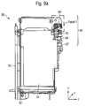
- the removal device 80 has a dedicated pivoting device, which will be discussed in detail below with reference to FIGS. 9a-9d and 10a-10b. In the example shown in Fig. 1, therefore, the removal device 80 is merely indicated, wherein the pivoting direction of this removal device 80 is to be indicated by the dashed line.
- this removal device 80 is positioned such that a goods product 11 'falling out of the goods compartment 10 can fall directly into the opening provided thereon of the removal device 80, which is typically arranged in the upper region of this removal device 80. For this reason, this removal device 80 in the event that a commodity product 11 is to be removed, positioned with its upper part slightly below the goods compartment 10 in the front region 13.
- the holding parts 14, 16 are formed here as a bracket or webs.
- the front bracket 14 has a retaining function and thus serves the purpose of preventing the frontmost box 11 'from tipping out of the goods compartment 10. In the case of a request for goods, this bracket 14 is unlocked, so that thus the foremost commodity product 11 'is released for issue.
- the rear bracket 16 is movable and nestles against the last, provided in the goods receiving area 12 goods product 11 '' to.
- the goods compartment 10 To remove the foremost commodity product 11 'from the goods compartment 10, this has an output area 20 in the front area of the goods compartment 10.
- the goods compartment 10 according to the invention has two transport devices 30 - 33 whose function will be described in detail below.
- the goods compartment 10 has, as the first transport device 30 - 32, a bottom side on the goods compartment 10 provided, circulating conveyor belt 30. Further, two rotatable rollers or rollers 31, 32 are provided on the front and back, over which the conveyor belt 30 is stretched. The upper horizontal region of the treadmill 30 forms the bottom surface 17 of the goods compartment 10.
- the conveyor belt is driven here via at least one of these rollers 31, 32, preferably via the front roller 31. These two rollers 31, 32 are designed to allow a movement of the conveyor belt 30 and thus the goods products 11 thereon toward the dispensing area 20 and thus in the Z direction 21.
- the goods compartment 10 has a second transport device.
- the second transport device is also designed as a rotatable roller or roller 33 or as a relatively short conveyor belt.
- This rotatable roller 33 is, like the rollers 31, 32 of the first transport device, rotatable in the direction of the discharge area 20, so that a movement of a commodity product 11 located on the roll toward the discharge area 20 and thus in the direction 19 is made possible.
- this second transport device 33 is provided in the immediate vicinity of the dispensing area 20 of the goods compartment 10 and is thus arranged in front of the first transport device 30-33. It is also essential that the transport direction of a product on the conveyor belt 30 and on the roller 33 is the same.
- the transport speed v1 of the first transport device 30-33 is lower than the transport speed v2 of the second transport device 33.
- the transport speed v2 is e.g. by at least 50%, preferably by at least 30% and in particular by at least 10% greater than the transport speed v1.
- the rollers 31 - 33 can be driven, for example, by dedicated electric motors (not shown in FIG. 1). Preferably, only a single electric motor is provided for both transport devices 31 - 33, wherein the different transport speeds v1, v2, for example, by varying the diameter of the two rollers 31, 32nd on the one hand and the roller 33 on the other hand, can be realized. In particular, then the roller 33 would have to have a larger diameter. Conceivable, however, would be another implementation of the different speeds, for example, by appropriately sized couplings and gears.
- the two transport devices 30 - 33 are driven by an external drive, that is to say an outside of the goods compartment 10 provided drive, which is therefore not part of the goods compartment 10.
- This drive can preferably be provided via a specially provided removal device, as will be described in detail below with reference to Figures 8, 8a.
- This removal device couples for the removal of a commodity product, for example, to a specially provided Antriebsankoppel issued the goods compartment 10 and drives, for example via corresponding gears and belts (see example in Figure 4), the two drive rollers 31, 33 at.
- the front side bracket 14 is unlocked during the removal process by this drive, whereby the commodity product 11 'can be removed from the goods compartment 10 and fall into a specially provided removal compartment of the removal device.
- the removal device detects this removal of the product by, for example, a product provided on the bottom of the sampling tray pressure or weight sensor and then closes, for example, only after a time required for the Nachschieben the further commodity products 11 to the front page 13 time, the removal process from. As a result, the two transport devices 30 - 33 are stopped and the bracket 14 is locked again. The removal device then moves to a goods delivery shaft of the vending machine, from which the product just taken out of the goods bay can be removed from the buyer.
- the advantage of this embodiment is that the goods compartment 10 does not have to have its own drive device in this case, which is advantageous in particular for cost reasons.
- the conveyor belt 30 is made of plastic, for example of a plastic with a relatively high adhesive friction. If the conveyor belt 30 is moved, then the respective product products 11 standing on the conveyor belt 30 are moved by static friction to the front-side dispensing area 20.
- a goods compartment 10 also knows (not shown in FIG. 1) preferably on the lateral areas of a goods compartment 10 or in the lower area guide elements, for example guide rails or insertion aids, by means of which a goods compartment 10 in corresponding slide rails or guide aids in the space provided for the slot Vending machines can be pushed into it.
- a goods compartment 10 preferably also has a corresponding latching device 24, by means of which the goods compartment 10 can be latched at corresponding latching points on the housing of the vending machine or in the insertion slot and thus fixed there.
- a goods compartment 10 also has a rear wall 23 on the rear side 15.
- the front bracket 14 is fixed in the locked state rigidly and fixed to a housing of the goods compartment 10. Only in the unlocked state can he fold out in the Z direction 21.
- the rear bracket 16 is not rigidly connected to the housing of the goods compartment 10, but preferably moves in the Z-direction 21 with the conveyor belt 30, so that it is ensured that the headband 16 always on the last commodity product 11 " the goods compartment 10 is applied and, for example, a transport-related tilting backwards of a product 11 "prevents.
- the individual goods compartments 10 within a vending machine are flexible in their size, depending on which commodity products are to be sold with them.
- goods compartments 10 can be specifically adapted to the goods to be sold, in particular with regard to their lateral expansions.
- these goods compartments 10 are also removable by pulling out of the interior of the vending machine.
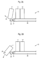
- FIGS. 2a-2c corresponds to the goods compartment 10 shown in FIG. 1, wherein it is shown greatly simplified here.
- FIG. 2a shows a plurality of cans 11, 11 'located on the conveyor belt 30.
- the conveyor belt 30 is driven at a transport speed v1, whereby the Cans 11, 11 'at the transport speed v1 in the Z direction 21, ie in the direction of the discharge area 20, moves.
- the front can 11 'to be removed is located immediately in front of the dispensing area 20.
- the can 11' is still on the conveyor belt 30 of the first transport device.
- the front part of the can 11 ' is already in the range of engagement of the second transport device 33, which rotates at a higher transport speed v2 than the transport speed v1 of the transport belt 30. Because the front part of the can 11 'to be removed is already in engagement with the roller 33 moving at high transport speed v2, the bottom area 36 of the can 11' is pulled in the direction 35, while the upper area of the can 11 'is drawn in inertia - employment still with the lower transport speed v1 is moved.
- the can 11 'to be removed thereby moves away from the further cans 11 of the same goods compartment 10 arranged behind this can 11 (see FIG. 2c), whereby the can 11' to be removed is effectively pulled away "the ground under the feet", so that this can 11 'is pulled with its bottom portion 36 forward in the direction of the output range and thus due to its upper portion falls back somewhat to the rear.
- the greater speed of the roller 33 also ensures that a distance between the cans 11 'and 11 is formed. This distance is useful to ensure that the front bracket 14 can swing freely upwards.
- the can 11 'with the bottom region 36 thereby first falls out of the goods compartment 10 via the dispensing region 20.
- the invention thus prevented that the upper portion of the can 11 'tilts forward.
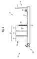
- FIG. 3 shows a side view of a second exemplary embodiment of a merchandise compartment according to the invention for a vending machine.
- the goods compartment 10 does not have a conveyor belt 30 tensioned about two rotatable rollers 31, 32.
- a movable in the Z direction 21 slide 38 is provided.
- This slider 38 forms the first transport device, while the front roller or roller 33 forms the second transport device.
- the slider 38 is mounted on a bottom portion 37 of the housing of the merchandise compartment 10, e.g. a continuous sheet 37, movably mounted in the Z direction.
- the slider 38 thus conforms to the last goods product 11 'located in the goods compartment 10 and pushes it in the Z direction 21 and thus in the direction of the delivery area 20. As a result, all commodity products 11 located in the goods compartment 10 are pushed in the direction of the delivery area 20 ,
- the front-side headband 14 is unlocked here as well.
- the mode of operation is analogous to the mode of operation of the first and second transport devices described with reference to FIGS. 2a-2c.
- the commodity products 11 are pushed by the slider 38 in the direction of the front-side discharge area 20 at a speed v1.
- the foremost commodity product 11 'comes into engagement with the second transport device 33 due to their higher Transport speed v2 the bottom of the commodity product 11 'of the roller 33 of the second transport device 33 quasi pulled away, whereby this commodity 11' falls first with its bottom portion on the output portion 20 in a removal device, not shown in Figure 3.
- the transport speed v2 of the second transport device 33 embodied as a roller 33 is at least greater than the transport speed v1, with which the first transport device 38 designed as a slide 38 is moved in the Z direction 21.
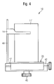
- FIG. 4 shows a front view of a goods compartment 10 according to the invention.
- a front panel 42 immediately before the second transport device 33 designed as a roller 33 - Example for their protection - is provided.
- a lateral housing part 43 is provided for fastening the retaining clip 13.
- a gear 40 is secured in the lower region of the goods compartment 10 at the bottom thereof.
- the gear 40 is slightly from the goods compartment 10 from. If a corresponding, to this gear 40 matching gear, for example via an external drive (not shown in Figure 4), brought into engagement with this gear 40, then the gear 40 undergoes a rotational movement. This rotational movement then forms the drive of the goods compartment 10, with which the first and / or the second transport device 30-33, 38 can be driven. This is done by appropriate deflection devices, such as gears and belts, in a manner known per se.
- the goods compartment 10 according to the invention thus does not require a separate drive.
- FIG. 5 shows a frontal plan view of a vending machine according to the invention with a multiplicity of goods compartments according to the invention.
- reference numeral 50 generally indicates a vending machine for dispensing bottles and cans of various shapes, sizes, shapes, and liquid capacities.
- the vending machine 50 generally comprises an outer housing 51 or a cabinet and a front door 53 hinged typically to this housing 51 via hinges 52.
- the front door 53 and the housing 51 together form an interior space 54 for storing the commodity products 10 'to be sold. and accommodate vending machine cooling functions 56 and other vending machine functions.
- the front door 53 comprises a transparent glass or clear plastic disk 55, which, when the front door 53 is closed, for a clear view of the interior 54 of the vending machine 50 and thus the commodity products 10 housed therein, in the interior 54 of Vending machines 50 are kept in an orderly manner in goods compartments.
- a suitable control panel 56 is provided, which comprises product selection input devices and money and credit processing devices, which are well known as well as a coin return device 57.
- the vending machine 50 also includes a goods issue opening 59 from which a sold commodity 10 can be removed by a buyer.
- the vending machine 50 has a plurality of array réelle in the interior 54 arranged goods compartments 10.
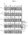
- FIG. 6 shows the arrangement of these goods compartments 10 in the interior 54 of the vending machine 50.
- the individual goods compartments 10 are arranged here in five different product lines 60 and eight different product compartments 61 side by side or one above the other.
- the individual goods compartments 10 each have the same size here, although this is not absolutely necessary. As has already been described in detail above, it is also advantageous if these goods compartments 10 are variably adjustable in their width and / or in their height.
- a specially provided removal device 62 is provided for the removal of the commodity products, which are not shown in Figure 6, from the various goods compartments 10 .
- This removal device 62 can be moved variably in Y-direction 63 and X-direction 64 and can thus be moved to any front side of a goods compartment 10. This is done via a not shown here, in the X / Y direction variable movable transport device to which the removal device 62 is attached.
- This transport device may for example contain guide rails on which the removal device 62 in the Y-direction 63 and X-direction 64 is movable.
- Figure 7 shows a side view of the interior 54 of the vending machine 50 of Figure 6.
- the individual goods compartments 10 are not completely horizontal, that is horizontal, aligned. Rather, the goods compartments 10 are slightly lowered towards the front door side.
- the goods compartments 10 are aligned completely horizontally (as in FIGS. 1-4).
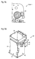
- Figures 8 and 8a show an embodiment of a removal device for a vending machine in two different views, in which Figure 8 shows a frontal view from the front and Figure 8a shows a top view of the removal device 80.
- reference numeral 80 designates the removal device.
- the removal device 80 essentially comprises a cuboid container, with four side walls and a bottom.
- the removal device 80 is designed for removal of a single product 11 and product is designed to be open at the top.
- a removal compartment is defined in the interior of the housing 81 by the cuboid housing 81 of the removal device 80, which serves to receive a commodity product 11.
- a gear designated by reference numeral 83 is fastened via a fastening device 84.
- an electric motor 85 is provided, which is fixed to the right side wall 86 of the housing 81.
- the gear 83 is driven by the electric motor 85, wherein the gear belt 87 in corresponding Gears which are coupled via shafts with the gear 83 and the electric motor 85 engages.
- the gear 83 engages in a corresponding gear 40 (see FIG. 4) of the removal compartment 10 and drives it.
- the first and second transport device can be driven via the electric motor 85 of the removal device 80 and by means of the gear belt 87, the gear 83 and the single-sided gear 40, as already shown and described with reference to FIGS.
- the removal device 80 further has in the upper region of the housing 81, a roller 88 which is driven by a further gear 89.
- the gear 89 is also driven by the electric motor 85 in a known manner via corresponding Umlenk leopard scholar and belts.
- This roller 88 is advantageous, but not necessarily required.
- This roller 88 facilitates, similar to the second transport device of the goods compartment 10, that a goods product 11 'removed from a goods compartment 10 first falls with the floor into the interior of the removal device 80 and thus into its removal compartment 90.
- the roller 88 rotates in the same direction of rotation as the roller 33 of the second transport device.
- the roller 88 may be provided in addition to the second transport device 33 or instead of the second transport device 33. In the event that the roller 88 is provided instead of the second transport device 33, this should also have an at least higher transport speed v2 than the transport speed v1 of the first transport device.
- the z. B. forms the second transport device 33
- the removal device 80 has a pivotable housing flap 91 on the left side of the housing. This pivotable housing flap 91 is pivotally mounted on a rotational axis 92 in the upper region of the housing 81. If the removal device 80 is moved to an output compartment of the vending machine, then the goods product 11 located in the removal compartment 90 can enter the goods delivery compartment by moving the pivotable flap 91 in the direction 93. The goods product 11 located in the removal compartment 90 can then fall from the removal device 80 into the goods issue of the vending machine.
- a tab, a conveyor belt or the like may be clamped inside the removal device 80 in such a way that commodity products located within the removal device 80 can be utilized with a certain incline, e.g. is accomplished by tightening this tab, can fall over the flap 91 to the outside.
- This lanyard supporting a removal of a commodity product will be explained in more detail below with reference to FIGS. 9a and 9b.
- Figures 9a-9d show different views of another embodiment of a removal device according to the invention.
- FIGS. 9a-9b show a removal device according to the invention, which is attached to a pivoting device of the vending machine.
- FIG. 9d shows the shopping cart 80 from FIGS. 9a and 9b in a perspective view.
- FIGS. 9a and 9b are intended to illustrate more precisely the pivoting of the removal device 80 embodied as a shopping basket.
- the cart 80 shown in FIGS. 9a to 9d may be e.g. B. correspond to the removal devices shown in Figures 8 and 8a.
- the cart 80 in Figures 9a to 9d no roller 88 but a conveyor belt 94 in its upper receiving area, which z. B. can hold the function of the second transport device.
- Figure 9c the exact structure of this conveyor belt 94 is shown in a detail.
- This conveyor belt 94 like the roller 88 via the electric motor 85, for example via suitable couplings and pulleys, which need not be described here, are driven.
- this conveyor belt 94 could have its own, second electric motor 101 (see also FIGS. 10 a, 10 b), which merely drives this conveyor belt 94.
- the second transport device forming conveyor belt 94 are driven by a separate electric motor 101, wherein the first transport device on the side of the goods compartment 10 to a certain extent indirectly via the electric motor 85, the gears 83 and the gear belt 87 are driven, provided that these gears 83 via a corresponding coupling can be coupled to the first transport device.
- the cart 80 is further on a pivoting device 95, the z. B. can be part of the removal device 62, attached and can be moved over this pivoting device 95 in the X / Y direction, so that the cart 80 can be moved in front of the front side 13 of the juxtaposed and each other goods compartments of a vending machine.
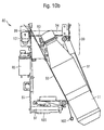
- the shopping cart 80 can pivot about this pivoting device 95 with its upper portion 96 in the Z direction and thus in the direction of the front region of the various goods compartments. This pivoting mechanism is shown in FIG. 9b.
- the pivoting device 95 For pivoting the basket 80 in the Z-direction, the pivoting device 95 has a pivot arm 96 to which the basket 80 is attached and which in turn is attached to the pivoting device 95 about a rotatable pivot axis 97 in the lower region of the pivot arm 96 and the basket 80.
- This pivot axis 97 is typically force-coupled via a third electric motor 103 (see FIGS. 10a, 10b), which is not shown in FIGS. 9a to 9d, and can thus also be correspondingly turned into the desired position via this electric motor 103.
- FIG. 9b for the sake of clarity, the shopping cart 80 is not shown, in order thereby to control the pivoting function of the pivoting arm 96 and thus one of it better to illustrate the attached basket of goods.
- Figure 9b dashed the swivel arm is also shown in the swung-out state.
- FIG. 9b also shows a bracket 100 protruding from the pivoting arm 96 or the shopping cart 80 in the upper area 99. If the pivoting arm 96 is moved in the pivoting direction 98, then the retaining bracket 14 in the front area 13 of a respective pivot bracket 100 can be used in a particularly preferred embodiment
- ressfaches 10 are pressed down, whereby this goods compartment 10 is thus released. In this way, the commodity products 11 located in the respective goods compartment 10 are no longer retained and can be removed via the respective goods compartment 10 associated transport devices and the cart 80.
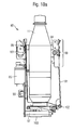
- FIGS. 10a and 10b show side views of a shopping cart 80 according to the invention, in which a product 11 formed as a bottle is provided in the housing interior 90 thereof.
- Figures 10a and 10b are intended to illustrate a removal of this commodity 11 from the cart 80.
- a belt, a flat belt, a belt-shaped band, a tab or the like 93 is provided in the interior 90 of the basket 80, on which the product 11 (see FIG. 10a) can first stand upright.
- This belt-shaped band 93 is clamped in this state between an upper left and a lower right portion of the basket 80 such that the commodity product 11 standing on this band 93 can nevertheless stand perpendicular to this band 93.
- This removal mechanism provides that the element 102 engages or is received in a corresponding receptacle, as long as the goods compartment 80 is moved over the removal direction 62 into the region of the delivery compartment 59.
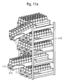
- FIGS. 11a to 11c show a framework-like device 110 for accommodating a plurality of goods compartments 10, this device 110 typically being located in the interior of the housing 54 of a vending machine 50 according to the invention, as it is known, for example.
- B. is shown in Figures 5 to 7, can be arranged.
- 11a shows the device 110 in a perspective view
- FIG. 11b shows the device 110 in a side view.
- the device 110 has a total of 5 merchandiser lines 111, which are arranged one above the other.
- a respective product line 111 has in each case 3 goods compartments 10.
- the commodity products 11 are arranged in the goods compartment 10 one behind the other.
- FIG. 11a to 11c show a framework-like device 110 for accommodating a plurality of goods compartments 10, this device 110 typically being located in the interior of the housing 54 of a vending machine 50 according to the invention, as it is known, for example.
- B. is shown in Figures 5 to 7, can be arranged.
- 11a shows the device 110
- FIGS. 11a and 11b two of these goods compartments 10 are pulled out of the device 110 in order to illustrate a filling process.
- the lower withdrawn goods compartment 10 is only partially pulled out.
- the upper goods compartment 10 is completely pulled out and, in this state, also with its front side 13 inclined slightly downwards, which simplifies a total filling process.
- FIG. 11c shows a detail of the device 110.
- a respective goods compartment 10 has here on its side opposite the front side a spring element 112, which is resiliently coupled to the device 110. If a respective goods compartment is not pushed completely into the corresponding device 110 and, for example, not yet fixed there by means of a latching and locking device 24, then this spring element 112 ensures that the corresponding goods compartment 10 is pressed resiliently out of the device 110 and thus with its Front side 13 defined out of the device 110 protrudes. This can be easily recognized by a user or filler, so that in this way effectively accidental Tin a merchandise compartment 10 in the case of a filling process does not go undetected.
- the present invention has been described in terms of a beverage vending machine for dispensing bottles and beverage cans, it is not limited thereto, but can be extended with appropriate modification to the output of any commodity products, such as cigarette packs, packaged candy products, sandwiches, miscellaneous items such as cameras, glasses and the same.
- a vending machine as shown in Figures 5 to 7, represents only one possible embodiment of such a vending machine, but the invention should not be limited to such a construction. It is only essential here that the individual goods compartments are arranged side by side and one above the other in layers and are oriented more or less vertically. It would also be conceivable in this context that, for example, a plurality of juxtaposed goods compartments and / or several superimposed goods compartments together form a merchandise compartment module in which the goods compartments contained there are fixedly coupled to each other and thus can always be pushed out together and also back into the interior of the vending machine can be pushed. In this case, according to the invention, it would only have to be determined in one of these goods compartments whether it is located in the first or in the second position.
Landscapes
- Physics & Mathematics (AREA)
- General Physics & Mathematics (AREA)
- Vending Machines For Individual Products (AREA)
- Control Of Vending Devices And Auxiliary Devices For Vending Devices (AREA)
Applications Claiming Priority (1)
| Application Number | Priority Date | Filing Date | Title |
|---|---|---|---|
| DE102006051107 | 2006-10-25 |
Publications (3)
| Publication Number | Publication Date |
|---|---|
| EP1947619A2 true EP1947619A2 (fr) | 2008-07-23 |
| EP1947619A3 EP1947619A3 (fr) | 2009-08-05 |
| EP1947619B1 EP1947619B1 (fr) | 2015-03-04 |
Family
ID=39146902
Family Applications (1)
| Application Number | Title | Priority Date | Filing Date |
|---|---|---|---|
| EP07119303.1A Not-in-force EP1947619B1 (fr) | 2006-10-25 | 2007-10-25 | Rayon de marchandises, dispositif de prélèvement, automate de vente et procédé |
Country Status (1)
| Country | Link |
|---|---|
| EP (1) | EP1947619B1 (fr) |
Cited By (9)
| Publication number | Priority date | Publication date | Assignee | Title |
|---|---|---|---|---|
| EP2568453A1 (fr) * | 2011-09-08 | 2013-03-13 | Sielaff Gmbh & Co. Kg Automatenbau | Rayon de marchandises, dispositif de prélèvement, automate de vente et procédé |
| CN107424309A (zh) * | 2017-09-29 | 2017-12-01 | 重庆智高美科技有限公司 | 一种精准出货方法及智能贩卖机 |
| CN107472425A (zh) * | 2017-08-23 | 2017-12-15 | 重庆迪洋科技开发有限公司 | 一种送货三轮车 |
| CN109767561A (zh) * | 2019-01-28 | 2019-05-17 | 百特(福建)智能装备科技有限公司 | 一种自动售货机货道及自动售货机 |
| CN110223460A (zh) * | 2019-05-24 | 2019-09-10 | 吴光淼 | 一种基于区块链的影院3d影片售票取票一体机 |
| CN112233321A (zh) * | 2020-10-13 | 2021-01-15 | 和县小辣椒电子商务有限公司 | 一种卷烟零售用储存盒推送防盗装置及其使用方法 |
| CN113593113A (zh) * | 2021-07-27 | 2021-11-02 | 上海欣巴科技设备有限公司 | 一种发药机 |
| WO2022039958A1 (fr) * | 2020-08-19 | 2022-02-24 | Pepsico, Inc. | Mécanisme de distribution de produits pour distributeur automatique |
| WO2025137735A1 (fr) * | 2023-12-21 | 2025-06-26 | Toan Nguyen Dinh | Mécanisme de chute et de soutien de produit pour distributeurs automatiques |
Families Citing this family (1)
| Publication number | Priority date | Publication date | Assignee | Title |
|---|---|---|---|---|
| CN109389746A (zh) * | 2018-10-05 | 2019-02-26 | 邢二江 | 一种自动化售货机 |
Citations (1)
| Publication number | Priority date | Publication date | Assignee | Title |
|---|---|---|---|---|
| EP1329398A1 (fr) | 2002-01-11 | 2003-07-23 | B Plus Development (Société Anonyme) | Procédé et installation automatisée de stockage et de distribution d'objects ou articles divers |
Family Cites Families (3)
| Publication number | Priority date | Publication date | Assignee | Title |
|---|---|---|---|---|
| FR2607482A1 (fr) * | 1986-04-17 | 1988-06-03 | Arci | Dispositif permettant de distribuer un par un des objets de taille et de forme irregulieres |
| JP3923295B2 (ja) * | 2001-10-22 | 2007-05-30 | サンデン株式会社 | 自動販売機 |
| JP2006011584A (ja) * | 2004-06-23 | 2006-01-12 | Sanden Corp | 自動販売機 |
-
2007
- 2007-10-25 EP EP07119303.1A patent/EP1947619B1/fr not_active Not-in-force
Patent Citations (1)
| Publication number | Priority date | Publication date | Assignee | Title |
|---|---|---|---|---|
| EP1329398A1 (fr) | 2002-01-11 | 2003-07-23 | B Plus Development (Société Anonyme) | Procédé et installation automatisée de stockage et de distribution d'objects ou articles divers |
Cited By (15)
| Publication number | Priority date | Publication date | Assignee | Title |
|---|---|---|---|---|
| DE102011082378A1 (de) * | 2011-09-08 | 2013-03-14 | Sielaff Gmbh & Co. Kg Automatenbau | Warenfach, Verkaufsautomat und Verfahren |
| DE102011082378B4 (de) * | 2011-09-08 | 2013-04-25 | Sielaff Gmbh & Co. Kg Automatenbau | Warenfach, Verkaufsautomat und Verfahren |
| EP2568453A1 (fr) * | 2011-09-08 | 2013-03-13 | Sielaff Gmbh & Co. Kg Automatenbau | Rayon de marchandises, dispositif de prélèvement, automate de vente et procédé |
| CN107472425A (zh) * | 2017-08-23 | 2017-12-15 | 重庆迪洋科技开发有限公司 | 一种送货三轮车 |
| CN107424309A (zh) * | 2017-09-29 | 2017-12-01 | 重庆智高美科技有限公司 | 一种精准出货方法及智能贩卖机 |
| CN109767561B (zh) * | 2019-01-28 | 2024-03-01 | 百特(福建)智能装备科技有限公司 | 一种自动售货机货道及自动售货机 |
| CN109767561A (zh) * | 2019-01-28 | 2019-05-17 | 百特(福建)智能装备科技有限公司 | 一种自动售货机货道及自动售货机 |
| CN110223460A (zh) * | 2019-05-24 | 2019-09-10 | 吴光淼 | 一种基于区块链的影院3d影片售票取票一体机 |
| WO2022039958A1 (fr) * | 2020-08-19 | 2022-02-24 | Pepsico, Inc. | Mécanisme de distribution de produits pour distributeur automatique |
| CN115867951A (zh) * | 2020-08-19 | 2023-03-28 | 百事可乐公司 | 用于自动售货机的产品递送机构 |
| EP4200822A4 (fr) * | 2020-08-19 | 2024-04-03 | Pepsico Inc | Mécanisme de distribution de produits pour distributeur automatique |
| EP4200822B1 (fr) | 2020-08-19 | 2025-06-04 | PepsiCo, Inc. | Mécanisme de distribution de produits pour distributeur automatique |
| CN112233321A (zh) * | 2020-10-13 | 2021-01-15 | 和县小辣椒电子商务有限公司 | 一种卷烟零售用储存盒推送防盗装置及其使用方法 |
| CN113593113A (zh) * | 2021-07-27 | 2021-11-02 | 上海欣巴科技设备有限公司 | 一种发药机 |
| WO2025137735A1 (fr) * | 2023-12-21 | 2025-06-26 | Toan Nguyen Dinh | Mécanisme de chute et de soutien de produit pour distributeurs automatiques |
Also Published As
| Publication number | Publication date |
|---|---|
| EP1947619A3 (fr) | 2009-08-05 |
| EP1947619B1 (fr) | 2015-03-04 |
Similar Documents
| Publication | Publication Date | Title |
|---|---|---|
| EP1947619B1 (fr) | Rayon de marchandises, dispositif de prélèvement, automate de vente et procédé | |
| DE69826305T2 (de) | Vorrichtung und verfahren zum verkaufen von erzeugnissen | |
| EP1119830B1 (fr) | Distributeur automatique de cigarettes | |
| DE60309873T2 (de) | Vorrichtung und verfahren zum verkaufen von produkten in verschiedenen grössen | |
| DE3789709T2 (de) | Ausgeber für flache Gegenstände. | |
| EP2568452B1 (fr) | Dispositif de sortie de marchandises, automate de vente et procédé | |
| EP1916633B1 (fr) | Rayon de sortie, automate de vente et procédé | |
| DE19604561A1 (de) | Vorrichtung zur Ausgabe von Zigarettenschachteln | |
| EP1133760B1 (fr) | Distributeur automatique de marchandises a plusieurs compartiments de marchandises superposes | |
| EP2568453B1 (fr) | Rayon de marchandises, dispositif de prélèvement, automate de vente et procédé | |
| DE102015212271B3 (de) | Liftvorrichtung, Warenautomat | |
| WO2017021456A1 (fr) | Système de distribution d'articles | |
| EP2031568A1 (fr) | Dispositif de vente et procédé de fonctionnement d'une telle machine de vente ainsi que produit pour une telle machine de vente | |
| EP0991036B1 (fr) | Distributeur | |
| EP3467795A1 (fr) | Distributeur automatique | |
| DE2850214A1 (de) | Ausgabevorrichtung fuer verkaufsautomaten u.dgl. | |
| EP1851733B1 (fr) | Commande sequentielle pour un distributeur automatique | |
| EP3786910B1 (fr) | Distribution ergonomique d'un distributeur automatique | |
| EP4488972A1 (fr) | Station de vente pour la distribution automatique de marchandises à un acheteur | |
| DE9101337U1 (de) | Automat zur Selbstbedienung mit erwärmten Menü-Packungen | |
| EP4485411A1 (fr) | Dispositif de réception destiné à recevoir ou à distribuer des produits dans un automate combiné | |
| DE102023118037A1 (de) | Verkaufsautomat zur Lagerung und Abgabe einer Ware, Verkaufsautomatenstation zur automatischen Ausgabe von Waren an einen Käufer sowie Verfahren zur Ausgabe einer Ware aus einem Verkaufsautomaten | |
| DE102011110302A1 (de) | Warenlager und Warenlagerungseinheit dafür | |
| DE102020104578A1 (de) | Vorrichtung mit einem Gehäuse zur Aufnahme von Kleinartikeln | |
| DE29904863U1 (de) | Ausgabeautomat |
Legal Events
| Date | Code | Title | Description |
|---|---|---|---|
| PUAI | Public reference made under article 153(3) epc to a published international application that has entered the european phase |
Free format text: ORIGINAL CODE: 0009012 |
|
| AK | Designated contracting states |
Kind code of ref document: A2 Designated state(s): AT BE BG CH CY CZ DE DK EE ES FI FR GB GR HU IE IS IT LI LT LU LV MC MT NL PL PT RO SE SI SK TR |
|
| AX | Request for extension of the european patent |
Extension state: AL BA HR MK RS |
|
| PUAL | Search report despatched |
Free format text: ORIGINAL CODE: 0009013 |
|
| AK | Designated contracting states |
Kind code of ref document: A3 Designated state(s): AT BE BG CH CY CZ DE DK EE ES FI FR GB GR HU IE IS IT LI LT LU LV MC MT NL PL PT RO SE SI SK TR |
|
| AX | Request for extension of the european patent |
Extension state: AL BA HR MK RS |
|
| 17P | Request for examination filed |
Effective date: 20100118 |
|
| AKX | Designation fees paid |
Designated state(s): AT BE BG CH CY CZ DE DK EE ES FI FR GB GR HU IE IS IT LI LT LU LV MC MT NL PL PT RO SE SI SK TR |
|
| 17Q | First examination report despatched |
Effective date: 20130917 |
|
| GRAP | Despatch of communication of intention to grant a patent |
Free format text: ORIGINAL CODE: EPIDOSNIGR1 |
|
| INTG | Intention to grant announced |
Effective date: 20141020 |
|
| GRAS | Grant fee paid |
Free format text: ORIGINAL CODE: EPIDOSNIGR3 |
|
| GRAA | (expected) grant |
Free format text: ORIGINAL CODE: 0009210 |
|
| AK | Designated contracting states |
Kind code of ref document: B1 Designated state(s): AT BE BG CH CY CZ DE DK EE ES FI FR GB GR HU IE IS IT LI LT LU LV MC MT NL PL PT RO SE SI SK TR |
|
| REG | Reference to a national code |
Ref country code: GB Ref legal event code: FG4D Free format text: NOT ENGLISH |
|
| REG | Reference to a national code |
Ref country code: CH Ref legal event code: EP |
|
| REG | Reference to a national code |
Ref country code: IE Ref legal event code: FG4D Free format text: LANGUAGE OF EP DOCUMENT: GERMAN |
|
| REG | Reference to a national code |
Ref country code: AT Ref legal event code: REF Ref document number: 714437 Country of ref document: AT Kind code of ref document: T Effective date: 20150415 |
|
| REG | Reference to a national code |
Ref country code: DE Ref legal event code: R096 Ref document number: 502007013764 Country of ref document: DE Effective date: 20150416 |
|
| REG | Reference to a national code |
Ref country code: NL Ref legal event code: VDEP Effective date: 20150304 |
|
| PG25 | Lapsed in a contracting state [announced via postgrant information from national office to epo] |
Ref country code: SE Free format text: LAPSE BECAUSE OF FAILURE TO SUBMIT A TRANSLATION OF THE DESCRIPTION OR TO PAY THE FEE WITHIN THE PRESCRIBED TIME-LIMIT Effective date: 20150304 Ref country code: ES Free format text: LAPSE BECAUSE OF FAILURE TO SUBMIT A TRANSLATION OF THE DESCRIPTION OR TO PAY THE FEE WITHIN THE PRESCRIBED TIME-LIMIT Effective date: 20150304 Ref country code: FI Free format text: LAPSE BECAUSE OF FAILURE TO SUBMIT A TRANSLATION OF THE DESCRIPTION OR TO PAY THE FEE WITHIN THE PRESCRIBED TIME-LIMIT Effective date: 20150304 Ref country code: LT Free format text: LAPSE BECAUSE OF FAILURE TO SUBMIT A TRANSLATION OF THE DESCRIPTION OR TO PAY THE FEE WITHIN THE PRESCRIBED TIME-LIMIT Effective date: 20150304 |
|
| REG | Reference to a national code |
Ref country code: LT Ref legal event code: MG4D |
|
| PG25 | Lapsed in a contracting state [announced via postgrant information from national office to epo] |
Ref country code: LV Free format text: LAPSE BECAUSE OF FAILURE TO SUBMIT A TRANSLATION OF THE DESCRIPTION OR TO PAY THE FEE WITHIN THE PRESCRIBED TIME-LIMIT Effective date: 20150304 Ref country code: GR Free format text: LAPSE BECAUSE OF FAILURE TO SUBMIT A TRANSLATION OF THE DESCRIPTION OR TO PAY THE FEE WITHIN THE PRESCRIBED TIME-LIMIT Effective date: 20150605 |
|
| PG25 | Lapsed in a contracting state [announced via postgrant information from national office to epo] |
Ref country code: NL Free format text: LAPSE BECAUSE OF FAILURE TO SUBMIT A TRANSLATION OF THE DESCRIPTION OR TO PAY THE FEE WITHIN THE PRESCRIBED TIME-LIMIT Effective date: 20150304 |
|
| REG | Reference to a national code |
Ref country code: FR Ref legal event code: PLFP Year of fee payment: 9 |
|
| PG25 | Lapsed in a contracting state [announced via postgrant information from national office to epo] |
Ref country code: EE Free format text: LAPSE BECAUSE OF FAILURE TO SUBMIT A TRANSLATION OF THE DESCRIPTION OR TO PAY THE FEE WITHIN THE PRESCRIBED TIME-LIMIT Effective date: 20150304 Ref country code: SK Free format text: LAPSE BECAUSE OF FAILURE TO SUBMIT A TRANSLATION OF THE DESCRIPTION OR TO PAY THE FEE WITHIN THE PRESCRIBED TIME-LIMIT Effective date: 20150304 Ref country code: RO Free format text: LAPSE BECAUSE OF FAILURE TO SUBMIT A TRANSLATION OF THE DESCRIPTION OR TO PAY THE FEE WITHIN THE PRESCRIBED TIME-LIMIT Effective date: 20150304 Ref country code: CZ Free format text: LAPSE BECAUSE OF FAILURE TO SUBMIT A TRANSLATION OF THE DESCRIPTION OR TO PAY THE FEE WITHIN THE PRESCRIBED TIME-LIMIT Effective date: 20150304 Ref country code: PT Free format text: LAPSE BECAUSE OF FAILURE TO SUBMIT A TRANSLATION OF THE DESCRIPTION OR TO PAY THE FEE WITHIN THE PRESCRIBED TIME-LIMIT Effective date: 20150706 |
|
| PG25 | Lapsed in a contracting state [announced via postgrant information from national office to epo] |
Ref country code: PL Free format text: LAPSE BECAUSE OF FAILURE TO SUBMIT A TRANSLATION OF THE DESCRIPTION OR TO PAY THE FEE WITHIN THE PRESCRIBED TIME-LIMIT Effective date: 20150304 Ref country code: IS Free format text: LAPSE BECAUSE OF FAILURE TO SUBMIT A TRANSLATION OF THE DESCRIPTION OR TO PAY THE FEE WITHIN THE PRESCRIBED TIME-LIMIT Effective date: 20150704 |
|
| REG | Reference to a national code |
Ref country code: DE Ref legal event code: R097 Ref document number: 502007013764 Country of ref document: DE |
|
| PLBE | No opposition filed within time limit |
Free format text: ORIGINAL CODE: 0009261 |
|
| STAA | Information on the status of an ep patent application or granted ep patent |
Free format text: STATUS: NO OPPOSITION FILED WITHIN TIME LIMIT |
|
| PG25 | Lapsed in a contracting state [announced via postgrant information from national office to epo] |
Ref country code: DK Free format text: LAPSE BECAUSE OF FAILURE TO SUBMIT A TRANSLATION OF THE DESCRIPTION OR TO PAY THE FEE WITHIN THE PRESCRIBED TIME-LIMIT Effective date: 20150304 |
|
| 26N | No opposition filed |
Effective date: 20151207 |
|
| PG25 | Lapsed in a contracting state [announced via postgrant information from national office to epo] |
Ref country code: SI Free format text: LAPSE BECAUSE OF FAILURE TO SUBMIT A TRANSLATION OF THE DESCRIPTION OR TO PAY THE FEE WITHIN THE PRESCRIBED TIME-LIMIT Effective date: 20150304 |
|
| PG25 | Lapsed in a contracting state [announced via postgrant information from national office to epo] |
Ref country code: LU Free format text: LAPSE BECAUSE OF FAILURE TO SUBMIT A TRANSLATION OF THE DESCRIPTION OR TO PAY THE FEE WITHIN THE PRESCRIBED TIME-LIMIT Effective date: 20151025 |
|
| REG | Reference to a national code |
Ref country code: CH Ref legal event code: PL |
|
| PG25 | Lapsed in a contracting state [announced via postgrant information from national office to epo] |
Ref country code: MC Free format text: LAPSE BECAUSE OF FAILURE TO SUBMIT A TRANSLATION OF THE DESCRIPTION OR TO PAY THE FEE WITHIN THE PRESCRIBED TIME-LIMIT Effective date: 20150304 |
|
| REG | Reference to a national code |
Ref country code: IE Ref legal event code: MM4A |
|
| PG25 | Lapsed in a contracting state [announced via postgrant information from national office to epo] |
Ref country code: LI Free format text: LAPSE BECAUSE OF NON-PAYMENT OF DUE FEES Effective date: 20151031 Ref country code: CH Free format text: LAPSE BECAUSE OF NON-PAYMENT OF DUE FEES Effective date: 20151031 |
|
| REG | Reference to a national code |
Ref country code: FR Ref legal event code: PLFP Year of fee payment: 10 |
|
| PG25 | Lapsed in a contracting state [announced via postgrant information from national office to epo] |
Ref country code: IE Free format text: LAPSE BECAUSE OF NON-PAYMENT OF DUE FEES Effective date: 20151025 |
|
| REG | Reference to a national code |
Ref country code: AT Ref legal event code: MM01 Ref document number: 714437 Country of ref document: AT Kind code of ref document: T Effective date: 20151025 |
|
| PGFP | Annual fee paid to national office [announced via postgrant information from national office to epo] |
Ref country code: GB Payment date: 20161020 Year of fee payment: 10 |
|
| PG25 | Lapsed in a contracting state [announced via postgrant information from national office to epo] |
Ref country code: AT Free format text: LAPSE BECAUSE OF NON-PAYMENT OF DUE FEES Effective date: 20151025 |
|
| PG25 | Lapsed in a contracting state [announced via postgrant information from national office to epo] |
Ref country code: BG Free format text: LAPSE BECAUSE OF FAILURE TO SUBMIT A TRANSLATION OF THE DESCRIPTION OR TO PAY THE FEE WITHIN THE PRESCRIBED TIME-LIMIT Effective date: 20150304 Ref country code: HU Free format text: LAPSE BECAUSE OF FAILURE TO SUBMIT A TRANSLATION OF THE DESCRIPTION OR TO PAY THE FEE WITHIN THE PRESCRIBED TIME-LIMIT; INVALID AB INITIO Effective date: 20071025 |
|
| PG25 | Lapsed in a contracting state [announced via postgrant information from national office to epo] |
Ref country code: CY Free format text: LAPSE BECAUSE OF FAILURE TO SUBMIT A TRANSLATION OF THE DESCRIPTION OR TO PAY THE FEE WITHIN THE PRESCRIBED TIME-LIMIT Effective date: 20150304 |
|
| PG25 | Lapsed in a contracting state [announced via postgrant information from national office to epo] |
Ref country code: BE Free format text: LAPSE BECAUSE OF NON-PAYMENT OF DUE FEES Effective date: 20151031 |
|
| PG25 | Lapsed in a contracting state [announced via postgrant information from national office to epo] |
Ref country code: TR Free format text: LAPSE BECAUSE OF FAILURE TO SUBMIT A TRANSLATION OF THE DESCRIPTION OR TO PAY THE FEE WITHIN THE PRESCRIBED TIME-LIMIT Effective date: 20150304 Ref country code: MT Free format text: LAPSE BECAUSE OF FAILURE TO SUBMIT A TRANSLATION OF THE DESCRIPTION OR TO PAY THE FEE WITHIN THE PRESCRIBED TIME-LIMIT Effective date: 20150304 |
|
| REG | Reference to a national code |
Ref country code: FR Ref legal event code: PLFP Year of fee payment: 11 |
|
| GBPC | Gb: european patent ceased through non-payment of renewal fee |
Effective date: 20171025 |
|
| PG25 | Lapsed in a contracting state [announced via postgrant information from national office to epo] |
Ref country code: GB Free format text: LAPSE BECAUSE OF NON-PAYMENT OF DUE FEES Effective date: 20171025 |
|
| REG | Reference to a national code |
Ref country code: FR Ref legal event code: PLFP Year of fee payment: 12 |
|
| PGFP | Annual fee paid to national office [announced via postgrant information from national office to epo] |
Ref country code: IE Payment date: 20181219 Year of fee payment: 9 |
|
| PG25 | Lapsed in a contracting state [announced via postgrant information from national office to epo] |
Ref country code: FR Free format text: LAPSE BECAUSE OF NON-PAYMENT OF DUE FEES Effective date: 20191031 |
|
| PGFP | Annual fee paid to national office [announced via postgrant information from national office to epo] |
Ref country code: DE Payment date: 20201030 Year of fee payment: 14 Ref country code: IT Payment date: 20201026 Year of fee payment: 14 |
|
| REG | Reference to a national code |
Ref country code: DE Ref legal event code: R119 Ref document number: 502007013764 Country of ref document: DE |
|
| PG25 | Lapsed in a contracting state [announced via postgrant information from national office to epo] |
Ref country code: DE Free format text: LAPSE BECAUSE OF NON-PAYMENT OF DUE FEES Effective date: 20220503 |
|
| PG25 | Lapsed in a contracting state [announced via postgrant information from national office to epo] |
Ref country code: IT Free format text: LAPSE BECAUSE OF NON-PAYMENT OF DUE FEES Effective date: 20211025 |