EP1945446B1 - Produit semi-fini plat conformé, composant structurel ou hybride et procédé de fabrication d'un tel produit semi-fini ou d'un tel composant - Google Patents
Produit semi-fini plat conformé, composant structurel ou hybride et procédé de fabrication d'un tel produit semi-fini ou d'un tel composant Download PDFInfo
- Publication number
- EP1945446B1 EP1945446B1 EP06818402.7A EP06818402A EP1945446B1 EP 1945446 B1 EP1945446 B1 EP 1945446B1 EP 06818402 A EP06818402 A EP 06818402A EP 1945446 B1 EP1945446 B1 EP 1945446B1
- Authority
- EP
- European Patent Office
- Prior art keywords
- insert
- injection
- deformed
- plastic
- region
- Prior art date
- Legal status (The legal status is an assumption and is not a legal conclusion. Google has not performed a legal analysis and makes no representation as to the accuracy of the status listed.)
- Active
Links
- 238000004519 manufacturing process Methods 0.000 title claims description 44
- 229910052751 metal Inorganic materials 0.000 claims description 84
- 239000002184 metal Substances 0.000 claims description 84
- 238000000034 method Methods 0.000 claims description 48
- 239000011324 bead Substances 0.000 claims description 42
- 239000004033 plastic Substances 0.000 claims description 41
- 229920003023 plastic Polymers 0.000 claims description 41
- 239000000155 melt Substances 0.000 claims description 35
- 238000001746 injection moulding Methods 0.000 claims description 32
- 239000002991 molded plastic Substances 0.000 claims description 31
- 239000002131 composite material Substances 0.000 claims description 26
- 239000000463 material Substances 0.000 claims description 25
- 239000011265 semifinished product Substances 0.000 claims description 20
- 230000003014 reinforcing effect Effects 0.000 claims description 10
- 229920002430 Fibre-reinforced plastic Polymers 0.000 claims 1
- 239000011151 fibre-reinforced plastic Substances 0.000 claims 1
- 230000008569 process Effects 0.000 description 24
- FYYHWMGAXLPEAU-UHFFFAOYSA-N Magnesium Chemical compound [Mg] FYYHWMGAXLPEAU-UHFFFAOYSA-N 0.000 description 21
- XAGFODPZIPBFFR-UHFFFAOYSA-N aluminium Chemical compound [Al] XAGFODPZIPBFFR-UHFFFAOYSA-N 0.000 description 21
- 238000002347 injection Methods 0.000 description 21
- 239000007924 injection Substances 0.000 description 21
- 229910052782 aluminium Inorganic materials 0.000 description 20
- 238000010586 diagram Methods 0.000 description 20
- 239000011777 magnesium Substances 0.000 description 16
- 229910052749 magnesium Inorganic materials 0.000 description 16
- 238000013461 design Methods 0.000 description 15
- 230000010354 integration Effects 0.000 description 10
- 238000010276 construction Methods 0.000 description 8
- 238000005516 engineering process Methods 0.000 description 7
- 238000000465 moulding Methods 0.000 description 7
- 238000012360 testing method Methods 0.000 description 7
- 229910000831 Steel Inorganic materials 0.000 description 6
- 238000004886 process control Methods 0.000 description 6
- 239000010959 steel Substances 0.000 description 6
- 230000008901 benefit Effects 0.000 description 5
- 150000001875 compounds Chemical class 0.000 description 5
- 230000001419 dependent effect Effects 0.000 description 3
- 238000007781 pre-processing Methods 0.000 description 3
- 238000012545 processing Methods 0.000 description 3
- 229920001169 thermoplastic Polymers 0.000 description 3
- 239000004416 thermosoftening plastic Substances 0.000 description 3
- 229920010540 PA6 GF30 Polymers 0.000 description 2
- 229920006920 PA6-GF30 Polymers 0.000 description 2
- 238000004026 adhesive bonding Methods 0.000 description 2
- 238000004873 anchoring Methods 0.000 description 2
- 238000005452 bending Methods 0.000 description 2
- 238000005336 cracking Methods 0.000 description 2
- 238000011161 development Methods 0.000 description 2
- 230000018109 developmental process Effects 0.000 description 2
- 238000009826 distribution Methods 0.000 description 2
- 230000008030 elimination Effects 0.000 description 2
- 238000003379 elimination reaction Methods 0.000 description 2
- 238000010438 heat treatment Methods 0.000 description 2
- 230000000977 initiatory effect Effects 0.000 description 2
- 238000005304 joining Methods 0.000 description 2
- 239000007788 liquid Substances 0.000 description 2
- 150000002739 metals Chemical class 0.000 description 2
- 238000002360 preparation method Methods 0.000 description 2
- 230000009467 reduction Effects 0.000 description 2
- 230000002787 reinforcement Effects 0.000 description 2
- 238000004904 shortening Methods 0.000 description 2
- 229910000838 Al alloy Inorganic materials 0.000 description 1
- 229910000861 Mg alloy Inorganic materials 0.000 description 1
- 239000000853 adhesive Substances 0.000 description 1
- 230000001070 adhesive effect Effects 0.000 description 1
- 230000015572 biosynthetic process Effects 0.000 description 1
- 238000009529 body temperature measurement Methods 0.000 description 1
- 239000004918 carbon fiber reinforced polymer Substances 0.000 description 1
- 239000000969 carrier Substances 0.000 description 1
- 230000008859 change Effects 0.000 description 1
- 238000012512 characterization method Methods 0.000 description 1
- 230000001427 coherent effect Effects 0.000 description 1
- 238000007796 conventional method Methods 0.000 description 1
- 230000007423 decrease Effects 0.000 description 1
- 238000001514 detection method Methods 0.000 description 1
- 230000006866 deterioration Effects 0.000 description 1
- 238000006073 displacement reaction Methods 0.000 description 1
- 239000013013 elastic material Substances 0.000 description 1
- 238000002474 experimental method Methods 0.000 description 1
- 239000011152 fibreglass Substances 0.000 description 1
- 230000006872 improvement Effects 0.000 description 1
- 238000007373 indentation Methods 0.000 description 1
- 238000012986 modification Methods 0.000 description 1
- 230000004048 modification Effects 0.000 description 1
- 230000008450 motivation Effects 0.000 description 1
- 238000005457 optimization Methods 0.000 description 1
- 239000002985 plastic film Substances 0.000 description 1
- 229920000642 polymer Polymers 0.000 description 1
- 238000007493 shaping process Methods 0.000 description 1
- 230000003068 static effect Effects 0.000 description 1
- 239000000126 substance Substances 0.000 description 1
- 230000009466 transformation Effects 0.000 description 1
- 238000000844 transformation Methods 0.000 description 1
Images


Classifications
-
- B—PERFORMING OPERATIONS; TRANSPORTING
- B29—WORKING OF PLASTICS; WORKING OF SUBSTANCES IN A PLASTIC STATE IN GENERAL
- B29C—SHAPING OR JOINING OF PLASTICS; SHAPING OF MATERIAL IN A PLASTIC STATE, NOT OTHERWISE PROVIDED FOR; AFTER-TREATMENT OF THE SHAPED PRODUCTS, e.g. REPAIRING
- B29C45/00—Injection moulding, i.e. forcing the required volume of moulding material through a nozzle into a closed mould; Apparatus therefor
- B29C45/14—Injection moulding, i.e. forcing the required volume of moulding material through a nozzle into a closed mould; Apparatus therefor incorporating preformed parts or layers, e.g. injection moulding around inserts or for coating articles
- B29C45/1418—Injection moulding, i.e. forcing the required volume of moulding material through a nozzle into a closed mould; Apparatus therefor incorporating preformed parts or layers, e.g. injection moulding around inserts or for coating articles the inserts being deformed or preformed, e.g. by the injection pressure
-
- B—PERFORMING OPERATIONS; TRANSPORTING
- B29—WORKING OF PLASTICS; WORKING OF SUBSTANCES IN A PLASTIC STATE IN GENERAL
- B29C—SHAPING OR JOINING OF PLASTICS; SHAPING OF MATERIAL IN A PLASTIC STATE, NOT OTHERWISE PROVIDED FOR; AFTER-TREATMENT OF THE SHAPED PRODUCTS, e.g. REPAIRING
- B29C45/00—Injection moulding, i.e. forcing the required volume of moulding material through a nozzle into a closed mould; Apparatus therefor
- B29C45/14—Injection moulding, i.e. forcing the required volume of moulding material through a nozzle into a closed mould; Apparatus therefor incorporating preformed parts or layers, e.g. injection moulding around inserts or for coating articles
- B29C45/14311—Injection moulding, i.e. forcing the required volume of moulding material through a nozzle into a closed mould; Apparatus therefor incorporating preformed parts or layers, e.g. injection moulding around inserts or for coating articles using means for bonding the coating to the articles
- B29C2045/14327—Injection moulding, i.e. forcing the required volume of moulding material through a nozzle into a closed mould; Apparatus therefor incorporating preformed parts or layers, e.g. injection moulding around inserts or for coating articles using means for bonding the coating to the articles anchoring by forcing the material to pass through a hole in the article
-
- B—PERFORMING OPERATIONS; TRANSPORTING
- B29—WORKING OF PLASTICS; WORKING OF SUBSTANCES IN A PLASTIC STATE IN GENERAL
- B29C—SHAPING OR JOINING OF PLASTICS; SHAPING OF MATERIAL IN A PLASTIC STATE, NOT OTHERWISE PROVIDED FOR; AFTER-TREATMENT OF THE SHAPED PRODUCTS, e.g. REPAIRING
- B29C45/00—Injection moulding, i.e. forcing the required volume of moulding material through a nozzle into a closed mould; Apparatus therefor
- B29C45/14—Injection moulding, i.e. forcing the required volume of moulding material through a nozzle into a closed mould; Apparatus therefor incorporating preformed parts or layers, e.g. injection moulding around inserts or for coating articles
- B29C2045/1486—Details, accessories and auxiliary operations
- B29C2045/14983—Bursting or breakthrough of the insert by the injection pressure
-
- B—PERFORMING OPERATIONS; TRANSPORTING
- B29—WORKING OF PLASTICS; WORKING OF SUBSTANCES IN A PLASTIC STATE IN GENERAL
- B29C—SHAPING OR JOINING OF PLASTICS; SHAPING OF MATERIAL IN A PLASTIC STATE, NOT OTHERWISE PROVIDED FOR; AFTER-TREATMENT OF THE SHAPED PRODUCTS, e.g. REPAIRING
- B29C37/00—Component parts, details, accessories or auxiliary operations, not covered by group B29C33/00 or B29C35/00
- B29C37/0078—Measures or configurations for obtaining anchoring effects in the contact areas between layers
- B29C37/0082—Mechanical anchoring
- B29C37/0085—Mechanical anchoring by means of openings in the layers
-
- B—PERFORMING OPERATIONS; TRANSPORTING
- B29—WORKING OF PLASTICS; WORKING OF SUBSTANCES IN A PLASTIC STATE IN GENERAL
- B29C—SHAPING OR JOINING OF PLASTICS; SHAPING OF MATERIAL IN A PLASTIC STATE, NOT OTHERWISE PROVIDED FOR; AFTER-TREATMENT OF THE SHAPED PRODUCTS, e.g. REPAIRING
- B29C45/00—Injection moulding, i.e. forcing the required volume of moulding material through a nozzle into a closed mould; Apparatus therefor
- B29C45/14—Injection moulding, i.e. forcing the required volume of moulding material through a nozzle into a closed mould; Apparatus therefor incorporating preformed parts or layers, e.g. injection moulding around inserts or for coating articles
- B29C45/14631—Coating reinforcements
-
- B—PERFORMING OPERATIONS; TRANSPORTING
- B29—WORKING OF PLASTICS; WORKING OF SUBSTANCES IN A PLASTIC STATE IN GENERAL
- B29K—INDEXING SCHEME ASSOCIATED WITH SUBCLASSES B29B, B29C OR B29D, RELATING TO MOULDING MATERIALS OR TO MATERIALS FOR MOULDS, REINFORCEMENTS, FILLERS OR PREFORMED PARTS, e.g. INSERTS
- B29K2705/00—Use of metals, their alloys or their compounds, for preformed parts, e.g. for inserts
- B29K2705/02—Aluminium
-
- B—PERFORMING OPERATIONS; TRANSPORTING
- B29—WORKING OF PLASTICS; WORKING OF SUBSTANCES IN A PLASTIC STATE IN GENERAL
- B29L—INDEXING SCHEME ASSOCIATED WITH SUBCLASS B29C, RELATING TO PARTICULAR ARTICLES
- B29L2031/00—Other particular articles
- B29L2031/30—Vehicles, e.g. ships or aircraft, or body parts thereof
- B29L2031/3002—Superstructures characterized by combining metal and plastics, i.e. hybrid parts
Definitions
- the invention relates to a shaped flat semifinished product, a structural or hybrid component and a method for producing such a semifinished product or component.
- hybrid components The mostly made of metal and plastic parts are commonly referred to as hybrid components and can be used for a variety of purposes due to their diverse constructive degrees of freedom, for example. As structural elements in vehicle or aircraft.
- the hybrid components have the particular advantage that specifically the advantages of different materials can be used and combined with each other.
- EP 0 370 342 B1 is known as a carrier in the motor vehicle lightweight component in hybrid design known, which has a metal shell-shaped body, in the interior reinforcing ribs are arranged.
- the reinforcing ribs are made of injected plastic and are connected to the metal body at several points by the plastic arranged in the metal part passes through openings and extends beyond the surfaces of the openings.
- the reinforcing ribs enforce to achieve a high rigidity and strength of the interior of the U-shaped metal body.
- the EP 0 672 576 B1 describes a einmontierbare in a vehicle body assembly for the front edge and cockpit area of a passenger car.
- the unit is formed in its supporting substance of two composite components, each consisting of deep-drawn sheet metal and molded plastic.
- the sheet metal parts are formed according to the occurring load and with holes, breakthroughs u.
- the molded plastic is shaped such that with him a stiffening the sheet metal parts ribbing and corresponding receptacles for various attachments are formed.
- the EP 1 044 866 B1 further describes a composite component having a shell-like upper part and a reinforcement part, which are connected to one another via discrete connection points, wherein these two parts consist of materials with different thermal expansion coefficients. In the area of the joints between the two parts profile elements made of elastic material are effective.
- a first object of the invention is to provide a hybrid component which has improved mechanical properties with ease of manufacture.
- a preformed or formed flat semi-finished product with the features of claim 1 comprises at least one stiffening insert made of metal or plastic, which is embedded at least partially positively in injection-molded plastic.
- the stiffening insert has at least one region which is permanently deformed primarily by the melt pressure of the plastic processed by the injection molding process.
- the stiffening insert may in particular consist of sheet metal, in which case the most diverse materials and sheet thicknesses may be used, depending on the required component strength and desired application.
- As a material for the metal sheet is particularly light metal such as aluminum or magnesium alloys.
- conventional steel sheet or high-strength steel sheets can also be used.
- the metal or plastic sheet is plastically deformed by the injection-molded plastic, that a bead, an eruption or the like is formed in the stiffening insert, which is positively connected to the molded plastic, so that a mechanically very resistant and individually adjustable in its strength properties Hybrid component is formed.
- the stiffening insert may, as mentioned, be formed in particular from sheet metal.
- stiffening insert is also plastic, in particular composite plastics such as fiberglass, CFRP or the like.
- An essential aspect of the invention is that a direct plastic deformation or a breaking point of the stiffening insert and the formation of a positive connection of a hybrid component by the melt pressure of the injection-molded plastic. In this way, a process integration can be achieved by the production of compounds directly in the tool with the elimination of the pre-work on the stiffening insert.
- melt pressure acts wherever liquid melt flows, which is the case during the injection phase.
- the melt pressure can still act in the so-called.
- Nachbuchphase when the liquid melt is placed under a (quasi) static pressure.
- a preferred embodiment of the invention provides that the deformed region of the insert is at least partially broken. This breaks or tears the sheet or the plastic insert by increasing the melt pressure, so that the injected plastic then flow through the fracture point into the Umformkavtician and can make the positive connection.
- the Umformkavtician and the process control it is possible to control the sheet metal breakage or breakage of the plastic insert. With the melt pressure, the insert can be transformed and / or broken, which allows the efficient production of beads and so-called clinch connections.
- both magnesium sheet and aluminum sheet can achieve degrees of deformation which can otherwise typically only be achieved with forming processes which require a separate processing step.
- various designs of the clinch connections are conceivable, which partly make do without a previous processing of the sheet.
- the insert may have in the deformed region at least one preformed bead or preformed opening, in particular one slot or a plurality of slots.
- at least one opening or slot is widened and / or widened in at least one edge area.
- the area of the insert which is deformed by the melt pressure of the injection-molded plastic is largely completely surrounded by the injection-molded plastic or embedded therein.
- a likewise very advantageous variant of the invention can provide that beads or indentations of virtually any shape can be introduced into the material of the insert during the injection molding process, in particular in metal inserts made of steel or light metal sheet.
- suitable longitudinal beads can be embossed in carrier components, which contribute to material stiffening, without the material having to be overstretched or broken.
- the mentioned clinch connections can be produced.
- the preformed flat semifinished product according to the invention is particularly suitable for producing a composite structure or a hybrid component according to claim 10.
- Such structures or components can be used as preassembled construction elements for a variety of purposes, for example in vehicle construction, in rail vehicle or in aircraft construction.
- Another object of the invention is to provide a rational method for producing a preformed sheet semi-finished product which is suitable for forming lightweight and stable hybrid components.
- An inventive method for producing a flat semi-finished product or a composite structure which / has at least one stiffening insert made of metal or plastic, which is encapsulated in the injection molding at least partially positive fit with plastic, provides that the stiffening insert at least in one area by means of Melt pressure of the processed by injection molding plastic is permanently deformed.
- the inventive method allows the production of hybrid components or semifinished products, which consist of at least two different materials, typically made of light metal sheet and this enclosing plastic.
- the desired hybrid structures can be produced in a simple and very efficient manner by means of a single processing step, which can offer a high structural strength at very low weight.
- the shaping makes it possible to give the component a desired To give strength and deformation behavior, which is feasible with conventional components only with significantly higher manufacturing costs and usually with higher component weights.
- a preferred variant of the method according to the invention provides that the area of the insert deformed by the melt pressure of the injection-molded plastic is plastically deformed.
- An alternative or combinable variant of this method provides that the deformed region of the insert is at least partially broken by the melt pressure of the plastic.
- at least one failure break or tear may be generated in the deformed region of the insert during the injection molding process. Possibly. can also occur several cracks.
- the typical melt pressure in the injection molding process of more than 200 bar can be selectively increased after filling the mold to produce the desired material fractures or cracks, which lead to the desired improved positive connection between the stiffening metal or plastic insert and the injection-molded plastic.
- the insert is provided in the area to be deformed with at least one pre-formed bead or preformed opening, in particular one or more slots, prior to injection molding.
- the at least one breakthrough or slot is widened and / or widened in at least one edge region.
- the area of the insert deformed by the melt pressure of the injection-molded plastic is substantially completely surrounded or embedded in the injection-molded plastic, whereby the desired hybrid component is formed, which with reduced weight can have a higher strength than a comparable sheet steel component or one of injection-molded plastic.
- a further advantageous variant of the method according to the invention can provide that a metal sheet used as insert is additionally heated before or during injection molding. Possibly. the metal sheet can be heated by means of a temperature control of the tool.
- Injection molded plastic / metal hybrid structures combine the structural advantages of both materials, significantly increasing their performance. Simply formed sheets are stiffened by a plastic ribbing and geometrically stabilized, improved in work capacity and at the same time extended to functional elements. The use of material, constructive and manufacturing synergies enables an integrated, cost-effective production of load-bearing lightweight components. The resulting component properties are determined by material selection, design and process control.
- a major challenge is the initiation and distribution of the external mechanical stress in the hybrid component.
- an adapted connection technology is of great importance, which can then take place for the individual production of the components (post-molding assembly, PMA) or integrated in the injection molding process (in-mold assembly, IMA).
- PMA post-molding assembly
- IMA injection molding process
- the PMA technique is realized by gluing or collar joining.
- the connecting elements are usually based on positive locking, e.g. By undercuts or holes in the sheet metal, and the production of hybrid structures is both original and assembly process.
- the need for mechanically strong and load-bearing placed fasteners increases with component complexity and the number of inserts.
- An important goal for efficient production is the shortening of the process chain, which can be achieved at the IMA by merging individual process steps in the injection molding tool.
- the forming behavior of magnesium and aluminum sheet as well as the bond strength of the clinch joint were characterized and compared with the conventional rivet composite.
- the geometry of the clinch slot introduced in the sheet metal influences the strength of the connection with the forming behavior.
- the bond strengths of the joints were mechanically tested for tensile shear.
- FIG. 1 The schematic diagram of Fig. 1 shows various possibilities of process integration in the injection mold when forming light metal.
- the different possibilities of connection technology for plastic / metal hybrid structures are illustrated.
- Such injection molded plastic / metal hybrid structures combine the structural advantages of both materials, significantly increasing their performance. Simply formed sheets are stiffened by a plastic ribbing and geometrically stabilized, improved in work capacity and at the same time extended to functional elements.
- the use of material-related constructive and production-related synergies enables an integrated cost-effective production of load-bearing lightweight components.
- the resulting component properties are determined by material selection, design and process control.
- connection technology Of great importance, which can be followed by component production of components (post-molding assembly, PMA) or integrated in the injection molding process (in-molding assembly, IMA).
- PMA post-molding assembly
- IMA injection molding process
- the PMA technique is realized by gluing or collar joining.
- the connecting elements are usually based on positive locking, for example by undercuts or bores in the metal sheet, so that the production of the hybrid structures is both a primary molding and an assembly process at the same time.
- Fig. 2 illustrates the different possibilities of process integration in the production of hybrid components. From a light metal sheet can be made by various preparatory work, optional preheating and molding and subsequent injection molding the desired hybrid component.
- Fig. 3 illustrates the production of beads and clinch connections.
- Fig. 3a shows the production of beads by the melt pressure.
- Fig. 3b shows the production of a clinch connection by means of forming.
- the formability of light metal sheets was tested in a model tool with Umformkavtician. Aluminum and magnesium sheets were used and injection-molded with the standard thermoplastic PA6-GF30 used in hybrid technology. The sheet was inserted and pressed into the Umformkavtician by the plastic melt pressure. Two variants can be distinguished: the introduction of beads and the production of a positive clinch connection. During clinching, slits of various geometries were introduced as preprocessing in the sheet metal.
- FIG. 4 contrasts different clinch connections of a riveted joint.
- the upper images show a clinching connection with a single slot (10 x 0.5 mm).
- the middle images show a clinching connection with a Phillips (2 x 10 x 0.5 mm).
- the lower images show a simple rivet connection with a diameter of 3 mm.
- Fig. 5 illustrates in a diagram, the mechanical strength in the tensile shear test of clinch connections against riveted joints.
- the graph shows the mechanical strength of such clinch connection compared to conventional rivet joints.
- the geometry of the clinch slot introduced in the sheet metal influences the strength of the connection with the forming behavior.
- the bond strength of the compounds were mechanically tested for tensile shear.
- Samples with different clinch composite cross-sectional area 5 to 10 mm 2
- the strength compared with rivet joints diameter 3 mm, cross-sectional area 7 mm 2 ). It has been shown that all produced clinch composites are mechanically more resilient than a comparable rivet composite. This can be explained by an enlargement of composite cross-section and height as a result of the sheet metal forming and the associated increased receiving surface of the mechanical stresses.
- FIG. 6 illustrates the successive steps in the production of compounds in the tool without preliminary work in the sheet metal.
- the feasibility has been demonstrated by breaking the sheet by increasing the melt pressure and then flowing the plastic through the fracture point into the forming cavity to form fit. It could be shown that the bond strength of such composite parts produced without sheet metal pre-work exceeds that of the clinch and rivet joints.
- the failure of the light metal sheet is to be investigated.
- the geometry of the fracture zone determines the mechanical strength of the joint.
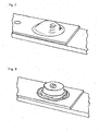
- FIG. 7 shows a by means of the melt pressure during injection molding introduced into a metal bead.
- Fig. 8 shows a schematic perspective view of a introduced by means of the melt pressure during injection molding in a metal bead, in which the injection-molded plastic has passed through a crack in material.
- Fig. 9 illustrates in schematic perspective view an incipient cracking, which was generated by a high melt pressure in injection molding.
- the Fig. 10 illustrates different variants of slot geometries, which can be introduced for the production of clinch connections in the sheet.
- the length, width and shape of the slots were varied to determine the influence of slot geometry on sheet metal forming and the resulting mechanical strengths of the clinch connection.
- the standard geometry was the vertical slot (perpendicular to the test load) with 10 mm length and 0.5 mm width. The comparison of the strength of these variants is discussed with the results of the mechanical test. While the slot direction has no influence on the forming behavior, it could be improved with the Phillips by 2-3%.
- the variation of the slot length and width gave the following results: With a large slot width, the achievable deformation is reduced, and the clinch connection resembles a riveted joint. The length of the sheet has little influence on the forming.
- the pressure detection in the forming zone of the light metal sheet plays an important role.
- a pressure sensor was placed in each case before and after the forming cavity.
- a temperature sensor was introduced in the tool to measure the sheet temperature during forming.
- the pressure was varied as a reprint by setting the switching point so that no re-forming took place without reprinting.
- the pressure was gradually increased by 50 of the 100 bar until it came to the breaking of the sheet.
- the max. Forming (u) and the forming radius (r) set in relation to each other.
- FIG. 11 illustrates the relationship between maximum deformation u and the forming radius r at a dome-shaped bead (left diagram) or a roof-shaped bead (right diagram).
- the schematic diagram of Fig. 12 illustrates the forming behavior of aluminum and magnesium when introducing beads or when clinching the sheets.
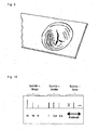
- FIG. 13 The sectional view of the Fig. 13 illustrates a cavity of different diameters (5 mm, 10 mm, 20 mm) and different depths (4 ... 8 mm), which could also have different edge radii (2 ... 6 mm). The results are discussed below.
- Sheet metal characterization has shown that elevated temperature forming could be improved so that a positive contribution to forming can be expected from the melt temperature present in the injection molding process, as shown by the graph of the Fig. 14 is clarified.
- Fig. 15 illustrates this relationship, which shows a more or less strong influence of the selected preheat temperature on the achievable forming ratio (u / r).
- the melt temperature may have an indirect influence on its formability by heating the sheet.
- the diameter of the Umformkavtician is important. Three different 10, 20 and 30 mm forming cavities were used. In the production of beads could be achieved at the same pressure with a larger Umformkavtician a larger deformation. When using a small diameter of Umformkavtician the necessary pressure for a breakage of the sheet could be significantly increased. Since carrying hybrid components usually can have larger forming zones than in the present studies, larger transformations at lower pressures can be achieved. It could be shown that the clinch forming shows only a small dependence on the forming diameter.
- the diagram of Fig. 16 illustrates the relationship between forming diameter (0 ... 30 mm) and the achievable forming ratio (u / r) at various injection pressures (100 bar, 400 bar), in each case for magnesium and aluminum.
- Another parameter is formed by the edge radius of the Umformkavtician. While the standard geometry of the trials was a 20 mm diameter with R2 edge radius, a larger radius of R6 was also used. As a result, the stress in the forming zone can be reduced, whereby a greater pressure can be applied, which leads to a larger deformation. With the edge radius of R6, a significant improvement in the forming could be achieved over the entire pressure range used. In comparison to the radius R2, the maximum deformation (fracture) of aluminum sheet was increased from 48% to 87% and for magnesium sheet from 31% to 77%. Thus, a suitable forming geometry for achieving a desired deformation of the light metal sheet of great importance.
- Fig. 18 illustrates the relationship between injection pressure, forming ratio and edge radius. It can be seen that the achievable forming ratio also increases with a given injection pressure with a larger edge radius.
- the standard sheet thickness was 1.5 mm for magnesium and aluminum, the latter also being used with 1 and 2 mm. All sheet thicknesses could be reshaped well, but the pressure requirement was very different.
- the forming behavior of magnesium and aluminum sheet as well as the bond strength of the clinch joint are measured and compared with the conventional rivet composite.
- the geometry of the clinch slot also influences the strength of the connection with the forming behavior.
- a test plan for the local forming of sheet metal was carried out. Forming behavior, geometry, clinching, load capacity and process control were compared.
- the strength could be increased by increasing the diameter of the forming cavity, although the slot dimensions were 10 x 0.5 mm in all three cases. This is because with increasing the diameter of a larger deformation (similar to a bead) takes place, which can accommodate higher forces in the test direction.
- the area for forming an additional adhesive bond in the forming cavity also increases.
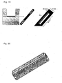
- FIGS. 19 to 22 show, the Fig. 19 in schematic representations of the process of introducing longitudinal beads in a U-shaped support member from which a hybrid component is made.
- longitudinal beads are introduced into the base area in a carrier component by the melt pressure.
- the aim of this change is to improve the resistance of the wearer to bending loads.
- the longitudinal beads may, for example, have a length of about 90 mm, a width of about 10 mm, a depth of up to about 4 mm and an edge radius of about 4 mm.
- FIG. 20 shows the finished shaped support member accordingly Fig. 19 , which is additionally provided with a series of clinch connections.
- the longitudinal beads and the clinch connections in the bottom region of the carrier can be integrated, for example, by simple, replaceable strips in the bottom of a nozzle-side mold insert.
- the strips may preferably be exchangeable from the front.
- the connecting elements for attaching the strips should not be in areas of the laterlyformenden rib structure in order to avoid unwanted deterioration of the component surfaces.
- FIG. 21 show in the process of introducing Clinchtagenen in a U-shaped support member from which a hybrid component according to the invention is made.
- the clinch connections can optionally be aligned with each other or slightly offset from one another.
- the clinch composites can be reminiscent of the execution of conventional rivet joints in order to ensure a comparability of different form-fitting composites.
- the clinch openings may, for example, each have a diameter of about 12 mm, a depth of up to about 4 mm and an edge radius of about 4 mm.
- diagonal beads can furthermore be embossed on the flanks of such a carrier component.
- the perspective part of the Fig. 22 illustrates a diagonal bead, which is in a flank of a U-shaped Carrier component accordingly Fig. 21 is introduced.
- a frame in the new nozzle-side tool insert is provided, which should enable the demoulding of the resulting diagonal beads undercuts in the component.
- hybrid synergies exploit material synergies.
- process-related, material and constructive aspects must be equally considered.
- Good matching allows lightweight structural components with good mechanical properties.
- the design of the positive and / or material-locking connections between the components occupies a central position.
- form-fitting connections are formed.
- the design of plastic ribs should aim at a local and load-dependent reinforcement of the metal insert part, so that e.g. At bending loads buckling of Einlegeteilflanken can be prevented. In the case of a torsional load with diagonal ribs a parallel displacement of Einlegeteilflanken is prevented.
Claims (19)
- Produit semi-fini plat déformé comportant au moins une garniture de renforcement en métal ou en matériau synthétique, qui est au moins en partie encastrée par liaison par forme dans une matière synthétique moulée par injection, caractérisé en ce que la garniture de renforcement présente au moins une zone, qui est déformée tout d'abord et durablement par la pression de fusion de la matière synthétique traitée selon un procédé de moulage par injection.
- Produit semi-fini selon la revendication 1, caractérisé en ce que la garniture de renforcement est constituée en tôle métallique.
- Produit semi-fini selon la revendication 1, caractérisé en ce que la garniture de renforcement est constituée en matière plastique, en particulier en matière plastique renforcée par des fibres.
- Produit semi-fini selon l'une quelconque des revendications 1 à 3, caractérisé en ce que la zone déformée par pression de fusion de la matière synthétique moulée par injection de la garniture est une déformation plastique.
- Produit semi-fini selon l'une quelconque des revendications précédentes, caractérisé en ce que la zone déformée de la garniture est ajourée au moins par endroits.
- Produit semi-fini selon la revendication 5, caractérisé en ce que la zone déformée de la garniture présente au moins une rupture ou une fissure par cisaillement.
- Produit semi-fini selon la revendication 5 ou la revendication 6, caractérisé en ce que la garniture dans la zone déformée présente au moins une nervure ou une ouverture préformée, en particulier une fente ou plusieurs fentes.
- Produit semi-fini selon la revendication 7, caractérisé en ce que dans la zone déformée par pression de fusion de la matière synthétique moulée par injection l'au moins une ouverture ou fente est évasée et/ou au agrandie dans au moins une zone de bord.
- Produit semi-fini selon l'une quelconque des revendications précédentes, caractérisé en ce que la zone déformée par pression de fusion de la matière synthétique moulée par injection de la garniture est entièrement entourée par une matière synthétique moulée par injection ou est encastrée dans celle-ci.
- Produit semi-fini selon l'une quelconque des revendications 1 à 9, caractérisé en ce que une structure composite ou un composant hybride est formé(e) à partir d'au moins deux matériaux qui sont reliées l'un à l'autre par liaison de forme.
- Procédé de fabrication d'un produit semi-fini plat ou une structure composite comportant au moins une garniture de renforcement en métal ou en matériau synthétique, qui est injectée selon le procédé de moulage par injection au moins en partie par liaison par forme avec une matière synthétique, caractérisé en ce que la garniture de renforcement est déformée durablement au moins dans une zone par la pression de fusion de la matière synthétique traitée selon un procédé de moulage par injection.
- Produit semi-fini selon la revendication 11, caractérisé en ce que la zone déformée par pression de fusion de la matière synthétique moulée par injection de la garniture est déformée plastiquement.
- Procédé selon la revendication 11 ou 12, caractérisé en ce que la zone déformée de la garniture est ajourée par pression de fusion de la matière synthétique au moins par endroits.
- Produit semi-fini selon la revendication 13, caractérisé en ce que la zone déformée de la garniture subit pendant le processus de moulage par pression au moins une rupture ou une fente par cisaillement.
- Produit semi-fini selon la revendication 13 ou la revendication 14, caractérisé en ce que avant le moulage par injection, la garniture dans la zone à déformer par injection est pourvue d'au moins une nervure préformée ou une ouverture préformée, en particulier une fente ou plusieurs fentes.
- Procédé selon la revendication 15, caractérisé en ce que dans la zone déformée par pression de fusion de la matière synthétique moulée par injection l'au moins une ouverture ou fente est évasée et/ou au agrandie dans au moins une zone de bord.
- Procédé selon l'une quelconque des revendications 11 à 16, caractérisé en ce que la zone déformée par pression de fusion de la matière synthétique moulée par injection de la garniture est entièrement entourée par une matière synthétique moulée par injection ou est encastrée dans celle-ci.
- Procédé selon l'une quelconque des revendications 11 à 17, caractérisé en ce qu'une tôle métallique utilisée en tant que garniture est en outre chauffée avant ou pendant le moulage par injection.
- Procédé selon la revendication 18, caractérisé en ce que la tôle métallique est chauffée au moyen d'un équilibrage de la température de l'outil.
Applications Claiming Priority (3)
| Application Number | Priority Date | Filing Date | Title |
|---|---|---|---|
| DE102005053357 | 2005-11-07 | ||
| DE102005061280A DE102005061280B3 (de) | 2005-11-07 | 2005-12-20 | Umgeformtes flächiges Halbzeug, Struktur- bzw. Hybridbauteil und Verfahren zur Herstellung eines derartigen Halbzeugs bzw. Bauteils |
| PCT/EP2006/010657 WO2007051652A1 (fr) | 2005-11-07 | 2006-11-07 | Produit semi-fini plat conformé, composant structurel ou hybride et procédé de fabrication d’un tel produit semi-fini ou d’un tel composant |
Publications (2)
| Publication Number | Publication Date |
|---|---|
| EP1945446A1 EP1945446A1 (fr) | 2008-07-23 |
| EP1945446B1 true EP1945446B1 (fr) | 2015-08-19 |
Family
ID=37749337
Family Applications (1)
| Application Number | Title | Priority Date | Filing Date |
|---|---|---|---|
| EP06818402.7A Active EP1945446B1 (fr) | 2005-11-07 | 2006-11-07 | Produit semi-fini plat conformé, composant structurel ou hybride et procédé de fabrication d'un tel produit semi-fini ou d'un tel composant |
Country Status (3)
| Country | Link |
|---|---|
| EP (1) | EP1945446B1 (fr) |
| DE (1) | DE102005061280B3 (fr) |
| WO (1) | WO2007051652A1 (fr) |
Cited By (1)
| Publication number | Priority date | Publication date | Assignee | Title |
|---|---|---|---|---|
| DE202020005395U1 (de) | 2020-12-21 | 2022-03-22 | Scherdel Marienberg Gmbh | Verbindungssystem zum Verbinden zweier Fertigbauteile |
Families Citing this family (15)
| Publication number | Priority date | Publication date | Assignee | Title |
|---|---|---|---|---|
| DE102007036660A1 (de) * | 2007-08-03 | 2009-02-05 | Kraussmaffei Technologies Gmbh | Verfahren und Vorrichtung zur Herstellung eines verstärkten Composite-Produktes |
| DE102007060628A1 (de) * | 2007-12-15 | 2009-06-18 | Daimler Ag | Verfahren zur Herstellung von Verbundbauteilen |
| FR2928100B1 (fr) * | 2008-02-28 | 2010-04-02 | Plastic Omnium Cie | Procede de fabrication d'une piece structurelle de vehicule automobile et une telle piece. |
| EP2528962A1 (fr) | 2010-01-27 | 2012-12-05 | Dow Global Technologies LLC | Catalyseur de polyuréthane à action retardée |
| DE102010015426A1 (de) * | 2010-04-19 | 2011-10-20 | Audi Ag | Verfahren zum Herstellen eines Verbundbauteils |
| DE102010055074A1 (de) | 2010-12-18 | 2012-06-21 | Daimler Ag | Umformvorrichtung zum Umformen eines Halbzeugs, insbesondere eines textilen Halbzeugs, sowie Verfahren zum Umformen eines solchen Halbzeugs |
| DE102011009727A1 (de) | 2011-01-29 | 2012-01-19 | Daimler Ag | Verfahren zum Herstellen eines Verbundbauteils sowie Vorrichtung zum Herstellen eines Verbundbauteils |
| DE102012012746A1 (de) | 2012-06-27 | 2014-01-02 | Daimler Ag | Stirnwandmodul in Hybridbauweise für einen Kraftwagen |
| CA2905266C (fr) | 2013-03-13 | 2019-09-24 | Aisin Takaoka Co., Ltd. | Structure composite composee d'une feuille plastique renforcee de fibres et d'une feuille metallique et procede permettant de fabriquer cette structure composite |
| DE102013205745A1 (de) * | 2013-04-02 | 2014-10-02 | Bayerische Motoren Werke Aktiengesellschaft | Verfahren zur Herstellung einer Baugruppe sowie Baugruppe |
| CN104819438A (zh) * | 2015-04-23 | 2015-08-05 | 合肥京东方显示光源有限公司 | 背板、胶铁一体结构、背光模组和显示装置 |
| DE102016202087A1 (de) * | 2016-02-11 | 2017-08-17 | Volkswagen Aktiengesellschaft | Verfahren zur Herstellung eines Verbundbauteils sowie ein dieses Verbundbauteil aufweisendes Fahrzeug |
| JP7197863B2 (ja) * | 2019-06-17 | 2022-12-28 | 株式会社神戸製鋼所 | 固相拡散接合方法 |
| JP7184730B2 (ja) * | 2019-10-28 | 2022-12-06 | 株式会社神戸製鋼所 | アルミニウム材の接合方法 |
| CN114007798B (zh) * | 2019-06-17 | 2023-03-24 | 株式会社神户制钢所 | 铝材的接合方法 |
Family Cites Families (3)
| Publication number | Priority date | Publication date | Assignee | Title |
|---|---|---|---|---|
| DE3839855A1 (de) * | 1988-11-25 | 1990-05-31 | Bayer Ag | Leichtbauteil |
| DE4409081C1 (de) * | 1994-03-17 | 1995-04-20 | Daimler Benz Ag | Baueinheit für den Stirnwand- und Cockpitbereich eines Personenkraftwagens |
| DE19916619C2 (de) * | 1999-04-13 | 2001-11-22 | Schade Plettenberg Glasmodule | Zusammengesetztes Bauteil |
-
2005
- 2005-12-20 DE DE102005061280A patent/DE102005061280B3/de not_active Expired - Fee Related
-
2006
- 2006-11-07 WO PCT/EP2006/010657 patent/WO2007051652A1/fr active Application Filing
- 2006-11-07 EP EP06818402.7A patent/EP1945446B1/fr active Active
Cited By (1)
| Publication number | Priority date | Publication date | Assignee | Title |
|---|---|---|---|---|
| DE202020005395U1 (de) | 2020-12-21 | 2022-03-22 | Scherdel Marienberg Gmbh | Verbindungssystem zum Verbinden zweier Fertigbauteile |
Also Published As
| Publication number | Publication date |
|---|---|
| DE102005061280B3 (de) | 2007-04-12 |
| WO2007051652A1 (fr) | 2007-05-10 |
| EP1945446A1 (fr) | 2008-07-23 |
Similar Documents
| Publication | Publication Date | Title |
|---|---|---|
| EP1945446B1 (fr) | Produit semi-fini plat conformé, composant structurel ou hybride et procédé de fabrication d'un tel produit semi-fini ou d'un tel composant | |
| EP2990308B1 (fr) | Support d'essieu pour un vehicule automobile et procede destine a la fabrication d'un support d'essieu | |
| DE102009040901B4 (de) | Verfahren zum Herstellen von Tragstrukturen in Kraftfahrzeugen | |
| DE10301520B4 (de) | Kunststoff-Metall-Verbundbauteil | |
| EP3040182B1 (fr) | Procede de fabrication d'un composant structural, demi-produit, procede de fabrication d'un demi-produit, composant structural et vehicules aeronautiques ou spatiaux | |
| DE102009042272B4 (de) | Leichtbauteil, Verfahren zum Herstellen eines Leichtbauteils und Kraftfahrzeug mit einem Leichtbauteil | |
| DE102012213050A1 (de) | Leichtgewichtige Fahrzeugräder mit Karbonfasereinsätzen | |
| DE10106458A1 (de) | Verfahren zur Herstellung von Verbundteilen durch Mehrkomponentenspritzguss | |
| DE102015206534B4 (de) | Verbindungsanordnung sowie Verfahren zur Herstellung einer solchen Verbindungsanordnung | |
| EP2780155B1 (fr) | Procédé de fabrication d'un élément structurel, dispositif permettant de mettre en uvre le procédé et élément structurel | |
| EP2955237A1 (fr) | Procédé de fabrication d'un élément de véhicule automobile en aluminium | |
| DE102016106688A1 (de) | Hybridbauteil für ein Fahrzeug | |
| DE19912618C2 (de) | Bauteil mit partieller Verstärkung und Verfahren zu dessen Herstellung | |
| DE102016011304A1 (de) | Sitzstrukturelement für einen Kraftfahrzeugsitz, Verfahren zu dessen Herstellung und Kraftfahrzeugsitz mit solchem Sitzstrukturelement | |
| DE10339350A1 (de) | Verfahren zum Umformen von Blechen | |
| DE102005050963A1 (de) | Bauteil und Verfahren zum Herstellen eines Bauteils | |
| EP2963140B1 (fr) | Procédé de fabrication d'un élément de véhicule automobile en aluminium | |
| WO2009062560A1 (fr) | Elément composite et procédé pour fabriquer un élément composite | |
| WO2011095536A1 (fr) | Procédé de fabrication d'un élément de revêtement d'un véhicule, dispositif correspondant ainsi qu'élément de revêtement | |
| DE102014205896A1 (de) | Verfahren zur Herstellung eines Bauteils aus Organoblech und Werkzeug | |
| EP3909864A1 (fr) | Procédé de fabrication d'un composant de structure d'un véhicule, en particulier un aéronef ou un véhicule spatial | |
| DE10338109B4 (de) | Verfahren zur Herstellung eines Verbundbauteils | |
| DE102005060486B4 (de) | Verfahren zur Herstellung eines hochbelastbaren Verbundteils sowie ein danach hergestelltes hochbelastbares Verbundteil und Verwendung | |
| EP3778179A1 (fr) | Procédé et dispositif de fabrication d'un composant | |
| EP3096949B1 (fr) | Cadre d'accoudoir, accoudoir, et procédé de production d'un cadre d'accoudoir |
Legal Events
| Date | Code | Title | Description |
|---|---|---|---|
| PUAI | Public reference made under article 153(3) epc to a published international application that has entered the european phase |
Free format text: ORIGINAL CODE: 0009012 |
|
| 17P | Request for examination filed |
Effective date: 20080409 |
|
| AK | Designated contracting states |
Kind code of ref document: A1 Designated state(s): AT BE BG CH CY CZ DE DK EE ES FI FR GB GR HU IE IS IT LI LT LU LV MC NL PL PT RO SE SI SK TR |
|
| RIN1 | Information on inventor provided before grant (corrected) |
Inventor name: SCHMID, MICHAEL Inventor name: EHRENSTEIN, GOTTFRIED, W. Inventor name: MUELLER, NORBERT Inventor name: AL-SHEYYAB, AHMAD Inventor name: DREBINGER, LUDWIG |
|
| 17Q | First examination report despatched |
Effective date: 20080820 |
|
| DAX | Request for extension of the european patent (deleted) | ||
| RAP1 | Party data changed (applicant data changed or rights of an application transferred) |
Owner name: DAIMLER AG |
|
| GRAP | Despatch of communication of intention to grant a patent |
Free format text: ORIGINAL CODE: EPIDOSNIGR1 |
|
| INTG | Intention to grant announced |
Effective date: 20150313 |
|
| GRAS | Grant fee paid |
Free format text: ORIGINAL CODE: EPIDOSNIGR3 |
|
| GRAA | (expected) grant |
Free format text: ORIGINAL CODE: 0009210 |
|
| AK | Designated contracting states |
Kind code of ref document: B1 Designated state(s): AT BE BG CH CY CZ DE DK EE ES FI FR GB GR HU IE IS IT LI LT LU LV MC NL PL PT RO SE SI SK TR |
|
| REG | Reference to a national code |
Ref country code: GB Ref legal event code: FG4D Free format text: NOT ENGLISH |
|
| REG | Reference to a national code |
Ref country code: CH Ref legal event code: EP |
|
| REG | Reference to a national code |
Ref country code: IE Ref legal event code: FG4D Free format text: LANGUAGE OF EP DOCUMENT: GERMAN |
|
| REG | Reference to a national code |
Ref country code: AT Ref legal event code: REF Ref document number: 743494 Country of ref document: AT Kind code of ref document: T Effective date: 20150915 |
|
| REG | Reference to a national code |
Ref country code: DE Ref legal event code: R096 Ref document number: 502006014501 Country of ref document: DE |
|
| REG | Reference to a national code |
Ref country code: FR Ref legal event code: PLFP Year of fee payment: 10 |
|
| REG | Reference to a national code |
Ref country code: LT Ref legal event code: MG4D |
|
| REG | Reference to a national code |
Ref country code: NL Ref legal event code: MP Effective date: 20150819 |
|
| PG25 | Lapsed in a contracting state [announced via postgrant information from national office to epo] |
Ref country code: LT Free format text: LAPSE BECAUSE OF FAILURE TO SUBMIT A TRANSLATION OF THE DESCRIPTION OR TO PAY THE FEE WITHIN THE PRESCRIBED TIME-LIMIT Effective date: 20150819 Ref country code: GR Free format text: LAPSE BECAUSE OF FAILURE TO SUBMIT A TRANSLATION OF THE DESCRIPTION OR TO PAY THE FEE WITHIN THE PRESCRIBED TIME-LIMIT Effective date: 20151120 Ref country code: LV Free format text: LAPSE BECAUSE OF FAILURE TO SUBMIT A TRANSLATION OF THE DESCRIPTION OR TO PAY THE FEE WITHIN THE PRESCRIBED TIME-LIMIT Effective date: 20150819 Ref country code: FI Free format text: LAPSE BECAUSE OF FAILURE TO SUBMIT A TRANSLATION OF THE DESCRIPTION OR TO PAY THE FEE WITHIN THE PRESCRIBED TIME-LIMIT Effective date: 20150819 |
|
| PG25 | Lapsed in a contracting state [announced via postgrant information from national office to epo] |
Ref country code: PT Free format text: LAPSE BECAUSE OF FAILURE TO SUBMIT A TRANSLATION OF THE DESCRIPTION OR TO PAY THE FEE WITHIN THE PRESCRIBED TIME-LIMIT Effective date: 20151221 Ref country code: ES Free format text: LAPSE BECAUSE OF FAILURE TO SUBMIT A TRANSLATION OF THE DESCRIPTION OR TO PAY THE FEE WITHIN THE PRESCRIBED TIME-LIMIT Effective date: 20150819 Ref country code: PL Free format text: LAPSE BECAUSE OF FAILURE TO SUBMIT A TRANSLATION OF THE DESCRIPTION OR TO PAY THE FEE WITHIN THE PRESCRIBED TIME-LIMIT Effective date: 20150819 Ref country code: IS Free format text: LAPSE BECAUSE OF FAILURE TO SUBMIT A TRANSLATION OF THE DESCRIPTION OR TO PAY THE FEE WITHIN THE PRESCRIBED TIME-LIMIT Effective date: 20151219 Ref country code: SE Free format text: LAPSE BECAUSE OF FAILURE TO SUBMIT A TRANSLATION OF THE DESCRIPTION OR TO PAY THE FEE WITHIN THE PRESCRIBED TIME-LIMIT Effective date: 20150819 |
|
| PG25 | Lapsed in a contracting state [announced via postgrant information from national office to epo] |
Ref country code: NL Free format text: LAPSE BECAUSE OF FAILURE TO SUBMIT A TRANSLATION OF THE DESCRIPTION OR TO PAY THE FEE WITHIN THE PRESCRIBED TIME-LIMIT Effective date: 20150819 |
|
| PG25 | Lapsed in a contracting state [announced via postgrant information from national office to epo] |
Ref country code: SK Free format text: LAPSE BECAUSE OF FAILURE TO SUBMIT A TRANSLATION OF THE DESCRIPTION OR TO PAY THE FEE WITHIN THE PRESCRIBED TIME-LIMIT Effective date: 20150819 Ref country code: CZ Free format text: LAPSE BECAUSE OF FAILURE TO SUBMIT A TRANSLATION OF THE DESCRIPTION OR TO PAY THE FEE WITHIN THE PRESCRIBED TIME-LIMIT Effective date: 20150819 Ref country code: DK Free format text: LAPSE BECAUSE OF FAILURE TO SUBMIT A TRANSLATION OF THE DESCRIPTION OR TO PAY THE FEE WITHIN THE PRESCRIBED TIME-LIMIT Effective date: 20150819 Ref country code: EE Free format text: LAPSE BECAUSE OF FAILURE TO SUBMIT A TRANSLATION OF THE DESCRIPTION OR TO PAY THE FEE WITHIN THE PRESCRIBED TIME-LIMIT Effective date: 20150819 Ref country code: IT Free format text: LAPSE BECAUSE OF FAILURE TO SUBMIT A TRANSLATION OF THE DESCRIPTION OR TO PAY THE FEE WITHIN THE PRESCRIBED TIME-LIMIT Effective date: 20150819 |
|
| REG | Reference to a national code |
Ref country code: DE Ref legal event code: R097 Ref document number: 502006014501 Country of ref document: DE |
|
| PG25 | Lapsed in a contracting state [announced via postgrant information from national office to epo] |
Ref country code: RO Free format text: LAPSE BECAUSE OF FAILURE TO SUBMIT A TRANSLATION OF THE DESCRIPTION OR TO PAY THE FEE WITHIN THE PRESCRIBED TIME-LIMIT Effective date: 20150819 |
|
| PLBE | No opposition filed within time limit |
Free format text: ORIGINAL CODE: 0009261 |
|
| STAA | Information on the status of an ep patent application or granted ep patent |
Free format text: STATUS: NO OPPOSITION FILED WITHIN TIME LIMIT |
|
| PG25 | Lapsed in a contracting state [announced via postgrant information from national office to epo] |
Ref country code: MC Free format text: LAPSE BECAUSE OF FAILURE TO SUBMIT A TRANSLATION OF THE DESCRIPTION OR TO PAY THE FEE WITHIN THE PRESCRIBED TIME-LIMIT Effective date: 20150819 Ref country code: LU Free format text: LAPSE BECAUSE OF FAILURE TO SUBMIT A TRANSLATION OF THE DESCRIPTION OR TO PAY THE FEE WITHIN THE PRESCRIBED TIME-LIMIT Effective date: 20151107 |
|
| REG | Reference to a national code |
Ref country code: CH Ref legal event code: PL |
|
| 26N | No opposition filed |
Effective date: 20160520 |
|
| GBPC | Gb: european patent ceased through non-payment of renewal fee |
Effective date: 20151119 |
|
| PG25 | Lapsed in a contracting state [announced via postgrant information from national office to epo] |
Ref country code: LI Free format text: LAPSE BECAUSE OF NON-PAYMENT OF DUE FEES Effective date: 20151130 Ref country code: CH Free format text: LAPSE BECAUSE OF NON-PAYMENT OF DUE FEES Effective date: 20151130 |
|
| REG | Reference to a national code |
Ref country code: IE Ref legal event code: MM4A |
|
| PG25 | Lapsed in a contracting state [announced via postgrant information from national office to epo] |
Ref country code: SI Free format text: LAPSE BECAUSE OF FAILURE TO SUBMIT A TRANSLATION OF THE DESCRIPTION OR TO PAY THE FEE WITHIN THE PRESCRIBED TIME-LIMIT Effective date: 20150819 |
|
| PG25 | Lapsed in a contracting state [announced via postgrant information from national office to epo] |
Ref country code: GB Free format text: LAPSE BECAUSE OF NON-PAYMENT OF DUE FEES Effective date: 20151119 Ref country code: IE Free format text: LAPSE BECAUSE OF NON-PAYMENT OF DUE FEES Effective date: 20151107 |
|
| REG | Reference to a national code |
Ref country code: FR Ref legal event code: PLFP Year of fee payment: 11 |
|
| REG | Reference to a national code |
Ref country code: AT Ref legal event code: MM01 Ref document number: 743494 Country of ref document: AT Kind code of ref document: T Effective date: 20151107 |
|
| PG25 | Lapsed in a contracting state [announced via postgrant information from national office to epo] |
Ref country code: AT Free format text: LAPSE BECAUSE OF NON-PAYMENT OF DUE FEES Effective date: 20151107 |
|
| PG25 | Lapsed in a contracting state [announced via postgrant information from national office to epo] |
Ref country code: HU Free format text: LAPSE BECAUSE OF FAILURE TO SUBMIT A TRANSLATION OF THE DESCRIPTION OR TO PAY THE FEE WITHIN THE PRESCRIBED TIME-LIMIT; INVALID AB INITIO Effective date: 20061107 Ref country code: BG Free format text: LAPSE BECAUSE OF FAILURE TO SUBMIT A TRANSLATION OF THE DESCRIPTION OR TO PAY THE FEE WITHIN THE PRESCRIBED TIME-LIMIT Effective date: 20150819 |
|
| PG25 | Lapsed in a contracting state [announced via postgrant information from national office to epo] |
Ref country code: CY Free format text: LAPSE BECAUSE OF FAILURE TO SUBMIT A TRANSLATION OF THE DESCRIPTION OR TO PAY THE FEE WITHIN THE PRESCRIBED TIME-LIMIT Effective date: 20150819 |
|
| PG25 | Lapsed in a contracting state [announced via postgrant information from national office to epo] |
Ref country code: BE Free format text: LAPSE BECAUSE OF NON-PAYMENT OF DUE FEES Effective date: 20151130 |
|
| PG25 | Lapsed in a contracting state [announced via postgrant information from national office to epo] |
Ref country code: TR Free format text: LAPSE BECAUSE OF FAILURE TO SUBMIT A TRANSLATION OF THE DESCRIPTION OR TO PAY THE FEE WITHIN THE PRESCRIBED TIME-LIMIT Effective date: 20150819 |
|
| REG | Reference to a national code |
Ref country code: FR Ref legal event code: PLFP Year of fee payment: 12 |
|
| REG | Reference to a national code |
Ref country code: DE Ref legal event code: R081 Ref document number: 502006014501 Country of ref document: DE Owner name: MERCEDES-BENZ GROUP AG, DE Free format text: FORMER OWNER: DAIMLER AG, 70327 STUTTGART, DE Ref country code: DE Ref legal event code: R082 Ref document number: 502006014501 Country of ref document: DE Representative=s name: JENSEN & SON, GB Ref country code: DE Ref legal event code: R081 Ref document number: 502006014501 Country of ref document: DE Owner name: DAIMLER AG, DE Free format text: FORMER OWNER: DAIMLER AG, 70327 STUTTGART, DE Ref country code: DE Ref legal event code: R082 Ref document number: 502006014501 Country of ref document: DE Representative=s name: JENSENS IP LIMITED, IE |
|
| REG | Reference to a national code |
Ref country code: DE Ref legal event code: R082 Ref document number: 502006014501 Country of ref document: DE Ref country code: DE Ref legal event code: R082 Ref document number: 502006014501 Country of ref document: DE Representative=s name: JENSENS IP LIMITED, IE |
|
| REG | Reference to a national code |
Ref country code: DE Ref legal event code: R081 Ref document number: 502006014501 Country of ref document: DE Owner name: MERCEDES-BENZ GROUP AG, DE Free format text: FORMER OWNER: DAIMLER AG, STUTTGART, DE Ref country code: DE Ref legal event code: R082 Ref document number: 502006014501 Country of ref document: DE |
|
| REG | Reference to a national code |
Ref country code: DE Ref legal event code: R084 Ref document number: 502006014501 Country of ref document: DE |
|
| PGFP | Annual fee paid to national office [announced via postgrant information from national office to epo] |
Ref country code: FR Payment date: 20231123 Year of fee payment: 18 Ref country code: DE Payment date: 20231127 Year of fee payment: 18 |