EP1945446B1 - Shaped two-dimensional semifinished part, structured or hybrid component and method for producing such a semifinished part or component - Google Patents
Shaped two-dimensional semifinished part, structured or hybrid component and method for producing such a semifinished part or component Download PDFInfo
- Publication number
- EP1945446B1 EP1945446B1 EP06818402.7A EP06818402A EP1945446B1 EP 1945446 B1 EP1945446 B1 EP 1945446B1 EP 06818402 A EP06818402 A EP 06818402A EP 1945446 B1 EP1945446 B1 EP 1945446B1
- Authority
- EP
- European Patent Office
- Prior art keywords
- insert
- injection
- deformed
- plastic
- region
- Prior art date
- Legal status (The legal status is an assumption and is not a legal conclusion. Google has not performed a legal analysis and makes no representation as to the accuracy of the status listed.)
- Active
Links
- 238000004519 manufacturing process Methods 0.000 title claims description 44
- 229910052751 metal Inorganic materials 0.000 claims description 84
- 239000002184 metal Substances 0.000 claims description 84
- 238000000034 method Methods 0.000 claims description 48
- 239000011324 bead Substances 0.000 claims description 42
- 239000004033 plastic Substances 0.000 claims description 41
- 229920003023 plastic Polymers 0.000 claims description 41
- 239000000155 melt Substances 0.000 claims description 35
- 238000001746 injection moulding Methods 0.000 claims description 32
- 239000002991 molded plastic Substances 0.000 claims description 31
- 239000002131 composite material Substances 0.000 claims description 26
- 239000000463 material Substances 0.000 claims description 25
- 239000011265 semifinished product Substances 0.000 claims description 20
- 230000003014 reinforcing effect Effects 0.000 claims description 10
- 229920002430 Fibre-reinforced plastic Polymers 0.000 claims 1
- 239000011151 fibre-reinforced plastic Substances 0.000 claims 1
- 230000008569 process Effects 0.000 description 24
- FYYHWMGAXLPEAU-UHFFFAOYSA-N Magnesium Chemical compound [Mg] FYYHWMGAXLPEAU-UHFFFAOYSA-N 0.000 description 21
- XAGFODPZIPBFFR-UHFFFAOYSA-N aluminium Chemical compound [Al] XAGFODPZIPBFFR-UHFFFAOYSA-N 0.000 description 21
- 238000002347 injection Methods 0.000 description 21
- 239000007924 injection Substances 0.000 description 21
- 229910052782 aluminium Inorganic materials 0.000 description 20
- 238000010586 diagram Methods 0.000 description 20
- 239000011777 magnesium Substances 0.000 description 16
- 229910052749 magnesium Inorganic materials 0.000 description 16
- 238000013461 design Methods 0.000 description 15
- 230000010354 integration Effects 0.000 description 10
- 238000010276 construction Methods 0.000 description 8
- 238000005516 engineering process Methods 0.000 description 7
- 238000000465 moulding Methods 0.000 description 7
- 238000012360 testing method Methods 0.000 description 7
- 229910000831 Steel Inorganic materials 0.000 description 6
- 238000004886 process control Methods 0.000 description 6
- 239000010959 steel Substances 0.000 description 6
- 230000008901 benefit Effects 0.000 description 5
- 150000001875 compounds Chemical class 0.000 description 5
- 230000001419 dependent effect Effects 0.000 description 3
- 238000007781 pre-processing Methods 0.000 description 3
- 238000012545 processing Methods 0.000 description 3
- 229920001169 thermoplastic Polymers 0.000 description 3
- 239000004416 thermosoftening plastic Substances 0.000 description 3
- 229920010540 PA6 GF30 Polymers 0.000 description 2
- 229920006920 PA6-GF30 Polymers 0.000 description 2
- 238000004026 adhesive bonding Methods 0.000 description 2
- 238000004873 anchoring Methods 0.000 description 2
- 238000005452 bending Methods 0.000 description 2
- 238000005336 cracking Methods 0.000 description 2
- 238000011161 development Methods 0.000 description 2
- 230000018109 developmental process Effects 0.000 description 2
- 238000009826 distribution Methods 0.000 description 2
- 230000008030 elimination Effects 0.000 description 2
- 238000003379 elimination reaction Methods 0.000 description 2
- 238000010438 heat treatment Methods 0.000 description 2
- 230000000977 initiatory effect Effects 0.000 description 2
- 238000005304 joining Methods 0.000 description 2
- 239000007788 liquid Substances 0.000 description 2
- 150000002739 metals Chemical class 0.000 description 2
- 238000002360 preparation method Methods 0.000 description 2
- 230000009467 reduction Effects 0.000 description 2
- 230000002787 reinforcement Effects 0.000 description 2
- 238000004904 shortening Methods 0.000 description 2
- 229910000838 Al alloy Inorganic materials 0.000 description 1
- 229910000861 Mg alloy Inorganic materials 0.000 description 1
- 239000000853 adhesive Substances 0.000 description 1
- 230000001070 adhesive effect Effects 0.000 description 1
- 230000015572 biosynthetic process Effects 0.000 description 1
- 238000009529 body temperature measurement Methods 0.000 description 1
- 239000004918 carbon fiber reinforced polymer Substances 0.000 description 1
- 239000000969 carrier Substances 0.000 description 1
- 230000008859 change Effects 0.000 description 1
- 238000012512 characterization method Methods 0.000 description 1
- 230000001427 coherent effect Effects 0.000 description 1
- 238000007796 conventional method Methods 0.000 description 1
- 230000007423 decrease Effects 0.000 description 1
- 238000001514 detection method Methods 0.000 description 1
- 230000006866 deterioration Effects 0.000 description 1
- 238000006073 displacement reaction Methods 0.000 description 1
- 239000013013 elastic material Substances 0.000 description 1
- 238000002474 experimental method Methods 0.000 description 1
- 239000011152 fibreglass Substances 0.000 description 1
- 230000006872 improvement Effects 0.000 description 1
- 238000007373 indentation Methods 0.000 description 1
- 238000012986 modification Methods 0.000 description 1
- 230000004048 modification Effects 0.000 description 1
- 230000008450 motivation Effects 0.000 description 1
- 238000005457 optimization Methods 0.000 description 1
- 239000002985 plastic film Substances 0.000 description 1
- 229920000642 polymer Polymers 0.000 description 1
- 238000007493 shaping process Methods 0.000 description 1
- 230000003068 static effect Effects 0.000 description 1
- 239000000126 substance Substances 0.000 description 1
- 230000009466 transformation Effects 0.000 description 1
- 238000000844 transformation Methods 0.000 description 1
Images


Classifications
-
- B—PERFORMING OPERATIONS; TRANSPORTING
- B29—WORKING OF PLASTICS; WORKING OF SUBSTANCES IN A PLASTIC STATE IN GENERAL
- B29C—SHAPING OR JOINING OF PLASTICS; SHAPING OF MATERIAL IN A PLASTIC STATE, NOT OTHERWISE PROVIDED FOR; AFTER-TREATMENT OF THE SHAPED PRODUCTS, e.g. REPAIRING
- B29C45/00—Injection moulding, i.e. forcing the required volume of moulding material through a nozzle into a closed mould; Apparatus therefor
- B29C45/14—Injection moulding, i.e. forcing the required volume of moulding material through a nozzle into a closed mould; Apparatus therefor incorporating preformed parts or layers, e.g. injection moulding around inserts or for coating articles
- B29C45/1418—Injection moulding, i.e. forcing the required volume of moulding material through a nozzle into a closed mould; Apparatus therefor incorporating preformed parts or layers, e.g. injection moulding around inserts or for coating articles the inserts being deformed or preformed, e.g. by the injection pressure
-
- B—PERFORMING OPERATIONS; TRANSPORTING
- B29—WORKING OF PLASTICS; WORKING OF SUBSTANCES IN A PLASTIC STATE IN GENERAL
- B29C—SHAPING OR JOINING OF PLASTICS; SHAPING OF MATERIAL IN A PLASTIC STATE, NOT OTHERWISE PROVIDED FOR; AFTER-TREATMENT OF THE SHAPED PRODUCTS, e.g. REPAIRING
- B29C45/00—Injection moulding, i.e. forcing the required volume of moulding material through a nozzle into a closed mould; Apparatus therefor
- B29C45/14—Injection moulding, i.e. forcing the required volume of moulding material through a nozzle into a closed mould; Apparatus therefor incorporating preformed parts or layers, e.g. injection moulding around inserts or for coating articles
- B29C45/14311—Injection moulding, i.e. forcing the required volume of moulding material through a nozzle into a closed mould; Apparatus therefor incorporating preformed parts or layers, e.g. injection moulding around inserts or for coating articles using means for bonding the coating to the articles
- B29C2045/14327—Injection moulding, i.e. forcing the required volume of moulding material through a nozzle into a closed mould; Apparatus therefor incorporating preformed parts or layers, e.g. injection moulding around inserts or for coating articles using means for bonding the coating to the articles anchoring by forcing the material to pass through a hole in the article
-
- B—PERFORMING OPERATIONS; TRANSPORTING
- B29—WORKING OF PLASTICS; WORKING OF SUBSTANCES IN A PLASTIC STATE IN GENERAL
- B29C—SHAPING OR JOINING OF PLASTICS; SHAPING OF MATERIAL IN A PLASTIC STATE, NOT OTHERWISE PROVIDED FOR; AFTER-TREATMENT OF THE SHAPED PRODUCTS, e.g. REPAIRING
- B29C45/00—Injection moulding, i.e. forcing the required volume of moulding material through a nozzle into a closed mould; Apparatus therefor
- B29C45/14—Injection moulding, i.e. forcing the required volume of moulding material through a nozzle into a closed mould; Apparatus therefor incorporating preformed parts or layers, e.g. injection moulding around inserts or for coating articles
- B29C2045/1486—Details, accessories and auxiliary operations
- B29C2045/14983—Bursting or breakthrough of the insert by the injection pressure
-
- B—PERFORMING OPERATIONS; TRANSPORTING
- B29—WORKING OF PLASTICS; WORKING OF SUBSTANCES IN A PLASTIC STATE IN GENERAL
- B29C—SHAPING OR JOINING OF PLASTICS; SHAPING OF MATERIAL IN A PLASTIC STATE, NOT OTHERWISE PROVIDED FOR; AFTER-TREATMENT OF THE SHAPED PRODUCTS, e.g. REPAIRING
- B29C37/00—Component parts, details, accessories or auxiliary operations, not covered by group B29C33/00 or B29C35/00
- B29C37/0078—Measures or configurations for obtaining anchoring effects in the contact areas between layers
- B29C37/0082—Mechanical anchoring
- B29C37/0085—Mechanical anchoring by means of openings in the layers
-
- B—PERFORMING OPERATIONS; TRANSPORTING
- B29—WORKING OF PLASTICS; WORKING OF SUBSTANCES IN A PLASTIC STATE IN GENERAL
- B29C—SHAPING OR JOINING OF PLASTICS; SHAPING OF MATERIAL IN A PLASTIC STATE, NOT OTHERWISE PROVIDED FOR; AFTER-TREATMENT OF THE SHAPED PRODUCTS, e.g. REPAIRING
- B29C45/00—Injection moulding, i.e. forcing the required volume of moulding material through a nozzle into a closed mould; Apparatus therefor
- B29C45/14—Injection moulding, i.e. forcing the required volume of moulding material through a nozzle into a closed mould; Apparatus therefor incorporating preformed parts or layers, e.g. injection moulding around inserts or for coating articles
- B29C45/14631—Coating reinforcements
-
- B—PERFORMING OPERATIONS; TRANSPORTING
- B29—WORKING OF PLASTICS; WORKING OF SUBSTANCES IN A PLASTIC STATE IN GENERAL
- B29K—INDEXING SCHEME ASSOCIATED WITH SUBCLASSES B29B, B29C OR B29D, RELATING TO MOULDING MATERIALS OR TO MATERIALS FOR MOULDS, REINFORCEMENTS, FILLERS OR PREFORMED PARTS, e.g. INSERTS
- B29K2705/00—Use of metals, their alloys or their compounds, for preformed parts, e.g. for inserts
- B29K2705/02—Aluminium
-
- B—PERFORMING OPERATIONS; TRANSPORTING
- B29—WORKING OF PLASTICS; WORKING OF SUBSTANCES IN A PLASTIC STATE IN GENERAL
- B29L—INDEXING SCHEME ASSOCIATED WITH SUBCLASS B29C, RELATING TO PARTICULAR ARTICLES
- B29L2031/00—Other particular articles
- B29L2031/30—Vehicles, e.g. ships or aircraft, or body parts thereof
- B29L2031/3002—Superstructures characterized by combining metal and plastics, i.e. hybrid parts
Definitions
- the invention relates to a shaped flat semifinished product, a structural or hybrid component and a method for producing such a semifinished product or component.
- hybrid components The mostly made of metal and plastic parts are commonly referred to as hybrid components and can be used for a variety of purposes due to their diverse constructive degrees of freedom, for example. As structural elements in vehicle or aircraft.
- the hybrid components have the particular advantage that specifically the advantages of different materials can be used and combined with each other.
- EP 0 370 342 B1 is known as a carrier in the motor vehicle lightweight component in hybrid design known, which has a metal shell-shaped body, in the interior reinforcing ribs are arranged.
- the reinforcing ribs are made of injected plastic and are connected to the metal body at several points by the plastic arranged in the metal part passes through openings and extends beyond the surfaces of the openings.
- the reinforcing ribs enforce to achieve a high rigidity and strength of the interior of the U-shaped metal body.
- the EP 0 672 576 B1 describes a einmontierbare in a vehicle body assembly for the front edge and cockpit area of a passenger car.
- the unit is formed in its supporting substance of two composite components, each consisting of deep-drawn sheet metal and molded plastic.
- the sheet metal parts are formed according to the occurring load and with holes, breakthroughs u.
- the molded plastic is shaped such that with him a stiffening the sheet metal parts ribbing and corresponding receptacles for various attachments are formed.
- the EP 1 044 866 B1 further describes a composite component having a shell-like upper part and a reinforcement part, which are connected to one another via discrete connection points, wherein these two parts consist of materials with different thermal expansion coefficients. In the area of the joints between the two parts profile elements made of elastic material are effective.
- a first object of the invention is to provide a hybrid component which has improved mechanical properties with ease of manufacture.
- a preformed or formed flat semi-finished product with the features of claim 1 comprises at least one stiffening insert made of metal or plastic, which is embedded at least partially positively in injection-molded plastic.
- the stiffening insert has at least one region which is permanently deformed primarily by the melt pressure of the plastic processed by the injection molding process.
- the stiffening insert may in particular consist of sheet metal, in which case the most diverse materials and sheet thicknesses may be used, depending on the required component strength and desired application.
- As a material for the metal sheet is particularly light metal such as aluminum or magnesium alloys.
- conventional steel sheet or high-strength steel sheets can also be used.
- the metal or plastic sheet is plastically deformed by the injection-molded plastic, that a bead, an eruption or the like is formed in the stiffening insert, which is positively connected to the molded plastic, so that a mechanically very resistant and individually adjustable in its strength properties Hybrid component is formed.
- the stiffening insert may, as mentioned, be formed in particular from sheet metal.
- stiffening insert is also plastic, in particular composite plastics such as fiberglass, CFRP or the like.
- An essential aspect of the invention is that a direct plastic deformation or a breaking point of the stiffening insert and the formation of a positive connection of a hybrid component by the melt pressure of the injection-molded plastic. In this way, a process integration can be achieved by the production of compounds directly in the tool with the elimination of the pre-work on the stiffening insert.
- melt pressure acts wherever liquid melt flows, which is the case during the injection phase.
- the melt pressure can still act in the so-called.
- Nachbuchphase when the liquid melt is placed under a (quasi) static pressure.
- a preferred embodiment of the invention provides that the deformed region of the insert is at least partially broken. This breaks or tears the sheet or the plastic insert by increasing the melt pressure, so that the injected plastic then flow through the fracture point into the Umformkavtician and can make the positive connection.
- the Umformkavtician and the process control it is possible to control the sheet metal breakage or breakage of the plastic insert. With the melt pressure, the insert can be transformed and / or broken, which allows the efficient production of beads and so-called clinch connections.
- both magnesium sheet and aluminum sheet can achieve degrees of deformation which can otherwise typically only be achieved with forming processes which require a separate processing step.
- various designs of the clinch connections are conceivable, which partly make do without a previous processing of the sheet.
- the insert may have in the deformed region at least one preformed bead or preformed opening, in particular one slot or a plurality of slots.
- at least one opening or slot is widened and / or widened in at least one edge area.
- the area of the insert which is deformed by the melt pressure of the injection-molded plastic is largely completely surrounded by the injection-molded plastic or embedded therein.
- a likewise very advantageous variant of the invention can provide that beads or indentations of virtually any shape can be introduced into the material of the insert during the injection molding process, in particular in metal inserts made of steel or light metal sheet.
- suitable longitudinal beads can be embossed in carrier components, which contribute to material stiffening, without the material having to be overstretched or broken.
- the mentioned clinch connections can be produced.
- the preformed flat semifinished product according to the invention is particularly suitable for producing a composite structure or a hybrid component according to claim 10.
- Such structures or components can be used as preassembled construction elements for a variety of purposes, for example in vehicle construction, in rail vehicle or in aircraft construction.
- Another object of the invention is to provide a rational method for producing a preformed sheet semi-finished product which is suitable for forming lightweight and stable hybrid components.
- An inventive method for producing a flat semi-finished product or a composite structure which / has at least one stiffening insert made of metal or plastic, which is encapsulated in the injection molding at least partially positive fit with plastic, provides that the stiffening insert at least in one area by means of Melt pressure of the processed by injection molding plastic is permanently deformed.
- the inventive method allows the production of hybrid components or semifinished products, which consist of at least two different materials, typically made of light metal sheet and this enclosing plastic.
- the desired hybrid structures can be produced in a simple and very efficient manner by means of a single processing step, which can offer a high structural strength at very low weight.
- the shaping makes it possible to give the component a desired To give strength and deformation behavior, which is feasible with conventional components only with significantly higher manufacturing costs and usually with higher component weights.
- a preferred variant of the method according to the invention provides that the area of the insert deformed by the melt pressure of the injection-molded plastic is plastically deformed.
- An alternative or combinable variant of this method provides that the deformed region of the insert is at least partially broken by the melt pressure of the plastic.
- at least one failure break or tear may be generated in the deformed region of the insert during the injection molding process. Possibly. can also occur several cracks.
- the typical melt pressure in the injection molding process of more than 200 bar can be selectively increased after filling the mold to produce the desired material fractures or cracks, which lead to the desired improved positive connection between the stiffening metal or plastic insert and the injection-molded plastic.
- the insert is provided in the area to be deformed with at least one pre-formed bead or preformed opening, in particular one or more slots, prior to injection molding.
- the at least one breakthrough or slot is widened and / or widened in at least one edge region.
- the area of the insert deformed by the melt pressure of the injection-molded plastic is substantially completely surrounded or embedded in the injection-molded plastic, whereby the desired hybrid component is formed, which with reduced weight can have a higher strength than a comparable sheet steel component or one of injection-molded plastic.
- a further advantageous variant of the method according to the invention can provide that a metal sheet used as insert is additionally heated before or during injection molding. Possibly. the metal sheet can be heated by means of a temperature control of the tool.
- Injection molded plastic / metal hybrid structures combine the structural advantages of both materials, significantly increasing their performance. Simply formed sheets are stiffened by a plastic ribbing and geometrically stabilized, improved in work capacity and at the same time extended to functional elements. The use of material, constructive and manufacturing synergies enables an integrated, cost-effective production of load-bearing lightweight components. The resulting component properties are determined by material selection, design and process control.
- a major challenge is the initiation and distribution of the external mechanical stress in the hybrid component.
- an adapted connection technology is of great importance, which can then take place for the individual production of the components (post-molding assembly, PMA) or integrated in the injection molding process (in-mold assembly, IMA).
- PMA post-molding assembly
- IMA injection molding process
- the PMA technique is realized by gluing or collar joining.
- the connecting elements are usually based on positive locking, e.g. By undercuts or holes in the sheet metal, and the production of hybrid structures is both original and assembly process.
- the need for mechanically strong and load-bearing placed fasteners increases with component complexity and the number of inserts.
- An important goal for efficient production is the shortening of the process chain, which can be achieved at the IMA by merging individual process steps in the injection molding tool.
- the forming behavior of magnesium and aluminum sheet as well as the bond strength of the clinch joint were characterized and compared with the conventional rivet composite.
- the geometry of the clinch slot introduced in the sheet metal influences the strength of the connection with the forming behavior.
- the bond strengths of the joints were mechanically tested for tensile shear.
- FIG. 1 The schematic diagram of Fig. 1 shows various possibilities of process integration in the injection mold when forming light metal.
- the different possibilities of connection technology for plastic / metal hybrid structures are illustrated.
- Such injection molded plastic / metal hybrid structures combine the structural advantages of both materials, significantly increasing their performance. Simply formed sheets are stiffened by a plastic ribbing and geometrically stabilized, improved in work capacity and at the same time extended to functional elements.
- the use of material-related constructive and production-related synergies enables an integrated cost-effective production of load-bearing lightweight components.
- the resulting component properties are determined by material selection, design and process control.
- connection technology Of great importance, which can be followed by component production of components (post-molding assembly, PMA) or integrated in the injection molding process (in-molding assembly, IMA).
- PMA post-molding assembly
- IMA injection molding process
- the PMA technique is realized by gluing or collar joining.
- the connecting elements are usually based on positive locking, for example by undercuts or bores in the metal sheet, so that the production of the hybrid structures is both a primary molding and an assembly process at the same time.
- Fig. 2 illustrates the different possibilities of process integration in the production of hybrid components. From a light metal sheet can be made by various preparatory work, optional preheating and molding and subsequent injection molding the desired hybrid component.
- Fig. 3 illustrates the production of beads and clinch connections.
- Fig. 3a shows the production of beads by the melt pressure.
- Fig. 3b shows the production of a clinch connection by means of forming.
- the formability of light metal sheets was tested in a model tool with Umformkavtician. Aluminum and magnesium sheets were used and injection-molded with the standard thermoplastic PA6-GF30 used in hybrid technology. The sheet was inserted and pressed into the Umformkavtician by the plastic melt pressure. Two variants can be distinguished: the introduction of beads and the production of a positive clinch connection. During clinching, slits of various geometries were introduced as preprocessing in the sheet metal.
- FIG. 4 contrasts different clinch connections of a riveted joint.
- the upper images show a clinching connection with a single slot (10 x 0.5 mm).
- the middle images show a clinching connection with a Phillips (2 x 10 x 0.5 mm).
- the lower images show a simple rivet connection with a diameter of 3 mm.
- Fig. 5 illustrates in a diagram, the mechanical strength in the tensile shear test of clinch connections against riveted joints.
- the graph shows the mechanical strength of such clinch connection compared to conventional rivet joints.
- the geometry of the clinch slot introduced in the sheet metal influences the strength of the connection with the forming behavior.
- the bond strength of the compounds were mechanically tested for tensile shear.
- Samples with different clinch composite cross-sectional area 5 to 10 mm 2
- the strength compared with rivet joints diameter 3 mm, cross-sectional area 7 mm 2 ). It has been shown that all produced clinch composites are mechanically more resilient than a comparable rivet composite. This can be explained by an enlargement of composite cross-section and height as a result of the sheet metal forming and the associated increased receiving surface of the mechanical stresses.
- FIG. 6 illustrates the successive steps in the production of compounds in the tool without preliminary work in the sheet metal.
- the feasibility has been demonstrated by breaking the sheet by increasing the melt pressure and then flowing the plastic through the fracture point into the forming cavity to form fit. It could be shown that the bond strength of such composite parts produced without sheet metal pre-work exceeds that of the clinch and rivet joints.
- the failure of the light metal sheet is to be investigated.
- the geometry of the fracture zone determines the mechanical strength of the joint.
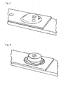
- FIG. 7 shows a by means of the melt pressure during injection molding introduced into a metal bead.
- Fig. 8 shows a schematic perspective view of a introduced by means of the melt pressure during injection molding in a metal bead, in which the injection-molded plastic has passed through a crack in material.
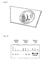
- Fig. 9 illustrates in schematic perspective view an incipient cracking, which was generated by a high melt pressure in injection molding.
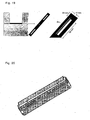
- the Fig. 10 illustrates different variants of slot geometries, which can be introduced for the production of clinch connections in the sheet.
- the length, width and shape of the slots were varied to determine the influence of slot geometry on sheet metal forming and the resulting mechanical strengths of the clinch connection.
- the standard geometry was the vertical slot (perpendicular to the test load) with 10 mm length and 0.5 mm width. The comparison of the strength of these variants is discussed with the results of the mechanical test. While the slot direction has no influence on the forming behavior, it could be improved with the Phillips by 2-3%.
- the variation of the slot length and width gave the following results: With a large slot width, the achievable deformation is reduced, and the clinch connection resembles a riveted joint. The length of the sheet has little influence on the forming.
- the pressure detection in the forming zone of the light metal sheet plays an important role.
- a pressure sensor was placed in each case before and after the forming cavity.
- a temperature sensor was introduced in the tool to measure the sheet temperature during forming.
- the pressure was varied as a reprint by setting the switching point so that no re-forming took place without reprinting.
- the pressure was gradually increased by 50 of the 100 bar until it came to the breaking of the sheet.
- the max. Forming (u) and the forming radius (r) set in relation to each other.
- FIG. 11 illustrates the relationship between maximum deformation u and the forming radius r at a dome-shaped bead (left diagram) or a roof-shaped bead (right diagram).
- the schematic diagram of Fig. 12 illustrates the forming behavior of aluminum and magnesium when introducing beads or when clinching the sheets.
- FIG. 13 The sectional view of the Fig. 13 illustrates a cavity of different diameters (5 mm, 10 mm, 20 mm) and different depths (4 ... 8 mm), which could also have different edge radii (2 ... 6 mm). The results are discussed below.
- Sheet metal characterization has shown that elevated temperature forming could be improved so that a positive contribution to forming can be expected from the melt temperature present in the injection molding process, as shown by the graph of the Fig. 14 is clarified.
- Fig. 15 illustrates this relationship, which shows a more or less strong influence of the selected preheat temperature on the achievable forming ratio (u / r).
- the melt temperature may have an indirect influence on its formability by heating the sheet.
- the diameter of the Umformkavtician is important. Three different 10, 20 and 30 mm forming cavities were used. In the production of beads could be achieved at the same pressure with a larger Umformkavtician a larger deformation. When using a small diameter of Umformkavtician the necessary pressure for a breakage of the sheet could be significantly increased. Since carrying hybrid components usually can have larger forming zones than in the present studies, larger transformations at lower pressures can be achieved. It could be shown that the clinch forming shows only a small dependence on the forming diameter.
- the diagram of Fig. 16 illustrates the relationship between forming diameter (0 ... 30 mm) and the achievable forming ratio (u / r) at various injection pressures (100 bar, 400 bar), in each case for magnesium and aluminum.
- Another parameter is formed by the edge radius of the Umformkavtician. While the standard geometry of the trials was a 20 mm diameter with R2 edge radius, a larger radius of R6 was also used. As a result, the stress in the forming zone can be reduced, whereby a greater pressure can be applied, which leads to a larger deformation. With the edge radius of R6, a significant improvement in the forming could be achieved over the entire pressure range used. In comparison to the radius R2, the maximum deformation (fracture) of aluminum sheet was increased from 48% to 87% and for magnesium sheet from 31% to 77%. Thus, a suitable forming geometry for achieving a desired deformation of the light metal sheet of great importance.
- Fig. 18 illustrates the relationship between injection pressure, forming ratio and edge radius. It can be seen that the achievable forming ratio also increases with a given injection pressure with a larger edge radius.
- the standard sheet thickness was 1.5 mm for magnesium and aluminum, the latter also being used with 1 and 2 mm. All sheet thicknesses could be reshaped well, but the pressure requirement was very different.
- the forming behavior of magnesium and aluminum sheet as well as the bond strength of the clinch joint are measured and compared with the conventional rivet composite.
- the geometry of the clinch slot also influences the strength of the connection with the forming behavior.
- a test plan for the local forming of sheet metal was carried out. Forming behavior, geometry, clinching, load capacity and process control were compared.
- the strength could be increased by increasing the diameter of the forming cavity, although the slot dimensions were 10 x 0.5 mm in all three cases. This is because with increasing the diameter of a larger deformation (similar to a bead) takes place, which can accommodate higher forces in the test direction.
- the area for forming an additional adhesive bond in the forming cavity also increases.
- FIGS. 19 to 22 show, the Fig. 19 in schematic representations of the process of introducing longitudinal beads in a U-shaped support member from which a hybrid component is made.
- longitudinal beads are introduced into the base area in a carrier component by the melt pressure.
- the aim of this change is to improve the resistance of the wearer to bending loads.
- the longitudinal beads may, for example, have a length of about 90 mm, a width of about 10 mm, a depth of up to about 4 mm and an edge radius of about 4 mm.
- FIG. 20 shows the finished shaped support member accordingly Fig. 19 , which is additionally provided with a series of clinch connections.
- the longitudinal beads and the clinch connections in the bottom region of the carrier can be integrated, for example, by simple, replaceable strips in the bottom of a nozzle-side mold insert.
- the strips may preferably be exchangeable from the front.
- the connecting elements for attaching the strips should not be in areas of the laterlyformenden rib structure in order to avoid unwanted deterioration of the component surfaces.
- FIG. 21 show in the process of introducing Clinchtagenen in a U-shaped support member from which a hybrid component according to the invention is made.
- the clinch connections can optionally be aligned with each other or slightly offset from one another.
- the clinch composites can be reminiscent of the execution of conventional rivet joints in order to ensure a comparability of different form-fitting composites.
- the clinch openings may, for example, each have a diameter of about 12 mm, a depth of up to about 4 mm and an edge radius of about 4 mm.
- diagonal beads can furthermore be embossed on the flanks of such a carrier component.
- the perspective part of the Fig. 22 illustrates a diagonal bead, which is in a flank of a U-shaped Carrier component accordingly Fig. 21 is introduced.
- a frame in the new nozzle-side tool insert is provided, which should enable the demoulding of the resulting diagonal beads undercuts in the component.
- hybrid synergies exploit material synergies.
- process-related, material and constructive aspects must be equally considered.
- Good matching allows lightweight structural components with good mechanical properties.
- the design of the positive and / or material-locking connections between the components occupies a central position.
- form-fitting connections are formed.
- the design of plastic ribs should aim at a local and load-dependent reinforcement of the metal insert part, so that e.g. At bending loads buckling of Einlegeteilflanken can be prevented. In the case of a torsional load with diagonal ribs a parallel displacement of Einlegeteilflanken is prevented.
Landscapes
- Engineering & Computer Science (AREA)
- Manufacturing & Machinery (AREA)
- Mechanical Engineering (AREA)
- Injection Moulding Of Plastics Or The Like (AREA)
Description
Die Erfindung betrifft ein umgeformtes flächiges Halbzeug, ein Struktur- bzw. Hybridbauteil und ein Verfahren zur Herstellung eines derartigen Halbzeugs bzw. Bauteils.The invention relates to a shaped flat semifinished product, a structural or hybrid component and a method for producing such a semifinished product or component.
Insbesondere zur Gewichtseinsparung können bei vielen Anwendungsfällen vorhandene Blechstrukturen durch Kunststoffteile ersetzt werden. Oftmals genügen jedoch die dadurch erzielten Bauteileigenschaften nicht den Festigkeits- und/oder Verformungsanforderungen. Zur gezielten Beeinflussung der Eigenschaften von Konstruktionsbauteilen bei möglichst geringem Bauteilgewicht können die Materialien derart kombiniert werden, dass sich die gewünschten Zielkonflikte lösen lassen. So lassen sich dünnwandige Blechstrukturen durch eine geeignete Kombination mit Kunststoffstrukturen leichter als eine vergleichbare Struktur ganz aus Blech und vielfach auch kostengünstiger fertigen. Dennoch weisen diese Bauteile eine ausreichende mechanische Leistungsfähigkeit auf. Der Kunststoff kann dabei einerseits zu einer Stabilisierung des Blechs dienen, was sich in einer erhöhten Knick- bzw. Beulsteifigkeit niederschlagen kann, so dass die mechanischen Eigenschaften des Blechs optimal genutzt werden können. Andererseits ermöglicht der Kunststoff durch seine rationelle Verarbeitbarkeit und die sich ergebenden konstruktiven Freiheiten oftmals große Kostenreduzierungen.In particular, to save weight, existing sheet metal structures can be replaced by plastic parts in many applications. Often, however, the component properties achieved thereby do not meet the strength and / or deformation requirements. The materials can be combined in such a way that the desired target conflicts can be solved in order to influence the properties of construction components with the lowest possible component weight. Thus, thin-walled sheet metal structures can be manufactured more easily from sheet metal and, in many cases, more cost-effectively, by means of a suitable combination with plastic structures than a comparable structure. Nevertheless, these components have sufficient mechanical performance. The plastic can on the one hand serve to stabilize the sheet, which can be reflected in an increased buckling or buckling stiffness, so that the mechanical properties of the sheet can be optimally utilized. On the other hand, the plastic often allows great cost reductions due to its rational processability and the resulting design freedom.
Die meist aus Metall und Kunststoff bestehenden Teile werden üblicherweise als Hybridbauteile bezeichnet und lassen sich aufgrund ihrer vielfältigen konstruktiven Freiheitsgrade für die unterschiedlichsten Zwecke einsetzen, bspw. als Konstruktionselemente im Fahrzeug- oder Flugzeugbau. Die Hybridbauteile weisen den besonderen Vorteil auf, dass gezielt die Vorteile der unterschiedlichen Werkstoffe genutzt und miteinander kombiniert werden können.The mostly made of metal and plastic parts are commonly referred to as hybrid components and can be used for a variety of purposes due to their diverse constructive degrees of freedom, for example. As structural elements in vehicle or aircraft. The hybrid components have the particular advantage that specifically the advantages of different materials can be used and combined with each other.
Bei den bisher bekannten Hybridbauteilen werden vor allem großflächige, vorgeformte metallische Teile bzw. umgeformte Bleche in ein Spritzgießwerkzeug eingelegt und mit zusammenhängenden Kunststoffbereichen umspritzt. Die an dem Metallteil angespritzten Kunststoffstrukturen, die oft mit Verstärkungsrippen versehen sind, erhöhen die Stabilität und die Tragfähigkeit des Metallteils unter verschiedenen auftretenden Beanspruchungen, da auf diese Weise die einwirkenden Kräfte gezielt in das Bauteil eingeleitet und dort verteilt werden können. Dieses Verfahren wird oftmals auch als In-Mould-Assembly (IMA) bezeichnet, da hierbei die Kunststoffstrukturen an die Blechstruktur angespritzt werden. Davon kann das sog. Post-Moulding-Assembly (PMA) unterschieden werden, bei dem beide Komponenten getrennt hergestellt und anschließend miteinander verbunden werden.In the hitherto known hybrid components especially large-scale, preformed metallic parts or formed sheets are placed in an injection mold and encapsulated with coherent plastic areas. The molded plastic structures on the metal part, which are often provided with reinforcing ribs, increase the stability and the load capacity of the metal part under various stresses occurring, since in this way the forces acting can be selectively introduced into the component and distributed there. This method is often referred to as in-mold assembly (IMA), since in this case the plastic structures are molded onto the sheet metal structure. Of these, the so-called. Post-molding assembly (PMA) can be distinguished, in which both components are manufactured separately and then connected together.
Aus der
Die
Die
Ein erstes Ziel der Erfindung besteht darin, ein Hybridbauteil zur Verfügung zu stellen, das bei einfacher Herstellbarkeit verbesserte mechanische Eigenschaften aufweist.A first object of the invention is to provide a hybrid component which has improved mechanical properties with ease of manufacture.
Dieses erste Ziel der Erfindung wird mit dem Gegenstand des unabhängigen Anspruchs 1 erreicht. Merkmale vorteilhafter Weiterbildungen der Erfindung ergeben sich aus den davon abhängigen Ansprüchen.This first object of the invention is achieved with the subject matter of
Ein vorgeformtes bzw. umgeformtes flächiges Halbzeug mit den Merkmalen des Anspruchs 1 umfasst wenigstens eine versteifende Einlage aus Metall oder Kunststoff, die zumindest teilweise formschlüssig in spritzgegossenem Kunststoff eingebettet ist. Die versteifende Einlage weist zumindest einen Bereich auf, der primär vom Schmelzedruck des im Spritzgießverfahren verarbeiteten Kunststoffes dauerhaft verformt ist. Die versteifende Einlage kann insbesondere aus Metallblech bestehen, wobei hier die unterschiedlichsten Materialien und Blechdicken zum Einsatz kommen können, je nach geforderter Bauteilfestigkeit und gewünschtem Anwendungsfall. Als Material für das Metallblech eignet sich insbesondere Leichtmetall wie Aluminium- oder Magnesiumlegierungen. Daneben kann jedoch auch herkömmliches Stahlblech bzw. hochfeste Stahlbleche zum Einsatz kommen. Das Metall- oder Kunststoffblech ist durch den spritzgegossenen Kunststoff derart plastisch verformt, dass eine Sicke, ein Ausbruch oder dergleichen in der versteifenden Einlage gebildet ist, die formschlüssig mit dem gespritzten Kunststoff verbunden ist, so dass ein mechanisch sehr widerstandsfähiges und individuell in seinen Festigkeitseigenschaften einstellbares Hybridbauteil gebildet ist.A preformed or formed flat semi-finished product with the features of
Die versteifende Einlage kann wie erwähnt insbesondere aus Metallblech gebildet sein. Als versteifende Einlage eignet sich jedoch auch Kunststoff, insbesondere Verbundkunststoffe wie GFK, CFK oder dergleichen. Ein wesentlicher Aspekt der Erfindung besteht darin, dass eine direkte plastische Umformung oder eine Bruchstelle der versteifenden Einlage und die Ausbildung einer formschlüssigen Verbindung eines Hybridbauteils durch den Schmelzedruck des spritzgegossenen Kunststoffes erfolgt. Auf diese Weise kann eine Prozessintegration durch die Herstellung von Verbindungen direkt im Werkzeug unter Wegfall der Vorarbeit an der versteifenden Einlage erreicht werden.The stiffening insert may, as mentioned, be formed in particular from sheet metal. As stiffening insert, however, is also plastic, in particular composite plastics such as fiberglass, CFRP or the like. An essential aspect of the invention is that a direct plastic deformation or a breaking point of the stiffening insert and the formation of a positive connection of a hybrid component by the melt pressure of the injection-molded plastic. In this way, a process integration can be achieved by the production of compounds directly in the tool with the elimination of the pre-work on the stiffening insert.
Wenn im vorliegenden Zusammenhang von Einspritzdruck, Schmelzedruck und Nachdruck beim Spritzgießvorgang die Rede ist, so sollen diese Begriffe nachfolgend kurz definiert werden. Der Schmelzedruck wirkt überall dort, wo flüssige Schmelze strömt, was während der Einspritzphase der Fall ist. Der Schmelzedruck kann jedoch auch noch in der sog. Nachdruckphase wirken, wenn die flüssige Schmelze unter einen (quasi-)statischen Druck gesetzt wird. Somit ist sowohl in der Einspritzphase als auch bei der Nachdruckphase eine Umformung möglich, da bei beiden Phasen jeweils ein Schmelzedruck auf das Halbzeug wirkt. Entsprechend dieser Definition wird im vorliegenden Zusammenhang meist der präzisere Begriff "Schmelzedruck" anstelle des Begriffs "Einspritzdruck" verwendet.If in the present context of injection pressure, melt pressure and emphasis during injection molding is mentioned, these terms should be briefly defined below. The melt pressure acts wherever liquid melt flows, which is the case during the injection phase. However, the melt pressure can still act in the so-called. Nachdruckphase when the liquid melt is placed under a (quasi) static pressure. Thus, a deformation is possible both in the injection phase and during the holding pressure phase, since in both phases a respective melt pressure acts on the semifinished product. According to this definition, the more precise term "melt pressure" is used in the present context instead of the term "injection pressure".
Eine bevorzugte Ausgestaltung der Erfindung sieht vor, dass der verformte Bereich der Einlage zumindest abschnittsweise durchbrochen ist. Hierbei bricht oder reißt das Blech bzw. die Kunststoffeinlage durch die Erhöhung des Schmelzedrucks, so dass der eingespritzte Kunststoff anschließend durch die Bruchstelle hindurch in die Umformkavität fließen und den Formschluss herstellen kann. Durch eine geeignete Gestaltung der Umformkavität und der Prozessführung ist es möglich, den Blechbruch bzw. den Bruch der Kunststoffeinlage zu kontrollieren. Mit dem Schmelzedruck kann die Einlage umformt und/oder durchbrochen werden, was die rationelle Herstellung von Sicken und sogenannten Clinchverbindungen ermöglicht. In Versuchen konnte nachgewiesen werden, dass sich sowohl bei Magnesiumblech als auch bei Aluminiumblech Umformgrade erreichen lassen, wie sie ansonsten typischerweise nur mit Umformverfahren erreichbar sind, die einen gesonderten Bearbeitungsschritt erforderlich machen. Zudem sind verschiedene Gestaltungen der Clinchverbindungen denkbar, die zum Teil auch ohne eine vorherige Bearbeitung des Blechs auskommen.A preferred embodiment of the invention provides that the deformed region of the insert is at least partially broken. This breaks or tears the sheet or the plastic insert by increasing the melt pressure, so that the injected plastic then flow through the fracture point into the Umformkavität and can make the positive connection. By a suitable design of the Umformkavität and the process control, it is possible to control the sheet metal breakage or breakage of the plastic insert. With the melt pressure, the insert can be transformed and / or broken, which allows the efficient production of beads and so-called clinch connections. Experiments have shown that both magnesium sheet and aluminum sheet can achieve degrees of deformation which can otherwise typically only be achieved with forming processes which require a separate processing step. In addition, various designs of the clinch connections are conceivable, which partly make do without a previous processing of the sheet.
Die Einlage kann im verformten Bereich wenigstens eine vorgeformte Sicke bzw. einen vorgeformten Durchbruch, insbesondere einen Schlitz oder mehrere Schlitze aufweisen. In dem vom Schmelzedruck des spritzgegossenen Kunststoffes verformten Bereich ist wenigstens ein Durchbruch bzw. Schlitz aufgeweitet und/oder in zumindest einem Randbereich erweitert. Vorzugsweise ist der vom Schmelzedruck des spritzgegossenen Kunststoffes verformte Bereich der Einlage weitgehend vollständig vom spritzgegossenen Kunststoff umgeben bzw. in diesem eingebettet.The insert may have in the deformed region at least one preformed bead or preformed opening, in particular one slot or a plurality of slots. In the area deformed by the melt pressure of the injection-molded plastic, at least one opening or slot is widened and / or widened in at least one edge area. Preferably, the area of the insert which is deformed by the melt pressure of the injection-molded plastic is largely completely surrounded by the injection-molded plastic or embedded therein.
Eine ebenfalls sehr vorteilhafte Variante der Erfindung kann vorsehen, dass Sicken oder Einprägungen nahezu beliebiger Form während des Spritzgießvorganges in das Material der Einlage eingebracht werden können, insbesondere in Metalleinlagen aus Stahl- oder Leichtmetallblech. So können bspw. in Trägerbauteile geeignete Längssicken eingeprägt werden, die zur Materialversteifung beitragen, ohne dass das Material hierbei überdehnt oder durchbrochen werden muss. Alternativ oder zusätzlich können die erwähnten Clinchverbindungen hergestellt werden. Darüber hinaus kann es sinnvoll sein, an geeigneten Stellen Diagonalsicken o. dgl. einzubringen, was die Torsionssteifigkeit derartiger Trägerbauteile erhöhen kann.A likewise very advantageous variant of the invention can provide that beads or indentations of virtually any shape can be introduced into the material of the insert during the injection molding process, in particular in metal inserts made of steel or light metal sheet. Thus, for example, suitable longitudinal beads can be embossed in carrier components, which contribute to material stiffening, without the material having to be overstretched or broken. Alternatively or additionally, the mentioned clinch connections can be produced. In addition, it may be useful at appropriate locations Diagonalsicken o. The like. To bring what can increase the torsional stiffness of such support components.
Das erfindungsgemäße vorgeformte flächige Halbzeug eignet sich insbesondere zur Herstellung einer Verbundstruktur bzw. eines Hybridbauteils gemäß Anspruch 10. Derartige Strukturen bzw. Bauteile können als vormontierbare Konstruktionselemente für vielfältige Zwecke eingesetzt werden, bspw. im Fahrzeugbau, im Schienenfahrzeug- oder im Flugzeugbau.The preformed flat semifinished product according to the invention is particularly suitable for producing a composite structure or a hybrid component according to
Ein weiteres Ziel der Erfindung besteht darin, ein rationelles Verfahren zur Herstellung eines vorgeformten flächigen Halbzeuges zur Verfügung zu stellen, das zur Ausbildung von leichten und stabilen Hybridbauteilen geeignet ist.Another object of the invention is to provide a rational method for producing a preformed sheet semi-finished product which is suitable for forming lightweight and stable hybrid components.
Dieses weitere Ziel der Erfindung wird mit einem Verfahren gemäß unabhängigem Anspruch 12 erreicht. Merkmale vorteilhafter Weiterbildungen ergeben sich aus den davon abhängigen Ansprüchen.This further object of the invention is achieved by a method according to
Ein erfindungsgemäßes Verfahren zur Herstellung eines flächigen Halbzeugs bzw. einer Verbundstruktur, das/die wenigstens eine versteifende Einlage aus Metall oder Kunststoff aufweist, die im Spritzgießverfahren zumindest teilweise formschlüssig mit Kunststoff umspritzt wird, sieht vor, dass die versteifende Einlage zumindest in einem Bereich mittels des Schmelzedrucks des im Spritzgießverfahren verarbeiteten Kunststoffes dauerhaft verformt wird. Das erfindungsgemäße Verfahren ermöglicht die Herstellung von Hybridbauteilen bzw. -halbzeugen, die aus mindestens zwei unterschiedlichen Materialien bestehen, typischerweise aus Leichtmetallblech und dieses umschließenden Kunststoff. Mittels des Verfahrens können in einfacher und sehr effizienter Weise mittels eines einzigen Verarbeitungsschrittes die gewünschten Hybridstrukturen hergestellt werden, die bei sehr geringem Gewicht eine hohe Strukturfestigkeit bieten können. Die Formgebung ermöglicht es, dem Bauteil ein gewünschtes Festigkeits- und Verformungsverhalten zu geben, was mit herkömmlichen Bauteilen nur mit deutlich höherem Fertigungsaufwand und meist mit höheren Bauteilgewichten realisierbar ist.An inventive method for producing a flat semi-finished product or a composite structure, which / has at least one stiffening insert made of metal or plastic, which is encapsulated in the injection molding at least partially positive fit with plastic, provides that the stiffening insert at least in one area by means of Melt pressure of the processed by injection molding plastic is permanently deformed. The inventive method allows the production of hybrid components or semifinished products, which consist of at least two different materials, typically made of light metal sheet and this enclosing plastic. By means of the method, the desired hybrid structures can be produced in a simple and very efficient manner by means of a single processing step, which can offer a high structural strength at very low weight. The shaping makes it possible to give the component a desired To give strength and deformation behavior, which is feasible with conventional components only with significantly higher manufacturing costs and usually with higher component weights.
Eine bevorzugte Variante des erfindungsgemäßen Verfahrens sieht vor, dass der vom Schmelzedruck des spritzgegossenen Kunststoffes verformte Bereich der Einlage plastisch verformt wird. Eine alternative oder damit kombinierbare Ausführungsvariante dieses Verfahrens sieht vor, dass der verformte Bereich der Einlage vom Schmelzedruck des Kunststoffes zumindest abschnittsweise durchbrochen wird. Insbesondere kann im verformten Bereich der Einlage während des Spritzgießverfahrens zumindest ein Versagensbruch oder -riss erzeugt werden. Ggf. können auch mehrere Risse auftreten. Der typische Schmelzedruck beim Spritzgießverfahren von mehr als 200 bar kann nach Füllen der Form gezielt erhöht werden, um die gewünschten Materialbrüche bzw. -risse zu erzeugen, die zum gewünschten verbesserten Formschluss zwischen der versteifenden Metall- bzw. Kunststoffeinlage und dem spritzgegossenem Kunststoff führen.A preferred variant of the method according to the invention provides that the area of the insert deformed by the melt pressure of the injection-molded plastic is plastically deformed. An alternative or combinable variant of this method provides that the deformed region of the insert is at least partially broken by the melt pressure of the plastic. In particular, at least one failure break or tear may be generated in the deformed region of the insert during the injection molding process. Possibly. can also occur several cracks. The typical melt pressure in the injection molding process of more than 200 bar can be selectively increased after filling the mold to produce the desired material fractures or cracks, which lead to the desired improved positive connection between the stiffening metal or plastic insert and the injection-molded plastic.
Bei einer weiteren bevorzugten Variante des erfindungsgemäßen Verfahrens wird die Einlage im zu verformenden Bereich vor dem Spritzgießen mit wenigstens einer vorgeformte Sicke bzw. einem vorgeformten Durchbruch, insbesondere mit einem Schlitz oder mehreren Schlitzen, versehen. Hierdurch kann beim Füllen der Form erreicht werden, dass in dem vom Schmelzedruck des spritzgegossenen Kunststoffes verformten Bereich der wenigstens eine Durchbruch bzw. Schlitz aufgeweitet und/oder in zumindest einem Randbereich erweitert wird. Weiterhin kann vorgesehen sein, dass der vom Schmelzedruck des spritzgegossenen Kunststoffes verformte Bereich der Einlage weitgehend vollständig vom spritzgegossenem Kunststoff umgeben bzw. in diesem eingebettet wird, wodurch das gewünschte Hybridbauteil gebildet wird, das bei reduziertem Gewicht eine höhere Festigkeit aufweisen kann als ein vergleichbares Stahlblechbauteil oder eines aus spritzgegossenem Kunststoff.In a further preferred variant of the method according to the invention, the insert is provided in the area to be deformed with at least one pre-formed bead or preformed opening, in particular one or more slots, prior to injection molding. In this way, it can be achieved during filling of the mold that, in the region deformed by the melt pressure of the injection-molded plastic, the at least one breakthrough or slot is widened and / or widened in at least one edge region. Furthermore, it can be provided that the area of the insert deformed by the melt pressure of the injection-molded plastic is substantially completely surrounded or embedded in the injection-molded plastic, whereby the desired hybrid component is formed, which with reduced weight can have a higher strength than a comparable sheet steel component or one of injection-molded plastic.
Eine weitere vorteilhafte Variante des erfindungsgemäßen Verfahrens kann vorsehen, dass ein als Einlage verwendetes Metallblech vor oder während des Spritzgießens zusätzlich erwärmt wird. Ggf. kann das Metallblech mittels einer Temperierung des Werkzeugs erwärmt werden.A further advantageous variant of the method according to the invention can provide that a metal sheet used as insert is additionally heated before or during injection molding. Possibly. the metal sheet can be heated by means of a temperature control of the tool.
Zusammenfassend ergeben sich die folgenden Aspekte der Erfindung:In summary, the following aspects of the invention result:
Spritzgegossene Kunststoff/Metall-Hybridstrukturen kombinieren die strukturellen Vorteile beider Werkstoffe, wodurch sich ihr Leistungsvermögen deutlich erhöht. Einfach umgeformte Bleche werden durch eine Kunststoffverrippung versteift und geometrisch stabilisiert, im Arbeitsaufnahmevermögen verbessert sowie gleichzeitig um Funktionselemente erweitert. Die Nutzung werkstofflicher, konstruktiver und fertigungstechnischer Synergien ermöglicht eine integrierte, kostengünstige Fertigung tragender Leichtbauteile. Die resultierenden Bauteileigenschaften werden durch Werkstoffauswahl, Konstruktion und Prozessführung bestimmt.Injection molded plastic / metal hybrid structures combine the structural advantages of both materials, significantly increasing their performance. Simply formed sheets are stiffened by a plastic ribbing and geometrically stabilized, improved in work capacity and at the same time extended to functional elements. The use of material, constructive and manufacturing synergies enables an integrated, cost-effective production of load-bearing lightweight components. The resulting component properties are determined by material selection, design and process control.
Während Stahleinlegeteile in der Hybridbauweise etabliert sind, wird auch der Einsatz von Leichtmetallen in Erwägung gezogen. Das ökonomische und ökologische Interesse gilt der Einsparung von Gewicht, Energie und Kosten durch eine Leichtbauweise. Neben Aluminium ist Magnesiumblech aufgrund seiner niedrigen Dichte von besonderem Interesse, zumal für die nächsten Jahre deutliche Preissenkungen prognostiziert werden und die Rezyklierbarkeit im Vergleich zu Stahl verbessert ist. Zudem besitzen beide Leichtmetalle eine den in der Hybridtechnik verwendeten Standardthermoplasten ähnliche Wärmeausdehnung, was zu verringerten thermische Bauteilbelastungen führt.While steel inserts are established in hybrid construction, the use of light metals is also considered. The economic and ecological interest is the saving of weight, energy and costs through a lightweight construction. In addition to aluminum, magnesium sheet is of particular interest due to its low density, especially since significant price reductions are forecast for the next few years and the recyclability is improved compared to steel. In addition, both light metals have a thermal expansion similar to the standard thermoplastics used in hybrid technology, resulting in reduced thermal component loads.
Eine große Herausforderung besteht in der Einleitung und Verteilung der äußeren mechanischen Beanspruchung im Hybridbauteil. Hierfür ist eine angepasste Verbindungstechnik von großer Bedeutung, welche im Anschluss zur Einzelfertigung der Komponenten (Post-Moulding-Assembly, PMA) oder auch integriert im Spritzgießprozess (In-Mould-Assembly, IMA) erfolgen kann. Die PMA-Technik wird durch Kleben oder Kragenfügen realisiert. Beim IMA basieren die Verbindungselemente in der Regel auf Formschluss z.B. durch Hinterschneidungen oder Bohrungen im Blech, und die Herstellung der Hybridstrukturen ist gleichzeitig sowohl Urform- als auch Montageprozess. Die Notwendigkeit mechanisch fester und belastungsgerecht platzierter Verbindungselemente steigt mit der Bauteilkomplexität und der Anzahl der Einlegeteile. Wichtiges Ziel für eine rationelle Fertigung ist die Prozesskettenverkürzung, welche beim IMA durch Zusammenführung einzelner Prozessschritte im Spritzgießwerkzeug erreicht werden kann.A major challenge is the initiation and distribution of the external mechanical stress in the hybrid component. For this purpose, an adapted connection technology is of great importance, which can then take place for the individual production of the components (post-molding assembly, PMA) or integrated in the injection molding process (in-mold assembly, IMA). The PMA technique is realized by gluing or collar joining. In the case of the IMA, the connecting elements are usually based on positive locking, e.g. By undercuts or holes in the sheet metal, and the production of hybrid structures is both original and assembly process. The need for mechanically strong and load-bearing placed fasteners increases with component complexity and the number of inserts. An important goal for efficient production is the shortening of the process chain, which can be achieved at the IMA by merging individual process steps in the injection molding tool.
Die direkte Umformung von Leichtmetallblechen durch den Schmelzedruck zur Herstellung formschlüssiger Verbindungen eröffnet eine neue Möglichkeit der Prozessintegration. Hinzu kommt, dass die Umformbarkeit der Leichtmetallbleche bei hohen Temperaturen, wie sie im Spritzgießprozess vorliegen, deutlich zunimmt. Die Umformbarkeit von Leichtmetallblechen wurde in einem Modell-Werkzeug mit Umformkavität überprüft. Es wurden Aluminium- und Magnesiumbleche eingesetzt und mit dem in der Hybridtechnik verwendeten Standardthermoplasten PA6-GF30 angespritzt. Das Blech wurde eingelegt und durch den Kunststoff-Schmelzedruck in die Umformkavität hineindrückt. Es können zwei Varianten unterschieden werden: Die Einbringung von Sicken sowie die Herstellung einer formschlüssigen Clinchverbindung. Beim Clinchen wurden als Vorbearbeitung im Blech Schlitze verschiedener Geometrien eingebracht.The direct forming of light metal sheets by the melt pressure for the production of positive connections opens up a new possibility of process integration. In addition, the formability of the light metal sheets at high temperatures, as present in the injection molding process, increases significantly. The formability of light metal sheets was tested in a model tool with Umformkavität. Aluminum and magnesium sheets were used and injection-molded with the standard thermoplastic PA6-GF30 used in hybrid technology. The sheet was inserted and pressed into the Umformkavität by the plastic melt pressure. Two variants can be distinguished: the introduction of beads and the production of a positive clinch connection. During clinching, slits of various geometries were introduced as preprocessing in the sheet metal.
Das Umformverhalten von Magnesium- und Aluminiumblech sowie die Verbundfestigkeit der Clinchverbindung wurden charakterisiert und mit dem konventionellen Nietverbund verglichen. Die Geometrie des im Blech eingebrachten Clinch-Schlitzes beeinflusst mit dem Umformverhalten die Festigkeit der Verbindung. Die Verbundfestigkeiten der Verbindungen wurden mechanisch auf Zugscherung geprüft.The forming behavior of magnesium and aluminum sheet as well as the bond strength of the clinch joint were characterized and compared with the conventional rivet composite. The geometry of the clinch slot introduced in the sheet metal influences the strength of the connection with the forming behavior. The bond strengths of the joints were mechanically tested for tensile shear.
Es wurden unter anderem Probekörper mit unterschiedlichen Clinchverbunden (Querschnittsfläche 5...10 mm2) hergestellt, mechanisch geprüft und die Festigkeit mit Nietverbunden (Durchmesser 3 mm, Querschnittsfläche 7 mm2) verglichen. Bei diesen Versuchen hat sich gezeigt, dass alle hergestellten Clinchverbunde mechanisch höher belastbar sind als der Nietverbund. Dies kann mit einer Vergrößerung von Verbundquerschnitt und -höhe infolge der Blechumformung und der damit verbundenen vergrößerten Aufnahmefläche der mechanischen Spannungen begründet werden.Among other things, specimens with different clinch connections (
Eine weitere Prozessintegration konnte durch die Herstellung von Verbindungen direkt im Werkzeug unter Wegfall der Vorarbeit des Blechs erreicht werden. Die Machbarkeit wurde aufgezeigt, indem das Blech durch Erhöhung des Schmelzedrucks bricht und der Kunststoff anschließend durch die Bruchstelle hindurch in die Umformkavität fließt und den Formschluss herstellt. Es konnte gezeigt werden, dass die Verbundfestigkeit solcher ohne Blechvorarbeit hergestellter Verbundteile die der Clinch- und Nietverbunde übertrifft. Für eine optimierte Herstellung solcher Verbindungen ist das Versagen des Leichtmetallblechs zu untersuchen. Die Geometrie der Bruchzone bestimmt schließlich die mechanische Belastbarkeit der Verbindung. Durch eine geeignete Gestaltung von Umformkavität und Prozessführung erscheint es möglich, den Blechbruch zu kontrollieren.Further process integration could be achieved through the production of connections directly in the tool, eliminating the preliminary work of the sheet. The feasibility has been demonstrated by breaking the sheet by increasing the melt pressure and then flowing the plastic through the fracture point into the forming cavity to form fit. It could be shown that the bond strength of such composite parts produced without sheet metal pre-work exceeds that of the clinch and rivet joints. For an optimized production of such compounds, the failure of the light metal sheet is to be investigated. Finally, the geometry of the fracture zone determines the mechanical strength of the joint. By a suitable design of Umformkavität and process management, it seems possible to control the sheet metal breakage.
Somit konnte nachgewiesen werden, dass das lokale Umformen von Metallblechen direkt im Spritzgießwerkzeug eine vielversprechende Möglichkeit der formschlüssigen Verbindungstechnik spritzgegossener Kunststoff/Metall-Hybridstrukturen darstellt. Mit dem Spritzdruck kann das Blech umgeformt oder durchbrochen werden, was die rationelle Herstellung von Sicken und Clinchverbindungen ermöglicht. Es sind verschiedene Gestaltungen der Clinchverbindungen denkbar, die z.T. auch ohne eine Vorbearbeitung des Blechs auskommen.Thus, it could be demonstrated that the local forming of metal sheets directly in the injection mold represents a promising possibility of the positive connection technique of injection molded plastic / metal hybrid structures. With the injection pressure, the sheet can be reshaped or broken, which allows the efficient production of beads and clinch connections. There are various designs of Clinchverbindungen conceivable that z.T. even without a pre-processing of the sheet get along.
Bei der Einbringung von Sicken ist durch die Gestaltung von Prozessführung und Geometrie eine Optimierung des Umformverhaltens möglich. Es konnten sowohl bei Magnesium als auch bei Aluminium Umformgrade wie beim Hydroformen erreicht werden. Bei Clinchverbindungen ist die Geometrie der im Blech eingearbeiteten Schlitzung von zentraler Bedeutung. Die Machbarkeit von Clinchverbunden ohne Blechvorbearbeitung wurde erfolgreich durchgeführt.When embedding beads, it is possible to optimize the forming behavior by designing process control and geometry. It was possible to achieve degrees of deformation both in magnesium and in aluminum as in hydroforming. For clinch joints, the geometry of the slit machined in the sheet is of central importance. The feasibility of Clinchverbunden without sheet metal preparation has been successfully performed.
Die Erfindung wird nachfolgend anhand bevorzugter Ausführungsbeispiele unter Bezugnahme auf die beiliegenden Zeichnungen näher erläutert. Die Ausführungsbeispiele dienen zum besseren Verständnis der wesentlichen Aspekte der Erfindung. Sie beschränken die erfinderische Lehre jedoch in keiner Weise.
-
Fig. 1 zeigt in einem schematischen Schaubild verschiedene Möglichkeiten der Prozessintegration beim Umformen von Leichtmetall im Spritzgießwerkzeug. -
Fig. 2 zeigt in einem schematischen Schaubild die Prozessintegration bei der Herstellung von Hybridbauteilen. -
Fig. 3a zeigt in schematischer Darstellung die Herstellung von Sicken durch den Schmelzedruck. -
Fig. 3b zeigt in schematischer Darstellung die Herstellung einer Clinchverbindung durch den Schmelzedruck. -
Fig. 4 stellt verschiedene Clinchverbindungen einer Nietverbindung gegenüber. -
Fig. 5 verdeutlicht in einem Diagramm die mechanische Festigkeit von Clinchverbindungen gegenüber Nietverbindungen. -
Fig. 6 verdeutlicht die aufeinander folgenden Verfahrensschritte bei der Erzeugung von Verbindungen im Werkzeug ohne Vorarbeiten im Blech. -
Fig. 7 zeigt eine schematische Perspektivdarstellung einer mittels des Schmelzedrucks beim Spritzgießen in ein Blech eingebrachten Sicke. -
Fig. 8 zeigt eine schematische Perspektivdarstellung einer mittels des Schmelzedrucks beim Spritzgießen in ein Blech eingebrachten Sicke, bei welcher der spritzgegossene Kunststoff durch einen Materialriss hindurch getreten ist. -
Fig. 9 verdeutlicht in schematischer Perspektivdarstellung eine beginnende Rissbildung, die durch einen hohen Einspritzdruck bzw. Schmelzedruck beim Spritzgießen erzeugt wurde. -
Fig. 10 verdeutlicht verschiedene Varianten von Schlitzgeometrien, die zur Herstellung von Clinchverbindungen in das Blech eingebracht werden können. -
Fig. 11 verdeutlicht in schematischen Darstellungen anhand möglicher Konturen von Sicken den Zusammenhang zwischen dem Umformgrad und dem Umformradius. -
Fig. 12 zeigt anhand eines Diagramms einen Zusammenhang zwischen Einspritzdruck und Umformverhältnis bei verschiedenen Umformgeometrien. -
Fig. 13 zeigt anhand einer schematischen Schnittdarstellung verschiedene Umformgeometrien, -radien und -tiefen sowie verschiedene Kantenradien von eingebrachten Sicken. -
Fig. 14 zeigt anhand eines Diagramms einen Erwärmungsverlauf während des Umformprozesses. -
Fig. 15 zeigt anhand eines Diagramms den Zusammenhang zwischen der Vorwärmtemperatur des Werkzeugs und dem Umformverhältnis für verschiedene Werkstoffe bzw. Umformgeometrien. -
Fig. 16 zeigt anhand eines Diagramms den Zusammenhang zwischen Umformdurchmesser und Umformverhältnis bei verschiedenen Einspritzdrücken sowie verschiedenen Blechmaterialien. -
Fig. 17 zeigt anhand eines Diagramms den Zusammenhang zwischen Einspritzdruck und Umformverhältnis bei verschiedenen Umformdurchmessern sowie verschiedenen Blechmaterialien. -
Fig. 18 zeigt anhand eines Diagramms den Zusammenhang zwischen Einspritzdruck und Umformverhältnis bei verschieden gewählten Kantenradien sowie verschiedenen Blechmaterialien. -
Fig. 19 zeigt in schematischen Darstellungen den Prozess des Einbringens von Längssicken in ein U-förmiges Trägerbauteil, aus dem ein Hybridbauteil hergestellt wird. -
Fig. 20 zeigt das fertig geformte Trägerbauteil entsprechendFig. 19 in schematischer Perspektivdarstellung. -
Fig. 21 zeigt in schematischen Darstellungen den Prozess des Einbringens von Clinchverbindungen in ein U-förmiges Trägerbauteil, aus dem ein Hybridbauteil hergestellt wird. -
Fig. 22 zeigt in einem perspektivischen Teilausschnitt eine Diagonalsicke, die in eine Flanke eines U-förmigen Trägerbauteils entsprechendFig. 21 eingebracht ist.
-
Fig. 1 shows in a schematic diagram various possibilities of process integration during forming of light metal in the injection mold. -
Fig. 2 shows a schematic diagram of the process integration in the production of hybrid components. -
Fig. 3a shows a schematic representation of the production of beads by the melt pressure. -
Fig. 3b shows a schematic representation of the production of a clinch connection by the melt pressure. -
Fig. 4 contrasts different clinch connections of a riveted joint. -
Fig. 5 illustrates in a diagram the mechanical strength of clinch connections against riveted joints. -
Fig. 6 illustrates the successive steps in the production of connections in the tool without preliminary work in the sheet metal. -
Fig. 7 shows a schematic perspective view of an introduced by means of the melt pressure during injection molding in a metal bead. -
Fig. 8 shows a schematic perspective view of a introduced by means of the melt pressure during injection molding in a metal bead, in which the injection-molded plastic has passed through a crack in material. -
Fig. 9 illustrates in a schematic perspective view of an incipient cracking, which was generated by a high injection pressure or melt pressure during injection molding. -
Fig. 10 illustrates different variants of slot geometries, which can be introduced for the production of clinch connections in the sheet. -
Fig. 11 illustrates in schematic representations on the basis of possible contours of beads the relationship between the degree of deformation and the Umformradius. -
Fig. 12 shows a diagram of a relationship between injection pressure and forming ratio at different Umformgeometrien. -
Fig. 13 shows a schematic sectional view of different Umformgeometrien, radii and depths and different edge radii of introduced beads. -
Fig. 14 shows on the basis of a diagram a heating course during the forming process. -
Fig. 15 shows a diagram of the relationship between the preheating temperature of the tool and the forming ratio for different materials or Umformgeometrien. -
Fig. 16 shows a diagram of the relationship between forming diameter and forming ratio at different injection pressures and different sheet materials. -
Fig. 17 shows the relationship between injection pressure and forming ratio for different forming diameters and different sheet materials on the basis of a diagram. -
Fig. 18 shows a diagram of the relationship between injection pressure and forming ratio at different selected edge radii and various sheet materials. -
Fig. 19 shows in schematic representations the process of introducing longitudinal beads in a U-shaped support member from which a hybrid component is made. -
Fig. 20 shows the finished shaped support member accordinglyFig. 19 in a schematic perspective view. -
Fig. 21 shows in schematic representations the process of introducing clinch joints in a U-shaped support member from which a hybrid component is made. -
Fig. 22 shows in a perspective partial section a diagonal bead, which corresponds to an edge of a U-shaped support memberFig. 21 is introduced.
Das schematische Schaubild der
Ein wichtiger Parameter ist die Einleitung und Verteilung der äußeren mechanischen Beanspruchung in das Hybridbauteil. Hierfür ist eine angepasste Verbindungstechnik von großer Bedeutung, welche im Anschluss zu Einzelteilfertigung der Komponenten (Post-Moulding-Assembly, PMA) oder auch integriert im Spritzgießprozess (In-Moulding-Assembly, IMA) erfolgen kann. Die PMA-Technik wird durch Kleben oder Kragenfügen realisiert. Bei der IMA-Technik basieren die Verbindungselemente i.d.R. auf Formschluss, z.B. durch Hinterschneidungen oder Bohrungen im Blech, so dass die Herstellung der Hybridstrukturen gleichzeitig sowohl ein Urform- als auch ein Montageprozess ist.An important parameter is the initiation and distribution of the external mechanical stress in the hybrid component. This is an adapted connection technology Of great importance, which can be followed by component production of components (post-molding assembly, PMA) or integrated in the injection molding process (in-molding assembly, IMA). The PMA technique is realized by gluing or collar joining. In the case of IMA technology, the connecting elements are usually based on positive locking, for example by undercuts or bores in the metal sheet, so that the production of the hybrid structures is both a primary molding and an assembly process at the same time.
Die Notwendigkeit mechanisch fester und belastungsgerecht platzierter Verbindungselemente steigt mit der Bauteilkomplexität und der Anzahl der Einlegeteile. Wichtiges Ziel für eine rationelle Fertigung ist die Prozesskettenverkürzung, welche beim IMA durch Zusammenführung einzelner Prozessschritte im Spritzgießwerkzeug erreicht werden kann, was anhand der
Die besonderen Verfahrensvorteile werden bei Betrachtung der
Das schematische Schaubild der
Die schematischen Darstellungen der
Die schematische Darstellung der
Eine Prozessintegration konnte durch die Herstellung von Verbindungen direkt im Werkzeug unter Wegfall der Vorarbeit des Blechs erreicht werden.
Die schematischen Darstellungen der
Die
Weitere Versuchsergebnisse bei der Herstellung erfindungsgemäßer Hybridbauteile werden nachfolgend ergänzend diskutiert.Further experimental results in the production of hybrid components according to the invention are discussed in the following.
Da der Druck für die Umformung der bedeutendste Parameter ist, kommt der Druckerfassung in der Umformzone des Leichtmetallblechs eine wichtige Rolle zu. Aus Sicht der Kunststoff-Fließfront wurde jeweils ein Druckaufnehmer vor und nach der Umformkavität platziert. Ebenso wurde im Werkzeug ein Temperaturaufnehmer eingebracht, um die Blechtemperatur beim Umformen zu messen. Der Druck wurde als Nachdruck variiert, indem der Umschaltpunkt so gesetzt wurde, dass ohne Nachdruck keine Umformung stattfand. Der Druck wurde schrittweise um 50 der 100 bar gesteigert bis es zum Bruch des Blechs kam. Bei der Ermittlung der Umformgeometrie im Leichtmetallblech wurden die max. Umformung (u) und der Umformradius (r) zueinander in Verhältnis gesetzt.Since the pressure for forming is the most important parameter, the pressure detection in the forming zone of the light metal sheet plays an important role. Out From the perspective of the plastic flow front, a pressure sensor was placed in each case before and after the forming cavity. Similarly, a temperature sensor was introduced in the tool to measure the sheet temperature during forming. The pressure was varied as a reprint by setting the switching point so that no re-forming took place without reprinting. The pressure was gradually increased by 50 of the 100 bar until it came to the breaking of the sheet. When determining the forming geometry in the light metal sheet, the max. Forming (u) and the forming radius (r) set in relation to each other.
Die schematischen Diagramme der
Das schematische Diagramm der
Bei der Herstellung von Sicken besitzen Aluminium und Magnesium ein ähnliches Umformverhalten. Aufgrund der höheren Bruchspannung von Aluminium erfolgte der Bruch bei 550 bar, während das Magnesiumblech schon bei 450 bar versagte. Es wurde hierbei ein Blech mit einer Stärke von 1,5 mm verwendet, in das eine Sicke von 20 mm Durchmesser und einem Kantenradius von 2 mm (gekennzeichnet durch die Bemaßung 20 mm R2 Umformkavität, 1,5 mm Blechdicke) verwendet. Ein höherer Umformgrad konnte beim Aluminiumblech erreicht werden.In the production of beads aluminum and magnesium have a similar forming behavior. Due to the higher fracture stress of aluminum, the fracture was at 550 bar, while the magnesium sheet failed at 450 bar. A sheet of 1.5 mm thickness was used, into which a bead of 20 mm diameter and an edge radius of 2 mm (characterized by the
Beim Clinchen ist die Umformbarkeit von Aluminium etwas besser als von Magnesium. Es genügt schon ein geringer Druck von 100 bar für eine Umformung von ca. 30%. Ein höherer Druck bewirkt nahezu keine Erhöhung der max. Umformung, da das Blech lediglich bis zu einer bestimmten Schlitzgröße umgeformt wird, wonach der Kunststoff in die Umformkavität fließt und einen Gegendruck bildet.When it comes to clinching, the malleability of aluminum is slightly better than that of magnesium. It is sufficient even a low pressure of 100 bar for a deformation of about 30%. A higher pressure causes almost no increase in the max. Forming, since the sheet is formed only up to a certain slot size, after which the plastic flows into the Umformkavität and forms a counter-pressure.
Weitere Einflüsse des Drucks wurden mit anderen Geometrieparametem verbunden, was anhand der Darstellung der
Die Blechcharakterisierung hat gezeigt, dass die Umformung unter erhöhter Temperatur verbessert werden konnte, so dass von der im Spritgießprozess vorhandenen Schmelzetemperatur ein positiver Beitrag für die Umformung erwartet werden kann, was anhand des Diagramms der
Hierfür wurden mit einem ähnlichen Werkzeugaufbau Temperaturmessungen an der schmelzeseitigen Magnesiumblechoberfläche durchgeführt. Eine Blechvorwärmung durch Konvektionsflamme wurde versucht. Es zeigte sich jedoch, dass die Wärme des Leichtmetallblechs nach dem Schließen des Werkzeugs schnell abgeführt wird, so dass eine Temperatur von 200 °C nicht erreicht werden konnte. Daher wurde die Blechvorwärmung durch unterschiedlich hohe Werkzeugtemperaturen (40 - 100 °C) realisiert. In diesem Temperaturbereich steigt die absolute Umformung der Sicken sowohl bei Aluminium als auch bei Magnesium um ca. 5%. Die Umformung beim Clinchen von Magnesium steigt nur geringfügig an.For this purpose, temperature measurements were carried out on the melt-side magnesium sheet surface using a similar tool design. A plate preheating by Konvektionsflamme was tried. However, it was found that the heat of the light metal sheet is quickly dissipated after closing the tool, so that a temperature of 200 ° C could not be achieved. Therefore, the sheet metal preheating was realized by different high tool temperatures (40 - 100 ° C). In this temperature range, the absolute deformation of the beads in both aluminum and magnesium increases by about 5%. The deformation during clinching of magnesium increases only slightly.
Das schematische Diagramm der
Die Schmelzetemperatur kann durch eine Aufwärmung des Blechs einen indirekten Einfluss auf dessen Umformbarkeit haben.The melt temperature may have an indirect influence on its formability by heating the sheet.
Der Einfluss der Umformgeometrie soll im Folgenden diskutiert werden. Wichtig ist zunächst der Durchmesser der Umformkavität. Drei verschiedene Umformkavitäten mit 10, 20 und 30 mm wurden verwendet. Bei der Herstellung von Sicken konnte bei gleichem Druck mit einer größeren Umformkavität eine größere Umformung erreicht werden. Bei Verwendung eines kleinen Durchmessers der Umformkavität konnte der für einen Bruch des Blechs notwendige Druck deutlich erhöht werden. Da tragende Hybridbauteile in der Regel größere Umformzonen als bei den vorliegenden Untersuchungen aufweisen können, sind auch größere Umformungen bei geringeren Drücken erzielbar. Es konnte gezeigt werden, dass die Clinchumformung eine nur geringe Abhängigkeit vom Umformdurchmesser zeigt.The influence of the forming geometry will be discussed below. First, the diameter of the Umformkavität is important. Three different 10, 20 and 30 mm forming cavities were used. In the production of beads could be achieved at the same pressure with a larger Umformkavität a larger deformation. When using a small diameter of Umformkavität the necessary pressure for a breakage of the sheet could be significantly increased. Since carrying hybrid components usually can have larger forming zones than in the present studies, larger transformations at lower pressures can be achieved. It could be shown that the clinch forming shows only a small dependence on the forming diameter.
Das Diagramm der
Das Diagramm der
Ein weiterer Parameter wird durch den Kantenradius der Umformkavität gebildet. Während die Standardgeometrie der Versuche ein 20 mm Durchmesser mit R2 Kantenradius war, wurde auch ein größerer Radius von R6 eingesetzt. Hierdurch kann die Spannung in der Umformzone reduziert werden, wodurch ein größerer Druck aufgebracht werden kann, der zu einer größeren Umformung führt. Mit dem Kantenradius von R6 konnte über den gesamten verwendeten Druckbereich eine deutliche Verbesserung der Umformung erzielt werden. Im Vergleich zum Radius R2 wurde beim Aluminiumblech die maximale Umformung (Bruch) von 48% auf 87% und beim Magnesiumblech von 31% auf 77% erhöht. Somit ist eine geeignete Umformgeometrie für die Erzielung einer gewünschten Umformung des Leichtmetallblechs von großer Bedeutung.Another parameter is formed by the edge radius of the Umformkavität. While the standard geometry of the trials was a 20 mm diameter with R2 edge radius, a larger radius of R6 was also used. As a result, the stress in the forming zone can be reduced, whereby a greater pressure can be applied, which leads to a larger deformation. With the edge radius of R6, a significant improvement in the forming could be achieved over the entire pressure range used. In comparison to the radius R2, the maximum deformation (fracture) of aluminum sheet was increased from 48% to 87% and for magnesium sheet from 31% to 77%. Thus, a suitable forming geometry for achieving a desired deformation of the light metal sheet of great importance.
Das Diagramm der
Hinsichtlich der Blechdicke gilt Folgendes: die Standard-Blechdicke war 1,5 mm für Magnesium und Aluminium, wobei letztere auch mit 1 und 2 mm eingesetzt wurden. Alle Blechdicken konnten gut umgeformt werden, der Druckbedarf war jedoch sehr unterschiedlich. Das Umformverhalten von Magnesium- und Aluminiumblech sowie die Verbundfestigkeit der Clinchverbindung werden gemessen und mit dem konventionellen Nietverbund verglichen. Die Geometrie des Clinch-Schlitzes beeinflusst mit dem Umformverhalten auch die Festigkeit der Verbindung.With regard to the sheet thickness, the following applies: the standard sheet thickness was 1.5 mm for magnesium and aluminum, the latter also being used with 1 and 2 mm. All sheet thicknesses could be reshaped well, but the pressure requirement was very different. The forming behavior of magnesium and aluminum sheet as well as the bond strength of the clinch joint are measured and compared with the conventional rivet composite. The geometry of the clinch slot also influences the strength of the connection with the forming behavior.
Bei einem Vergleich unterschiedlicher Schlitzformen zeigte sich, dass die Festigkeit mit Kreuzschlitzung höher als mit nur einem Schlitz ist. Mit einem größeren Kantenradius konnte die Festigkeit verbessert werden. Die höchste mechanische Belastbarkeit konnte mit Clinchverbunden ohne Blechvorarbeit erreicht werden, was die Motivation für eine Prozessintegration unterstreicht. Die absolute Verbundfestigkeit erhöht sich bei Vergrößerung von Schlitzbreite und -länge. Ursächlich hierfür ist die Vergrößerung der Querschnittsfläche. Andererseits ist die Umformung bei geringer Schlitzbreite erhöht. Daher ist ein Optimum zwischen gutem Umformverhalten und der resultierenden Verbundfestigkeit zu finden.A comparison of different slot shapes showed that the cross-slit strength is higher than with only one slot. With a larger edge radius the strength could be improved. The highest mechanical load capacity could be achieved with clinch joints without sheet metal pre-work, which underlines the motivation for process integration. The absolute bond strength increases with increasing slot width and length. The reason for this is the increase in the cross-sectional area. On the other hand, the deformation is increased with a small slot width. Therefore, an optimum can be found between good forming behavior and the resulting bond strength.
Ein Versuchplan zum lokalen Umformen von Leichmetallblech (Aluminium und Magnesium) wurde durchgeführt. Es wurden Umformverhalten, Geometrie, Clinchverbunde, Belastbarkeit und Prozessführung miteinander verglichen.A test plan for the local forming of sheet metal (aluminum and magnesium) was carried out. Forming behavior, geometry, clinching, load capacity and process control were compared.
Hinsichtlich des Einflusses des Durchmessers der Umformkavität konnte Folgendes festgestellt werden: es hat sich gezeigt, dass die Festigkeit durch Erhöhung des Durchmessers der Umformkavität erhöht werden konnte, obwohl die Schlitzabmaße in allen drei Fällen 10 x 0,5 mm betrugen. Dies liegt daran, dass mit Vergrößerung des Durchmessers eine größere Umformung (ähnlich einer Sicke) stattfindet, die in Prüfrichtung höhere Kräfte aufnehmen kann. Zudem kann angenommen werden, dass mit Erhöhung des Umformdurchmessers auch die Fläche zur Ausbildung eines zusätzlichen Haftverbundes in der Umformkavität ansteigt.Regarding the influence of the diameter of the forming cavity, the following could be observed: it was shown that the strength could be increased by increasing the diameter of the forming cavity, although the slot dimensions were 10 x 0.5 mm in all three cases. This is because with increasing the diameter of a larger deformation (similar to a bead) takes place, which can accommodate higher forces in the test direction. In addition, it can be assumed that with an increase in the forming diameter, the area for forming an additional adhesive bond in the forming cavity also increases.
Beim Vergleich mit einem Nietverbund wurden Probekörper mit Nietverbund (Durchmesser 3 mm, Querschnittsfläche 7 mm2) hergestellt, mechanisch geprüft und die Festigkeit mit unterschiedlichen Clinchverbunden (Querschnittsfläche 5...10 mm2) verglichen. Es hat sich gezeigt, dass alle hergestellten Clinchverbunde mechanisch höher belastbar sind als der Nietverbund. Dies kann mit einer Vergrößerung von Verbundquerschnitt und -höhe infolge der Blechumformung und der damit verbundenen vergrößerten Aufnahmefläche der mechanischen Spannungen begründet werden.When a rivet composite was compared, test specimens with a rivet composite (
Bei der Einbringung von Sicken ist eine Optimierung des Umformverhaltens durch die Gestaltung von Prozessführung und Geometrie möglich. Es konnten Umformgrade von 80% (Magnesium) und 90% (Aluminium) erreicht werden.With the introduction of beads, an optimization of the forming behavior through the design of process control and geometry is possible. Forming degrees of 80% (magnesium) and 90% (aluminum) could be achieved.
Bei Clinchverbindungen ist die Geometrie der im Blech eingearbeiteten Schlitzung von zentraler Bedeutung. Die Machbarkeit der Herstellung von Clinchverbunden ohne Blechvorbearbeitung (Schlitzen) wurde geprüft.For clinch joints, the geometry of the slit machined in the sheet is of central importance. The feasibility of producing clinch joints without plate preparation (slitting) was tested.
Auf Grund der geringen Verbundhaftung zwischen Kunststoff und Magnesium bzw. Aluminium ist eine Kombination von Sicken und Clinchverbindungen bei der Konstruktion von Hybridbauteilen sinnvoll.Due to the low bond strength between plastic and magnesium or aluminum, a combination of beads and clinch connections is useful in the construction of hybrid components.
Weitere Möglichkeiten der Bauteilgestaltung am Beispiel eines U-förmigen Trägerbauteils, das in erfindungsgemäßer Verbundbauweise hergestellt ist, sind anhand der
Die schematische Perspektivdarstellung der
Die schematischen Darstellungen der
Zur Erhöhung der Torsionssteifigkeit können weiterhin an den Flanken eines derartigen Trägerbauteils Diagonalsicken eingeprägt werden. Der perspektivische Teilausschnitt der
Zusammenfassend kann festgehalten werden, dass in Hybridstrukturen Werkstoffsynergien ausgenutzt werden. Um zu einer optimierten Gestaltung einer Hybridstruktur zu gelangen, sind prozesstechnisch, werkstoffliche und konstruktive Aspekte gleichermaßen zu beachten. Eine gute Abstimmung ermöglicht leichte Strukturbauteile mit guten mechanischen Eigenschaften. Die Gestaltung der form- und/oder stoffschlüssigen Verbindungen zwischen den Komponenten nimmt eine zentrale Stellung ein. In Hybridträgern werden formschlüssige Verbindungen gebildet. Die Gestaltung von Kunststoffrippen soll auf eine lokale und vom Belastungsfall abhängige Verstärkung des Metalleinlegeteils zielen, so dass z.B. bei Biegebelastungen ein Ausknicken der Einlegeteilflanken verhindert werden kann. Im Falle einer Torsionsbelastung wird mit diagonalen Rippen eine Parallelverschiebung der Einlegeteilflanken verhindert.In summary, it can be stated that hybrid synergies exploit material synergies. In order to arrive at an optimized design of a hybrid structure, process-related, material and constructive aspects must be equally considered. Good matching allows lightweight structural components with good mechanical properties. The design of the positive and / or material-locking connections between the components occupies a central position. In hybrid carriers form-fitting connections are formed. The design of plastic ribs should aim at a local and load-dependent reinforcement of the metal insert part, so that e.g. At bending loads buckling of Einlegeteilflanken can be prevented. In the case of a torsional load with diagonal ribs a parallel displacement of Einlegeteilflanken is prevented.
Die in der vorstehenden Beschreibung, den Zeichnungen und den Ansprüchen offenbarten Merkmale der Erfindung können sowohl einzeln als auch in beliebiger Kombination für die Verwirklichung der Erfindung in ihren verschiedenen Ausgestaltungen von Bedeutung sein. Die Erfindung ist nicht auf die vorstehenden Ausführungsbeispiele beschränkt. Vielmehr ist eine Vielzahl von Varianten und Abwandlungen denkbar, die von dem efindungsgemäßen Gedanken Gebrauch machen und deshalb ebenfalls in den Schutzbereich fallen.The features of the invention disclosed in the foregoing description, drawings and claims may be significant to the realization of the invention in its various forms both individually and in any combination thereof. The invention is not limited to the above embodiments. Rather, a variety of variants and modifications are conceivable that make use of the inventive concept and therefore also fall within the scope.
Claims (19)
- Shaped two-dimensional semi-finished product, comprising at least one reinforcing insert made of metal or plastic, which is at least partially embedded positively in injection-moulded plastic, characterised in that the reinforcing insert has at least one region which is permanently deformed primarily by the melt pressure of the plastic processed in the injection moulding process.
- Semi-finished product according to claim 1, characterised in that the reinforcing insert is made of sheet metal.
- Semi-finished product according to claim 1, characterised in that the reinforcing insert is made of plastic, in particular of fibre-reinforced plastic.
- Semi-finished product according to any of claims 1 to 3, characterised in that the region of the insert deformed by the melt pressure of the injection-moulded plastic is deformed plastically.
- Semi-finished product according to any of the preceding claims, characterised in that the deformed region of the insert is broken in at least some sections.
- Semi-finished product according to claim 5, characterised in that the deformed region of the insert has at least one failure fracture or crack.
- Semi-finished product according to claim 5 or 6, characterised in that the insert has at least one pre-formed bead or opening, in particular one or more slots, in the deformed region.
- Semi-finished product according to claim 7, characterised in that the at least one opening or slot is expanded and/or widened in at least one edge region in the region deformed by the melt pressure of the injection-moulded plastic.
- Semi-finished product according to any of the preceding claims, characterised in that the region of the insert which is deformed by the melt pressure of the injection-moulded plastic is to a great extent completely surrounded by or embedded in the injection-moulded plastic.
- Semi-finished product according to any of claims 1 to 9, characterised in that a composite structure or a hybrid component is formed from at least two different materials which are positively joined to one another.
- Method for producing a two-dimensional semi-finished product or a composite structure comprising at least one reinforcing insert made of metal or plastic, which is at least partially embedded positively in plastic in an injection-moulding process, characterised in that the reinforcing insert is permanently deformed in at least one region by means of the melt pressure of the plastic processed in the injection moulding process.
- Method according to claim 11, characterised in that the region of the insert which is deformed by the melt pressure of the injection-moulded plastic is deformed plastically.
- Method according to claim 11 or 12, characterised in that the deformed region of the insert is broken in at least some sections by the melt pressure of the plastic.
- Method according to claim 13, characterised in that the deformed region of the insert suffers at least one failure fracture or crack during the injection moulding process.
- Method according to claim 13 or 14, characterised in that the insert is provided with at least one preformed bead or opening, in particular one or more slots, in the region to be deformed before the injection moulding process.
- Method according to claim 15, characterised in that the at least one opening or slot is expanded and/or widened in at least one edge region in the region deformed by the melt pressure of the injection-moulded plastic.
- Method according to any of claims 11 to 16, characterised in that the region of the insert which is deformed by the melt pressure of the injection-moulded plastic is to a great extent completely surrounded by or embedded in the injection-moulded plastic.
- Method according to any of claims 11 to 17, characterised in that a sheet metal used as insert is additionally heated before or during the injection moulding process.
- Method according to claim 18, characterised in that the sheet metal is heated by means of a temperature control of the tool.
Applications Claiming Priority (3)
| Application Number | Priority Date | Filing Date | Title |
|---|---|---|---|
| DE102005053357 | 2005-11-07 | ||
| DE102005061280A DE102005061280B3 (en) | 2005-11-07 | 2005-12-20 | Molded, flat semi-finished product has reinforcing inlay provided with section which is permanently deformed by melting pressure of plastic which is worked in injection molding process |
| PCT/EP2006/010657 WO2007051652A1 (en) | 2005-11-07 | 2006-11-07 | Shaped two-dimensional semifinished part, structured or hybrid component and method for producing such a semifinished part or component |
Publications (2)
| Publication Number | Publication Date |
|---|---|
| EP1945446A1 EP1945446A1 (en) | 2008-07-23 |
| EP1945446B1 true EP1945446B1 (en) | 2015-08-19 |
Family
ID=37749337
Family Applications (1)
| Application Number | Title | Priority Date | Filing Date |
|---|---|---|---|
| EP06818402.7A Active EP1945446B1 (en) | 2005-11-07 | 2006-11-07 | Shaped two-dimensional semifinished part, structured or hybrid component and method for producing such a semifinished part or component |
Country Status (3)
| Country | Link |
|---|---|
| EP (1) | EP1945446B1 (en) |
| DE (1) | DE102005061280B3 (en) |
| WO (1) | WO2007051652A1 (en) |
Cited By (1)
| Publication number | Priority date | Publication date | Assignee | Title |
|---|---|---|---|---|
| DE202020005395U1 (en) | 2020-12-21 | 2022-03-22 | Scherdel Marienberg Gmbh | Connection system for connecting two prefabricated components |
Families Citing this family (15)
| Publication number | Priority date | Publication date | Assignee | Title |
|---|---|---|---|---|
| DE102007036660A1 (en) * | 2007-08-03 | 2009-02-05 | Kraussmaffei Technologies Gmbh | Method and device for producing a reinforced composite product |
| DE102007060628A1 (en) * | 2007-12-15 | 2009-06-18 | Daimler Ag | Process for the production of composite components |
| FR2928100B1 (en) * | 2008-02-28 | 2010-04-02 | Plastic Omnium Cie | METHOD FOR MANUFACTURING A STRUCTURAL PIECE OF A MOTOR VEHICLE AND SUCH A PART |
| EP2528962A1 (en) | 2010-01-27 | 2012-12-05 | Dow Global Technologies LLC | Delayed action polyurethane catalyst |
| DE102010015426A1 (en) * | 2010-04-19 | 2011-10-20 | Audi Ag | Producing composite component e.g. outer skin part of a motor vehicle body, by reinforcing by forming profiled molding and structural part produced by casting, where deformation of molded part is partially carried out into casting die |
| DE102010055074A1 (en) | 2010-12-18 | 2012-06-21 | Daimler Ag | Shaping device of semi-finished product such as textile Semi-finished product, has manipulating device arranged at supporting element for shaping semi-finished product relative to supporting element and to other holding element moveably |
| DE102011009727A1 (en) | 2011-01-29 | 2012-01-19 | Daimler Ag | Method for manufacturing composite part e.g. pedal bearing block of passenger car, involves manufacturing textile base component by deep-drawing of textile semi-finished goods, and providing base component with plastic by injection molding |
| DE102012012746A1 (en) | 2012-06-27 | 2014-01-02 | Daimler Ag | Front wall module for use in hybrid construction of passenger car, has planar wall and plastic elements abutted together in predominant areas of modules and spaced apart from each other in region of module to form profiled element |
| CN105073389B (en) * | 2013-03-13 | 2018-04-03 | 爱信高丘株式会社 | The composite construction and its manufacture method of bending failure and metallic plate |
| DE102013205745A1 (en) * | 2013-04-02 | 2014-10-02 | Bayerische Motoren Werke Aktiengesellschaft | Method for producing an assembly and assembly |
| CN104819438A (en) * | 2015-04-23 | 2015-08-05 | 合肥京东方显示光源有限公司 | Back panel, cementite integrated structure, backlight module and display device |
| DE102016202087A1 (en) * | 2016-02-11 | 2017-08-17 | Volkswagen Aktiengesellschaft | A method for producing a composite component and a vehicle having this composite component |
| JP7184730B2 (en) * | 2019-10-28 | 2022-12-06 | 株式会社神戸製鋼所 | Joining method of aluminum materials |
| CN114007798B (en) * | 2019-06-17 | 2023-03-24 | 株式会社神户制钢所 | Method for joining aluminum materials |
| JP7197863B2 (en) * | 2019-06-17 | 2022-12-28 | 株式会社神戸製鋼所 | Solid phase diffusion bonding method |
Family Cites Families (3)
| Publication number | Priority date | Publication date | Assignee | Title |
|---|---|---|---|---|
| DE3839855A1 (en) * | 1988-11-25 | 1990-05-31 | Bayer Ag | LIGHTWEIGHT COMPONENT |
| DE4409081C1 (en) * | 1994-03-17 | 1995-04-20 | Daimler Benz Ag | Constructional unit for the scuttle and cockpit region of a passenger car |
| DE19916619C2 (en) * | 1999-04-13 | 2001-11-22 | Schade Plettenberg Glasmodule | Composite component |
-
2005
- 2005-12-20 DE DE102005061280A patent/DE102005061280B3/en not_active Expired - Fee Related
-
2006
- 2006-11-07 EP EP06818402.7A patent/EP1945446B1/en active Active
- 2006-11-07 WO PCT/EP2006/010657 patent/WO2007051652A1/en active Application Filing
Cited By (1)
| Publication number | Priority date | Publication date | Assignee | Title |
|---|---|---|---|---|
| DE202020005395U1 (en) | 2020-12-21 | 2022-03-22 | Scherdel Marienberg Gmbh | Connection system for connecting two prefabricated components |
Also Published As
| Publication number | Publication date |
|---|---|
| EP1945446A1 (en) | 2008-07-23 |
| DE102005061280B3 (en) | 2007-04-12 |
| WO2007051652A1 (en) | 2007-05-10 |
Similar Documents
| Publication | Publication Date | Title |
|---|---|---|
| EP1945446B1 (en) | Shaped two-dimensional semifinished part, structured or hybrid component and method for producing such a semifinished part or component | |
| EP2990308B1 (en) | Cross-member for a motor vehicle and method for producing a cross-member | |
| DE102009040901B4 (en) | Process for manufacturing supporting structures in motor vehicles | |
| DE10301520B4 (en) | Plastic-metal composite component | |
| EP3040182B1 (en) | Method for producing a structural element, semi-finished product, method for producing a semi-finished product, structural element, and aircraft or spacecraft | |
| DE102009042272B4 (en) | Lightweight component, method for producing a lightweight component and motor vehicle with a lightweight component | |
| DE102012213050A1 (en) | Lightweight vehicle wheels with carbon fiber inserts | |
| EP3342883B1 (en) | Method for manufacturing a motor vehicle part made of aluminium | |
| DE10106458A1 (en) | Process for the production of composite parts by multi-component injection molding | |
| DE102015206534B4 (en) | Connecting arrangement and method for producing such a connection arrangement | |
| EP2780155B1 (en) | Method for producing a structural component, device for carrying out the method and structural component | |
| DE10339069A1 (en) | Automotive body panel is strengthened by heat treatment process and application of honeycomb cells | |
| DE102016106688A1 (en) | Hybrid component for a vehicle | |
| DE19912618C2 (en) | Part with partial reinforcement and process for its production | |
| DE102016011304A1 (en) | Seat structure element for a motor vehicle seat, method for its production and motor vehicle seat with such a seat structure element | |
| DE10339350A1 (en) | Process for forming sheet metal | |
| DE102005050963A1 (en) | Process to fabricate a crash-energy absorbent automotive component by linking core-strengthened cap strip to frame profile | |
| EP2963140B1 (en) | Method for manufacturing a motor vehicle part made of aluminium | |
| WO2009062560A1 (en) | Composite component and method for producing a composite component | |
| WO2011095536A1 (en) | Method for producing a lining part of a vehicle, corresponding device and lining part | |
| DE102014205896A1 (en) | Process for producing a component from organic sheet and tool | |
| EP3909864A1 (en) | Method for manufacturing a structural component for a vehicle, in particular an aircraft or spacecraft | |
| DE102005060486B4 (en) | Process for producing a heavy-duty composite part and a high-strength composite part produced thereon and use | |
| DE102004017888A1 (en) | Hollow profile manufacture involves molding flat sheet materials together in a tool to form two half profiles and either joining both together or one with flat sheet | |
| EP3778179A1 (en) | Method and device for producing a component |
Legal Events
| Date | Code | Title | Description |
|---|---|---|---|
| PUAI | Public reference made under article 153(3) epc to a published international application that has entered the european phase |
Free format text: ORIGINAL CODE: 0009012 |
|
| 17P | Request for examination filed |
Effective date: 20080409 |
|
| AK | Designated contracting states |
Kind code of ref document: A1 Designated state(s): AT BE BG CH CY CZ DE DK EE ES FI FR GB GR HU IE IS IT LI LT LU LV MC NL PL PT RO SE SI SK TR |
|
| RIN1 | Information on inventor provided before grant (corrected) |
Inventor name: SCHMID, MICHAEL Inventor name: EHRENSTEIN, GOTTFRIED, W. Inventor name: MUELLER, NORBERT Inventor name: AL-SHEYYAB, AHMAD Inventor name: DREBINGER, LUDWIG |
|
| 17Q | First examination report despatched |
Effective date: 20080820 |
|
| DAX | Request for extension of the european patent (deleted) | ||
| RAP1 | Party data changed (applicant data changed or rights of an application transferred) |
Owner name: DAIMLER AG |
|
| GRAP | Despatch of communication of intention to grant a patent |
Free format text: ORIGINAL CODE: EPIDOSNIGR1 |
|
| INTG | Intention to grant announced |
Effective date: 20150313 |
|
| GRAS | Grant fee paid |
Free format text: ORIGINAL CODE: EPIDOSNIGR3 |
|
| GRAA | (expected) grant |
Free format text: ORIGINAL CODE: 0009210 |
|
| AK | Designated contracting states |
Kind code of ref document: B1 Designated state(s): AT BE BG CH CY CZ DE DK EE ES FI FR GB GR HU IE IS IT LI LT LU LV MC NL PL PT RO SE SI SK TR |
|
| REG | Reference to a national code |
Ref country code: GB Ref legal event code: FG4D Free format text: NOT ENGLISH |
|
| REG | Reference to a national code |
Ref country code: CH Ref legal event code: EP |
|
| REG | Reference to a national code |
Ref country code: IE Ref legal event code: FG4D Free format text: LANGUAGE OF EP DOCUMENT: GERMAN |
|
| REG | Reference to a national code |
Ref country code: AT Ref legal event code: REF Ref document number: 743494 Country of ref document: AT Kind code of ref document: T Effective date: 20150915 |
|
| REG | Reference to a national code |
Ref country code: DE Ref legal event code: R096 Ref document number: 502006014501 Country of ref document: DE |
|
| REG | Reference to a national code |
Ref country code: FR Ref legal event code: PLFP Year of fee payment: 10 |
|
| REG | Reference to a national code |
Ref country code: LT Ref legal event code: MG4D |
|
| REG | Reference to a national code |
Ref country code: NL Ref legal event code: MP Effective date: 20150819 |
|
| PG25 | Lapsed in a contracting state [announced via postgrant information from national office to epo] |
Ref country code: LT Free format text: LAPSE BECAUSE OF FAILURE TO SUBMIT A TRANSLATION OF THE DESCRIPTION OR TO PAY THE FEE WITHIN THE PRESCRIBED TIME-LIMIT Effective date: 20150819 Ref country code: GR Free format text: LAPSE BECAUSE OF FAILURE TO SUBMIT A TRANSLATION OF THE DESCRIPTION OR TO PAY THE FEE WITHIN THE PRESCRIBED TIME-LIMIT Effective date: 20151120 Ref country code: LV Free format text: LAPSE BECAUSE OF FAILURE TO SUBMIT A TRANSLATION OF THE DESCRIPTION OR TO PAY THE FEE WITHIN THE PRESCRIBED TIME-LIMIT Effective date: 20150819 Ref country code: FI Free format text: LAPSE BECAUSE OF FAILURE TO SUBMIT A TRANSLATION OF THE DESCRIPTION OR TO PAY THE FEE WITHIN THE PRESCRIBED TIME-LIMIT Effective date: 20150819 |
|
| PG25 | Lapsed in a contracting state [announced via postgrant information from national office to epo] |
Ref country code: PT Free format text: LAPSE BECAUSE OF FAILURE TO SUBMIT A TRANSLATION OF THE DESCRIPTION OR TO PAY THE FEE WITHIN THE PRESCRIBED TIME-LIMIT Effective date: 20151221 Ref country code: ES Free format text: LAPSE BECAUSE OF FAILURE TO SUBMIT A TRANSLATION OF THE DESCRIPTION OR TO PAY THE FEE WITHIN THE PRESCRIBED TIME-LIMIT Effective date: 20150819 Ref country code: PL Free format text: LAPSE BECAUSE OF FAILURE TO SUBMIT A TRANSLATION OF THE DESCRIPTION OR TO PAY THE FEE WITHIN THE PRESCRIBED TIME-LIMIT Effective date: 20150819 Ref country code: IS Free format text: LAPSE BECAUSE OF FAILURE TO SUBMIT A TRANSLATION OF THE DESCRIPTION OR TO PAY THE FEE WITHIN THE PRESCRIBED TIME-LIMIT Effective date: 20151219 Ref country code: SE Free format text: LAPSE BECAUSE OF FAILURE TO SUBMIT A TRANSLATION OF THE DESCRIPTION OR TO PAY THE FEE WITHIN THE PRESCRIBED TIME-LIMIT Effective date: 20150819 |
|
| PG25 | Lapsed in a contracting state [announced via postgrant information from national office to epo] |
Ref country code: NL Free format text: LAPSE BECAUSE OF FAILURE TO SUBMIT A TRANSLATION OF THE DESCRIPTION OR TO PAY THE FEE WITHIN THE PRESCRIBED TIME-LIMIT Effective date: 20150819 |
|
| PG25 | Lapsed in a contracting state [announced via postgrant information from national office to epo] |
Ref country code: SK Free format text: LAPSE BECAUSE OF FAILURE TO SUBMIT A TRANSLATION OF THE DESCRIPTION OR TO PAY THE FEE WITHIN THE PRESCRIBED TIME-LIMIT Effective date: 20150819 Ref country code: CZ Free format text: LAPSE BECAUSE OF FAILURE TO SUBMIT A TRANSLATION OF THE DESCRIPTION OR TO PAY THE FEE WITHIN THE PRESCRIBED TIME-LIMIT Effective date: 20150819 Ref country code: DK Free format text: LAPSE BECAUSE OF FAILURE TO SUBMIT A TRANSLATION OF THE DESCRIPTION OR TO PAY THE FEE WITHIN THE PRESCRIBED TIME-LIMIT Effective date: 20150819 Ref country code: EE Free format text: LAPSE BECAUSE OF FAILURE TO SUBMIT A TRANSLATION OF THE DESCRIPTION OR TO PAY THE FEE WITHIN THE PRESCRIBED TIME-LIMIT Effective date: 20150819 Ref country code: IT Free format text: LAPSE BECAUSE OF FAILURE TO SUBMIT A TRANSLATION OF THE DESCRIPTION OR TO PAY THE FEE WITHIN THE PRESCRIBED TIME-LIMIT Effective date: 20150819 |
|
| REG | Reference to a national code |
Ref country code: DE Ref legal event code: R097 Ref document number: 502006014501 Country of ref document: DE |
|
| PG25 | Lapsed in a contracting state [announced via postgrant information from national office to epo] |
Ref country code: RO Free format text: LAPSE BECAUSE OF FAILURE TO SUBMIT A TRANSLATION OF THE DESCRIPTION OR TO PAY THE FEE WITHIN THE PRESCRIBED TIME-LIMIT Effective date: 20150819 |
|
| PLBE | No opposition filed within time limit |
Free format text: ORIGINAL CODE: 0009261 |
|
| STAA | Information on the status of an ep patent application or granted ep patent |
Free format text: STATUS: NO OPPOSITION FILED WITHIN TIME LIMIT |
|
| PG25 | Lapsed in a contracting state [announced via postgrant information from national office to epo] |
Ref country code: MC Free format text: LAPSE BECAUSE OF FAILURE TO SUBMIT A TRANSLATION OF THE DESCRIPTION OR TO PAY THE FEE WITHIN THE PRESCRIBED TIME-LIMIT Effective date: 20150819 Ref country code: LU Free format text: LAPSE BECAUSE OF FAILURE TO SUBMIT A TRANSLATION OF THE DESCRIPTION OR TO PAY THE FEE WITHIN THE PRESCRIBED TIME-LIMIT Effective date: 20151107 |
|
| REG | Reference to a national code |
Ref country code: CH Ref legal event code: PL |
|
| 26N | No opposition filed |
Effective date: 20160520 |
|
| GBPC | Gb: european patent ceased through non-payment of renewal fee |
Effective date: 20151119 |
|
| PG25 | Lapsed in a contracting state [announced via postgrant information from national office to epo] |
Ref country code: LI Free format text: LAPSE BECAUSE OF NON-PAYMENT OF DUE FEES Effective date: 20151130 Ref country code: CH Free format text: LAPSE BECAUSE OF NON-PAYMENT OF DUE FEES Effective date: 20151130 |
|
| REG | Reference to a national code |
Ref country code: IE Ref legal event code: MM4A |
|
| PG25 | Lapsed in a contracting state [announced via postgrant information from national office to epo] |
Ref country code: SI Free format text: LAPSE BECAUSE OF FAILURE TO SUBMIT A TRANSLATION OF THE DESCRIPTION OR TO PAY THE FEE WITHIN THE PRESCRIBED TIME-LIMIT Effective date: 20150819 |
|
| PG25 | Lapsed in a contracting state [announced via postgrant information from national office to epo] |
Ref country code: GB Free format text: LAPSE BECAUSE OF NON-PAYMENT OF DUE FEES Effective date: 20151119 Ref country code: IE Free format text: LAPSE BECAUSE OF NON-PAYMENT OF DUE FEES Effective date: 20151107 |
|
| REG | Reference to a national code |
Ref country code: FR Ref legal event code: PLFP Year of fee payment: 11 |
|
| REG | Reference to a national code |
Ref country code: AT Ref legal event code: MM01 Ref document number: 743494 Country of ref document: AT Kind code of ref document: T Effective date: 20151107 |
|
| PG25 | Lapsed in a contracting state [announced via postgrant information from national office to epo] |
Ref country code: AT Free format text: LAPSE BECAUSE OF NON-PAYMENT OF DUE FEES Effective date: 20151107 |
|
| PG25 | Lapsed in a contracting state [announced via postgrant information from national office to epo] |
Ref country code: HU Free format text: LAPSE BECAUSE OF FAILURE TO SUBMIT A TRANSLATION OF THE DESCRIPTION OR TO PAY THE FEE WITHIN THE PRESCRIBED TIME-LIMIT; INVALID AB INITIO Effective date: 20061107 Ref country code: BG Free format text: LAPSE BECAUSE OF FAILURE TO SUBMIT A TRANSLATION OF THE DESCRIPTION OR TO PAY THE FEE WITHIN THE PRESCRIBED TIME-LIMIT Effective date: 20150819 |
|
| PG25 | Lapsed in a contracting state [announced via postgrant information from national office to epo] |
Ref country code: CY Free format text: LAPSE BECAUSE OF FAILURE TO SUBMIT A TRANSLATION OF THE DESCRIPTION OR TO PAY THE FEE WITHIN THE PRESCRIBED TIME-LIMIT Effective date: 20150819 |
|
| PG25 | Lapsed in a contracting state [announced via postgrant information from national office to epo] |
Ref country code: BE Free format text: LAPSE BECAUSE OF NON-PAYMENT OF DUE FEES Effective date: 20151130 |
|
| PG25 | Lapsed in a contracting state [announced via postgrant information from national office to epo] |
Ref country code: TR Free format text: LAPSE BECAUSE OF FAILURE TO SUBMIT A TRANSLATION OF THE DESCRIPTION OR TO PAY THE FEE WITHIN THE PRESCRIBED TIME-LIMIT Effective date: 20150819 |
|
| REG | Reference to a national code |
Ref country code: FR Ref legal event code: PLFP Year of fee payment: 12 |
|
| REG | Reference to a national code |
Ref country code: DE Ref legal event code: R081 Ref document number: 502006014501 Country of ref document: DE Owner name: MERCEDES-BENZ GROUP AG, DE Free format text: FORMER OWNER: DAIMLER AG, 70327 STUTTGART, DE Ref country code: DE Ref legal event code: R082 Ref document number: 502006014501 Country of ref document: DE Representative=s name: JENSEN & SON, GB Ref country code: DE Ref legal event code: R081 Ref document number: 502006014501 Country of ref document: DE Owner name: DAIMLER AG, DE Free format text: FORMER OWNER: DAIMLER AG, 70327 STUTTGART, DE Ref country code: DE Ref legal event code: R082 Ref document number: 502006014501 Country of ref document: DE Representative=s name: JENSENS IP LIMITED, IE |
|
| REG | Reference to a national code |
Ref country code: DE Ref legal event code: R082 Ref document number: 502006014501 Country of ref document: DE Ref country code: DE Ref legal event code: R082 Ref document number: 502006014501 Country of ref document: DE Representative=s name: JENSENS IP LIMITED, IE |
|
| REG | Reference to a national code |
Ref country code: DE Ref legal event code: R081 Ref document number: 502006014501 Country of ref document: DE Owner name: MERCEDES-BENZ GROUP AG, DE Free format text: FORMER OWNER: DAIMLER AG, STUTTGART, DE Ref country code: DE Ref legal event code: R082 Ref document number: 502006014501 Country of ref document: DE |
|
| REG | Reference to a national code |
Ref country code: DE Ref legal event code: R084 Ref document number: 502006014501 Country of ref document: DE |
|
| PGFP | Annual fee paid to national office [announced via postgrant information from national office to epo] |
Ref country code: FR Payment date: 20231123 Year of fee payment: 18 Ref country code: DE Payment date: 20231127 Year of fee payment: 18 |