EP1944882B1 - Endgerätevorrichtung, basisstationsvorrichtung und kommunikationssystem - Google Patents
Endgerätevorrichtung, basisstationsvorrichtung und kommunikationssystem Download PDFInfo
- Publication number
- EP1944882B1 EP1944882B1 EP20060822565 EP06822565A EP1944882B1 EP 1944882 B1 EP1944882 B1 EP 1944882B1 EP 20060822565 EP20060822565 EP 20060822565 EP 06822565 A EP06822565 A EP 06822565A EP 1944882 B1 EP1944882 B1 EP 1944882B1
- Authority
- EP
- European Patent Office
- Prior art keywords
- base station
- unit
- phase
- antenna
- recited
- Prior art date
- Legal status (The legal status is an assumption and is not a legal conclusion. Google has not performed a legal analysis and makes no representation as to the accuracy of the status listed.)
- Active
Links
- 238000004891 communication Methods 0.000 title claims description 36
- 230000005540 biological transmission Effects 0.000 claims abstract description 147
- 238000012546 transfer Methods 0.000 description 53
- 238000010586 diagram Methods 0.000 description 38
- 230000000694 effects Effects 0.000 description 25
- 238000012545 processing Methods 0.000 description 23
- 238000000034 method Methods 0.000 description 10
- 238000010276 construction Methods 0.000 description 8
- 238000012937 correction Methods 0.000 description 7
- 238000006243 chemical reaction Methods 0.000 description 6
- 238000012935 Averaging Methods 0.000 description 5
- 230000003111 delayed effect Effects 0.000 description 4
- 108010003272 Hyaluronate lyase Proteins 0.000 description 3
- 230000001934 delay Effects 0.000 description 3
- 230000008569 process Effects 0.000 description 3
- 230000008901 benefit Effects 0.000 description 2
- 239000000470 constituent Substances 0.000 description 2
- 230000002349 favourable effect Effects 0.000 description 2
- 230000001413 cellular effect Effects 0.000 description 1
- 125000004122 cyclic group Chemical group 0.000 description 1
- 230000007812 deficiency Effects 0.000 description 1
- 238000013461 design Methods 0.000 description 1
- 239000000284 extract Substances 0.000 description 1
- 230000010363 phase shift Effects 0.000 description 1
- 230000004044 response Effects 0.000 description 1
- 238000000926 separation method Methods 0.000 description 1
Images


Classifications
-
- H—ELECTRICITY
- H04—ELECTRIC COMMUNICATION TECHNIQUE
- H04B—TRANSMISSION
- H04B7/00—Radio transmission systems, i.e. using radiation field
- H04B7/02—Diversity systems; Multi-antenna system, i.e. transmission or reception using multiple antennas
- H04B7/04—Diversity systems; Multi-antenna system, i.e. transmission or reception using multiple antennas using two or more spaced independent antennas
- H04B7/08—Diversity systems; Multi-antenna system, i.e. transmission or reception using multiple antennas using two or more spaced independent antennas at the receiving station
- H04B7/0837—Diversity systems; Multi-antenna system, i.e. transmission or reception using multiple antennas using two or more spaced independent antennas at the receiving station using pre-detection combining
- H04B7/0842—Weighted combining
-
- H—ELECTRICITY
- H04—ELECTRIC COMMUNICATION TECHNIQUE
- H04B—TRANSMISSION
- H04B7/00—Radio transmission systems, i.e. using radiation field
- H04B7/02—Diversity systems; Multi-antenna system, i.e. transmission or reception using multiple antennas
- H04B7/04—Diversity systems; Multi-antenna system, i.e. transmission or reception using multiple antennas using two or more spaced independent antennas
- H04B7/06—Diversity systems; Multi-antenna system, i.e. transmission or reception using multiple antennas using two or more spaced independent antennas at the transmitting station
- H04B7/0613—Diversity systems; Multi-antenna system, i.e. transmission or reception using multiple antennas using two or more spaced independent antennas at the transmitting station using simultaneous transmission
- H04B7/0667—Diversity systems; Multi-antenna system, i.e. transmission or reception using multiple antennas using two or more spaced independent antennas at the transmitting station using simultaneous transmission of delayed versions of same signal
- H04B7/0671—Diversity systems; Multi-antenna system, i.e. transmission or reception using multiple antennas using two or more spaced independent antennas at the transmitting station using simultaneous transmission of delayed versions of same signal using different delays between antennas
-
- H—ELECTRICITY
- H04—ELECTRIC COMMUNICATION TECHNIQUE
- H04B—TRANSMISSION
- H04B7/00—Radio transmission systems, i.e. using radiation field
- H04B7/02—Diversity systems; Multi-antenna system, i.e. transmission or reception using multiple antennas
- H04B7/04—Diversity systems; Multi-antenna system, i.e. transmission or reception using multiple antennas using two or more spaced independent antennas
- H04B7/06—Diversity systems; Multi-antenna system, i.e. transmission or reception using multiple antennas using two or more spaced independent antennas at the transmitting station
- H04B7/0613—Diversity systems; Multi-antenna system, i.e. transmission or reception using multiple antennas using two or more spaced independent antennas at the transmitting station using simultaneous transmission
- H04B7/0682—Diversity systems; Multi-antenna system, i.e. transmission or reception using multiple antennas using two or more spaced independent antennas at the transmitting station using simultaneous transmission using phase diversity (e.g. phase sweeping)
-
- H—ELECTRICITY
- H04—ELECTRIC COMMUNICATION TECHNIQUE
- H04W—WIRELESS COMMUNICATION NETWORKS
- H04W48/00—Access restriction; Network selection; Access point selection
- H04W48/20—Selecting an access point
-
- H—ELECTRICITY
- H04—ELECTRIC COMMUNICATION TECHNIQUE
- H04B—TRANSMISSION
- H04B7/00—Radio transmission systems, i.e. using radiation field
- H04B7/02—Diversity systems; Multi-antenna system, i.e. transmission or reception using multiple antennas
- H04B7/04—Diversity systems; Multi-antenna system, i.e. transmission or reception using multiple antennas using two or more spaced independent antennas
- H04B7/06—Diversity systems; Multi-antenna system, i.e. transmission or reception using multiple antennas using two or more spaced independent antennas at the transmitting station
- H04B7/0613—Diversity systems; Multi-antenna system, i.e. transmission or reception using multiple antennas using two or more spaced independent antennas at the transmitting station using simultaneous transmission
- H04B7/0615—Diversity systems; Multi-antenna system, i.e. transmission or reception using multiple antennas using two or more spaced independent antennas at the transmitting station using simultaneous transmission of weighted versions of same signal
- H04B7/0619—Diversity systems; Multi-antenna system, i.e. transmission or reception using multiple antennas using two or more spaced independent antennas at the transmitting station using simultaneous transmission of weighted versions of same signal using feedback from receiving side
- H04B7/0621—Feedback content
- H04B7/0634—Antenna weights or vector/matrix coefficients
-
- H—ELECTRICITY
- H04—ELECTRIC COMMUNICATION TECHNIQUE
- H04B—TRANSMISSION
- H04B7/00—Radio transmission systems, i.e. using radiation field
- H04B7/02—Diversity systems; Multi-antenna system, i.e. transmission or reception using multiple antennas
- H04B7/04—Diversity systems; Multi-antenna system, i.e. transmission or reception using multiple antennas using two or more spaced independent antennas
- H04B7/06—Diversity systems; Multi-antenna system, i.e. transmission or reception using multiple antennas using two or more spaced independent antennas at the transmitting station
- H04B7/0613—Diversity systems; Multi-antenna system, i.e. transmission or reception using multiple antennas using two or more spaced independent antennas at the transmitting station using simultaneous transmission
- H04B7/0667—Diversity systems; Multi-antenna system, i.e. transmission or reception using multiple antennas using two or more spaced independent antennas at the transmitting station using simultaneous transmission of delayed versions of same signal
- H04B7/0673—Diversity systems; Multi-antenna system, i.e. transmission or reception using multiple antennas using two or more spaced independent antennas at the transmitting station using simultaneous transmission of delayed versions of same signal using feedback from receiving side
-
- H—ELECTRICITY
- H04—ELECTRIC COMMUNICATION TECHNIQUE
- H04B—TRANSMISSION
- H04B7/00—Radio transmission systems, i.e. using radiation field
- H04B7/02—Diversity systems; Multi-antenna system, i.e. transmission or reception using multiple antennas
- H04B7/12—Frequency diversity
-
- H—ELECTRICITY
- H04—ELECTRIC COMMUNICATION TECHNIQUE
- H04W—WIRELESS COMMUNICATION NETWORKS
- H04W24/00—Supervisory, monitoring or testing arrangements
-
- H—ELECTRICITY
- H04—ELECTRIC COMMUNICATION TECHNIQUE
- H04W—WIRELESS COMMUNICATION NETWORKS
- H04W48/00—Access restriction; Network selection; Access point selection
- H04W48/16—Discovering, processing access restriction or access information
-
- H—ELECTRICITY
- H04—ELECTRIC COMMUNICATION TECHNIQUE
- H04W—WIRELESS COMMUNICATION NETWORKS
- H04W88/00—Devices specially adapted for wireless communication networks, e.g. terminals, base stations or access point devices
- H04W88/02—Terminal devices
-
- H—ELECTRICITY
- H04—ELECTRIC COMMUNICATION TECHNIQUE
- H04W—WIRELESS COMMUNICATION NETWORKS
- H04W88/00—Devices specially adapted for wireless communication networks, e.g. terminals, base stations or access point devices
- H04W88/08—Access point devices
Definitions
- the present invention relates to a terminal apparatus, a base station apparatus, and a communication system.
- a terminal apparatus a terminal apparatus
- a base station apparatus a base station apparatus
- a communication system a communication system
- FIG. 31 and FIG. 32 show the relationship between time (vertical axis) and frequency (horizontal axis) in signals transmitted from a wireless transmitter to a wireless receiver.
- the vertical axis represents time
- the horizontal axis represents frequency.
- five transmission times t1 to t5 are established. Each transmission time t1 to t5 has the same time width.
- the frequency domain four transmission frequencies f1 to f4 are established. Each transmission frequency f1 to f4 has the same frequency width Fc. In this manner, the transmission times t1 to t5 and the transmission frequencies f1 to f4 establish 20 chunks K1 to K20 as shown in FIG. 31 .
- chunks K1 to K4 are combined in the frequency direction, and divided into three in the time domain direction to establish allocated slots S1 to S3 each having a time width of t1/3 and a frequency width of 4f1.
- Allocated slot S1 is allocated to a first user
- allocated slot S2 is allocated to a second user
- allocated slot S3 is allocated to a third user. Accordingly, the first to third users are able to obtain a frequency diversity effect.
- chunk K5 is allocated to a fourth user as allocated slot S4.
- Chunks K6 and K7 are combined and allocated to a fifth user as allocated slot S5.
- Chunk K8 is allocated to a sixth user as allocated slot S6. Accordingly, the fourth to sixth users are able to obtain a multi-user diversity effect.
- chunks K9 and K11 are allocated to a seventh user as allocated slot S7.
- Chunks K10 and K12 are combined, and divided into three in the time domain direction, to establish communication slots S8 to S10 each having a time width of t3/3 and a frequency width of 2f2.
- Allocated slot S8 is allocated to an eighth user
- allocated slot S9 is allocated to a ninth user
- allocated slot S 10 is allocated to a tenth user. Accordingly, the seventh to tenth users are able to obtain a frequency diversity effect.
- chunk K13 is allocated to an eleventh user as allocated slot S11.
- Chunk K14 is allocated to a twelfth user as allocated slot S 12.
- Chunks K15 and K16 are combined and allocated to a thirteenth user as allocated slot S 13. Accordingly, the eleventh to thirteenth users are able to obtain a multi-user diversity effect.
- chunks K17 and K19 are allocated to a fourteenth user as allocated slot S 14.
- Chunks K18 and K20 are combined, and divided into three in the time domain direction, to establish allocated slots S 15 to S 17 each having a time width of t5/3 and a frequency width of 2f2.
- Allocated slot S 15 is allocated to a fifteenth user
- allocated slot S16 is allocated to a sixteenth user
- allocated slot S 17 is allocated to a seventeenth user. Accordingly, the fourteenth to seventeenth users are able to obtain a frequency diversity effect.
- Non-patent document 1 " Downlink Multiple Access Scheme for Evolved UTRA", [online], April 4, 2005, R1-050249, 3GPP, [search conducted on August 17, 2005], Internet ⁇ URL: ftp://ftp.3gpp.org/TSG_RAN/WG1_RL1/TSGR1_40bis/Docs/R1-050249.zip>
- Non-patent document 2 " Physical Channel and Multiplexing in Evolved UTRA Downlink", [online], June 20, 2005, R1-050590, 3GPP, [search conducted on August 17, 2005], Internet ⁇ URL: ftp://ftp.3gpp.org/TSG_RAN/WG1_RL1/R_1_Ad_Hocs/LTE_AH_JUNE-05/Docs/R1-05 0590.zip> US-B1-6,807,145 discloses a system and method for improving diversity in a multiple transmitter or multiple receiver orthogonal frequency division multiplexing (OFDM) system.
- OFDM ortho
- phase offsets are unique to each transmitter or receiver.
- the unique phase offsets are applied to individual symbols of the OFDM signal in the frequency domain.
- US-A-6,131,016 discloses a system that provides transmit diversity with feedback to enhance the reception of communication signals at a wireless communication terminal. Multiple antennae arc provided at the base station. The multiple antennae transmit multicarrier information signals such as OFDM including pilot tones. The wireless communication terminal receives the pilot tones and performs processing on those tones to detect the relationship between the information signals transmitted from the various antennae of the base station. A feedback signal, based on the comparison of the pilot tones communicates back to the base station information about the channels of the respective transmit antennae to the terminals. The base station modifies the transmission processing associated with the various transmit antennae based upon the feedback signal. The modified processing improves the reception of the information signals at the wireless communication terminal.
- the problem to be solved is that in conventional proposed communication systems, it is not possible to obtain an adequate multi-user diversity effect depending on the allocated slot and the location of the wireless receiver.
- the terminal apparatus of the present invention includes: a channel estimating unit that receives signals of pilot channels allocated to respective base station antennas and orthogonal to each other, and estimates channels with the respective base station antennas based on the signals of the pilot channels; an antenna selecting/phase amount calculating unit that performs selection of a base station antenna or calculation of phase rotation amounts of the base station antennas, based on a result of channel estimation by the channel estimating unit; and a transmission unit that transmits an identification of the base station antenna selected by the antenna selecting/phase amount calculating unit or the phase rotation amounts calculated by the antenna selecting/phase amount calculating unit.
- the terminal apparatus of the present invention is in the aforementioned terminal apparatus, a phase rotating unit is further provided that rotates the phase of the result of channel estimation by the channel estimating unit by a predetermined amount for the respective base station antennas, wherein the antenna selecting/phase amount calculating unit selects the base station antenna or calculates the phase rotation amounts of the base station antennas based on an output of the phase rotating unit.
- the terminal apparatus of the present invention is in the aforementioned terminal apparatus, the channel estimating unit receives the pilot channels which are orthogonal to each other due to orthogonal codes allocated to the respective base station antennas, and performs channel estimation with the base station antennas based on the signals of the pilot channels.
- the terminal apparatus of the present invention is in the aforementioned terminal apparatus, the antenna selecting/phase amount calculating unit selects a base station antenna to be subjected to phase rotation by a predetermined phase amount ⁇ (0 ⁇ ⁇ ⁇ 2 ⁇ ) based on an output of the phase rotating unit, and the transmission unit transmits the identification of the base station antenna selected by the antenna selecting/phase amount calculating unit.
- the terminal apparatus of the present invention is in the aforementioned terminal apparatus, the predetermined phase amount ⁇ is ⁇ .
- the terminal apparatus of the present invention is in the aforementioned terminal apparatus, the antenna selecting/phase amount calculating unit selects a base station antenna and calculates a phase rotation amount of the selected base station antenna, and the transmission unit transmits the identification of the base station antenna selected by the antenna selecting/phase amount calculating unit and the phase rotation amount calculated by the antenna selecting/phase amount calculating unit.
- the terminal apparatus of the present invention is in the aforementioned terminal apparatus, the antenna selecting/phase amount calculating unit calculates the phase rotation amount or selects the antenna, based on an average value of outputs from the phase rotating unit for multiple subcarriers.
- the base station apparatus of the present invention includes: a transmission unit that transmits signals of pilot channels allocated to respective base station antennas and orthogonal to each other; a transmission circuit controlling unit that directs a phase control for the respective base station antennas based on an identification of a base station antenna or a phase rotation amount included in a received signal; and a phase rotating unit that applies phase rotation to respective subcarriers based on a direction from the transmission circuit controlling unit.
- the base station apparatus of the present invention is in the aforementioned base station apparatus, a transmission unit that transmits signals of pilot channels allocated to respective base station antennas and orthogonal to each other; a transmission circuit controlling unit that directs a phase control for the respective base station antennas based on an identification of a base station antenna or a phase rotation amount included in a received signal; and a phase rotating unit that applies phase rotation to respective subcarriers based on a direction from the transmission circuit controlling unit, are provided.
- the base station apparatus of the present invention is in the aforementioned base station apparatus, the transmission unit transmits the signals of the pilot channels orthogonal to each other due to orthogonal codes allocated to the respective base station antennas.
- the base station apparatus of the present invention is in the aforementioned base station apparatus, the phase rotating unit does not add phase rotation to subcarriers corresponding to the pilot channels, and adds to a subcarrier corresponding to a data signal both phase rotation in accordance with delay times added to the respective antennas and phase rotation based on the direction from the transmission circuit controlling unit.
- the base station apparatus of the present invention is in the aforementioned base station apparatus, the phase rotating unit adds phase rotation to subcarriers corresponding to the pilot channels based on the direction from the transmission circuit controlling unit, and adds to a subcarrier corresponding to a data signal both phase rotation in accordance with delay times added to the respective antennas, and phase rotation based on the direction from the transmission circuit controlling unit.
- the base station apparatus of the present invention is in the aforementioned base station apparatus, the phase rotating unit adds phase rotation to subcarriers corresponding to the pilot channels in accordance with delay times added to the respective antennas, and adds to a subcarrier corresponding to a data signal both phase rotation in accordance with a delay time added to the respective antennas, and phase rotation based on the direction from the transmission circuit controlling unit.
- the base station apparatus of the present invention is in the aforementioned base station apparatus, the received signal does not contain a phase rotation amount, and the transmission circuit controlling unit directs the phase rotation for the respective base station antennas based on the identification of the base station antenna included in the received signal, and a predetermined phase amount ⁇ (0 ⁇ ⁇ ⁇ 2 ⁇ ) which is a value common to the respective subcarriers.
- the base station apparatus of the present invention is in the aforementioned base station apparatus, the predetermined phase amount ⁇ is ⁇ .
- the base station apparatus of the present invention is in the aforementioned base station apparatus, delay times added to the respective base station antennas can be set to different values for terminal apparatuses communicating with the base station apparatus.
- the terminal apparatus of the present invention estimates channels with the base station antennas corresponding to respective pilot channels, and based on the result of applying a predetermined amount of phase rotation to the result of the channel estimation, selects a base station antenna where applying phase rotation improves the communication state, and calculates the phase rotation amount. Consequently, there is the advantage that a favorable multi-user diversity effect can be obtained.
- the base station apparatus of the present invention applies phase rotation to respective subcarriers, based on an identification of a base station antenna selected so as to improve the communication state, or a phase rotation amount calculated so as to improve the communication state, which are included in the received signal. Consequently, there is the advantage that a favorable multi-user diversity effect can be obtained.
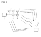
- FIG. 1 is a block diagram showing the structure of a communication system in accordance with the present embodiment.
- FIG. 1 shows that signals transmitted by a wireless transmitter 1 travel through a plurality of channels and arrive at a wireless receiver 7.
- the wireless transmitter 1 has a plurality of transmission antennas 2 to 4, and signals are sent from the respective transmission antennas 2 to 4 with different delay times, 0, T, and 2T applied to the respective transmission antennas.
- the wireless receiver 7 receives the signals transmitted from the wireless transmitter 1.
- FIG. 1 a case is described by way of example, in which the wireless transmitter 1 includes three transmission antennas 2 to 4.
- the plurality of transmission antennas mentioned here are, by way of example, the antennas installed in a wireless transmitter serving as a base station facility for cellular phones or the like, and can be any of three kinds of antenna namely; within the same sector, within the same base station but in different sectors, or in different base stations.
- the delay time T is applied by delay devices 5 and 6 in the figure, that apply a delay time ofT at transmission antenna 3, and a delay time of 2T at transmission antenna 4, as mentioned above.
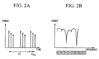
- FIG. 2A and FIG. 2B are diagrams showing the delay profile and transfer function of signal that reach the wireless receiver through a plurality of (three) channels with different delay times.
- FIG. 2A shows a delay profile in terms of time (horizontal axis) and power (vertical axis) of transmission signals that reach a wireless receiver through a plurality of channels with different delay times.
- the instantaneous delay profile has a maximum delayed wave of 2T + dmax, which is a greater maximum delayed wave than if the same signal were transmitted from the respective transmission antennas.
- dmax indicates the difference between the arrival times of the radio waves that traveled from the transmission antennas to the reception antenna over the fastest channel and those that traveled over slower channels.
- FIG. 2B shows a transfer function in terms of frequency (horizontal axis) and power (vertical axis) obtained by frequency-converting the delay profile in FIG. 2A .
- an increase in the maximum delay time 2T + dmax in the delay profile means more rapid variation in the transfer function due to frequency.
- data D1 and D2 are each spread at a spreading factor of four and subcarriers are allocated.
- the spreading factor or the coding rate of an error-correcting code is controlled on the wireless transmitter 1 side in accordance with the variation in the transfer function due to frequency.
- the spreading factor or code rate of the error-correcting code can be determined without regard to the variation of the channel due to frequency.
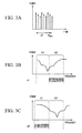
- FIG. 3A, FIG. 3B, and FIG. 3C are diagrams showing the delay profile and transfer function of signals that reach a wireless receiver through a plurality of channels with different delay times.
- FIG. 3A shows a delay profile in terms of time (horizontal axis) and power (vertical axis) which represents the arrival of transmission signals at a wireless receiver through a plurality of (three) channels with different delay times.
- FIG. 3B shows the transfer function at the wireless receiver used by user u1.
- FIG. 3C shows the transfer function at the wireless receiver used by user u2.
- the wireless receivers of user u1 and user u2 are at different locations, the instantaneous transfer functions are different. In other words, deeming the regions on the left side of FIG. 3B and FIG. 3C frequency channel b1, and the regions on the right side frequency channel b2, user u1 obtains better quality in frequency channel b2, and user u2 obtains better quality in frequency channel b1. Accordingly, the data D 1 to D4 are transmitted to user u 1 over frequency channel b2. The data D 1 to D4 are transmitted to user u2 over frequency channel b1.
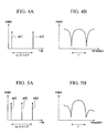
- FIG. 4A, FIG 4B, FIG. 5A, and FIG. 5B are diagrams showing the relationship between the maximum delay time (n - 1) T and frequency variation.
- the transfer function of this channel is as shown in FIG. 4B .
- a frequency diversity effect or a multi-user diversity effect can be obtained without being affected by the state of the channel.
- Transmission using frequency diversity and transmission using multi-user diversity can be switched in accordance with such factors as the type of signal being transmitted (pilot signal, control signal, broadcast/multicast signal or the like) or the speed at which the wireless receiver is moving (frequency diversity when the receiver is traveling quickly and multi-user diversity when the receiver is traveling slowly).
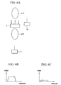
- FIG 6A through FIG. 6C are explanatory drawings showing the transmission of the same signal from multiple antennas of a wireless transmitter 8 without the application of delay time.
- the wireless transmitter 8 includes a plurality of (three) horizontally omnidirectional transmission antennas arranged in parallel
- the elliptical lobes e11 and e12 shown in FIG. 6A are produced, receivers in certain directions such as wireless receiver 9 are able to receive the reception signal across the entire frequency band with a high reception level (refer to FIG. 6B ), but receivers in other directions such as wireless receiver 10 receive the reception signal at a low reception level across the entire band (refer to FIG. 6C ).
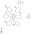
- FIG. 7A through FIG. 7C are explanatory drawings showing the transmission of the same signal from multiple antennas of the wireless transmitter 8, with different delay times applied.
- the wireless transmitter 8 includes a plurality of (three) horizontally omnidirectional transmission antennas arranged in parallel, and assuming a narrow band
- the elliptical lobes e21 to e26 shown in FIG. 7A are produced, certain frequency bands in the received signal have high reception levels and other frequency bands have low reception levels, but the average level of the received signal is fairly constant regardless of direction. Consequently, in terms of the reception level of the signals at the wireless receiver 9 (refer to FIG. 7B ) and at the wireless receiver 10 (refer to FIG.
- the method of transmitting signals by applying different delay times at respective antennas of the wireless transmitter 8 can overcome the deficiencies associated with transmitting the same signal from each of multiple antennas as explained with reference to FIG. 6A to FIG. 6C .
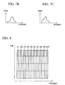
- FIG. 8 shows the signal structure within a chunk in the present embodiment.
- FIG. 8 shows the signal structure within the chunk K1 in FIG. 31 in detail.
- chunk K1 includes 19 subcarriers arranged in the frequency direction (horizontal axis direction) and four OFDM (Orthogonal Frequency Division Multiplexing) symbols arranged in the time direction (vertical axis).
- the shaded portions p1 to p10 in the figure constitute the Common Pilot Channel (CPICH), used to estimate the channel during demodulation and to measure aspects such as the quality of the received signal.
- CPICH Common Pilot Channel
- the foregoing structure is the same for chunks K1 to K20.
- the common pilot channel and dedicated pilot channel are referred to collectively as the pilot channels (the pilot channels in the claims).
- Delay time is added to the data signal portion only, not to the pilot channels.
- the dedicated pilot channel is added for the purpose of complementing the common pilot channel, and is used for such purposes as estimating channels during demodulation.
- the non-shaded portions in FIG. 8 are subcarriers which are allocated to the data signals used to carry data channels and control channels.
- FIG. 9 shows an example where orthogonal codes A, B, and C are allocated to the common pilot channel shown in FIG 8 .
- the common pilot channel is a pilot channel that is received at all terminals.
- the horizontal axis represents frequency
- the curved shapes at the top of the figure indicate subcarriers.
- the shaded subcarriers at the top of the figure correspond to the common pilot channel described in FIG. 8 , and orthogonal codes A, B, and C are allocated to this common pilot channel.
- the orthogonal codes are also allocated to every second subcarrier.
- the orthogonal codes (here orthogonal codes A, B, and C) are allocated, respectively, to the common pilot channel transmitted from each of the transmission antennas 2, 3, and 4 shown in FIG. 1 (hereinafter it is assumed that these antennas are allocated antenna number 1, 2, and 3 respectively). Consequently, for example if the common pilot channel transmitted from the transmission antenna 2 is multiplied by the orthogonal code A, then by multiplying the common pilot channels P1 to P4 by a complex conjugate of the orthogonal code A and adding the results, a transfer function that depicts the channel response in the frequency domain between the transmission antenna 2 and the reception antenna 11 can be determined even when the common pilot channels are transmitted concurrently from the other transmission antennas 3 and 4.
- the transfer function between the transmission antenna 2 (, the transmission antenna 3, or the transmission antenna 4) and the reception antenna 11 can be determined in the same manner.
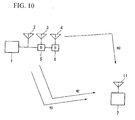
- FIG. 10 shows a simplified version of FIG. 1 .
- the two are the same in that signals are transmitted from a transmitter 1 through three transmission antennas 2, 3, and 4 and received at a receiver 7, but differ in that the transfer function of the channel between the transmission antenna 2 and the reception antenna 11 is labeled H1, the transfer function between the transmission antenna 3 and the reception antenna 11 is labeled H2, and the transfer function between the transmission antenna 4 and the reception antenna 7 is labeled H3.
- delay devices 5 and 6 add a delay of time T.
- the transmission signals transmitted from the transmitter 1 are presumed to reach the receiver 7 through a multi-path environment as shown in FIG. 1 , here for the sake of simplicity a single path environment is depicted. In the environment shown in FIG.
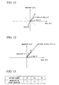
- the transfer function of the combined waves of the transmission antennas 2 to 4 for the received signals that reach the receiver 7 from the transmitter 1 can be expressed as in FIG. 11 , by taking into consideration the delay added by the delay devices 5 and 6 as well as the transfer functions H1 to H3.
- the horizontal axis is the real axis
- the vertical axis is the imaginary axis.
- m' is the subcarrier number of the middle subcarrier of the chunk used for communication between the transmitter 1 and the receiver 7 (for example chunk K1).
- Ts indicates the useful symbol duration of the OFDM symbol.
- ⁇ can be calculated once the chunk used for communication and the delay time T for each transmission antenna are determined, by utilizing the properties of the orthogonal codes to calculate the transfer functions H1 to H3 between the transmission antennas 2 to 4 and the reception antenna 8, H1, H2e j ⁇ , and H3e j2 ⁇ , which are the transfer functions after delay is added at each transmission antenna, and H1 + H2e j ⁇ + H3e j2 ⁇ , which is the transfer function after combining, can be calculated.
- the transfer functions H1, H2e j ⁇ , and H3e j2 ⁇ after delay is added at each transmission antenna can be calculated, then if, using for example H1 as a references, a vector of the transfer function after delay is added at each transmission antenna (here H3e j2 ⁇ ) appears in a position opposite H1 over a dashed straight line which passes through the origin and is perpendicular to H1, then it can be understood that the transmission antenna 4 is working so as to weaken the received signals. Accordingly, by transmitting a signal from the base station with the phase inverted at the transmission antenna 4, the signal from the transmission antenna 4 can be utilized so as to enhance the received signals as shown in FIG.
- the transfer functions H1, H2e j ⁇ , and H3e j2 ⁇ after delay is added at each transmission antenna can be measured only at the terminal apparatus, and phase control such as "inverting the phase of the transmission antenna 4" can be performed only at the base station, information about whether or not phase inversion is required for each antenna number is provided from the terminal apparatus to the base station in the form of a binary signal as shown in FIG. 13 .
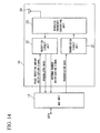
- the terminal apparatus includes: a MAC (Media Access Control) unit 17 that performs ARQ (Automatic Repeat reQuest) processing, scheduling processing, and data assembly and disassembly, as well as controlling a physical layer unit 18, including transferring data received from a higher layer (not shown) to the physical layer unit 18 and transferring data transferred from the physical layer unit 18 to the higher layer (not shown); the physical layer unit 18 that, under the control of the MAC unit 17, converts the transmission data transferred from the MAC unit 17 into a wireless transmission signal, and passes received wireless signals to the MAC unit 17.
- a MAC Media Access Control
- ARQ Automatic Repeat reQuest
- the MAC unit 17 notifies a reception circuit unit 22 of the phase rotation amount ⁇ shown in FIG. 11 and FIG. 12 , and the reception circuit 22 notifies the MAC unit 17 of obtained information about whether or not phase inversion is required for each antenna number ( FIG. 13 ) as an antenna number notification signal.
- the physical layer unit 18 includes: a transmission circuit unit 21 that modulates the transmission data notified from the MAC unit 17 and transfers to a wireless frequency converting unit 23; the reception circuit unit 22 that demodulates the output from the wireless frequency converting unit 23 and passes to the MAC unit 17; the wireless frequency converting unit 23 that converts transmission signals passed from the transmission circuit unit 21 into a wireless frequency, and converts reception signals received by an antenna unit 24 into a frequency band able to be processed by the reception circuit unit 22; and the antenna unit 24 that transmits transmission signals passed from the frequency converting unit 23, and receives signals.
- the fundamental roles of these constituent elements, with the exception of the reception circuit unit 22, are described in the following reference documents (1) and (2).
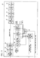
- the reception circuit 22 includes: an A/D converting unit 33 that performs analog/digital conversion of the output of the wireless frequency converting unit 23 ( FIG. 14 ); a GI removing unit 34 that removes a guard interval (GI) from the output of the A/D converting unit 33; an S/P converting unit 35 that performs serial/parallel conversion of the output of the GI removing unit 34; an FFT (Fast Fourier Transform) unit 36 that performs time/frequency conversion of the output of the S/P converting unit 35; a pilot channel extracting unit 37 that separates pilot channels from a data signal in the output of the FFT unit 36; antenna-specific channel estimating units 41-1 to 41-3 that use the pilot channels to derive the "transfer functions after delay is added at each transmission antenna" for the antennas numbered 1 to 3; an adding unit 44 that adds the outputs of the antenna-specific channel estimating units 41-1 to 41-3 for respective subcarriers;
- the antenna-specific channel estimating unit 41-1 includes: the channel estimating unit 42 that calculates a channel estimation value for each transmission antenna based on the pilot channel signal extracted from the received signal by the pilot channel extracting unit 37; and a phase rotating unit 43 that multiplies the output of the channel estimating unit 42 by an amount of phase rotation ⁇ m corresponding to the delay for each transmission antenna.
- An inversion antenna selecting unit 47 uses the outputs of the phase rotating unit 43 to determine which transmission antennas are to be subjected to phase rotation by a predetermined phase amount as shown in FIG. 11 and FIG. 12 (here, the predetermined phase amount is ⁇ , which inverts the phase), and notifies the MAC unit 17 of the result as the antenna number notification signal.
- the MAC unit 17 outputs this antenna number notification signal to the transmission circuit unit 21 ( FIG 14 ) as transmission data, and the data is then transmitted via the wireless frequency converting unit 23 and the antenna unit 24.
- the antenna-specific channel estimating units 41-2 and 41-3 have the same construction as the antenna-specific channel estimating unit 41-1. Furthermore, a situation in which the switch unit 45 uses the output of the channel estimating unit 42 as the channel estimation value corresponds to (for example) when a data signal is only transmitted from the transmission antenna allocated antenna number 1 (no transmission diversity is performed), and a situation in which the switch unit 45 uses the output of the adding unit 44 as the channel estimation value corresponds to (for example) when CDTD (Cyclic Delay Transmit Diversity) is performed.
- CDTD Cyclic Delay Transmit Diversity
- ⁇ m 2 ⁇ m (n - 1) T/Ts, where m is the subcarrier number, Ts is the useful symbol duration of the OFDM symbol, and (n - 1) T is the delay time applied to the transmission antenna allocated antenna number n. Furthermore, delay is added only to the data signal portion, not to the pilot channel.
- the reception circuit unit 22 shown in FIG. 16 has substantially the same construction as that shown in FIG. 15 , with the exception that the antenna-specific channel estimating unit 48-1 has an averaging unit 49.
- the inversion antenna selecting unit 47 uses the middle subcarrier of the chunk used for communication by the transmitter 1 and receiver 7 (for example chunk K1) as shown in FIG. 11 and FIG. 12 , but in FIG. 16 , the averaging unit 49 is provided that averages the outputs for multiple subcarriers from the phase rotating unit 43 calculated from the pilot channels in the chunk, and the inversion antenna selecting unit 47 uses the output of the averaging unit 49, and thus antennas can be selected using the average transfer function within the chunk.
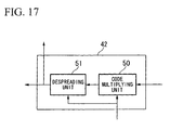
- FIG. 17 shows the channel estimating unit 42 of FIG. 15 and FIG. 16 in detail.
- the input to the channel estimating unit 42 enters a code multiplying unit 50.
- the input signal is multiplied by a complex conjugate of code A (refer to FIG. 9 ) in the code multiplying unit 50, and then added in a despreading unit 51 over the period of the orthogonal code (in the case of code A in FIG. 9 , adding for 4 pilot channels).
- the channel estimating unit 42 output can determine the transfer function of the channel from the desired antenna.
- Information about the orthogonal code and period thereof is notified from the control unit 46.
- FIG. 18 shows the construction of the base station apparatus.
- the base station apparatus includes: a PDCP (Packet Data Convergence Protocol) unit 65 that receives IP packets, performs such processing as compressing headers thereof, transfers to an RLC (Radio Link Control) unit 66, and decompresses the headers so as to convert data received from the RLC unit 66 into IP packets; the RLC (Radio Link Control) unit 66 that transfers data received from the PDCP unit 65 to a MAC (Media Access Control) unit 67 and also transfers data transferred from the MAC unit 67 to the PDCP unit 65; the MAC (Media Access Control) unit 67 that performs ARQ processing, scheduling processing, and data assembly and disassembly, as well as controlling a physical layer unit 68, transferring data transferred from the RLC unit 66 to the physical layer unit 68 and transferring data transferred from the physical layer unit 68 to the RLC unit 66; and the physical layer unit 68 that, under the control of the MAC unit 67,
- the MAC unit 67 includes: a scheduling unit 69 that determines the allocated slots to use to communicate with each terminal communicating with the base station apparatus; and a transmission circuit controlling unit 70 that controls the transmission circuit unit 71 using "subcarrier allocation information" based on "chunk allocation information" received from the scheduling unit 69, and uses a phase control signal to control the delay time between the antennas depending on a frequency diversity region or multi-user diversity region, as shown in FIG. 2 and FIG. 3 .
- the transmission circuit controlling unit 70 uses the antenna number notification signal, which is notified from the reception circuit 72 based on the received signal, to control the transmission circuit 71 through the phase control signal.
- the physical layer unit 68 includes: the transmission circuit unit 71 that performs modulation of data notified from the MAC unit 67 under the control of the transmission circuit controlling unit 70 and notifies the wireless frequency converting unit 73; the reception circuit unit 72 that demodulates the output of the wireless frequency converting unit 73 and passes to the MAC unit 67; the frequency converting unit 73 that converts transmission signals passed from the transmission circuit unit 71 into a wireless frequency, and converts reception signals received by antenna units 74 to 76 into a frequency band able to be processed by the reception circuit unit 72; and the antenna units 74 to 76 that transmit transmission signals passed from the frequency converting unit 73 into wireless space and receive signals from the wireless space.
- the transmission circuit unit 71 which is a feature of the present invention, the details of the roles of these constituent elements are described in reference documents (1) and (2) mentioned above, and detailed description thereof is omitted here.
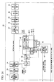
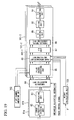
- FIG. 19 shows the construction of the transmission circuit unit 71 in the present embodiment.
- the transmission circuit unit 71 includes: user-specific signal processing units 81 a and 81 b that process signals destined for respective users; a pilot signal generating unit 102 that generates pilot channel signals which are used, for example, for channel estimation in the terminals, orthogonal codes which are orthogonal with each other being allocated to the respective antennas, and inputs them into a pilot channel inserting unit 85; a subcarrier allocating unit 84 that allocates the outputs of the user-specific signal processing units 81a and 81b to respective subcarriers; and antenna-specific signal processing units 101-1, 101-2, and 101-3 that process the signals for the respective antennas.
- the user-specific signal processing unit 81 a includes an error correction encoding unit 82 that performs error-correction encoding of transmission data, and a modulating unit 83 that performs modulation processing such as QPSK or 16 QAM on the output of the error correction encoding unit.
- the outputs from the user-specific signal processing units 81a and 81b are allocated to suitable subcarriers in the subcarrier allocating unit 84 which allocates to suitable subcarriers based on the "subcarrier allocation information" notified from the transmission circuit controlling unit 70 (refer to FIG. 18 ), and are then output to the antenna-specific signal processing units 101-1 to 101-3.
- the pilot channel inserting unit 85 allocates the output of the pilot channel generating unit 102 to the positions (subcarriers) for the common pilot channels as shown in FIG. 8 , based on the outputs of the subcarrier allocating unit 84 and the output of the pilot channel generating unit 102.
- the outputs of the pilot channel inserting unit 85 are input into a phase rotating/weight multiplying unit 86, in which a phase rotation ⁇ m or weight wm is multiplied for respective subcarriers, and the result is output to an IFFT (Inverse Fast Fourier Transport: inverse fast Fourier converting unit) unit 87. Then, the output of the IFFT unit 87 is subjected to parallel-to-serial conversion in a parallel/serial converting unit 88, and a guard interval is added to the output of the parallel/serial converting unit 88 by a GI adding unit 89.
- IFFT Inverse Fast Fourier Transport: inverse fast Fourier converting unit
- a filter unit 90 extracts only a signal of a desired bandwidth in the output of the GI adding unit 89, and a D/A converting unit 91 performs digital/analog conversion of the output of the filter unit 90 and outputs. This output serves as the output of the antenna-specific signal processing unit 101-1.
- the antenna-specific signal processing units 101-2 and 101-3 have a similar construction.
- the outputs of the antenna-specific signal processing units 101-1, 101-2, and 101-3 each pass through the wireless frequency converting unit 73 (refer to FIG. 18 ) which performs frequency-conversion into a wireless frequency and then output to the antennas 74, 75, and 76 (refer to FIG. 18 ) for transmission as a wireless signal.
- the phase rotating/weight multiplying unit 86 When phase rotation is added by the phase rotating/weight multiplying unit 86, the phase rotation is ⁇ m, which is notified from the transmission circuit controlling unit 70 as the phase control signal based on the antenna number notification signal included in the reception signal received by the base station apparatus. The details thereof will be described below.
- directivity control can be performed by setting the weight in the manner shown below.
- w m 1 n e 1 jk ⁇ ⁇ ⁇ sin ⁇ ° ⁇ 0 - n - 1 2 e 1 jk ⁇ ⁇ ⁇ sin ⁇ ° ⁇ 1 - n - 1 2 ... e jk ⁇ ⁇ ⁇ sin ⁇ ° ⁇ n - 1 - n - 1 2
- wm is the weight used by the weight multiplying circuit expressed as a vector, where the first element corresponds to the weight used for antenna number 1, the second element corresponds to the weight used for antenna number 2, and the nth element corresponds to the weight used for antenna number n, and so on.
- ⁇ ' is the direction of the main beam
- k is the ratio between the frequency at which the signal is to be transmitted and the frequency at which ⁇ ' was measured.
- ⁇ ' of the main beam a value measured by a receiver or the terminal of the other party of communication is notified to a weight calculating unit 310 and used when deriving the weight wm.
- the wm given above is only one example, and a method of deriving ⁇ ' and wm is proposed in detail in the following reference document:
- FIG. 20 relates to the phase control signal.
- different phase rotation is applied for respective antennas (antenna numbers 1, 2, and 3), respective subcarriers (subcarrier m), against the pilot channel and the data signal, and for respective chunks (or allocated slots) used for communication (the delay amount T differs as shown in FIG. 2 and FIG. 3 ).
- no delay amount is added to the pilot channel at any antenna, and no delay amount is added to the antenna designated antenna number 1.
- a delay time of T is added at antenna number 2 to the data signal portion only, and a delay time of 2T is added at antenna number 3.
- antenna number 3 is notified as shown in FIG 13 , and the phase inversion is performed for the antenna designated antenna number 3.
- the phase rotation amount ⁇ m of the phase control signal is always 0 for the pilot channel regardless of the antennas, and for the data signal portion, it is 0 for antenna number 1, 2 ⁇ mT/Ts for antenna number 2, and 2 ⁇ m2T/Ts+ ⁇ for antenna number 3.
- phase rotation is implemented based on the phase control signal. If the antenna number notification signal notified from the terminal indicates an antenna other than antenna number 3, the phase of that antenna is controlled by adding ⁇ .
- T is the delay time between antenna number 1 and antenna number 2, and can be a different value for respective chunks (or allocated slots) used for communication.
- m is the subcarrier number
- Ts is the useful symbol duration of the OFDM symbol.
- phase control information shown in FIG. 21 is used in the same manner.
- the phase control information in FIG. 21 is substantially the same as that in FIG. 20 , with the exception of the phase control information related to the pilot channel of antenna number 3.
- the phase inversion operation is performed in the phase rotating/weight multiplying unit 86 on not only the data signal but also the pilot channel of the antenna whose antenna number is included in the antenna number notification signal notified from the terminal, and the use of such phase control information distinguishes FIG. 21 from FIG. 20 .
- the phase rotation amount added in the phase rotating unit included in the antenna-specific channel estimating unit 41-3 on the terminal apparatus side in FIG. 15 also differs from FIG.
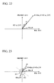
- FIG. 23 is substantially the same as FIG. 10 , except that by adding the phase rotation amount required to align the phases at H1, that is, adding phase rotation amount of ⁇ 2 to the signal H2e j ⁇ from the antenna designated antenna number 2 (in this case transmission antenna 3) and phase rotation amount of ⁇ 3 to the signal H3e j2 ⁇ from the antenna designated antenna number 3 (in this case transmission antenna 4), the received signals from the three transmission antennas can be added in an in-phase and received at the terminal.
- the terminal apparatus must notify the base station apparatus of the phase rotation amounts for respective antenna numbers as shown in FIG. 25 .
- FIG. 26 the apparatus configuration of the terminal apparatus of the present embodiment is shown in FIG. 26 .
- the terminal apparatus recited in FIG. 26 is substantially the same as that described in the first embodiment with reference to FIG. 14 , but differs in that the reception circuit unit 122 is different and an antenna number/phase rotation amount notification signal shown in FIG. 25 is notified from the reception circuit unit 122 to the MAC unit 17.
- the MAC unit 17 uses the antenna number/phase rotation amount notification signal as transmission data, the transmission circuit unit 21 performs modulation processing and performs communication with the base station.
- FIG. 27 is substantially the same as FIG.
- phase rotation amount calculating unit 147 calculates the phase rotation amount required to align the phases at respective antennas with the transfer function H1 as shown in FIG. 23 and FIG. 24 using the output of the phase rotating unit 43, and notifies the MAC unit 17 as the antenna number/phase rotation amount notification signal.
- the output of the averaging unit 49 can be input into the phase rotation amount calculating unit 147 in the same manner as in FIG. 16 of the first embodiment.
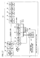
- FIG. 28 The construction of FIG. 28 is substantially the same as that of FIG. 18 of the first embodiment, but differs in that a transmission circuit controlling unit 170 controls the transmission circuit unit 71 using the antenna number/phase rotation amount notification signal notified from the reception circuit unit 72.
- the transmission circuit unit 71 is the same as that described in FIG. 19 , and will not be described in the present embodiment.
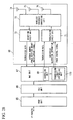
- the phase control information with which the transmission circuit controlling unit 170 controls the transmission circuit unit 71 can be expressed in the manner shown in FIG. 29.
- FIG. 29 is substantially the same as FIG.
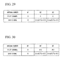
- phase control information shown in FIG. 30 could also be used.
- the phase control information in FIG. 30 is substantially the same as that in FIG. 29 , with the exception of the phase control information related to the pilot channels at antenna numbers 2 and 3.
- phase control is performed not only by phase control information related to the data signal included in the antenna number notification signal notified from the terminal, but also by phase control information related to the pilot channel of ⁇ 2 for antenna number 2 and ⁇ 3 for antenna number 3, the use of phase control information such as in FIG. 30 provides the distinction from FIG. 29 .
- the present invention is well suited to use in a communication system that performs multi-carrier transmission between a terminal apparatus and a base station apparatus and performs scheduling by dividing into multiple blocks in frequency and time domains, but is not limited to this.
Landscapes
- Engineering & Computer Science (AREA)
- Computer Networks & Wireless Communication (AREA)
- Signal Processing (AREA)
- Computer Security & Cryptography (AREA)
- Radio Transmission System (AREA)
- Mobile Radio Communication Systems (AREA)
- Transmitters (AREA)
- Arrangements For Transmission Of Measured Signals (AREA)
- Burglar Alarm Systems (AREA)
- Input Circuits Of Receivers And Coupling Of Receivers And Audio Equipment (AREA)
- Radar Systems Or Details Thereof (AREA)
- Maintenance And Management Of Digital Transmission (AREA)
Claims (19)
- Endgerätvorrichtung, die in einem Kommunikationssystem vorgesehen ist, in dem eine Basisstationsvorrichtung zu jeweiligen Unterträgern eine Phasendrehung hinzufügt, wobei die Endgerätvorrichtung gekennzeichnet ist durch:eine Kanalschätzeinheit (42), die Signale von Steuerkanälen bzw. Pilotkanälen empfängt, die jeweiligen Basisstationsantennen (2-4) zugeordnet sind und zueinander orthogonal sind, und Kanäle mit den jeweiligen Basisstationsantennen anhand der Signale der Steuerkanäle bzw. Pilotkanäle schätzt;eine Antennenauswahl-/Phasenbetragberechnungs-Einheit (47, 147), die eine Auswahl einer Basisstationsantenne oder eine Berechnung von Phasendrehbeträgen der Basisstationsantennen anhand eines Ergebnisses der Kanalschätzung durch die Kanalschätzeinheit ausführt; undeine Sendeeinheit (17, 21, 23, 24), die eine Kennung der Basisstationsantenne, die durch die Antennenauswahl-/Phasenbetragberechnungs-Einheit ausgewählt wird, oder die Phasendrehbeträge, die durch die Antennenauswahl-/Phasenbetragberechnungs-Einheit berechnet werden, sendet.
- Endgerätvorrichtung nach Anspruch 1, ferner mit einer Phasendreheinheit (43), die die Phase des Ergebnisses der Kanalschätzung durch die Kanalschätzeinheit um einen vorgegebenen Betrag für die jeweiligen Basisstationsantennen dreht,
wobei die Antennenauswahl-/Phasenbetragberechnungs-Einheit anhand eines Ausgangs der Phasendreheinheit die Basisstationsantenne auswählt oder die Phasendrehbeträge der Basisstation berechnet. - Endgerätvorrichtung nach Anspruch 1, wobei die Kanalschätzeinheit die Steuerkanäle bzw. Pilotkanäle empfängt, die aufgrund von orthogonalen Codes, die den jeweiligen Basisstationsantennen zugewiesen sind, zueinander orthogonal sind, und eine Kanalschätzung mit den Basisstationsantennen anhand der Signale der Steuerkanäle bzw. Pilotkanäle ausführt.
- Endgerätvorrichtung nach Anspruch 1, wobei die Antennenauswahl-/Phasenbetragberechnungs-Einheit eine Basisstationsantenne, die einer Phasendrehung um einen vorgegebenen Phasenbetrag θ (0 ≤ θ < 2π) unterworfen werden soll, anhand eines Ausgangs der Phasendreheinheit auswählt und
die Sendeeinheit die Kennung der Basisstationsantenne, die durch die Antennenauswahl-/Phasenbetragsberechnungs-Einheit ausgewählt wird, sendet. - Endgerätvorrichtung nach Anspruch 4, wobei der vorgegebene Phasenbetrag θ gleich π ist.
- Endgerätvorrichtung nach Anspruch 1, wobei die Antennenauswahl-/Phasenbetragberechnungs-Einheit eine Basisstationsantenne auswählt und einen Phasendrehbetrag der ausgewählten Basisstationsantenne berechnet und die Sendeeinheit die Kennung der durch die Antennenauswahl-/Phasenbetragberechnungs-Einheit ausgewählten Basissitationsantenne und den Phasendrehbetrag, der durch die Antennenauswahl-/Phasenbetragberechnungs-Einheit berechnet wird, sendet.
- Endgerätvorrichtung nach Anspruch 1, wobei die Antennenauswahl-/Phasenbetragberechnungs-Einheit anhand eines Durchschnittswerts von Ausgängen von der Phasendreheinheit für mehrere Unterträger den Phasendrehbetrag berechnet oder die Antenne auswählt.
- Basisstatiorisvorrichtung, die eine Phasendreheinheit (86) enthält, die auf jeweilige Unterträger eine Phasendrehung anwendet,
dadurch gekennzeichnet, dass die Basisstationsvorrichtung ferner enthält:eine Sendeeinheit (102, 85, 71, 73), die Signale von Steuerkanälen bzw. Pilotkanälen, die jeweiligen Basisstationsantennen (74-76) zugewiesen sind und zueinander orthogonal sind, sendet; undeine Sendeschaltungs-Steuereinheit (70), die eine Phasensteuerung für die jeweiligen Basisstationsantennen anhand einer Kennung einer Basisstationsantenne oder eines Phasendrehbetrags, die in einem empfangenen Signal enthalten sind, richtet,wobei die Phasendreheinheit die Phasendrehung auf jeweilige Unterträger anhand einer Richtung von der Sendeschaltungs-Steuereinheit anwendet. - Basisstationsvorrichtung nach Anspruch 8, wobei die Sendeeinheit die Signale der Steuerkanäle bzw. Pilotkanäle sendet, die aufgrund von orthogonalen Codes, die den jeweiligen Basisstationsantennen zugewiesen sind, zueinander orthogonal sind.
- Basisstationsvorrichtung nach Anspruch 8, wobei die Phasendreheinheit zu Unterträgern, die den Steuerkanälen bzw. Pilotkanälen entsprechen, keine Phasendrehung hinzufügt und zu einem Unterträger, der einem Datensignal entspricht, sowohl eine Phasendrehung in Übereinstimmung mit Verzögerungszeiten, die zu jeweiligen Antennen hinzugefügt worden sind, als auch eine Phasendrehung auf der Grundlage der Richtung von der Sendeschaltungs-Steuereinheit hinzufügt.
- Basisstationsvorrichtung nach Anspruch 8, wobei die Phasendreheinheit zu Unterträgern, die den Steuerkanälen bzw. Pilotkanälen entsprechen, anhand der Richtung von der Sendeschaltungs-Steuereinheit eine Phasendrehung hinzufügt und zu einem Unterträger, der einem Datensignal entspricht, sowohl eine Phasendrehung in Übereinstimmung mit Verzögerungszeiten, die zu jeweiligen Antennen hinzugefügt worden sind, als auch eine Phasendrehung anhand der Richtung von der Sendeschaltungs-Steuereinheit hinzufügt.
- Basisstationsvorrichtung nach Anspruch 8, wobei die Phasendreheinheit zu Unterträgern, die den Steuerkanälen bzw. Pilotkanälen entsprechen, in Übereinstimmung mit Verzögerungszeiten, die zu den jeweiligen Antennen hinzugefügt worden sind, eine Phasendrehung hinzufügt und zu einem Unterträger, der einem Datensignal entspricht, sowohl eine Phasendrehung in Übereinstimmung mit einer den jeweiligen Antennen hinzugefügten Verzögerungszeit als auch eine Phasendrehung anhand der Richtung von der Sendeschaltungs-Steuereinheit hinzufügt.
- Basisstationsvorrichtung nach Anspruch 8, wobei das empfangene Signal keinen Phasendrehbetrag enthält und
die Sendeschaltungs-Steuereinheit die Phasendrehung für die jeweiligen Basisstationsantennen anhand der Kennung der Basisstationsantenne, die in dem empfangenen Signal enthalten ist, und eines vorgegebenen Phasenbetrags θ (0 s θ < 2π), der ein den jeweiligen Unterträgern gemeinsamer Wert ist, richtet. - Basisstationsvorrichtung nach Anspruch 13, wobei der vorgegebene Phasenbetrag θ gleich π ist.
- Basisstationsvorrichtung nach Anspruch 8, wobei die Verzögerungszeiten, die zu den jeweiligen Basisstationsantennen hinzugefügt werden, für Endgerätvorrichtungen, die mit der Basisstationsvorrichtung kommunizieren, auf unterschiedliche Werte gesetzt werden können.
- Kommunikationssystem, mit:der Endgerätvorrichtung nach Anspruch 1; undder Basisstationsvorrichtung nach Anspruch 8, die mit der Endgerätvorrichtung durch eine drahtlose Kommunikationsleitung verbunden ist.
- Kommunikationssystem, mit:der Endgerätvorrichtung nach Anspruch 4; undder Basisstationsvorrichtung nach Anspruch 13, die mit der Endgerätvorrichtung über eine drahtlose Kommunikationsleitung verbunden ist.
- Kommunikationssystem, mit:der Endgerätvorrichtung nach Anspruch 5; undder Basisstationsvorrichtung nach Anspruch 14, die mit der Endgerätvorrichtung über eine drahtlose Kommunikationsleitung verbunden ist.
- Kommunikationssystem, mit;der Endgerätvorrichtung nach Anspruch 6; undder Basisstationsvorrichtung nach einem der Ansprüche 10 bis 12, die mit der Endgerätvorrichtung über eine drahtlose Kommunikationsleitung verbunden ist.
Priority Applications (6)
| Application Number | Priority Date | Filing Date | Title |
|---|---|---|---|
| PL08021641T PL2034624T3 (pl) | 2005-10-31 | 2006-10-30 | Nadajnik bezprzewodowy |
| EP20080021642 EP2034625B1 (de) | 2005-10-31 | 2006-10-30 | Drahtloser Sender |
| EP20080021643 EP2037592B1 (de) | 2005-10-31 | 2006-10-30 | Drahtloser Empfänger |
| PL06822565T PL1944882T3 (pl) | 2005-10-31 | 2006-10-30 | Urządzenie terminala, urządzenie stacji bazowej i system komunikacyjny |
| EP20080021641 EP2034624B1 (de) | 2005-10-31 | 2006-10-30 | Drahtloser Sender |
| PL08021643T PL2037592T3 (pl) | 2005-10-31 | 2006-10-30 | Odbiornik bezprzewodowy |
Applications Claiming Priority (2)
| Application Number | Priority Date | Filing Date | Title |
|---|---|---|---|
| JP2005316549 | 2005-10-31 | ||
| PCT/JP2006/321608 WO2007052576A1 (ja) | 2005-10-31 | 2006-10-30 | 端末装置、基地局装置および通信システム |
Related Child Applications (6)
| Application Number | Title | Priority Date | Filing Date |
|---|---|---|---|
| EP20080021641 Division EP2034624B1 (de) | 2005-10-31 | 2006-10-30 | Drahtloser Sender |
| EP20080021643 Division EP2037592B1 (de) | 2005-10-31 | 2006-10-30 | Drahtloser Empfänger |
| EP20080021642 Division EP2034625B1 (de) | 2005-10-31 | 2006-10-30 | Drahtloser Sender |
| EP08021643.5 Division-Into | 2008-12-12 | ||
| EP08021642.7 Division-Into | 2008-12-12 | ||
| EP08021641.9 Division-Into | 2008-12-12 |
Publications (3)
| Publication Number | Publication Date |
|---|---|
| EP1944882A1 EP1944882A1 (de) | 2008-07-16 |
| EP1944882A4 EP1944882A4 (de) | 2010-03-10 |
| EP1944882B1 true EP1944882B1 (de) | 2011-03-02 |
Family
ID=38005728
Family Applications (4)
| Application Number | Title | Priority Date | Filing Date |
|---|---|---|---|
| EP20080021643 Active EP2037592B1 (de) | 2005-10-31 | 2006-10-30 | Drahtloser Empfänger |
| EP20060822565 Active EP1944882B1 (de) | 2005-10-31 | 2006-10-30 | Endgerätevorrichtung, basisstationsvorrichtung und kommunikationssystem |
| EP20080021642 Active EP2034625B1 (de) | 2005-10-31 | 2006-10-30 | Drahtloser Sender |
| EP20080021641 Active EP2034624B1 (de) | 2005-10-31 | 2006-10-30 | Drahtloser Sender |
Family Applications Before (1)
| Application Number | Title | Priority Date | Filing Date |
|---|---|---|---|
| EP20080021643 Active EP2037592B1 (de) | 2005-10-31 | 2006-10-30 | Drahtloser Empfänger |
Family Applications After (2)
| Application Number | Title | Priority Date | Filing Date |
|---|---|---|---|
| EP20080021642 Active EP2034625B1 (de) | 2005-10-31 | 2006-10-30 | Drahtloser Sender |
| EP20080021641 Active EP2034624B1 (de) | 2005-10-31 | 2006-10-30 | Drahtloser Sender |
Country Status (11)
| Country | Link |
|---|---|
| US (7) | US20100130221A1 (de) |
| EP (4) | EP2037592B1 (de) |
| JP (5) | JP4503650B2 (de) |
| CN (4) | CN101483465B (de) |
| AT (3) | ATE540487T1 (de) |
| DE (1) | DE602006020477D1 (de) |
| EA (4) | EA016947B1 (de) |
| ES (3) | ES2378714T3 (de) |
| HK (3) | HK1130127A1 (de) |
| PL (3) | PL2037592T3 (de) |
| WO (1) | WO2007052576A1 (de) |
Families Citing this family (31)
| Publication number | Priority date | Publication date | Assignee | Title |
|---|---|---|---|---|
| CN101729118B (zh) * | 2005-09-01 | 2016-03-23 | 施耐普特拉克股份有限公司 | 发送控制方法 |
| CN102324956B (zh) * | 2005-10-31 | 2015-01-14 | 夏普株式会社 | 无线发射机、无线通信系统及无线发送方法 |
| EP2037592B1 (de) * | 2005-10-31 | 2012-01-04 | Sharp Kabushiki Kaisha | Drahtloser Empfänger |
| DK2120365T3 (da) * | 2005-12-20 | 2012-05-29 | Sharp Kk | Fremgangsmåde til transmissionsstyring, basisstation, mobil enhed og kommunikationssystem til forsinkelsesdiversitet |
| JP4658146B2 (ja) * | 2005-12-26 | 2011-03-23 | シャープ株式会社 | 無線送信機及び無線送信方法 |
| TWI333342B (en) * | 2006-11-06 | 2010-11-11 | Inst Information Industry | Signal relay apparatus, method, application program, and computer readable medium capable of adjusting amplifying gain dynamicaaly |
| GB2449470B (en) * | 2007-05-23 | 2011-06-29 | British Broadcasting Corp | OFDM-MIMO radio frequency transmission system |
| WO2010060453A1 (en) * | 2008-11-03 | 2010-06-03 | Nokia Corporation | Methods, apparatuses and computer program products for transmission diversity |
| US20100111145A1 (en) * | 2008-11-05 | 2010-05-06 | Broadcom Corporation | Baseband unit having bit repetitive encoded/decoding |
| TWI482745B (zh) | 2008-11-26 | 2015-05-01 | Asahi Glass Co Ltd | A glass member having a sealing material layer, and an electronic device using the same, and a method of manufacturing the same |
| JP5167097B2 (ja) * | 2008-12-03 | 2013-03-21 | 株式会社エヌ・ティ・ティ・ドコモ | 信号生成装置及び信号生成方法 |
| JP5392268B2 (ja) * | 2009-01-05 | 2014-01-22 | 富士通株式会社 | 通信装置、移動局および通信制御方法 |
| WO2010085069A2 (en) * | 2009-01-20 | 2010-07-29 | Lg Electronics Inc. | Method and apparatus for channel access in contention-based communication system and station |
| JP5410812B2 (ja) * | 2009-03-31 | 2014-02-05 | 三星電子株式会社 | 無線通信装置、無線通信システム、及び直接波の受信タイミング検出方法 |
| US20100329370A1 (en) * | 2009-04-28 | 2010-12-30 | Beceem Communications Inc. | Selection of a Subset of Antennas for Transmission |
| JP5278173B2 (ja) * | 2009-06-04 | 2013-09-04 | ソニー株式会社 | 受信装置および方法、プログラム、並びに受信システム |
| US8224261B2 (en) * | 2009-08-24 | 2012-07-17 | Arvind Vijay Keerthi | Creation of a beam using antennas |
| CN102377466B (zh) * | 2010-08-13 | 2014-04-30 | 华为技术有限公司 | 多天线分集调度方法和装置 |
| US8483735B2 (en) * | 2010-08-26 | 2013-07-09 | Telefonaktiebolaget L M Ericsson (Publ) | Methods and apparatus for parallel scheduling of frequency resources for communication nodes |
| US8817912B1 (en) * | 2010-10-27 | 2014-08-26 | Marvell International Ltd. | Phase-rotated tone-grouping modulation |
| CN107659351B (zh) | 2011-02-18 | 2021-07-06 | 太阳专利托管公司 | 发送、接收的方法和装置 |
| US9401791B2 (en) * | 2011-05-10 | 2016-07-26 | Lg Electronics Inc. | Method for transmitting signal using plurality of antenna ports and transmission end apparatus for same |
| KR20120138169A (ko) * | 2011-06-14 | 2012-12-24 | 삼성전자주식회사 | 무선 통신 시스템에서 신호 수신 장치 및 방법 |
| US8861638B2 (en) * | 2011-09-26 | 2014-10-14 | Cambridge Silicon Radio Limited | Transmitter with reduced peak-to-mean amplitude ratio |
| TW201317573A (zh) * | 2011-10-31 | 2013-05-01 | Ind Tech Res Inst | 多通道裝置及其硬體相位偏移修正方法 |
| US8805394B2 (en) | 2012-05-17 | 2014-08-12 | Intel Corporation | Systems and methods for interference mitigation in heterogeneous networks |
| US9871565B2 (en) * | 2013-03-01 | 2018-01-16 | Sony Corporation | MIMO communication method, transmitting device, and receiving device |
| JP2015076700A (ja) * | 2013-10-08 | 2015-04-20 | 株式会社Nttドコモ | 無線装置、無線制御装置及び通信制御方法 |
| CN112187329A (zh) * | 2015-10-08 | 2021-01-05 | 松下电器(美国)知识产权公司 | 发送方法、发送装置、接收方法、接收装置 |
| KR102514061B1 (ko) * | 2018-01-17 | 2023-03-24 | 삼성전자주식회사 | 무선 통신 시스템에서 신호를 송수신하는 방법 및 장치 |
| JP6723424B1 (ja) * | 2019-06-21 | 2020-07-15 | 株式会社横須賀テレコムリサーチパーク | 送受信方法および送受信システム |
Family Cites Families (81)
| Publication number | Priority date | Publication date | Assignee | Title |
|---|---|---|---|---|
| US266354A (en) * | 1882-10-24 | Caspar dickhaut | ||
| US137948A (en) * | 1873-04-15 | Improvement in extension-ladders | ||
| EP0232626B1 (de) * | 1985-12-26 | 1993-02-10 | Matsushita Electric Industrial Co., Ltd. | Übertragungsmethode eines digitalen Signals mit verbesserten Fehlerrateeigenschaften bei Mehrwegübertragung |
| JPH0834631B2 (ja) * | 1989-12-28 | 1996-03-29 | 日本電気株式会社 | デジタル移動通信システム |
| JPH04347410A (ja) | 1991-05-24 | 1992-12-02 | Matsushita Electric Ind Co Ltd | 燃焼器の着火制御装置 |
| DE69705356T2 (de) * | 1996-05-17 | 2002-05-02 | Motorola Ltd., Basingstoke | Verfahren und Vorrichtung zur Gewichtung eines Uebertragungsweges |
| US6034987A (en) * | 1996-12-17 | 2000-03-07 | Ericsson Inc. | System for improving the quality of a received radio signal |
| US6160510A (en) * | 1997-07-03 | 2000-12-12 | Lucent Technologies, Inc. | Delay line antenna array system and method thereof |
| US6131016A (en) * | 1997-08-27 | 2000-10-10 | At&T Corp | Method and apparatus for enhancing communication reception at a wireless communication terminal |
| SE513656C2 (sv) * | 1997-11-21 | 2000-10-16 | Ericsson Telefon Ab L M | Förfarande och anordning för mottagning av radiosignaler med hjälp av antennlober |
| JP3718337B2 (ja) * | 1998-01-08 | 2005-11-24 | 株式会社東芝 | 適応可変指向性アンテナ |
| US5986972A (en) * | 1998-03-31 | 1999-11-16 | The United States Of America As Represented By The Secretary Of The Navy | Beam pattern shaping for transmitter array |
| EP1011167A4 (de) * | 1998-07-02 | 2005-10-12 | Matsushita Electric Ind Co Ltd | Antenneneinheit, kommunikationssystem und digitaler fernsehempfänger |
| KR100316777B1 (ko) * | 1999-08-24 | 2001-12-12 | 윤종용 | 차세대 이동 통신 시스템에서의 폐쇄 루프 전송 안테나 다이버시티 방법 및 이를 위한 기지국 장치 및 이동국 장치 |
| JP3732364B2 (ja) * | 1999-08-27 | 2006-01-05 | 松下電器産業株式会社 | 通信端末装置及びチャネル推定方法 |
| JP2001168777A (ja) * | 1999-12-06 | 2001-06-22 | Matsushita Electric Ind Co Ltd | 通信端末装置及び無線通信方法 |
| US6807145B1 (en) * | 1999-12-06 | 2004-10-19 | Lucent Technologies Inc. | Diversity in orthogonal frequency division multiplexing systems |
| JP4495288B2 (ja) * | 2000-01-18 | 2010-06-30 | パナソニック株式会社 | 基地局装置、通信端末装置、及び無線通信方法 |
| US6377632B1 (en) | 2000-01-24 | 2002-04-23 | Iospan Wireless, Inc. | Wireless communication system and method using stochastic space-time/frequency division multiplexing |
| JP4187377B2 (ja) * | 2000-02-23 | 2008-11-26 | 富士通株式会社 | 無線送受信機及び電波放射方向制御方法 |
| US7139324B1 (en) * | 2000-06-02 | 2006-11-21 | Nokia Networks Oy | Closed loop feedback system for improved down link performance |
| WO2002007341A2 (en) * | 2000-07-14 | 2002-01-24 | Ip.Access Ltd. | Cellular radio telecommunication system |
| US6731619B1 (en) * | 2000-08-02 | 2004-05-04 | Ericsson Inc. | Method and system for using one type of transmit diversity in a first time slot and a second type in an adjacent time slot |
| FR2813465B1 (fr) * | 2000-08-29 | 2005-04-08 | Mitsubishi Electric Inf Tech | Methode d'estimation conjointe de canal et de direction d'arrivee |
| US7065156B1 (en) * | 2000-08-31 | 2006-06-20 | Nokia Mobile Phones Ltd. | Hopped delay diversity for multiple antenna transmission |
| US6842487B1 (en) * | 2000-09-22 | 2005-01-11 | Telefonaktiebolaget Lm Ericsson (Publ) | Cyclic delay diversity for mitigating intersymbol interference in OFDM systems |
| JP3639521B2 (ja) * | 2000-11-10 | 2005-04-20 | 株式会社ケンウッド | ダイバーシティ受信機及び直交周波数分割多重信号受信方法 |
| KR100353641B1 (ko) * | 2000-12-21 | 2002-09-28 | 삼성전자 주식회사 | 부호분할다중접속 이동통신시스템의 기지국 전송 안테나다이버시티 장치 및 방법 |
| JP4496673B2 (ja) * | 2001-06-07 | 2010-07-07 | 株式会社デンソー | Ofdm方式の送受信機 |
| US7440509B2 (en) * | 2001-06-21 | 2008-10-21 | Motorola, Inc. | Method and system for interference averaging in a wireless communication system |
| US6550910B2 (en) * | 2001-08-16 | 2003-04-22 | Hewlett-Packard Company | Imaging device with interface features |
| JP4308655B2 (ja) * | 2001-09-14 | 2009-08-05 | 富士通株式会社 | 移動通信システム,移動局及び基地局 |
| US7164649B2 (en) * | 2001-11-02 | 2007-01-16 | Qualcomm, Incorporated | Adaptive rate control for OFDM communication system |
| US7149258B2 (en) * | 2001-11-28 | 2006-12-12 | Telefonaktiebolaget L M Ericsson (Publ) | Method and apparatus for estimation of phase offset between communication channels |
| DE60217464T2 (de) * | 2002-02-07 | 2007-11-15 | Mitsubishi Denki K.K. | Kanal- und Verzögerungsschätzung in Mehrträgersystemen |
| US7116944B2 (en) * | 2002-02-07 | 2006-10-03 | Lucent Technologies Inc. | Method and apparatus for feedback error detection in a wireless communications systems |
| JP3640185B2 (ja) * | 2002-02-13 | 2005-04-20 | 日本電気株式会社 | マルチキャリア通信方式のサブキャリア間干渉低減方法及びそれを用いた受信機 |
| US6862456B2 (en) * | 2002-03-01 | 2005-03-01 | Cognio, Inc. | Systems and methods for improving range for multicast wireless communication |
| EP1570589A1 (de) * | 2002-12-04 | 2005-09-07 | Koninklijke Philips Electronics N.V. | Verz gerungsdiversity in einem drahtlosen kommunikationssystem |
| KR100605860B1 (ko) * | 2003-01-09 | 2006-07-31 | 삼성전자주식회사 | 4개의 송신 안테나를 사용하는 무선통신 시스템의 송신 장치 및 방법 |
| US7406335B2 (en) * | 2003-01-13 | 2008-07-29 | Lucent Technologies Inc. | Multiple antenna transmissions with deterministic phase differences |
| JP2004320168A (ja) * | 2003-04-11 | 2004-11-11 | Matsushita Electric Ind Co Ltd | 無線受信装置および無線受信方法 |
| FI20030777A0 (fi) * | 2003-05-22 | 2003-05-22 | Nokia Corp | Lähetysdiversiteetin kertaluvun ja lähetyshaarojen määritys |
| US7438903B2 (en) * | 2003-06-06 | 2008-10-21 | Nbty, Inc. | Methods and compositions that enhance bioavailability of coenzyme-Q10 |
| MXPA05013784A (es) * | 2003-06-16 | 2006-02-28 | Sherwin Williams Co | Composiciones de recubrimiento de alta consistencia. |
| US7257408B2 (en) * | 2003-06-30 | 2007-08-14 | Nec Corporation | Radio communication system and transmission mode selecting method |
| US20050048933A1 (en) * | 2003-08-25 | 2005-03-03 | Jingxian Wu | Adaptive transmit diversity with quadrant phase constraining feedback |
| US7242722B2 (en) * | 2003-10-17 | 2007-07-10 | Motorola, Inc. | Method and apparatus for transmission and reception within an OFDM communication system |
| KR100557158B1 (ko) | 2003-11-12 | 2006-03-03 | 삼성전자주식회사 | 직교 주파수 분할 다중 방식을 사용하는 이동통신시스템에서 부반송파 할당을 위한 장치 및 방법 |
| US8040986B2 (en) * | 2003-11-26 | 2011-10-18 | Texas Instruments Incorporated | Frequency-domain subchannel transmit antenna selection and power pouring for multi-antenna transmission |
| KR100507541B1 (ko) | 2003-12-19 | 2005-08-09 | 삼성전자주식회사 | 직교주파수분할다중접속 시스템에서의 데이터 및 파일롯할당 방법 과 그를 이용한 송신 방법 및 그 장치, 수신방법과 그 장치 |
| JP2005191997A (ja) | 2003-12-26 | 2005-07-14 | Sanyo Electric Co Ltd | 受信方法および装置 |
| US7742533B2 (en) * | 2004-03-12 | 2010-06-22 | Kabushiki Kaisha Toshiba | OFDM signal transmission method and apparatus |
| JP2005259030A (ja) * | 2004-03-15 | 2005-09-22 | Sharp Corp | 性能評価装置、性能評価方法、プログラムおよびコンピュータ読取可能記録媒体 |
| JP4290048B2 (ja) * | 2004-03-23 | 2009-07-01 | 三洋電機株式会社 | 受信方法および装置 |
| US7447268B2 (en) | 2004-03-31 | 2008-11-04 | Intel Corporation | OFDM system with per subcarrier phase rotation |
| JP2005316549A (ja) | 2004-04-27 | 2005-11-10 | Omron Corp | セキュリティシステムおよび防犯方法 |
| US8331377B2 (en) * | 2004-05-05 | 2012-12-11 | Qualcomm Incorporated | Distributed forward link schedulers for multi-carrier communication systems |
| FR2870406A1 (fr) * | 2004-05-14 | 2005-11-18 | St Microelectronics Sa | Modulation de charge d'un transporteur |
| US8233555B2 (en) * | 2004-05-17 | 2012-07-31 | Qualcomm Incorporated | Time varying delay diversity of OFDM |
| JP4515155B2 (ja) * | 2004-05-25 | 2010-07-28 | 株式会社エヌ・ティ・ティ・ドコモ | 送信装置 |
| US8089855B2 (en) * | 2004-06-04 | 2012-01-03 | Qualcomm Incorporated | Transmission of overhead information for broadcast and multicast services in a wireless communication system |
| KR20050118031A (ko) | 2004-06-12 | 2005-12-15 | 삼성전자주식회사 | 순환지연 다이버시티를 이용하여 방송 채널을 효율적으로전송하는 장치 및 방법 |
| TWI246273B (en) * | 2004-06-28 | 2005-12-21 | Ind Tech Res Inst | Method and apparatus for high-order PAPR reduction of an OFDM signal |
| US7676007B1 (en) * | 2004-07-21 | 2010-03-09 | Jihoon Choi | System and method for interpolation based transmit beamforming for MIMO-OFDM with partial feedback |
| US7319868B2 (en) * | 2004-09-27 | 2008-01-15 | Telefonktiebolaget Lm Ericsson (Publ) | Derivation of optimal antenna weights during soft handover |
| US7436903B2 (en) * | 2004-09-29 | 2008-10-14 | Intel Corporation | Multicarrier transmitter and method for transmitting multiple data streams with cyclic delay diversity |
| CN103236876B (zh) * | 2005-01-17 | 2016-08-10 | 夏普株式会社 | 发送装置及方法、接收装置及方法、以及通信系统 |
| US7953039B2 (en) * | 2005-04-21 | 2011-05-31 | Samsung Elecronics Co., Ltd. | System and method for channel estimation in a delay diversity wireless communication system |
| US7634290B2 (en) * | 2005-05-31 | 2009-12-15 | Vixs Systems, Inc. | Adjusting transmit power of a wireless communication device |
| US7738356B2 (en) * | 2005-06-28 | 2010-06-15 | Broadcom Corporation | Multiple stream cyclic-shifted delay transmitter |
| US20070004465A1 (en) * | 2005-06-29 | 2007-01-04 | Aris Papasakellariou | Pilot Channel Design for Communication Systems |
| AU2006203697A1 (en) * | 2005-08-26 | 2007-03-15 | Nec Australia Pty Ltd | Adaptive pilot structure to assist channel estimation in spread spectrum systems |
| CN101729118B (zh) * | 2005-09-01 | 2016-03-23 | 施耐普特拉克股份有限公司 | 发送控制方法 |
| US8139672B2 (en) * | 2005-09-23 | 2012-03-20 | Qualcomm Incorporated | Method and apparatus for pilot communication in a multi-antenna wireless communication system |
| KR100831177B1 (ko) * | 2005-10-08 | 2008-05-21 | 삼성전자주식회사 | 스마트 안테나 통신시스템의 송신기 및 송신 방법 |
| EP2148482A1 (de) | 2005-10-28 | 2010-01-27 | Sharp Kabushiki Kaisha | OFDM-Sender mit Unterträgergruppen-Phasenverschiebung und entsprechender Empfänger |
| EP2037592B1 (de) * | 2005-10-31 | 2012-01-04 | Sharp Kabushiki Kaisha | Drahtloser Empfänger |
| US8233552B2 (en) * | 2005-11-07 | 2012-07-31 | Broadcom Corporation | Method and system for utilizing givens rotation expressions for asymmetric beamforming matrices in explicit feedback information |
| US7672388B2 (en) * | 2006-03-23 | 2010-03-02 | Motorola, Inc. | Method of providing signal diversity in an OFDM system |
| US8213541B2 (en) * | 2006-09-12 | 2012-07-03 | Hera Wireless S.A. | Receiving method for receiving signals by a plurality of antennas, and a receiving apparatus and a radio apparatus using the same |
-
2006
- 2006-10-30 EP EP20080021643 patent/EP2037592B1/de active Active
- 2006-10-30 EP EP20060822565 patent/EP1944882B1/de active Active
- 2006-10-30 EP EP20080021642 patent/EP2034625B1/de active Active
- 2006-10-30 PL PL08021643T patent/PL2037592T3/pl unknown
- 2006-10-30 PL PL06822565T patent/PL1944882T3/pl unknown
- 2006-10-30 ES ES08021643T patent/ES2378714T3/es active Active
- 2006-10-30 CN CN2008101847240A patent/CN101483465B/zh active Active
- 2006-10-30 AT AT08021643T patent/ATE540487T1/de active
- 2006-10-30 CN CN2008101847236A patent/CN101483464B/zh active Active
- 2006-10-30 PL PL08021641T patent/PL2034624T3/pl unknown
- 2006-10-30 ES ES06822565T patent/ES2362372T3/es active Active
- 2006-10-30 DE DE200660020477 patent/DE602006020477D1/de active Active
- 2006-10-30 WO PCT/JP2006/321608 patent/WO2007052576A1/ja active Application Filing
- 2006-10-30 JP JP2007542714A patent/JP4503650B2/ja not_active Expired - Fee Related
- 2006-10-30 EA EA200802302A patent/EA016947B1/ru unknown
- 2006-10-30 CN CN2008101847255A patent/CN101471690B/zh active Active
- 2006-10-30 EP EP20080021641 patent/EP2034624B1/de active Active
- 2006-10-30 AT AT06822565T patent/ATE500658T1/de not_active IP Right Cessation
- 2006-10-30 EA EA200802301A patent/EA016627B1/ru unknown
- 2006-10-30 EA EA200801131A patent/EA012497B1/ru unknown
- 2006-10-30 US US12/089,361 patent/US20100130221A1/en not_active Abandoned
- 2006-10-30 EA EA200802303A patent/EA018436B1/ru unknown
- 2006-10-30 AT AT08021641T patent/ATE511248T1/de not_active IP Right Cessation
- 2006-10-30 CN CN2006800388928A patent/CN101292441B/zh active Active
- 2006-10-30 ES ES08021641T patent/ES2367138T3/es active Active
-
2008
- 2008-09-05 JP JP2008228675A patent/JP4405573B2/ja not_active Expired - Fee Related
- 2008-09-05 JP JP2008228676A patent/JP4405574B2/ja not_active Expired - Fee Related
- 2008-12-02 US US12/326,568 patent/US8107897B2/en active Active
- 2008-12-02 US US12/326,557 patent/US8111743B2/en active Active
- 2008-12-02 US US12/326,581 patent/US8121184B2/en active Active
-
2009
- 2009-10-07 HK HK09109265A patent/HK1130127A1/xx not_active IP Right Cessation
- 2009-10-07 HK HK09109264A patent/HK1130126A1/xx not_active IP Right Cessation
- 2009-10-07 HK HK09109273A patent/HK1130128A1/xx not_active IP Right Cessation
-
2010
- 2010-01-25 US US12/693,058 patent/US8116708B2/en active Active
- 2010-01-25 US US12/692,986 patent/US8121559B2/en active Active
- 2010-01-27 JP JP2010015791A patent/JP5101641B2/ja not_active Expired - Fee Related
- 2010-01-27 JP JP2010015790A patent/JP2010136424A/ja active Pending
-
2011
- 2011-06-16 US US13/162,437 patent/US8170512B2/en active Active
Also Published As
Similar Documents
| Publication | Publication Date | Title |
|---|---|---|
| EP1944882B1 (de) | Endgerätevorrichtung, basisstationsvorrichtung und kommunikationssystem | |
| EP2343942B1 (de) | Basisstationsvorrichtungen, endgerätevorrichtungen, diese vorrichtungen aufweisendes drahtloses kommunikationssystem und programme, die basisstationen dieses systems ausführen sollen | |
| JP4855888B2 (ja) | 基地局装置 | |
| EP1944893B1 (de) | Funksender, funkkommunikationssystem und funkübertragungsverfahren |
Legal Events
| Date | Code | Title | Description |
|---|---|---|---|
| PUAI | Public reference made under article 153(3) epc to a published international application that has entered the european phase |
Free format text: ORIGINAL CODE: 0009012 |
|
| 17P | Request for examination filed |
Effective date: 20080328 |
|
| AK | Designated contracting states |
Kind code of ref document: A1 Designated state(s): AT BE BG CH CY CZ DE DK EE ES FI FR GB GR HU IE IS IT LI LT LU LV MC NL PL PT RO SE SI SK TR |
|
| A4 | Supplementary search report drawn up and despatched |
Effective date: 20100204 |
|
| GRAP | Despatch of communication of intention to grant a patent |
Free format text: ORIGINAL CODE: EPIDOSNIGR1 |
|
| DAX | Request for extension of the european patent (deleted) | ||
| GRAS | Grant fee paid |
Free format text: ORIGINAL CODE: EPIDOSNIGR3 |
|
| GRAA | (expected) grant |
Free format text: ORIGINAL CODE: 0009210 |
|
| RIN1 | Information on inventor provided before grant (corrected) |
Inventor name: IMAMURA, KIMIHIKO |
|
| AK | Designated contracting states |
Kind code of ref document: B1 Designated state(s): AT BE BG CH CY CZ DE DK EE ES FI FR GB GR HU IE IS IT LI LT LU LV MC NL PL PT RO SE SI SK TR |
|
| REG | Reference to a national code |
Ref country code: GB Ref legal event code: FG4D |
|
| REG | Reference to a national code |
Ref country code: CH Ref legal event code: EP |
|
| REG | Reference to a national code |
Ref country code: IE Ref legal event code: FG4D |
|
| REF | Corresponds to: |
Ref document number: 602006020477 Country of ref document: DE Date of ref document: 20110414 Kind code of ref document: P |
|
| REG | Reference to a national code |
Ref country code: DE Ref legal event code: R096 Ref document number: 602006020477 Country of ref document: DE Effective date: 20110414 |
|
| REG | Reference to a national code |
Ref country code: RO Ref legal event code: EPE |
|
| REG | Reference to a national code |
Ref country code: ES Ref legal event code: FG2A Ref document number: 2362372 Country of ref document: ES Kind code of ref document: T3 Effective date: 20110704 |
|
| REG | Reference to a national code |
Ref country code: NL Ref legal event code: VDEP Effective date: 20110302 |
|
| PG25 | Lapsed in a contracting state [announced via postgrant information from national office to epo] |
Ref country code: SE Free format text: LAPSE BECAUSE OF FAILURE TO SUBMIT A TRANSLATION OF THE DESCRIPTION OR TO PAY THE FEE WITHIN THE PRESCRIBED TIME-LIMIT Effective date: 20110302 Ref country code: GR Free format text: LAPSE BECAUSE OF FAILURE TO SUBMIT A TRANSLATION OF THE DESCRIPTION OR TO PAY THE FEE WITHIN THE PRESCRIBED TIME-LIMIT Effective date: 20110603 Ref country code: LV Free format text: LAPSE BECAUSE OF FAILURE TO SUBMIT A TRANSLATION OF THE DESCRIPTION OR TO PAY THE FEE WITHIN THE PRESCRIBED TIME-LIMIT Effective date: 20110302 Ref country code: LT Free format text: LAPSE BECAUSE OF FAILURE TO SUBMIT A TRANSLATION OF THE DESCRIPTION OR TO PAY THE FEE WITHIN THE PRESCRIBED TIME-LIMIT Effective date: 20110302 |
|
| REG | Reference to a national code |
Ref country code: PL Ref legal event code: T3 |
|
| LTIE | Lt: invalidation of european patent or patent extension |
Effective date: 20110302 |
|
| PG25 | Lapsed in a contracting state [announced via postgrant information from national office to epo] |
Ref country code: AT Free format text: LAPSE BECAUSE OF FAILURE TO SUBMIT A TRANSLATION OF THE DESCRIPTION OR TO PAY THE FEE WITHIN THE PRESCRIBED TIME-LIMIT Effective date: 20110302 Ref country code: SI Free format text: LAPSE BECAUSE OF FAILURE TO SUBMIT A TRANSLATION OF THE DESCRIPTION OR TO PAY THE FEE WITHIN THE PRESCRIBED TIME-LIMIT Effective date: 20110302 Ref country code: CY Free format text: LAPSE BECAUSE OF FAILURE TO SUBMIT A TRANSLATION OF THE DESCRIPTION OR TO PAY THE FEE WITHIN THE PRESCRIBED TIME-LIMIT Effective date: 20110302 Ref country code: BG Free format text: LAPSE BECAUSE OF FAILURE TO SUBMIT A TRANSLATION OF THE DESCRIPTION OR TO PAY THE FEE WITHIN THE PRESCRIBED TIME-LIMIT Effective date: 20110602 Ref country code: NL Free format text: LAPSE BECAUSE OF FAILURE TO SUBMIT A TRANSLATION OF THE DESCRIPTION OR TO PAY THE FEE WITHIN THE PRESCRIBED TIME-LIMIT Effective date: 20110302 |
|
| REG | Reference to a national code |
Ref country code: HU Ref legal event code: AG4A Ref document number: E011053 Country of ref document: HU |
|
| PG25 | Lapsed in a contracting state [announced via postgrant information from national office to epo] |
Ref country code: BE Free format text: LAPSE BECAUSE OF FAILURE TO SUBMIT A TRANSLATION OF THE DESCRIPTION OR TO PAY THE FEE WITHIN THE PRESCRIBED TIME-LIMIT Effective date: 20110302 |
|
| PG25 | Lapsed in a contracting state [announced via postgrant information from national office to epo] |
Ref country code: EE Free format text: LAPSE BECAUSE OF FAILURE TO SUBMIT A TRANSLATION OF THE DESCRIPTION OR TO PAY THE FEE WITHIN THE PRESCRIBED TIME-LIMIT Effective date: 20110302 Ref country code: PT Free format text: LAPSE BECAUSE OF FAILURE TO SUBMIT A TRANSLATION OF THE DESCRIPTION OR TO PAY THE FEE WITHIN THE PRESCRIBED TIME-LIMIT Effective date: 20110704 |
|
| PG25 | Lapsed in a contracting state [announced via postgrant information from national office to epo] |
Ref country code: SK Free format text: LAPSE BECAUSE OF FAILURE TO SUBMIT A TRANSLATION OF THE DESCRIPTION OR TO PAY THE FEE WITHIN THE PRESCRIBED TIME-LIMIT Effective date: 20110302 Ref country code: IS Free format text: LAPSE BECAUSE OF FAILURE TO SUBMIT A TRANSLATION OF THE DESCRIPTION OR TO PAY THE FEE WITHIN THE PRESCRIBED TIME-LIMIT Effective date: 20110702 Ref country code: CZ Free format text: LAPSE BECAUSE OF FAILURE TO SUBMIT A TRANSLATION OF THE DESCRIPTION OR TO PAY THE FEE WITHIN THE PRESCRIBED TIME-LIMIT Effective date: 20110302 |
|
| PLBE | No opposition filed within time limit |
Free format text: ORIGINAL CODE: 0009261 |
|
| STAA | Information on the status of an ep patent application or granted ep patent |
Free format text: STATUS: NO OPPOSITION FILED WITHIN TIME LIMIT |
|
| 26N | No opposition filed |
Effective date: 20111205 |
|
| PG25 | Lapsed in a contracting state [announced via postgrant information from national office to epo] |
Ref country code: DK Free format text: LAPSE BECAUSE OF FAILURE TO SUBMIT A TRANSLATION OF THE DESCRIPTION OR TO PAY THE FEE WITHIN THE PRESCRIBED TIME-LIMIT Effective date: 20110302 |
|
| REG | Reference to a national code |
Ref country code: DE Ref legal event code: R097 Ref document number: 602006020477 Country of ref document: DE Effective date: 20111205 |
|
| PG25 | Lapsed in a contracting state [announced via postgrant information from national office to epo] |
Ref country code: MC Free format text: LAPSE BECAUSE OF NON-PAYMENT OF DUE FEES Effective date: 20111031 |
|
| REG | Reference to a national code |
Ref country code: CH Ref legal event code: PL |
|
| PG25 | Lapsed in a contracting state [announced via postgrant information from national office to epo] |
Ref country code: LI Free format text: LAPSE BECAUSE OF NON-PAYMENT OF DUE FEES Effective date: 20111031 Ref country code: CH Free format text: LAPSE BECAUSE OF NON-PAYMENT OF DUE FEES Effective date: 20111031 |
|
| REG | Reference to a national code |
Ref country code: IE Ref legal event code: MM4A |
|
| PG25 | Lapsed in a contracting state [announced via postgrant information from national office to epo] |
Ref country code: IE Free format text: LAPSE BECAUSE OF NON-PAYMENT OF DUE FEES Effective date: 20111030 |
|
| PG25 | Lapsed in a contracting state [announced via postgrant information from national office to epo] |
Ref country code: LU Free format text: LAPSE BECAUSE OF NON-PAYMENT OF DUE FEES Effective date: 20111030 |
|
| REG | Reference to a national code |
Ref country code: DE Ref legal event code: R082 Ref document number: 602006020477 Country of ref document: DE Representative=s name: MITSCHERLICH & PARTNER PATENT- UND RECHTSANWAE, DE |
|
| REG | Reference to a national code |
Ref country code: DE Ref legal event code: R081 Ref document number: 602006020477 Country of ref document: DE Owner name: HUAWEI TECHNOLOGIES CO., LTD., CN Free format text: FORMER OWNER: SHARP KABUSHIKI KAISHA, OSAKA-SHI, JP Effective date: 20130712 Ref country code: DE Ref legal event code: R082 Ref document number: 602006020477 Country of ref document: DE Representative=s name: MITSCHERLICH & PARTNER PATENT- UND RECHTSANWAE, DE Effective date: 20130712 Ref country code: DE Ref legal event code: R082 Ref document number: 602006020477 Country of ref document: DE Representative=s name: MITSCHERLICH, PATENT- UND RECHTSANWAELTE, PART, DE Effective date: 20130712 Ref country code: DE Ref legal event code: R081 Ref document number: 602006020477 Country of ref document: DE Owner name: HUAWEI TECHNOLOGIES CO., LTD., CN Free format text: FORMER OWNER: SHARP KABUSHIKI KAISHA, OSAKA-SHI, OSAKA, JP Effective date: 20130712 Ref country code: DE Ref legal event code: R082 Ref document number: 602006020477 Country of ref document: DE Representative=s name: MITSCHERLICH, PATENT- UND RECHTSANWAELTE PARTM, DE Effective date: 20130712 Ref country code: DE Ref legal event code: R081 Ref document number: 602006020477 Country of ref document: DE Owner name: SNAPTRACK, INC., SAN DIEGO, US Free format text: FORMER OWNER: SHARP KABUSHIKI KAISHA, OSAKA-SHI, OSAKA, JP Effective date: 20130712 Ref country code: DE Ref legal event code: R082 Ref document number: 602006020477 Country of ref document: DE Representative=s name: RGC JENKINS & CO., GB Effective date: 20130712 Ref country code: DE Ref legal event code: R082 Ref document number: 602006020477 Country of ref document: DE Representative=s name: MAUCHER JENKINS, GB Effective date: 20130712 Ref country code: DE Ref legal event code: R082 Ref document number: 602006020477 Country of ref document: DE Representative=s name: MAUCHER JENKINS, DE Effective date: 20130712 Ref country code: DE Ref legal event code: R082 Ref document number: 602006020477 Country of ref document: DE Representative=s name: MAUCHER JENKINS PATENTANWAELTE & RECHTSANWAELT, DE Effective date: 20130712 |
|
| REG | Reference to a national code |
Ref country code: FR Ref legal event code: TP Owner name: HUAWEI TECHNOLOGIES CO., LTD., CN Effective date: 20130826 |
|
| PG25 | Lapsed in a contracting state [announced via postgrant information from national office to epo] |
Ref country code: TR Free format text: LAPSE BECAUSE OF FAILURE TO SUBMIT A TRANSLATION OF THE DESCRIPTION OR TO PAY THE FEE WITHIN THE PRESCRIBED TIME-LIMIT Effective date: 20110302 |
|
| REG | Reference to a national code |
Ref country code: ES Ref legal event code: PC2A Owner name: HUAWEI TECHNOLOGIES CO., LTD Effective date: 20131009 |
|
| REG | Reference to a national code |
Ref country code: GB Ref legal event code: 732E Free format text: REGISTERED BETWEEN 20131010 AND 20131016 |
|
| REG | Reference to a national code |
Ref country code: HU Ref legal event code: GB9C Owner name: HUAWEI TECHNOLOGIES CO., LTD., CN Free format text: FORMER OWNER(S): SHARP KABUSHIKI KAISHA, JP Ref country code: HU Ref legal event code: FH1C Free format text: FORMER REPRESENTATIVE(S): DR. KOETELES ZOLTAN, SBGK SZABADALMI UEGYVIVOEI IRODA, HU Representative=s name: SBGK SZABADALMI UEGYVIVOEI IRODA, HU |
|
| REG | Reference to a national code |
Ref country code: FR Ref legal event code: PLFP Year of fee payment: 10 |
|
| PGFP | Annual fee paid to national office [announced via postgrant information from national office to epo] |
Ref country code: RO Payment date: 20150922 Year of fee payment: 10 |
|
| PGFP | Annual fee paid to national office [announced via postgrant information from national office to epo] |
Ref country code: PL Payment date: 20150925 Year of fee payment: 10 |
|
| REG | Reference to a national code |
Ref country code: GB Ref legal event code: 732E Free format text: REGISTERED BETWEEN 20160303 AND 20160309 |
|
| REG | Reference to a national code |
Ref country code: DE Ref legal event code: R082 Ref document number: 602006020477 Country of ref document: DE Representative=s name: RGC JENKINS & CO., GB Ref country code: DE Ref legal event code: R081 Ref document number: 602006020477 Country of ref document: DE Owner name: SNAPTRACK, INC., SAN DIEGO, US Free format text: FORMER OWNER: HUAWEI TECHNOLOGIES CO., LTD., SHENZHEN, CN Ref country code: DE Ref legal event code: R082 Ref document number: 602006020477 Country of ref document: DE Representative=s name: MAUCHER JENKINS, GB Ref country code: DE Ref legal event code: R082 Ref document number: 602006020477 Country of ref document: DE Representative=s name: MAUCHER JENKINS, DE Ref country code: DE Ref legal event code: R082 Ref document number: 602006020477 Country of ref document: DE Representative=s name: MAUCHER JENKINS PATENTANWAELTE & RECHTSANWAELT, DE |
|
| REG | Reference to a national code |
Ref country code: ES Ref legal event code: PC2A Owner name: SNAPTRACK, INC. Effective date: 20160621 |
|
| REG | Reference to a national code |
Ref country code: FR Ref legal event code: PLFP Year of fee payment: 11 |
|
| REG | Reference to a national code |
Ref country code: FR Ref legal event code: TP Owner name: SNAPTRACK, INC., US Effective date: 20160905 |
|
| REG | Reference to a national code |
Ref country code: HU Ref legal event code: FH1C Free format text: FORMER REPRESENTATIVE(S): SBGK SZABADALMI UEGYVIVOEI IRODA, HU Representative=s name: DANUBIA SZABADALMI ES JOGI IRODA KFT., HU Ref country code: HU Ref legal event code: GB9C Owner name: SNAPTRACK, INC., US Free format text: FORMER OWNER(S): SHARP KABUSHIKI KAISHA, JP; HUAWEI TECHNOLOGIES CO., LTD., CN |
|
| REG | Reference to a national code |
Ref country code: DE Ref legal event code: R082 Ref document number: 602006020477 Country of ref document: DE Representative=s name: MAUCHER JENKINS, DE Ref country code: DE Ref legal event code: R082 Ref document number: 602006020477 Country of ref document: DE Representative=s name: MAUCHER JENKINS PATENTANWAELTE & RECHTSANWAELT, DE |
|
| PG25 | Lapsed in a contracting state [announced via postgrant information from national office to epo] |
Ref country code: RO Free format text: LAPSE BECAUSE OF NON-PAYMENT OF DUE FEES Effective date: 20161030 |
|
| REG | Reference to a national code |
Ref country code: FR Ref legal event code: PLFP Year of fee payment: 12 |
|
| PG25 | Lapsed in a contracting state [announced via postgrant information from national office to epo] |
Ref country code: PL Free format text: LAPSE BECAUSE OF NON-PAYMENT OF DUE FEES Effective date: 20161030 |
|
| REG | Reference to a national code |
Ref country code: FR Ref legal event code: PLFP Year of fee payment: 13 |
|
| PGFP | Annual fee paid to national office [announced via postgrant information from national office to epo] |
Ref country code: FI Payment date: 20200925 Year of fee payment: 15 |
|
| PGFP | Annual fee paid to national office [announced via postgrant information from national office to epo] |
Ref country code: IT Payment date: 20201014 Year of fee payment: 15 Ref country code: ES Payment date: 20201102 Year of fee payment: 15 Ref country code: HU Payment date: 20200923 Year of fee payment: 15 |
|
| PGFP | Annual fee paid to national office [announced via postgrant information from national office to epo] |
Ref country code: FR Payment date: 20210921 Year of fee payment: 16 |
|
| REG | Reference to a national code |
Ref country code: FI Ref legal event code: MAE |
|
| PG25 | Lapsed in a contracting state [announced via postgrant information from national office to epo] |
Ref country code: HU Free format text: LAPSE BECAUSE OF NON-PAYMENT OF DUE FEES Effective date: 20211031 |
|
| PG25 | Lapsed in a contracting state [announced via postgrant information from national office to epo] |
Ref country code: FI Free format text: LAPSE BECAUSE OF NON-PAYMENT OF DUE FEES Effective date: 20211030 |
|
| PG25 | Lapsed in a contracting state [announced via postgrant information from national office to epo] |
Ref country code: IT Free format text: LAPSE BECAUSE OF NON-PAYMENT OF DUE FEES Effective date: 20211030 |
|
| REG | Reference to a national code |
Ref country code: ES Ref legal event code: FD2A Effective date: 20230203 |
|
| PG25 | Lapsed in a contracting state [announced via postgrant information from national office to epo] |
Ref country code: ES Free format text: LAPSE BECAUSE OF NON-PAYMENT OF DUE FEES Effective date: 20211031 |
|
| PG25 | Lapsed in a contracting state [announced via postgrant information from national office to epo] |
Ref country code: FR Free format text: LAPSE BECAUSE OF NON-PAYMENT OF DUE FEES Effective date: 20221031 |
|
| PGFP | Annual fee paid to national office [announced via postgrant information from national office to epo] |
Ref country code: GB Payment date: 20230914 Year of fee payment: 18 |
|
| PGFP | Annual fee paid to national office [announced via postgrant information from national office to epo] |
Ref country code: DE Payment date: 20230915 Year of fee payment: 18 |