EP1944851A2 - Ein berührungsloses Ladegerät - Google Patents
Ein berührungsloses Ladegerät Download PDFInfo
- Publication number
- EP1944851A2 EP1944851A2 EP08250071A EP08250071A EP1944851A2 EP 1944851 A2 EP1944851 A2 EP 1944851A2 EP 08250071 A EP08250071 A EP 08250071A EP 08250071 A EP08250071 A EP 08250071A EP 1944851 A2 EP1944851 A2 EP 1944851A2
- Authority
- EP
- European Patent Office
- Prior art keywords
- temperature
- transmission coil
- primary transmission
- detecting element
- power
- Prior art date
- Legal status (The legal status is an assumption and is not a legal conclusion. Google has not performed a legal analysis and makes no representation as to the accuracy of the status listed.)
- Granted
Links
- 208000032369 Primary transmission Diseases 0.000 claims abstract description 141
- 239000000463 material Substances 0.000 claims abstract description 78
- 208000032370 Secondary transmission Diseases 0.000 claims abstract description 14
- 230000005674 electromagnetic induction Effects 0.000 claims abstract description 6
- 239000004020 conductor Substances 0.000 claims description 17
- 238000001514 detection method Methods 0.000 claims description 4
- 239000002184 metal Substances 0.000 description 97
- 229910052751 metal Inorganic materials 0.000 description 97
- 239000000126 substance Substances 0.000 description 92
- 239000010410 layer Substances 0.000 description 42
- 229910000906 Bronze Inorganic materials 0.000 description 38
- OAICVXFJPJFONN-UHFFFAOYSA-N Phosphorus Chemical compound [P] OAICVXFJPJFONN-UHFFFAOYSA-N 0.000 description 38
- 239000010974 bronze Substances 0.000 description 38
- KUNSUQLRTQLHQQ-UHFFFAOYSA-N copper tin Chemical compound [Cu].[Sn] KUNSUQLRTQLHQQ-UHFFFAOYSA-N 0.000 description 38
- 238000005259 measurement Methods 0.000 description 25
- 239000000758 substrate Substances 0.000 description 19
- 230000005540 biological transmission Effects 0.000 description 18
- 229920006395 saturated elastomer Polymers 0.000 description 18
- 230000002159 abnormal effect Effects 0.000 description 15
- 230000002093 peripheral effect Effects 0.000 description 11
- 238000010586 diagram Methods 0.000 description 9
- 239000010935 stainless steel Substances 0.000 description 6
- 229910001220 stainless steel Inorganic materials 0.000 description 6
- 239000011229 interlayer Substances 0.000 description 3
- 230000004044 response Effects 0.000 description 3
- 229910001361 White metal Inorganic materials 0.000 description 2
- 229910052782 aluminium Inorganic materials 0.000 description 2
- XAGFODPZIPBFFR-UHFFFAOYSA-N aluminium Chemical compound [Al] XAGFODPZIPBFFR-UHFFFAOYSA-N 0.000 description 2
- 230000008859 change Effects 0.000 description 2
- 238000004590 computer program Methods 0.000 description 2
- 230000007423 decrease Effects 0.000 description 2
- 238000013461 design Methods 0.000 description 2
- 230000000694 effects Effects 0.000 description 2
- 230000004907 flux Effects 0.000 description 2
- 230000000977 initiatory effect Effects 0.000 description 2
- 238000012986 modification Methods 0.000 description 2
- 230000004048 modification Effects 0.000 description 2
- 230000010355 oscillation Effects 0.000 description 2
- 229920001721 polyimide Polymers 0.000 description 2
- 239000009719 polyimide resin Substances 0.000 description 2
- 239000010969 white metal Substances 0.000 description 2
- 238000004804 winding Methods 0.000 description 2
- 229910045601 alloy Inorganic materials 0.000 description 1
- 239000000956 alloy Substances 0.000 description 1
- 230000004075 alteration Effects 0.000 description 1
- 230000015572 biosynthetic process Effects 0.000 description 1
- 230000001419 dependent effect Effects 0.000 description 1
- 230000020169 heat generation Effects 0.000 description 1
- 238000013021 overheating Methods 0.000 description 1
- 238000012545 processing Methods 0.000 description 1
- 230000005855 radiation Effects 0.000 description 1
- 238000000926 separation method Methods 0.000 description 1
- 238000004904 shortening Methods 0.000 description 1
- 229910000679 solder Inorganic materials 0.000 description 1
Images


Classifications
-
- H—ELECTRICITY
- H01—ELECTRIC ELEMENTS
- H01F—MAGNETS; INDUCTANCES; TRANSFORMERS; SELECTION OF MATERIALS FOR THEIR MAGNETIC PROPERTIES
- H01F38/00—Adaptations of transformers or inductances for specific applications or functions
- H01F38/14—Inductive couplings
-
- H—ELECTRICITY
- H02—GENERATION; CONVERSION OR DISTRIBUTION OF ELECTRIC POWER
- H02J—CIRCUIT ARRANGEMENTS OR SYSTEMS FOR SUPPLYING OR DISTRIBUTING ELECTRIC POWER; SYSTEMS FOR STORING ELECTRIC ENERGY
- H02J50/00—Circuit arrangements or systems for wireless supply or distribution of electric power
- H02J50/005—Mechanical details of housing or structure aiming to accommodate the power transfer means, e.g. mechanical integration of coils, antennas or transducers into emitting or receiving devices
-
- H—ELECTRICITY
- H02—GENERATION; CONVERSION OR DISTRIBUTION OF ELECTRIC POWER
- H02J—CIRCUIT ARRANGEMENTS OR SYSTEMS FOR SUPPLYING OR DISTRIBUTING ELECTRIC POWER; SYSTEMS FOR STORING ELECTRIC ENERGY
- H02J50/00—Circuit arrangements or systems for wireless supply or distribution of electric power
- H02J50/10—Circuit arrangements or systems for wireless supply or distribution of electric power using inductive coupling
-
- H—ELECTRICITY
- H02—GENERATION; CONVERSION OR DISTRIBUTION OF ELECTRIC POWER
- H02J—CIRCUIT ARRANGEMENTS OR SYSTEMS FOR SUPPLYING OR DISTRIBUTING ELECTRIC POWER; SYSTEMS FOR STORING ELECTRIC ENERGY
- H02J7/00—Circuit arrangements for charging or depolarising batteries or for supplying loads from batteries
- H02J7/007—Regulation of charging or discharging current or voltage
- H02J7/007188—Regulation of charging or discharging current or voltage the charge cycle being controlled or terminated in response to non-electric parameters
- H02J7/007192—Regulation of charging or discharging current or voltage the charge cycle being controlled or terminated in response to non-electric parameters in response to temperature
-
- H—ELECTRICITY
- H02—GENERATION; CONVERSION OR DISTRIBUTION OF ELECTRIC POWER
- H02J—CIRCUIT ARRANGEMENTS OR SYSTEMS FOR SUPPLYING OR DISTRIBUTING ELECTRIC POWER; SYSTEMS FOR STORING ELECTRIC ENERGY
- H02J7/00—Circuit arrangements for charging or depolarising batteries or for supplying loads from batteries
- H02J7/02—Circuit arrangements for charging or depolarising batteries or for supplying loads from batteries for charging batteries from ac mains by converters
- H02J7/04—Regulation of charging current or voltage
-
- H—ELECTRICITY
- H01—ELECTRIC ELEMENTS
- H01F—MAGNETS; INDUCTANCES; TRANSFORMERS; SELECTION OF MATERIALS FOR THEIR MAGNETIC PROPERTIES
- H01F27/00—Details of transformers or inductances, in general
- H01F27/40—Structural association with built-in electric component, e.g. fuse
- H01F27/402—Association of measuring or protective means
- H01F2027/406—Temperature sensor or protection
-
- H—ELECTRICITY
- H02—GENERATION; CONVERSION OR DISTRIBUTION OF ELECTRIC POWER
- H02J—CIRCUIT ARRANGEMENTS OR SYSTEMS FOR SUPPLYING OR DISTRIBUTING ELECTRIC POWER; SYSTEMS FOR STORING ELECTRIC ENERGY
- H02J7/00—Circuit arrangements for charging or depolarising batteries or for supplying loads from batteries
- H02J7/00032—Circuit arrangements for charging or depolarising batteries or for supplying loads from batteries characterised by data exchange
- H02J7/00045—Authentication, i.e. circuits for checking compatibility between one component, e.g. a battery or a battery charger, and another component, e.g. a power source
Definitions
- the present invention relates to a noncontact charging device.
- Japanese Patent Application Publication No. 2003-153457 discloses a noncontact charging device. According to the charging device, a device charged may be prevented from an increase in temperature while shortening a charging time. In addition, according to the charging device, an abnormal increase in temperature, when a foreign metal substance is placed on a charging portion, may be prevented.
- the noncontact charging device has a temperature sensor which detects temperature of a power transmission coil. When the temperature detected by the temperature sensor is not more than a predetermined temperature, a charge control circuit controls a charging current to increase. In contrast, when the temperature detected by the temperature sensor exceeds the predetermined temperature, the charge control circuit controls a charging current to reduce.
- a charging time can be reduced by increasing a charging current.
- a foreign metal substance such as a coin is placed on a charging portion to increase the temperature of a power transmission coil, an abnormal increase in temperature of the foreign metal substance can be prevented from occurring by lowering the charging current.
- an increase in temperature in the foreign metal substance, such as a coin, due to being placed on the charging portion extensively relates to both the size of the foreign metal substance and the location of the foreign metal substance being placed on the charging portion.
- the foreign metal substance when the foreign metal substance is of a predetermined size or less or when the mounted foreign metal substance is located away from a power transmission coil at a predetermined distance or more, the foreign metal substance may cause a small increase in temperature.
- an abnormal increase in temperature as described above may not occur. Therefore, the temperature sensor for detecting the temperature of a power transmission coil may not only require the contact with the power transmission. Anything important is the location of the temperature sensor to be placed.
- noncontact charging device capable of detecting the temperature of a power transmission coil (primary coil) by selecting the position of a temperature sensor mounted on the power transmission coil to be optimum.
- a noncontact charging device capable of detecting the temperature of a power transmission coil (primary coil) by selecting the position of a temperature sensor mounted on the power transmission coil to be optimum.
- an abnormal increase in temperature of a foreign metal substance or the like can be promptly controlled to assure the enhanced safety of the noncontact charging device.
- a noncontact charging device includes a mounting portion, a primary transmission coil, a temperature-detecting element, and a control unit.
- a device charged in a noncontact manner is mounted on the mounting portion of the charging device.
- the primary transmission coil supplies power to a secondary-transmission circuit provided to the charged device by the use of electromagnetic induction.
- the temperature-detecting element is provided for detecting a temperature of a material mounted on the mounting portion.
- the control unit controls the supply of power to the primary transmission coil and the supply of power to the primary transmission coil to be terminated when a predetermined temperature is detected by the temperature-detecting element.
- the temperature-detecting element is located on the side of a contact surface between the mounting portion and the primary transmission coil and the center of the temperature-detecting element is located within a range of not more than the diameter of the primary transmission coil from the center position of the primary transmission coil.
- the temperature-detecting element is mounted on the optimal position.
- an increase in temperature of a material mounted on the mounting portion can be correctly detected and the supply of power to the primary transmission coil can be terminated under control without delay.
- the temperature-detecting element provided to the optimal position correctly detects an abnormal increase in temperature of a material mounted on the mounting portion. Subsequently, the supply of power to the primary transmission coil can be terminated without delay under control. Therefore, the safety of the noncontact charging device to which an embodiment of the present invention is applied can be improved.
- the noncontact charging device is suitable for applying to a device used for charging portable devices, such as personal handy-phone systems (PHSs), personal digital assistants (PDAs), portable game devices, and notebook-sized personal computers.
- PHSs personal handy-phone systems
- PDAs personal digital assistants
- the present invention preferably relates to a noncontact charging device designed to improve the safety of noncontact charging.
- a temperature-detecting unit detects a surface temperature of a primary coil (a coil on the side of the noncontact charging device) and when the surface temperature reaches a predetermined temperature or more, power transmission is terminated.
- the temperature-detecting unit for such detection may be installed at a position when a foreign material, such as a metal, is placed on the noncontact charging device. The position may be adjusted depending on the size of the foreign material and the location thereof being placed.
- An embodiment of the present invention may be applied to a cradle that charges a battery installed in a mobile phone unit.
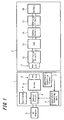
- FIG. 1 is a block diagram that illustrates a cradle 1 in accordance with an embodiment of the present invention and a mobile phone unit 2.
- the mobile 2 can be mounted on the cradle 1 to charge a secondary cell (also simply referred to as a battery) installed in the mobile phone unit 2.
- a secondary cell also simply referred to as a battery
- the cradle 1 of the present embodiment includes an AC (alternating current) adaptor 3, an oscillator 4, a primary transmission coil 5, a driver 6, a temperature-detecting element 7, and a temperature-detecting unit 8.
- the AC adaptor 3 is provided for converting consumer power supply into direct-current (DC) power supply.
- the oscillator 4 is provided for oscillation at a predetermined frequency.
- the primary transmission coil 5 is provided as a noncontact power-transmission coil on the power transmission side.
- the drive 6 is provided for supplying an AC power to the primary transmission coil 5.
- the temperature-detecting element 7 is mounted on the optimal position (described later) of the primary transmission coil 5 so as to be in contact with the primary transmission coil 5.
- the temperature-detecting unit 8 is provided for detecting the temperature of the primary transmission coil 5 on the basis of an output of the temperature detection from the temperature-detecting element 7.
- the cradle 1 further includes a control circuit 9 for terminating the charging under control as follows.
- the control circuit 9 coverts a DC power from the AC adaptor 3 into an AC power on the basis of an oscillation frequency signal from the oscillator 4 and supplies the AC power to the primary transmission coil 5 through the driver 6.
- the control circuit terminates the supply of power to the primary transmission coil 5.
- the mobile phone unit 2 includes a secondary-transmission coil 11, a rectifying circuit 12, a LDO (low dropout) regulator 13, a charging circuit 15, and a control circuit 14.
- the secondary-transmission coil 11 is provided as a noncontact power-transmission coil on the power-receiving side.
- the rectifying circuit 12 is provided for converting an AC power received from the primary transmission coil 5 to a DC power.
- the LDO regulator 13 is provided for converting a DC power from the rectifying circuit 12 to a DC power at a predetermined voltage.
- the charging circuit 15 is provided for carrying out the charging by supplying the DC power at a predetermined voltage to a battery (secondary cell) 16.
- the control circuit 14 is provided for supplying the DC power at the predetermined circuit 15 to the charging circuit 15.
- FIGS. 2 to 4 illustrate the configuration of the primary transmission coil 5, which is the noncontact power-transmission coil on the power transmission side. These figures also illustrate the configuration of the secondary-transmission circuit 11, which is the noncontact power-transmission coil on the power receiving side.
- each of the primary transmission coil 5 and the secondary-transmission circuit 11 may be equivalently represented as a "noncontact power-transmission coil 21WS". Therefore, FIG. 2 is a front view of the noncontact power-transmission coil 21WS formed by sticking a planar coil to a flexible printed-circuit board 30.
- FIG. 3 is a front view of the flexible printed-circuit board 30 without the attachment of the planar coil.
- FIG. 4 is a schematic cross sectional view of the noncontact power-transmission coil 21WS.
- the noncontact power-transmission coil 21WS includes a planar coil.
- the planar coil is formed of a single or twisted wire 40 having a surface provided with an insulating layer.
- the wire is spirally wound in a substantially same plane.
- One flat surface of the planar coil is stuck on the surface of the flexible printed-circuit board 30 through an adhesion sheet 42.
- a magnetic sheet 43 is stuck on the other flat surface of the planar coil so that the magnetic sheet 43 can entirely cover the other flat surface of the planar coil through an adhesion sheet 41.
- the magnetic sheet 43 is provided for efficiently forming a magnetic path of the planar coil to cause an increase in inter-linkage magnetic flux between the primary transmission coil 5 and the secondary-transmission circuit 11, while preventing undesired radiation with the magnetic field generated from each of the coils.
- a metal sheet (not shown), such as one made of aluminum, may be stuck on the outer surface of the magnetic sheet if required.
- the flexible printed-circuit board 30 is a substrate in the shape of a thin layer, for example, one using a polyimide resin as a base material.
- a surface-insulating layer is formed on the flexible printed-circuit board 30, except of a first coil contact portion 36, a second coil contact portion 35, a first external connection terminal 31, and a second external connection terminal 32.
- the first coil contact portion 36 is formed on the flexible printed-circuit board 30 so that it can be arranged in an inner peripheral portion 37 of the planar coil when the planar coil is stuck on the flexible printed-circuit board 30.
- the second coil contact portion 35 is arranged in the vicinity of the outside of a planar coil external peripheral portion 38.
- first coil contact portion 36 and the first external connection terminal portion 31 are electrically connected to each other through a first internal conductor pattern 33 formed under the surface-insulating layer.
- second coil contact portion 35 and the second external terminal portion 32 are electrically connected to each other through a second internal conductor pattern 34 formed under the surface insulating layer.
- the first coil contact portion 36 is electrically connected to one end of the electric wire in the inner peripheral portion 37 of the planar coil at the start of the winding.
- the second coil contact portion 35 is electrically connected to the other end of the electric wire in the outer peripheral portion 38 of the planar coil at the end of the winding.
- noncontact power-transmission coil 21WS is formed as described above, overlapped portions of the electric wire can be avoided. Thus, the thickness of the noncontact power-transmission coil 21WS can be extremely reduced.
- the noncontact power-transmission coil which is provided as each of the above primary transmission coil 5 and the above secondary-transmission circuit 11, may be a multi-layered noncontact power-transmission coil 21PS formed by stacking a plurality of flexible-printed circuit boards provided with planar coil patterns.
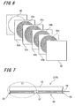
- FIG. 5 is a front view of the noncontact power-transmission coil 21PS having a multi-layered flexible printed-circuit board.
- FIG. 6 is a schematic perspective view of the noncontact power-transmission coil 21PS in which the respective layers are illustrated in separation from one another.
- FIG. 7 is a schematic cross sectional view of the noncontact power-transmission coil 21PS having a multi-layered flexible printed-circuit board.
- FIG. 8 is an enlarged view of the portion enclosed with an ellipse E1 shown in FIG. 7 .
- the noncontact power-transmission coil 21PS includes, for example, a four-layered structure.
- Each of a first-layer substrate 64a, a second-layer substrate 64b, a third-layer substrate 64c, and a fourth-layer substrate 64d may be made of polyimide resin or the like and formed with spirally-wound linear conductor patterns 60 formed on the respective sheet-shaped substrates.
- a surface insulating layer 62 is formed on the surface of the top layer, the first layer substrate 64a, and an adhesion layer and an interlayer insulating layer 63a are formed between the first layer substrate 64a and the second layer substrate 64b.
- an adhesion layer and an interlayer insulating layer 63b are formed between the second layer substrate 64b and the third layer substrate 64c.
- an adhesion layer and an interlayer insulating layer 63c are formed between the third layer substrate 64c and the fourth layer substrate 64d.
- a magnetic sheet 43 is stuck on the back side of the bottom layer, the fourth layer substrate 64d, through the adhesion layer and the insulating layer 63d.
- the ends of the respective conductive patterns 60 of the first to fourth layer substrates 64a to 64d, which are located at an inner peripheral portion 57, are electrically connected to one another through first through-holes 56.
- the ends of the respective conductive patterns 60 of the first to fourth layer substrates 64a to 64d, which are located at an outer peripheral portion 58, are electrically connected to one another through second through-holes 55.
- first through-holes 56 for the conductor patterns 60 of the respective layers which are located at the inner peripheral portion 57, are electrically connected to the through-holes 61 for the conductor patterns of the respective layers, which are located at the outer peripheral portion 58.
- a metal sheet such as one made of aluminum, may be stuck on the outer side of the magnetic sheet 43 if required.
- the second through-hole 55 of the fourth layer substrate 64d is electrically connected to a second external connection terminal portion 52 through a second inner conductor pattern 54.
- the first through-hole 56 of the fourth layer substrate 64d is electrically connected to a first external connection terminal portion 51 through the above through-hole 61 and a first inner conductor pattern 53.
- the planar coil is formed with the conductor pattern 60 of the flexible printed-circuit board.
- such a noncontact power-transmission coil 21PS can be thinner than the noncontact power-transmission coil 21WS having the planar coil made of the electric wire as described above.
- the cradle 1 in accordance with the present embodiment uses either the above noncontact power transmission coil 21WS or the noncontact power transmission coil 21PS and an electromagnetic induction is then applied to carry out a power transmission from the cradle 1 to the mobile phone unit 2.
- an eddy current may be caused in a foreign metal substance, such as a coin, when the foreign metal substance is placed on the above cradle 1.
- the foreign metal substance may be abnormally heated.
- either the noncontact power-transmission coil 21WS or the noncontact power-transmission coil 21PS, which is the primary transmission coil 5 on the cradle 1, is provided with a temperature-detecting element 7.
- the control circuit 9 of the cradle 1 is designed to terminate the charging under control when the temperature detected by the temperature-detecting element 7 exceeds a predetermined temperature.
- the noncontact power-transmission coil 21WS having the planar coil made of the above wound electric wire 40 is used as the primary transmission coil 5.
- the temperature-detecting element 7 is directly formed as a temperature-detecting element layer in the conductor pattern of the flexible printed-circuit board 30.
- both a third external connection terminal portion 81 and a fourth external connection terminal portion 82 are formed on the flexible printed-circuit board 30.
- These portions 81, 82 are responsible for receiving temperature-detecting signals output to the outside from the above temperature-detecting element 7.
- wiring patters are formed between the third and fourth external connection terminal portions 81, 82 and the temperature-detecting element 7, respectively.
- the primary transmission coil 5 used may be the noncontact power-transmission coil 21PS of the multi-layered flexible printed-circuit board having the planer coil made of the conductor pattern 60 as described above.
- the temperature-detecting element 7 may be directly formed as a temperature-detecting element layer in the conductor pattern of, for example, the first layer substrate 64a of the multi-layered flexible printed-circuit board as shown in FIG. 8 .
- wiring patterns (not shown) for the transmission of temperature-detecting signals from the temperature-detecting element 7 (temperature-detecting element layer) are connected to the third external connection terminal portion 81 and the fourth external connection terminal portion 82 through a through-hole and so on as is the above case shown in FIG. 3 .
- the direct formation of the temperature-detecting element 7 as a temperature-detecting element layer in the conductor pattern of the flexible printed-circuit board can prevent the noncontact power-transmission coil from causing a disadvantage of increased thickness.
- the cradle 1 is provided with only one temperature-detecting element 7 as described above.
- the cradle 1 may be provided with a plurality of temperature-detecting elements 7. Even if two or more temperature-detecting elements 7 are mounted, there is no increase in the thickness of the noncontact power-transmission coil because the temperature-detecting elements 7 are directly formed in the conductor patterns of the respective flexible printed-circuit boards. [Setting position of temperature-detecting element]
- the temperature-detecting element 7 is directly formed as a temperature-detecting element layer in the conductor pattern of the flexible printed-circuit board.
- an increase in temperature of a foreign metal substance, such as a coin due to the placement of the foreign metal substance on the cradle 1, largely relates to the size of the foreign metal substance and the position at which the foreign metal substance is mounted.
- a foreign metal substance has a predetermined size or less or the foreign metal substance is placed at a predetermined distance or more from the primary transmission coil 5.
- the increase in the temperature of the foreign material is small and the above problem of an abnormal increase in temperature may not occur.
- the setting position of the temperature-detecting element 7 for detecting the temperature of the primary transmission coil 5 is important. Therefore, the applicants of the present invention mount the temperature-detecting element 7 on the optimal position determined by studying: a material of the foreign metal substance, the size thereof, the location thereof mounted on the cradle 1, and the increase in temperature with respect to the respective positions on the cradle 1.
- the applicants have measured an increase in temperature of a foreign metal substance after placing the foreign metal substance on a predetermined position on the primary transmission coil 5.
- a position corresponds to the central portion (are where a hollow is present and magnetic flux is concentrated) of the primary transmission coil 5.
- the foreign metal substance may be any of materials, such as a 100-yen coin, a 10-yen coin, a 1-yen coin, the edge of a utility knife, a clip, a solder alloy, a white metal material, a phosphor bronze material, and a stainless material.
- materials such as a white metal material, a phosphor bronze material, and a stainless material showed measurement results in which the temperatures of the materials may increase to an abnormal temperature within a short time. This is because these materials tend to allow the passage of a current when applied with magnetic force and show large resistances.
- the applicants have placed foreign metal substances made of different materials on the respective measurement points and then measured the increase in temperature of each foreign metal substance.
- the foreign metal substances used are "100-yen coins” and "phosphor bronze materials”.
- Each of these foreign metal substances is placed on a first to fifth measurement points on the primary transmission coil 5 and the increase in temperature was then measured.
- FIG. 10 is a graphical representation of the increase in temperature at each measurement point when a "100-yen coin" is used as a foreign metal substance. As shown in FIG. 10 , when a "100-yen coin” is used as the foreign metal substance, the measurement results show that the more the setting position of the "100-yen coin” comes close to the central portion of the primary transmission coil 5, the more the increase in the temperature is large.
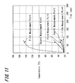
- FIG. 11 is a graphical representation of the increase in temperature at each measurement point when a "phosphor bronze material" (10 mm in side length, 1 mm in thickness, and 10 mm 2 in area of a regular tetragon) is used as the foreign metal substance.
- a "phosphor bronze material” 10 mm in side length, 1 mm in thickness, and 10 mm 2 in area of a regular tetragon
- the results of the measurement show the follows.
- the increase in the temperature is large in the case of the "phosphor bronze material” being mounted on the central portion of the primary transmission coil 5. If the setting position of the "phosphor bronze material" is apart from the central portion of the primary transmission coil 5 even if only slightly, the increase in temperature may is not so large.
- FIG. 12A is a table representing the relationship between the areas of the respective foreign metal substances made of "phosphor bronze" and the different durations of current application to the primary transmission coil 5.
- a phosphor bronze material (3 mm in side length, 1 mm in thickness, and 9 mm 2 in area of a regular tetragon) was mounted on the central portion on the primary transmission coil 5.
- the primary transmission coil 5 was then sequentially applied with current for 30 seconds, 60 seconds, 90 seconds, 120 seconds, and 180 seconds in this order. Consequently, as shown in FIG.
- the results of the measurement indicated that the temperature of the phosphor bronze material increased from 30°C (initial temperature) to a series of 36. 4°C (current application for 30 sec.), 39°C (current application for 60 sec.), 40.5°C (current application for 90 sec.), 42.2°C (current application for 120 sec.), and 43.9°C (current application for 180 sec.) in this order.
- a phosphor bronze material (12 mm in side length, 1 mm in thickness, and 141 mm 2 in area of a regular tetragon) was mounted on the central portion on the primary transmission coil 5. The primary transmission coil 5 was then sequentially applied with current for 30 seconds, 60 seconds, 90 seconds, 120 seconds, and 180 seconds in this order.
- FIG. 12B is a graphical representation of the increase in the temperature when the above "phosphor bronze material” with an area of "3 mm 2 " “5 mm 2 " “6 mm 2 " “7 mm 2 “ “8 mm 2 “, “10 mm 2 “, or “12 mm 2 " was placed on the central portion of the primary transmission coil 5.
- FIG. 12C is a graphical representation of the relationship between the area of the above “phosphor bronze material” and the increase in the temperature. As shown in the graph, the more the area of the "phosphor bronze material” mounted on the primary transmission coil 5 increases, the larger the increase of the temperature becomes.
- the results of the measurement shows that the foreign metal substance reaches the above "dangerous temperature” when the area of the foreign metal substance is "7 mm 2 " or more.
- the results of the measurement show that the possibility of allowing the foreign metal substance to reach the above dangerous temperature is extremely low when the area of the foreign metal substance is smaller than "7 mm 2 ".
- FIG. 13A is a table that represents the saturated temperatures of the above respective phosphor bronze materials and the temperatures detected by the temperature-detecting element 7.
- One of the "phosphor bronze material" used is in the form of a regular tetragon with a side length of 10 mm, a thickness of 1 mm, and an area of 100 mm 2 and the other thereof is one with a side length of 25 mm, a thickness of 1 mm, and an area of 625 mm 2 .
- the phosphor bronze material with an area of 100 mm 2 is placed on each of the positions at a distance of 2 mm, 4 mm, 6 mm, 8 mm, and 10 mm from the central portion of the primary transmission coil 5 in this order.
- the saturated temperature of the phosphor bronze material and the temperature actually detected by the temperature-detecting portion 7 are measured at every position.
- the saturated temperatures of the phosphor bronze material at the respective positions as described above are 148°C, 112°C, 58°C, 52°C, and 48°C in this order.
- the temperatures detected by the temperature-detecting element 7 at the respective positions are 121°C, 98°C, 48°C, and 42°C in this order.
- the phosphor bronze material of 625 mm 2 in area is placed on each of the positions at a distance of 2 mm, 4 mm, 6 mm, 8 mm, and 10 mm from the central portion of the primary transmission coil 5 in this order. Subsequently, the saturated temperature of the phosphor bronze material and the temperature actually detected by the temperature-detecting portion 7 are measured at every position. As a result, the saturated temperatures of the phosphor bronze material at the respective positions as described above are 153°C, 139°C, 117°C, 76°C, and 53°C in this order.
- temperatures detected by the temperature-detecting element 7 at the respective positions are 125°C, 118°C, 104°C, 51°C, and 41°C in this order.
- the applicants have fixed the setting position of the foreign metal substance on the central portion of the primary transmission coil 5. Subsequently, the setting position of the temperature-detecting element 7 is gradually moving away from the central portion of the primary transmission coil 5. Simultaneously, the temperature-detecting element 7 detects the saturated temperatures of the respective foreign metal substances and the temperatures of the respective setting positions.
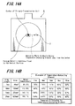
- FIG. 14B is a table that represents the saturated temperatures of the above respective phosphor bronze materials and the temperatures detected by the temperature-detecting element 7.
- a "phosphor bronze material" in the form of a regular tetragon with a side length of 7 mm, a thickness of 1 mm in thickness, and an area of 49 mm 2 was mounted on the central portion on the primary transmission coil 5.
- the setting position of the temperature-detecting element 7 is shifted to the respective positions at distances of 2 mm, 4 mm, 6 mm, 8 mm, and 10 mm in this order from the central portion of the primary transmission coil 5.
- the saturated temperature of the phosphor bronze material and the temperature actually detected by the temperature-detecting element 7 at each position are measured, the saturated temperature of the above phosphor bronze material is 85.2°C and the temperatures detected by the temperature-detecting element 7 at the respective positions are 76°C, 73°C, 71°C, 60°C, and 50°C in this order.
- a "phosphor bronze material" in the form of a regular tetragon with a side length of 10 mm, a thickness of 1 mm in thickness, and an area of 100 mm 2 was mounted on the central portion on the primary transmission coil 5.
- the setting position of the temperature-detecting element 7 is shifted to the respective positions at distances of 2 mm, 4 mm, 6 mm, 8 mm, and 10 mm in this order from the central portion of the primary transmission coil 5.
- the saturated temperature of the phosphor bronze material and the temperature actually detected by the temperature-detecting element 7 at each position are measured, the saturated temperature of the above phosphor bronze material is 112.4°C and the temperatures detected by the temperature-detecting element 7 at the respective positions are 98°C, 93°C, 93°C, 62°C, and 50°C in this order.
- a "phosphor bronze material" in the form of a regular tetragon with a side length of 15 mm, a thickness of 1 mm in thickness, and an area of 225 mm 2 was mounted on the central portion on the primary transmission coil 5.
- the setting position of the temperature-detecting element 7 is shifted to the respective positions at distances of 2 mm, 4 mm, 6 mm, 8 mm, and 10 mm in this order from the central portion of the primary transmission coil 5.
- the saturated temperature of the phosphor bronze material and the temperature actually detected by the temperature-detecting element 7 at each position are measured, the saturated temperature of the above phosphor bronze material is 143.1°C and the temperatures detected by the temperature-detecting element 7 at the respective positions are 131°C, 129°C, 116°C, 98°C, and 61°C in this order.
- a "phosphor bronze material" in the form of a regular tetragon with a side length of 25 mm, a thickness of 1 mm in thickness, and an area of 625 mm 2 was mounted on the central portion on the primary transmission coil 5.
- the setting position of the temperature-detecting element 7 is shifted to the respective positions at distances of 2 mm, 4 mm, 6 mm, 8 mm, and 10 mm in this order from the central portion of the primary transmission coil 5.
- the saturated temperature of the phosphor bronze material and the temperature actually detected by the temperature-detecting element 7 at each position are measured, the saturated temperature of the above phosphor bronze material is 153.1°C and the temperatures detected by the temperature-detecting element 7 at the respective positions are 129°C, 134°C, 128°C, 98°C, and 89°C in this order.
- the central portion of the primary transmission coil 5 is a portion where magnetic force lines are concentrated. Therefore, when the central portion of the primary transmission coil 5 is provided with the temperature-detecting element 7, the temperature-detecting element 7 itself will be heated. As a result, it may become difficult to detect the temperature of the foreign metal substance correctly. For this reason, it is preferable to place the temperature-detecting element 7 at a position distant from the central portion of the primary transmission coil 5. From the results of the measurement, it is found that the temperature-detecting element 7 may be preferably located at a position distant from the central portion of the primary transmission coil 5. In other words, the temperature-detecting element 7 may be mounted at a distance of 4 mm to 6 mm from the central portion of the primary transmission coil 5.
- the temperature-detecting element 7 formed in the primary transmission coil 5 may not directly detect the temperature of the foreign metal substance.
- the temperature-detecting element 7 detects the amount of heat transmitted to the primary transmission coil 5 from a heat-generating foreign metal substance. In other words, the temperature-detecting element 7 detects the temperature of the foreign metal substance indirectly through the primary transmission coil 5. Therefore, as shown in FIG. 14B , the temperature detected by the temperature-detecting element 7 is lower than the actual temperature of the foreign metal substance.
- the present applicants have measured the difference between the actual temperature of a foreign metal substance and the temperature thereof detected by the temperature-detecting element 7.
- the temperature-detecting element 7 is placed on each of first to third measurement points at a distance of 5 mm from the central portion of the primary transmission coil 5.
- the foreign metal substance is placed on the central portion of the primary transmission coil 5. The temperature of the foreign metal substance and the temperature detected by the temperature-detecting element 7 are then measured.
- FIG. 15B is a graphical representation of the temperature of a stainless steel plate of 25 mm in side length and the temperature detected by the temperature-detecting element 7.
- the stainless steel plate is placed on the central portion of the primary transmission coil 5.
- the temperature-detecting element 7 detects a temperature of about 60°C.
- the temperature-detecting element 7 detects a temperature of about 73°C at each measurement point as described above. In this case, the difference observed is about 11°C to 12°C.
- the temperature-detecting element 7 may be arranged as follows.
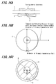
- the temperature-detecting element 7 is mounted on the side of a contact surface between the cradle 1 and the primary transmission coil 5 as shown in FIG. 16A .
- the temperature-detecting element 7 is located within the range of not more than the diameter of the primary transmission coil 5 from the center position of the primary transmission coil 5 as shown in FIG. 16B .
- the temperature-detecting element 7 is preferably on the side of a contact surface of cradle 1 between the mounting portion and the primary transmission coil 5.
- the center of the temperature-detecting element is preferably arranged between a position at a distance corresponding to the inner radius "r" of the primary transmission coil 5 from the center of the primary transmission coil 5 and a position at a distance corresponding to the inner diameter of the primary transmission coil 5.
- the applicants mount the temperature-detecting element 7 on the side of a contact surface between the cradle 1 and the primary transmission coil 5 such that the center of the temperature-detecting element 7 can be located at a position at a distance of 5 mm from the center of the primary transmission coil 5 in the cradle 1 according to the present embodiment.
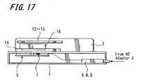
- FIG. 17 is a cross sectional view of a cradle 1 on which the mobile phone unit 2 is being mounted at the time of charging.
- the primary transmission coil 5 formed in the cradle 1 and the secondary-transmission circuit 11 in the mobile phone unit 2 come close to face each other.
- the control circuit 9 monitors a change in the state of the magnetic field of the primary transmission coil 5 by intermittent drive or the like.
- the control circuit 14 of the mobile phone unit 2 determines that the mobile phone unit 2 is mounted on the cradle 1 when a predetermined voltage level is detected. In other words, a voltage level in response to a change in the state of the magnetic field of the secondary power-transmission coil 11 reaches a predetermined voltage level when the mobile phone unit terminal is mounted on the cradle 1.
- the control circuit 9 of the cradle 1 and the control circuit 14 of the mobile phone unit 2 exchange their identification information each other through the primary and secondary transmission coils 5, 11 to authenticate each other. Subsequently, the cradle 1 carries out the supply of power to the battery 16 of the mobile phone unit 2 when such an exchange of identification information attains the mutual authentication. Thus, the charging of the battery 2 is initiated.
- the control circuit 9 of the cradle 1 coverts a DC power from the AC adaptor 3 into an AC power at a predetermined frequency on the basis of an oscillating frequency signal from the oscillator 2. Subsequently, the AC power is supplied to the primary transmission coil 5 through the driver 6.
- the AC power from the primary transmission coil 5 of the cradle 1 induces an AC power in the secondary-transmission coil 11.
- the induced AC power is rectified by the rectifying circuit 12 and then converted into a DC power at a predetermined voltage at the LDO 13.
- the control circuit 14 supplies the DC power from the LDO 13 to the battery 16 through the charging circuit 15. Consequently, the battery 16 can be charged.
- the power transmission to the mobile phone unit 2 may be carried out by electromagnetic induction with both the primary transmission coil 5 and the secondary-transmission circuit 11, which are noncontact power-transmission coils.
- an eddy current may be generated in a foreign metal substance, such as a coin, when the foreign metal substance is placed on the cradle 1.
- a foreign metal substance such as a coin
- the temperature-detecting element 7 formed on the cradle 1 indirectly detects the temperature of the mounted material (such as the mobile phone unit 2 or a foreign metal substance) through the primary transmission coil 5 and then transfers the detected output to the temperature-detecting unit 8.
- the mobile phone unit 2 mounted on the cradle 1 is generally heated to about 40°C while being charged.
- the mobile phone unit 2 placed on the cradle 1 causes an abnormal heat generation from any cause or when a foreign metal substance is placed on the cradle 1, the mobile phone unit 2 and the foreign metal substance can be heated to the above dangerous temperature, 75°C or more.
- the temperature-detecting element 7 indirectly detects the temperature of the material mounted on the cradle 1 through the primary transmission coil 5.
- both the temperature-detecting element 7 and temperature-detecting unit 8 detect a temperature of 60°C.
- the control circuit 9 recognizes an increase in temperature of the material mounted on the cradle 1 to the dangerous temperature.
- the control circuit 9 terminates the supply of power to the primary transmission coil 5.
- the charging can be interrupted as a termination under control. Consequently, the material mounted on the cradle 1 can be prevented from an abnormal increase in temperature, thereby allowing the cradle 1 to attain the enhanced safety.
- the temperature-detecting element 7 is mounted at the optimum position to detect the temperature of the material mounted on the cradle 1, which is determined on the basis of each measurement as described above. Therefore, the temperature of the material mounted on the cradle 1 is detected in real time and then the above charging can be terminated under control with accuracy.
- the supply of power to the primary transmission coil 5 is terminated under control upon detecting an increase in temperature of the material mounted on the cradle 1 to the dangerous temperature.
- the supply of power may be terminated under control in response to the temperature gradient of the above mounted material detected by the temperature-detecting element 7.
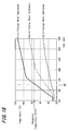
- FIG. 18 is a graphical representation of the temperatures of the first to third foreign metal substances mounted on the cradle 1, which vary with the durations of power supply to the primary transmission coil 5.
- the third foreign metal substance does not reach the dangerous temperature even if the duration of power supply to the primary transmission coil 5 is extended.
- the first foreign metal substance reaches the dangerous temperature when the duration of power supply to the primary transmission coil 5 is about 100 seconds.
- the second foreign metal substance reaches the dangerous temperature when the duration of power supply to the primary transmission coil 5 is about 230 seconds.
- a graph with a high temperature gradient is obtained in the case of the foreign metal substance reaching the dangerous temperature.
- the control circuit 9 detects the temperatures detected by the above temperature-detecting element 7 and the above temperature-detecting unit 8 at the time of 60 seconds passed from the initiation of power supply to the primary transmission coil 5. In addition, the control circuit 9 detects the temperatures detected by the above temperature-detecting element 7 and the above temperature-detecting unit 8 at the time of 90 seconds passed from the initiation of power supply to the primary transmission coil 5. Furthermore, on the basis of the detected temperatures at the respective time points, the gradient of temperature increase of a device presently mounted on the cradle 1 is detected. When the gradient is greater than a predetermined level, the power supply to the primary transmission coil 5 is terminated under control.
- the power supply to the primary transmission coil 5 can be terminated prior to the increase in temperature of the material mounted on the cradle 1 up to the dangerous temperature. Therefore, the safety of the cradle 1 can be improved.
- the termination control may be carried out when an increased level of the above detected temperature reaches a predetermined level or more within a predetermined period of time, or on the basis of the absolute value of the detected temperature.
- the supply of power to the primary transmission coil 5 can be terminated before an increase of temperature of the material mounted on the cradle 1 to the dangerous temperature. Therefore, the safety of the cradle 1 can be improved.
- the cradle 1 may be further provided with a peripheral temperature-detecting element for detecting the temperature of the periphery of a portion corresponding to the primary transmission coil 5.
- the above termination control may be carried out when the following difference reaches a predetermined level. That is, the difference is between the temperatures detected by the above temperature-detecting element and unit 7, 8 (the temperature of the portion corresponding to the primary transmission coil 5) and the peripheral temperature detected by the above peripheral temperature-detecting element.
- the supply of power to the primary transmission coil 5 can be terminated before the temperature of the mounted material of the cradle 1 reaches the dangerous temperature. Therefore, the stability of the cradle 1 can be improved.
- the cradle 1 of the present embodiment detects the temperature of a mounted material on the cradle 1 by a temperature-detecting element 7 located at the optimal position obtained from various measurement results.
- the supply of power to the primary transmission coil 5 is terminated under control upon detecting an abnormal increase in temperature of the above mounted material. Therefore, an abnormal increase in temperature of the mounted material of the cradle 1 can be quickly controlled. As a result, the safety of the cradle 1 provided as a noncontact charging device can be improved.
- the embodiment of the present invention is applied to the cradle 1 for charging the mobile phone unit 2.
- any embodiment of the present invention may be applied to any charging device suitable for charging portable devices, such as personal handy-phone systems (PHSs), personal digital assistants (PDAs), portable game devices, and book-type personal computers.
- PHSs personal handy-phone systems
- PDAs personal digital assistants
- portable game devices portable game devices
- book-type personal computers book-type personal computers
Landscapes
- Engineering & Computer Science (AREA)
- Power Engineering (AREA)
- Computer Networks & Wireless Communication (AREA)
- Charge And Discharge Circuits For Batteries Or The Like (AREA)
- Coils Or Transformers For Communication (AREA)
- Secondary Cells (AREA)
Applications Claiming Priority (1)
| Application Number | Priority Date | Filing Date | Title |
|---|---|---|---|
| JP2007001644A JP5049018B2 (ja) | 2007-01-09 | 2007-01-09 | 非接触充電装置 |
Publications (3)
| Publication Number | Publication Date |
|---|---|
| EP1944851A2 true EP1944851A2 (de) | 2008-07-16 |
| EP1944851A3 EP1944851A3 (de) | 2014-01-15 |
| EP1944851B1 EP1944851B1 (de) | 2023-01-04 |
Family
ID=39278314
Family Applications (1)
| Application Number | Title | Priority Date | Filing Date |
|---|---|---|---|
| EP08250071.1A Active EP1944851B1 (de) | 2007-01-09 | 2008-01-08 | Ein berührungsloses Ladegerät |
Country Status (4)
| Country | Link |
|---|---|
| US (1) | US8089245B2 (de) |
| EP (1) | EP1944851B1 (de) |
| JP (1) | JP5049018B2 (de) |
| CN (1) | CN101304178B (de) |
Cited By (15)
| Publication number | Priority date | Publication date | Assignee | Title |
|---|---|---|---|---|
| EP2226819A1 (de) * | 2007-12-25 | 2010-09-08 | Panasonic Electric Works Co., Ltd | Flachspule und kontaktfreie übertragungsvorrichtung damit |
| DE102010026780A1 (de) * | 2010-07-09 | 2012-01-12 | Audi Ag | Messen einer Temperatur bei einer kontaktlosen Übertragung von Energie |
| EP2458710A1 (de) * | 2009-07-23 | 2012-05-30 | Fujitsu Limited | Stromübertragungsvorrichtung, drahtloses stromversorgungssystem und drahtlose stromversorungsvorrichtung |
| EP2555379A1 (de) * | 2010-03-31 | 2013-02-06 | Honda Motor Co., Ltd. | Kontaktloses aufladesystem |
| WO2014112019A1 (en) * | 2013-01-16 | 2014-07-24 | Sony Corporation | Power receiver, non-contact power transmission system, and method of controlling received-power voltage |
| CN105393430A (zh) * | 2013-07-11 | 2016-03-09 | 松下知识产权经营株式会社 | 非接触式供电装置及非接触式受电装置 |
| US9607757B2 (en) | 2011-11-02 | 2017-03-28 | Panasonic Corporation | Non-contact wireless communication coil, transmission coil, and portable wireless terminal |
| US9667086B2 (en) | 2012-06-28 | 2017-05-30 | Panasonic Intellectual Property Management Co., Ltd. | Mobile terminal |
| US9701212B2 (en) | 2010-01-05 | 2017-07-11 | Access Business Group International Llc | Inductive charging system for electric vehicle |
| US9735606B2 (en) | 2012-06-28 | 2017-08-15 | Panasonic Intellectual Property Management Co., Ltd. | Mobile terminal including charging coil and wireless communication coil, wireless charging module including charging coil and wireless communication coil |
| US9935481B2 (en) | 2012-02-17 | 2018-04-03 | Panasonic Intellectual Property Management Co., Ltd. | Mobile terminal including wireless charging module and battery pack |
| EP3255757A3 (de) * | 2016-06-09 | 2018-04-18 | Scott Technologies, Inc. | Drahtloses resonanzenergietransfersytem für persönliche schutzausrüstung |
| US9954396B2 (en) | 2011-06-14 | 2018-04-24 | Panasonic Corporation | Electronic device including non-contact charging module |
| US10204734B2 (en) | 2011-11-02 | 2019-02-12 | Panasonic Corporation | Electronic device including non-contact charging module and near field communication antenna |
| US10218222B2 (en) | 2011-01-26 | 2019-02-26 | Panasonic Intellectual Property Management Co., Ltd. | Non-contact charging module having a wireless charging coil and a magnetic sheet |
Families Citing this family (81)
| Publication number | Priority date | Publication date | Assignee | Title |
|---|---|---|---|---|
| US7952322B2 (en) | 2006-01-31 | 2011-05-31 | Mojo Mobility, Inc. | Inductive power source and charging system |
| US8169185B2 (en) | 2006-01-31 | 2012-05-01 | Mojo Mobility, Inc. | System and method for inductive charging of portable devices |
| US11201500B2 (en) | 2006-01-31 | 2021-12-14 | Mojo Mobility, Inc. | Efficiencies and flexibilities in inductive (wireless) charging |
| US7948208B2 (en) | 2006-06-01 | 2011-05-24 | Mojo Mobility, Inc. | Power source, charging system, and inductive receiver for mobile devices |
| US11329511B2 (en) | 2006-06-01 | 2022-05-10 | Mojo Mobility Inc. | Power source, charging system, and inductive receiver for mobile devices |
| JPWO2009040998A1 (ja) * | 2007-09-27 | 2011-01-13 | パナソニック株式会社 | 非接触充電器 |
| KR100976161B1 (ko) * | 2008-02-20 | 2010-08-16 | 정춘길 | 무접점충전시스템 및 그의 충전제어방법 |
| JP5072690B2 (ja) * | 2008-04-04 | 2012-11-14 | シャープ株式会社 | 無接点式充電装置 |
| US20110050164A1 (en) | 2008-05-07 | 2011-03-03 | Afshin Partovi | System and methods for inductive charging, and improvements and uses thereof |
| JP5425539B2 (ja) * | 2009-01-27 | 2014-02-26 | パナソニック株式会社 | 非接触電力伝送システム |
| JP4849142B2 (ja) * | 2009-02-27 | 2012-01-11 | ソニー株式会社 | 電力供給装置および電力伝送システム |
| DE102009033237A1 (de) * | 2009-07-14 | 2011-01-20 | Conductix-Wampfler Ag | Vorrichtung zur induktiven Übertragung elektrischer Energie |
| US8226294B2 (en) * | 2009-08-31 | 2012-07-24 | Arizant Healthcare Inc. | Flexible deep tissue temperature measurement devices |
| US8321029B2 (en) * | 2009-09-18 | 2012-11-27 | Boston Scientific Neuromodulation Corporation | External charger usable with an implantable medical device having a programmable or time-varying temperature set point |
| KR20110034773A (ko) * | 2009-09-29 | 2011-04-06 | 삼성전자주식회사 | 유도성 결합 방식을 이용한 무선 충전기 |
| US8575944B2 (en) * | 2009-11-03 | 2013-11-05 | Robert Bosch Gmbh | Foreign object detection in inductive coupled devices |
| JP2011114985A (ja) * | 2009-11-27 | 2011-06-09 | Sanyo Electric Co Ltd | 電池内蔵機器と充電台 |
| DE102010012356B4 (de) | 2010-03-22 | 2021-04-29 | Sew-Eurodrive Gmbh & Co Kg | System zur berührungslosen Energieübertragung an ein Fahrzeug |
| US8292495B2 (en) | 2010-04-07 | 2012-10-23 | Arizant Healthcare Inc. | Zero-heat-flux, deep tissue temperature measurement devices with thermal sensor calibration |
| US8292502B2 (en) * | 2010-04-07 | 2012-10-23 | Arizant Healthcare Inc. | Constructions for zero-heat-flux, deep tissue temperature measurement devices |
| EP2580844A4 (de) | 2010-06-11 | 2016-05-25 | Mojo Mobility Inc | Interoperabilität unterstützendes system für drahtlose stromübertragung sowie mehrpolige magneten zur verwendung damit |
| US8917511B2 (en) * | 2010-06-30 | 2014-12-23 | Panasonic Corporation | Wireless power transfer system and power transmitting/receiving device with heat dissipation structure |
| IN2013CN00307A (de) * | 2010-07-02 | 2015-07-03 | Koninkl Philips Electronics Nv | |
| WO2012004092A2 (en) * | 2010-07-07 | 2012-01-12 | Robert Bosch Gmbh | Foreign object detection in inductive coupled wireless power transfer environment using thermal sensors |
| JP5593926B2 (ja) * | 2010-07-29 | 2014-09-24 | ソニー株式会社 | 給電システム、給電装置および電子機器 |
| JP5625723B2 (ja) * | 2010-10-15 | 2014-11-19 | ソニー株式会社 | 電子機器、給電方法および給電システム |
| JP5605153B2 (ja) | 2010-10-15 | 2014-10-15 | ソニー株式会社 | 給電装置、給電方法および給電システム |
| KR101414779B1 (ko) * | 2010-10-20 | 2014-07-03 | 한국전자통신연구원 | 무선 전력 전송 장치 |
| US9178369B2 (en) | 2011-01-18 | 2015-11-03 | Mojo Mobility, Inc. | Systems and methods for providing positioning freedom, and support of different voltages, protocols, and power levels in a wireless power system |
| US11342777B2 (en) | 2011-01-18 | 2022-05-24 | Mojo Mobility, Inc. | Powering and/or charging with more than one protocol |
| US10115520B2 (en) | 2011-01-18 | 2018-10-30 | Mojo Mobility, Inc. | Systems and method for wireless power transfer |
| US9356659B2 (en) | 2011-01-18 | 2016-05-31 | Mojo Mobility, Inc. | Chargers and methods for wireless power transfer |
| US9496732B2 (en) | 2011-01-18 | 2016-11-15 | Mojo Mobility, Inc. | Systems and methods for wireless power transfer |
| DE102011005682A1 (de) * | 2011-03-17 | 2012-09-20 | Robert Bosch Gmbh | Ladegerät, Akku und verfahren zur Erkennung eines Fremdobjekts |
| KR101397624B1 (ko) * | 2011-03-23 | 2014-05-22 | 주식회사 한림포스텍 | 무선 전력 전송 장치에서의 전력 전송 제어 방법 및 전력 전송 장치 |
| US8836287B2 (en) * | 2011-05-03 | 2014-09-16 | Apple Inc. | Time-domain multiplexing of power and data |
| US9354122B2 (en) | 2011-05-10 | 2016-05-31 | 3M Innovative Properties Company | Zero-heat-flux, deep tissue temperature measurement system |
| JP2013017247A (ja) * | 2011-06-30 | 2013-01-24 | Panasonic Corp | 非接触電力伝送に用いられる給電装置及び受電装置 |
| JP6064337B2 (ja) | 2011-08-10 | 2017-01-25 | ソニー株式会社 | 給電システム、給電装置および電子機器 |
| JP2014239560A (ja) * | 2011-09-29 | 2014-12-18 | 三洋電機株式会社 | 電池内蔵機器と充電台、及び電池内蔵機器 |
| CN107370249B (zh) * | 2012-03-14 | 2020-06-09 | 索尼公司 | 电力发送装置以及非接触电力提供系统 |
| US9722447B2 (en) | 2012-03-21 | 2017-08-01 | Mojo Mobility, Inc. | System and method for charging or powering devices, such as robots, electric vehicles, or other mobile devices or equipment |
| JP5749208B2 (ja) | 2012-03-26 | 2015-07-15 | 株式会社東芝 | 送電装置、受電装置、制御装置および無線電力伝送システム |
| DE102012211151B4 (de) * | 2012-06-28 | 2021-01-28 | Siemens Aktiengesellschaft | Ladeanordnung und Verfahren zum induktiven Laden eines elektrischen Energiespeichers |
| US9178361B2 (en) * | 2012-09-27 | 2015-11-03 | ConvenientPower, Ltd. | Methods and systems for detecting foreign objects in a wireless charging system |
| JP6087588B2 (ja) * | 2012-11-12 | 2017-03-01 | 三菱重工工作機械株式会社 | 変位センサの配線構造 |
| JP6126373B2 (ja) | 2012-12-13 | 2017-05-10 | パナソニック株式会社 | 無線モジュール及び無線通信装置 |
| WO2014125596A1 (ja) * | 2013-02-14 | 2014-08-21 | トヨタ自動車株式会社 | 受電装置および送電装置 |
| JP6282398B2 (ja) * | 2013-02-19 | 2018-02-21 | 矢崎総業株式会社 | 電磁誘導コイル |
| US9837846B2 (en) | 2013-04-12 | 2017-12-05 | Mojo Mobility, Inc. | System and method for powering or charging receivers or devices having small surface areas or volumes |
| CN105264347B (zh) * | 2013-05-14 | 2018-01-09 | 株式会社村田制作所 | 用于非接触电力传输的供电装置及受电装置 |
| CN105264742B (zh) * | 2013-05-14 | 2018-04-10 | 株式会社村田制作所 | 用于非接触电力传输的供电装置及受电装置 |
| RU2658324C2 (ru) * | 2013-07-17 | 2018-06-20 | Конинклейке Филипс Н.В. | Беспроводная индукционная передача энергии с управлением температурой приемника |
| US20160164333A1 (en) * | 2013-07-18 | 2016-06-09 | Panasonic Intellectual Property Management Co., Ltd. | Contactless charger, program therefor, and automobile equipped with same |
| CN203713733U (zh) * | 2013-11-19 | 2014-07-16 | 潘磊 | 一种用于安装车外摄像头的简易装置 |
| US9608470B2 (en) * | 2013-11-27 | 2017-03-28 | Nxp B.V. | Bank card presence detection to avoid a wireless charger demagnetizing a bank card |
| KR101762778B1 (ko) | 2014-03-04 | 2017-07-28 | 엘지이노텍 주식회사 | 무선 충전 및 통신 기판 그리고 무선 충전 및 통신 장치 |
| WO2015137430A1 (ja) * | 2014-03-14 | 2015-09-17 | 株式会社村田製作所 | ワイヤレス給電装置 |
| JP6196924B2 (ja) | 2014-03-21 | 2017-09-13 | Ihi運搬機械株式会社 | 非接触給電システム |
| DE102014207890A1 (de) * | 2014-04-28 | 2015-07-30 | Continental Automotive Gmbh | Fremdkörpererfassungsvorrichtung und Leistungs-Induktivladevorrichtung |
| US10295693B2 (en) * | 2014-05-15 | 2019-05-21 | Witricity Corporation | Systems, methods, and apparatus for foreign object detection loop based on inductive thermal sensing |
| EP3107176B1 (de) * | 2015-06-18 | 2018-04-04 | STMicroelectronics (Grand Ouest) SAS | Verfahren zur verwaltung eines kontaktlosen energietransfers von einem sender zu einem empfänger, und entsprechender sender |
| KR20170043393A (ko) * | 2015-10-13 | 2017-04-21 | 엘지이노텍 주식회사 | 코일 장치와 코일 장치의 제조 방법 및 코일 장치를 포함하는 무선전력전송장치 그리고 무선전력수신장치 |
| CN105356541B (zh) * | 2015-11-24 | 2019-06-11 | 深圳街电科技有限公司 | 一种移动电源的充电设备及其控制方法 |
| KR20170065236A (ko) * | 2015-12-03 | 2017-06-13 | 엘지이노텍 주식회사 | 무선 충전 장치, 그의 무선 전력 송신 방법, 및 이를 위한 기록 매체 |
| JP2017135838A (ja) * | 2016-01-27 | 2017-08-03 | パナソニックIpマネジメント株式会社 | 非接触給電システム |
| US10879704B2 (en) * | 2016-08-26 | 2020-12-29 | Nucurrent, Inc. | Wireless connector receiver module |
| CN107872098A (zh) * | 2016-09-23 | 2018-04-03 | 苹果公司 | 无线充电垫中的多层发射器线圈布置的互连 |
| US20180090973A1 (en) | 2016-09-23 | 2018-03-29 | Apple Inc. | Wireless charging mat with a transmitter coil arrangement including inner and outer coils having different structures |
| KR101833738B1 (ko) | 2017-07-07 | 2018-03-02 | 엘지이노텍 주식회사 | 무선전력전송 시스템 |
| KR102521724B1 (ko) * | 2017-09-29 | 2023-04-17 | 쓰리엠 이노베이티브 프로퍼티즈 캄파니 | 무선 전력 수신 장치와 이를 포함하는 무선 전력 시스템 및 포터블 디바이스 |
| KR102519193B1 (ko) * | 2017-09-29 | 2023-04-06 | 쓰리엠 이노베이티브 프로퍼티즈 캄파니 | 무선 전력 송신 장치와 이를 포함하는 무선 전력 시스템 |
| KR20190044280A (ko) * | 2017-10-20 | 2019-04-30 | 엘지이노텍 주식회사 | 코일장치 및 이를 구비한 무선충전장치 |
| CN109842218B (zh) * | 2017-11-29 | 2021-01-01 | 无锡华润矽科微电子有限公司 | 应用于无线充电系统的金属异物检测的装置及方法 |
| KR101905885B1 (ko) | 2018-02-20 | 2018-10-08 | 엘지이노텍 주식회사 | 무선전력 송신기 |
| US11444485B2 (en) | 2019-02-05 | 2022-09-13 | Mojo Mobility, Inc. | Inductive charging system with charging electronics physically separated from charging coil |
| JP7370164B2 (ja) | 2019-04-23 | 2023-10-27 | 富士電機メーター株式会社 | 電流センサ及び電力量計 |
| CN110077247A (zh) * | 2019-06-06 | 2019-08-02 | 北京有感科技有限责任公司 | 基于光纤传感网络的无线充电异物检测系统及检测方法 |
| CN116545135A (zh) * | 2019-08-01 | 2023-08-04 | 华为技术有限公司 | 无线充电系统的异物检测装置、方法及无线充电系统 |
| CN112713325A (zh) * | 2021-01-28 | 2021-04-27 | 格力博(江苏)股份有限公司 | 充电方法及充电设备 |
| KR20230056262A (ko) * | 2021-10-20 | 2023-04-27 | 삼성전자주식회사 | 무선 전력 송신 장치 |
Citations (1)
| Publication number | Priority date | Publication date | Assignee | Title |
|---|---|---|---|---|
| JP2003153457A (ja) | 2001-11-09 | 2003-05-23 | Denso Corp | 非接触式充電装置 |
Family Cites Families (15)
| Publication number | Priority date | Publication date | Assignee | Title |
|---|---|---|---|---|
| JP3153261B2 (ja) * | 1991-03-28 | 2001-04-03 | 日本電産株式会社 | 変圧器用ボビン |
| NL9101590A (nl) * | 1991-09-20 | 1993-04-16 | Ericsson Radio Systems Bv | Stelsel voor het laden van een oplaadbare accu van een draagbare eenheid in een rek. |
| US5466614A (en) * | 1993-09-20 | 1995-11-14 | At&T Global Information Solutions Company | Structure and method for remotely measuring process data |
| JPH07263935A (ja) * | 1994-03-24 | 1995-10-13 | Hochiki Corp | アンテナ装置 |
| US6222437B1 (en) * | 1998-05-11 | 2001-04-24 | Nidec America Corporation | Surface mounted magnetic components having sheet material windings and a power supply including such components |
| JP3818478B2 (ja) * | 1998-09-08 | 2006-09-06 | シャープ株式会社 | シート型トランス、その製造方法およびシート型トランスを含むスイッチング電源モジュール |
| KR100713319B1 (ko) * | 1999-05-07 | 2007-05-04 | 후루카와 덴키 고교 가부시키가이샤 | 배선 방법 및 배선 장치 |
| JP2001258182A (ja) * | 2000-03-08 | 2001-09-21 | Sharp Corp | 非接触による電力伝達装置 |
| JP3851504B2 (ja) * | 2000-11-16 | 2006-11-29 | 矢崎総業株式会社 | 自動車用スライドドア給電装置 |
| US6501364B1 (en) * | 2001-06-15 | 2002-12-31 | City University Of Hong Kong | Planar printed-circuit-board transformers with effective electromagnetic interference (EMI) shielding |
| JP2004208383A (ja) * | 2002-12-25 | 2004-07-22 | Aichi Electric Co Ltd | 非接触電源装置 |
| US20050212640A1 (en) * | 2004-03-24 | 2005-09-29 | Chiang Man-Ho | Multi-layer printed circuit board transformer winding |
| KR100765612B1 (ko) * | 2005-04-07 | 2007-10-09 | 엘에스전선 주식회사 | 무선 충전기 |
| JP2006339329A (ja) * | 2005-06-01 | 2006-12-14 | Seiko Epson Corp | 平面コイル装置及び基板並びに平面コイル固定方法 |
| US8342098B2 (en) * | 2005-07-12 | 2013-01-01 | Security Devices International Inc. | Non-lethal wireless stun projectile system for immobilizing a target by neuromuscular disruption |
-
2007
- 2007-01-09 JP JP2007001644A patent/JP5049018B2/ja active Active
-
2008
- 2008-01-07 US US12/007,073 patent/US8089245B2/en active Active
- 2008-01-08 EP EP08250071.1A patent/EP1944851B1/de active Active
- 2008-01-09 CN CN2008101277957A patent/CN101304178B/zh active Active
Patent Citations (1)
| Publication number | Priority date | Publication date | Assignee | Title |
|---|---|---|---|---|
| JP2003153457A (ja) | 2001-11-09 | 2003-05-23 | Denso Corp | 非接触式充電装置 |
Cited By (38)
| Publication number | Priority date | Publication date | Assignee | Title |
|---|---|---|---|---|
| EP2226819A1 (de) * | 2007-12-25 | 2010-09-08 | Panasonic Electric Works Co., Ltd | Flachspule und kontaktfreie übertragungsvorrichtung damit |
| EP2226819A4 (de) * | 2007-12-25 | 2013-05-29 | Panasonic Corp | Flachspule und kontaktfreie übertragungsvorrichtung damit |
| EP2458710A4 (de) * | 2009-07-23 | 2013-10-30 | Fujitsu Ltd | Stromübertragungsvorrichtung, drahtloses stromversorgungssystem und drahtlose stromversorungsvorrichtung |
| EP2458710A1 (de) * | 2009-07-23 | 2012-05-30 | Fujitsu Limited | Stromübertragungsvorrichtung, drahtloses stromversorgungssystem und drahtlose stromversorungsvorrichtung |
| US9701212B2 (en) | 2010-01-05 | 2017-07-11 | Access Business Group International Llc | Inductive charging system for electric vehicle |
| EP2555379A4 (de) * | 2010-03-31 | 2013-12-18 | Honda Motor Co Ltd | Kontaktloses aufladesystem |
| EP2555379A1 (de) * | 2010-03-31 | 2013-02-06 | Honda Motor Co., Ltd. | Kontaktloses aufladesystem |
| US9287720B2 (en) | 2010-03-31 | 2016-03-15 | Honda Motor Co., Ltd. | Non-contact charging system |
| US8992078B2 (en) | 2010-07-09 | 2015-03-31 | Audi Ag | Measuring a temperature during contactless transmission of energy |
| DE102010026780A1 (de) * | 2010-07-09 | 2012-01-12 | Audi Ag | Messen einer Temperatur bei einer kontaktlosen Übertragung von Energie |
| US10218222B2 (en) | 2011-01-26 | 2019-02-26 | Panasonic Intellectual Property Management Co., Ltd. | Non-contact charging module having a wireless charging coil and a magnetic sheet |
| US10468913B2 (en) | 2011-06-14 | 2019-11-05 | Sovereign Peak Ventures, Llc | Electronic device including non-contact charging module |
| US10044225B2 (en) | 2011-06-14 | 2018-08-07 | Panasonic Corporation | Electronic device including non-contact charging module |
| US10003219B1 (en) | 2011-06-14 | 2018-06-19 | Panasonic Corporation | Electronic device including non-contact charging module |
| US9954396B2 (en) | 2011-06-14 | 2018-04-24 | Panasonic Corporation | Electronic device including non-contact charging module |
| US10204734B2 (en) | 2011-11-02 | 2019-02-12 | Panasonic Corporation | Electronic device including non-contact charging module and near field communication antenna |
| US9634515B2 (en) | 2011-11-02 | 2017-04-25 | Panasonic Corporation | Non-contact wireless communication coil, transmission coil, and portable wireless terminal |
| US9607757B2 (en) | 2011-11-02 | 2017-03-28 | Panasonic Corporation | Non-contact wireless communication coil, transmission coil, and portable wireless terminal |
| US9941048B2 (en) | 2011-11-02 | 2018-04-10 | Panasonic Corporation | Non-contact wireless communication coil, transmission coil, and portable wireless terminal |
| US10574082B2 (en) | 2012-02-17 | 2020-02-25 | Sovereign Peak Ventures, Llc | Electronic device including non-contact charging module and battery |
| US9991735B1 (en) | 2012-02-17 | 2018-06-05 | Panasonic Intellectual Property Management Co., Ltd. | Electronic device including non-contact charging module and battery |
| US9997952B2 (en) | 2012-02-17 | 2018-06-12 | Panasonic Intellectual Property Management Co., Ltd. | Wireless charging module and mobile terminal including the same |
| US10020673B2 (en) | 2012-02-17 | 2018-07-10 | Panasonic Intellectual Property Management Co., Ltd. | Electronic device including non-contact charging module and battery |
| US9935481B2 (en) | 2012-02-17 | 2018-04-03 | Panasonic Intellectual Property Management Co., Ltd. | Mobile terminal including wireless charging module and battery pack |
| US11070075B2 (en) | 2012-02-17 | 2021-07-20 | Sovereign Peak Ventures, Llc | Electronic device including non-contact charging module and battery |
| US9667086B2 (en) | 2012-06-28 | 2017-05-30 | Panasonic Intellectual Property Management Co., Ltd. | Mobile terminal |
| US9735606B2 (en) | 2012-06-28 | 2017-08-15 | Panasonic Intellectual Property Management Co., Ltd. | Mobile terminal including charging coil and wireless communication coil, wireless charging module including charging coil and wireless communication coil |
| US11616395B2 (en) | 2012-06-28 | 2023-03-28 | Sovereign Peak Ventures, Llc | Mobile terminal and chargeable communication module |
| US10230272B2 (en) | 2012-06-28 | 2019-03-12 | Panasonic Intellectual Property Management Co., Ltd. | Mobile terminal including wireless charging coil and magnetic sheet having inwardly receding portion |
| US10291069B2 (en) | 2012-06-28 | 2019-05-14 | Panasonic Intellectual Property Management Co., Ltd. | Mobile terminal and chargeable communication module |
| US10574090B2 (en) | 2012-06-28 | 2020-02-25 | Sovereign Peak Ventures, Llc | Mobile terminal including wireless charging coil and magnetic sheet having inwardly receding portion |
| WO2014112019A1 (en) * | 2013-01-16 | 2014-07-24 | Sony Corporation | Power receiver, non-contact power transmission system, and method of controlling received-power voltage |
| US9973043B2 (en) | 2013-07-11 | 2018-05-15 | Panasonic Intellectual Property Management Co., Ltd. | Contactless power supply device and contactless power receiving device |
| CN105393430B (zh) * | 2013-07-11 | 2019-07-12 | 松下知识产权经营株式会社 | 非接触式供电装置及非接触式受电装置 |
| CN105393430A (zh) * | 2013-07-11 | 2016-03-09 | 松下知识产权经营株式会社 | 非接触式供电装置及非接触式受电装置 |
| EP3021457A4 (de) * | 2013-07-11 | 2016-06-29 | Panasonic Ip Man Co Ltd | Kontaktlose stromversorgungsvorrichtung und kontaktlose stromempfangsvorrichtung |
| US10374661B2 (en) | 2016-06-09 | 2019-08-06 | Scott Technologies, Inc. | Resonance wireless power enabled personal protection equipment |
| EP3255757A3 (de) * | 2016-06-09 | 2018-04-18 | Scott Technologies, Inc. | Drahtloses resonanzenergietransfersytem für persönliche schutzausrüstung |
Also Published As
| Publication number | Publication date |
|---|---|
| US20080164839A1 (en) | 2008-07-10 |
| JP2008172874A (ja) | 2008-07-24 |
| CN101304178A (zh) | 2008-11-12 |
| CN101304178B (zh) | 2012-05-30 |
| EP1944851A3 (de) | 2014-01-15 |
| US8089245B2 (en) | 2012-01-03 |
| JP5049018B2 (ja) | 2012-10-17 |
| EP1944851B1 (de) | 2023-01-04 |
Similar Documents
| Publication | Publication Date | Title |
|---|---|---|
| EP1944851A2 (de) | Ein berührungsloses Ladegerät | |
| US10097052B2 (en) | Power feeding device, power feeding method, and power feeding system | |
| EP2081199B1 (de) | Kontaktlose Leistungsübertragungsspule, tragbares Endgerät und Endgerätladevorrichtung | |
| US9219379B2 (en) | Electronic apparatus, power feeding method, and power feeding system | |
| US10326318B2 (en) | Detection device, power reception device, power transmission device and non-contact power supply system | |
| JP5932743B2 (ja) | 平面螺旋形コア構造を備えた無接点電力充電ステーション、無接点電力受信装置及びその制御方法 | |
| US8188826B2 (en) | Coil unit and electronic apparatus using the same | |
| EP1947660B1 (de) | Kontaktlose Leistungsübertragungsspule, tragbares Endgerät und Endgerätladevorrichtung, Flachspulenvorrichtung zur Bildung einer Magnetschicht und Verfahren zur Bildung einer Magnetschicht | |
| US9088165B2 (en) | Contactless method of supplying power | |
| JP5059720B2 (ja) | 無接点充電方法、無接点電力送信装置、及び無接点電力受信装置 | |
| US20090278523A1 (en) | Non-contact power transmission device, power transmission device and electronic apparatus using the same | |
| US20130241302A1 (en) | Detecting apparatus, power receiving apparatus, power transmitting apparatus, and contactless power supply system | |
| US20150294784A1 (en) | Power transmission coil | |
| JP6617296B2 (ja) | 電池内蔵機器 | |
| CN208623361U (zh) | 无线充电器 | |
| CN109192470A (zh) | 一种线圈装置 | |
| KR20130066842A (ko) | 자석검출기능을 구비한 무접점충전 휴대전화기 |
Legal Events
| Date | Code | Title | Description |
|---|---|---|---|
| PUAI | Public reference made under article 153(3) epc to a published international application that has entered the european phase |
Free format text: ORIGINAL CODE: 0009012 |
|
| AK | Designated contracting states |
Kind code of ref document: A2 Designated state(s): AT BE BG CH CY CZ DE DK EE ES FI FR GB GR HR HU IE IS IT LI LT LU LV MC MT NL NO PL PT RO SE SI SK TR |
|
| AX | Request for extension of the european patent |
Extension state: AL BA MK RS |
|
| RAP1 | Party data changed (applicant data changed or rights of an application transferred) |
Owner name: SEIKO EPSON CORPORATION Owner name: SONY MOBILE COMMUNICATIONS JAPAN, INC. |
|
| PUAL | Search report despatched |
Free format text: ORIGINAL CODE: 0009013 |
|
| RIC1 | Information provided on ipc code assigned before grant |
Ipc: H01F 38/14 20060101ALI20131205BHEP Ipc: H02J 7/02 20060101AFI20131205BHEP Ipc: H02J 7/04 20060101ALI20131205BHEP |
|
| AK | Designated contracting states |
Kind code of ref document: A3 Designated state(s): AT BE BG CH CY CZ DE DK EE ES FI FR GB GR HR HU IE IS IT LI LT LU LV MC MT NL NO PL PT RO SE SI SK TR |
|
| AX | Request for extension of the european patent |
Extension state: AL BA MK RS |
|
| 17P | Request for examination filed |
Effective date: 20140715 |
|
| RBV | Designated contracting states (corrected) |
Designated state(s): AT BE BG CH CY CZ DE DK EE ES FI FR GB GR HR HU IE IS IT LI LT LU LV MC MT NL NO PL PT RO SE SI SK TR |
|
| AKX | Designation fees paid |
Designated state(s): DE FR GB |
|
| STAA | Information on the status of an ep patent application or granted ep patent |
Free format text: STATUS: EXAMINATION IS IN PROGRESS |
|
| 17Q | First examination report despatched |
Effective date: 20170222 |
|
| STAA | Information on the status of an ep patent application or granted ep patent |
Free format text: STATUS: EXAMINATION IS IN PROGRESS |
|
| APBK | Appeal reference recorded |
Free format text: ORIGINAL CODE: EPIDOSNREFNE |
|
| APBN | Date of receipt of notice of appeal recorded |
Free format text: ORIGINAL CODE: EPIDOSNNOA2E |
|
| APBR | Date of receipt of statement of grounds of appeal recorded |
Free format text: ORIGINAL CODE: EPIDOSNNOA3E |
|
| APAF | Appeal reference modified |
Free format text: ORIGINAL CODE: EPIDOSCREFNE |
|
| APBT | Appeal procedure closed |
Free format text: ORIGINAL CODE: EPIDOSNNOA9E |
|
| REG | Reference to a national code |
Ref country code: DE Ref legal event code: R079 Ref document number: 602008064685 Country of ref document: DE Free format text: PREVIOUS MAIN CLASS: H02J0007020000 Ipc: H02J0050100000 |
|
| GRAP | Despatch of communication of intention to grant a patent |
Free format text: ORIGINAL CODE: EPIDOSNIGR1 |
|
| STAA | Information on the status of an ep patent application or granted ep patent |
Free format text: STATUS: GRANT OF PATENT IS INTENDED |
|
| RIC1 | Information provided on ipc code assigned before grant |
Ipc: H01F 27/40 20060101ALN20220711BHEP Ipc: H01F 38/14 20060101ALI20220711BHEP Ipc: H02J 7/04 20060101ALI20220711BHEP Ipc: H02J 50/10 20160101AFI20220711BHEP |
|
| INTG | Intention to grant announced |
Effective date: 20220725 |
|
| GRAS | Grant fee paid |
Free format text: ORIGINAL CODE: EPIDOSNIGR3 |
|
| GRAA | (expected) grant |
Free format text: ORIGINAL CODE: 0009210 |
|
| STAA | Information on the status of an ep patent application or granted ep patent |
Free format text: STATUS: THE PATENT HAS BEEN GRANTED |
|
| AK | Designated contracting states |
Kind code of ref document: B1 Designated state(s): DE FR GB |
|
| REG | Reference to a national code |
Ref country code: GB Ref legal event code: FG4D |
|
| REG | Reference to a national code |
Ref country code: DE Ref legal event code: R096 Ref document number: 602008064685 Country of ref document: DE |
|
| REG | Reference to a national code |
Ref country code: DE Ref legal event code: R097 Ref document number: 602008064685 Country of ref document: DE |
|
| PLBE | No opposition filed within time limit |
Free format text: ORIGINAL CODE: 0009261 |
|
| STAA | Information on the status of an ep patent application or granted ep patent |
Free format text: STATUS: NO OPPOSITION FILED WITHIN TIME LIMIT |
|
| 26N | No opposition filed |
Effective date: 20231005 |
|
| GBPC | Gb: european patent ceased through non-payment of renewal fee |
Effective date: 20230404 |
|
| PG25 | Lapsed in a contracting state [announced via postgrant information from national office to epo] |
Ref country code: GB Free format text: LAPSE BECAUSE OF NON-PAYMENT OF DUE FEES Effective date: 20230404 |
|
| PG25 | Lapsed in a contracting state [announced via postgrant information from national office to epo] |
Ref country code: GB Free format text: LAPSE BECAUSE OF NON-PAYMENT OF DUE FEES Effective date: 20230404 Ref country code: FR Free format text: LAPSE BECAUSE OF NON-PAYMENT OF DUE FEES Effective date: 20230304 |
|
| PGFP | Annual fee paid to national office [announced via postgrant information from national office to epo] |
Ref country code: DE Payment date: 20240119 Year of fee payment: 17 |