EP1943726B1 - Elektronische gleichspannungs-zwischenschaltung - Google Patents
Elektronische gleichspannungs-zwischenschaltung Download PDFInfo
- Publication number
- EP1943726B1 EP1943726B1 EP06793741A EP06793741A EP1943726B1 EP 1943726 B1 EP1943726 B1 EP 1943726B1 EP 06793741 A EP06793741 A EP 06793741A EP 06793741 A EP06793741 A EP 06793741A EP 1943726 B1 EP1943726 B1 EP 1943726B1
- Authority
- EP
- European Patent Office
- Prior art keywords
- capacitor
- capacitors
- rectifier bridge
- circuit
- grid
- Prior art date
- Legal status (The legal status is an assumption and is not a legal conclusion. Google has not performed a legal analysis and makes no representation as to the accuracy of the status listed.)
- Not-in-force
Links
- 239000003990 capacitor Substances 0.000 claims abstract description 53
- 230000000903 blocking effect Effects 0.000 description 6
- 230000006978 adaptation Effects 0.000 description 1
- 230000002238 attenuated effect Effects 0.000 description 1
- 238000011144 upstream manufacturing Methods 0.000 description 1
Images
Classifications
-
- H—ELECTRICITY
- H02—GENERATION; CONVERSION OR DISTRIBUTION OF ELECTRIC POWER
- H02P—CONTROL OR REGULATION OF ELECTRIC MOTORS, ELECTRIC GENERATORS OR DYNAMO-ELECTRIC CONVERTERS; CONTROLLING TRANSFORMERS, REACTORS OR CHOKE COILS
- H02P25/00—Arrangements or methods for the control of AC motors characterised by the kind of AC motor or by structural details
- H02P25/02—Arrangements or methods for the control of AC motors characterised by the kind of AC motor or by structural details characterised by the kind of motor
- H02P25/08—Reluctance motors
-
- H—ELECTRICITY
- H02—GENERATION; CONVERSION OR DISTRIBUTION OF ELECTRIC POWER
- H02M—APPARATUS FOR CONVERSION BETWEEN AC AND AC, BETWEEN AC AND DC, OR BETWEEN DC AND DC, AND FOR USE WITH MAINS OR SIMILAR POWER SUPPLY SYSTEMS; CONVERSION OF DC OR AC INPUT POWER INTO SURGE OUTPUT POWER; CONTROL OR REGULATION THEREOF
- H02M1/00—Details of apparatus for conversion
- H02M1/42—Circuits or arrangements for compensating for or adjusting power factor in converters or inverters
- H02M1/4208—Arrangements for improving power factor of AC input
-
- H—ELECTRICITY
- H02—GENERATION; CONVERSION OR DISTRIBUTION OF ELECTRIC POWER
- H02P—CONTROL OR REGULATION OF ELECTRIC MOTORS, ELECTRIC GENERATORS OR DYNAMO-ELECTRIC CONVERTERS; CONTROLLING TRANSFORMERS, REACTORS OR CHOKE COILS
- H02P25/00—Arrangements or methods for the control of AC motors characterised by the kind of AC motor or by structural details
- H02P25/02—Arrangements or methods for the control of AC motors characterised by the kind of AC motor or by structural details characterised by the kind of motor
- H02P25/04—Single phase motors, e.g. capacitor motors
-
- Y—GENERAL TAGGING OF NEW TECHNOLOGICAL DEVELOPMENTS; GENERAL TAGGING OF CROSS-SECTIONAL TECHNOLOGIES SPANNING OVER SEVERAL SECTIONS OF THE IPC; TECHNICAL SUBJECTS COVERED BY FORMER USPC CROSS-REFERENCE ART COLLECTIONS [XRACs] AND DIGESTS
- Y02—TECHNOLOGIES OR APPLICATIONS FOR MITIGATION OR ADAPTATION AGAINST CLIMATE CHANGE
- Y02B—CLIMATE CHANGE MITIGATION TECHNOLOGIES RELATED TO BUILDINGS, e.g. HOUSING, HOUSE APPLIANCES OR RELATED END-USER APPLICATIONS
- Y02B70/00—Technologies for an efficient end-user side electric power management and consumption
- Y02B70/10—Technologies improving the efficiency by using switched-mode power supplies [SMPS], i.e. efficient power electronics conversion e.g. power factor correction or reduction of losses in power supplies or efficient standby modes
Definitions
- the invention relates to an electronic DC intermediate circuit according to the features of the preamble of the one-claim.
- the feed is from a DC voltage intermediate circuit.
- a passive rectifier bridge As input stage for the line input voltage, a passive rectifier bridge is used, which charges an electrolytic capacitor bank to the peak value of the input voltage.
- This DC link can be considered as a memory, from which the engine via the inverter get its energy and in which he can return his free energy.
- PFC complicatna1unen eg. Power Factor Correction throttle
- a circuit of the type in question is from the US 5,115,181 known. In the circuit described there, the rectifier bridge is followed by two capacitors of different capacitances.
- the invention is concerned with the task of specifying an advantageous electronic DC intermediate circuit.
- the capacitor in particular an electrolytic capacitor, has a capacitance of at least 50 ⁇ F, adapted to the possible freewheeling energy of the motor that the network-side effective capacitor, in particular a film Capacitor having a capacity of at most 500 uF, with a view to compliance with permissible values for mains harmonics in a sudden, non-sinusoidal current increase in the supply network, and that in parallel to the capacitors, a blocking diode is provided and that the blocking diode with a Zener diode in parallel is switched.
- the two separate capacitors of the intermediate circuit capacitor are connected in such a way that, on the line side, preferably a film capacitor with a capacity which is uncritical from the point of view of the harmonics standard is effective.
- the free energy is passed into a second, correspondingly large electrolytic capacitor.
- the arrangement of blocking diode and Zener diode is used in operation of the circuit on so-called soft supply networks to reduce occurring voltage increases in the input capacitor (preferably film capacitor with low capacity) by energy transfer to the freewheeling capacitor (preferably high capacity electrolytic capacitor).
- the free energy from the motor can be absorbed without generating harmonics outside of the norm in the feeding mains. Also, a weight and space reduction is achieved.
- a capacitor preferably an electrolytic capacitor
- the capacitor has a relatively high capacitance of several microfarads, for example more than 50 ⁇ F or more than 250 ⁇ F, more than 500 ⁇ F or more than 1000 ⁇ F.
- the capacity is adapted to the possible free energy of the engine.
- the further capacitor so preferably a film capacitor, has a low capacitance of a few microfarads, for example less than 500 ⁇ F or less than 250 ⁇ F or less than 50 ⁇ F.
- the relatively high capacitance of one capacitor may be more than 250 ⁇ F, more than 500 ⁇ F or more than 1000 ⁇ F in further detail. This in adaptation to the possible free-wheel energy of the engine.
- the further capacitor preferably a film capacitor, may have a capacitance of less than 250 ⁇ F or less than 50 ⁇ F.
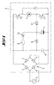
- FIG. 1 an exemplary circuit arrangement.
- This circuit arrangement is used to feed a multi-phase motor 1 here from a power supply network 2 with the interposition of a DC interposition circuit.
- the capacitor 6 is a film capacitor with a low capacitance of a few microfarads.
- an electrolytic capacitor is provided as the second capacitor 7, an electrolytic capacitor is provided. This has opposite the capacitor. 6 a much higher capacity. This is several microfarads, so on, for example, 500 uF.
- the two capacitors 6 and 7 are connected via a blocking diode 8 in such a way that only the, an input capacitor forming film capacitor 6 is effective on the network side with a view of the Oberwellnnorm uncritical small capacity.
- the free energy is passed into the second, correspondingly large electrolytic capacitor 7.
- capacitors 6 and 7 are connected by means of a resistor 9 and zener diode 10 connected in series with each other. This connected in parallel with the blocking diode 8 assembly of resistor 9 and zener diode 10 serves to reduce the voltage overshoot occurring in the input capacitor by an energy transfer in the freewheeling capacitor (electrolytic capacitor 7) during operation of the circuit on so-called soft supply networks.
- the motor 1 is driven via one of the capacitor bank downstream transistor circuit (with transistors T 1 and T 2 ) with the interposition of another blocking diode 11.
Landscapes
- Engineering & Computer Science (AREA)
- Power Engineering (AREA)
- Rectifiers (AREA)
- Control Of Motors That Do Not Use Commutators (AREA)
- Inverter Devices (AREA)
- Details Of Television Scanning (AREA)
- Dc-Dc Converters (AREA)
- Amplifiers (AREA)
Description
- Die Erfindung betrifft eine elektronische Gleichspannungs-Zwischenschaltung nach den Merkmalen des Oberbegriffes des einzeigen Anspruches.
- Bei bürstenlosen Motoren, wie beispielsweise Reluktanzmotoren, wie sie weiter zum Beispiel bei Haushaltsgeräten wie Haushaltsstaubsaugern zur Anwendung kommen, erfolgt die Speisung aus einem Gleichspannungszwischenkreis. Als Eingangsstufe für die Netzsinusspannung wird eine passive Gleichrichterbrücke eingesetzt, welche eine Elektrolytkondensatorbank auf den Scheitelwert der Eingangsspannung auflädt. Dieser Zwischenkreis kann als Speicher betrachtet werden, aus welchem der Motor über den Wechselrichter seine Energie holen und in den er seine Freilaufenergie zurückgeben kann. Die aus der Nachladung des Zwischenkreises resultierenden Oberwellen im Versorgungsnetz werden, sofern für die entsprechende Applikation Maßgaben vorliegen, mit zusätzliche PFC-Maßna1unen (bspw. Power Factor Correction Drossel) gedämpft. Ist der Zwischenkreis auf den Scheitelwert der Netzspannung aufgeladen, wird dem Netz kein Strom entnommen. Durch die Speisung des Motors aus dem Zwischenkreiskondensator wird dieser entladen, demzufolge die Zwischenkreisspannung unter den Scheitelwert der Netzspannung sinkt. Steigt nunmehr der Augenblickswert der speisenden Netzsimusspannung über dieses Spannungsniveau, beginnt der Kondensator nachzuladen, was einen sprunghaften, nicht sinusförmigen Stromanstieg im speisenden Netz zur Folge hat. Für die Amplituden der hieraus resultierenden Netzoberwellen werden durch die Norm EN 61000-3 maximal zulässige Werte vorgeschrieben. Um diese einzuhalten, ist es bekannt, die vorgenannten PFC-Maßnahmen anzuwenden.
- Eine Schaltung der in Rede stehenden Art ist aus der
US 5,115,181 bekannt. In der dort beschriebenen Schaltung sind der Gleichrichterbrücke zwei Kondensatoren unterschiedlicher Kapazitäten nachgeschaltet. - Ausgehend hiervon beschäftigt sich die Erfindung mit der Aufgabe, eine vorteilhafte elektronische Gleichspannungs-Zwischenschaltung anzugeben.
- Diese Aufgabe ist beim Gegenstand des Anspruches 1 gelöst, wobei darauf abgestellt ist, dass der Kondensator, insbesondere eine Elektrolyt-Kondensator, eine Kapazität von mindestens 50 µF aufweist, angepasst an die mögliche Freilaufenergie des Motors, dass der netzseitig wirksame Kondensator, insbesondere ein Folien-Kondensator, eine Kapazität von höchstens 500 µF aufweist, im Hinblick auf eine Einhaltung von zulässigen Werten betreffend Netzoberwellen bei einem sprunghaften, nicht sinusförmigen Stromanstieg im speisenden Netz, und dass parallel zu den Kondensatoren eine Sperrdiode vorgesehen ist und dass die Sperrdiode mit einer Zenerdiode parallel geschaltet ist. Die zwei getrennten Kondensatoren des Zwischenkreiskondensators sind derart verschaltet, dass netzseitig bevorzugt ein Folienkondensator mit einer aus Sicht der Oberwellennorm unkritisch kleinen Kapazität wirksam ist. Die Freilaufenergie wird in einen zweiten, entsprechend großen Elektrolytkondensator geleitet. Die Anordnung von Sperrdiode und Zenerdiode dient im Betrieb der Schaltung an sogenannten weichen Versorgungsnetzen zur Verringerung von auftretenden Spannungsüberhöhungen im Eingangskondensator (bevorzugt Folienkondensator mit geringer Kapazität) durch eine Energieübertragung in den Freilaufkondensator (bevorzugt Elektrolytkondensator mit hoher Kapazität). Die Freilaufenergie aus dem Motor kann aufgenommen werden, ohne im speisenden Netz Oberwellen außerhalb der Norm zu erzeugen. Auch ist eine Gewichts- und Bauraumreduzierung erreicht.
- Die beiden Kondensatoren sind in einer Parallelschaltung zwischen der netzseitigen Gleichrichterbrücke und der Ansteuerseite des Motors geschaltet, so beispielsweise vorgeschaltet einem Wechselrichter oder einer Transistorschaltung. Ein Kondensator, so bevorzugt ein Elektrolytkondensator, weist eine relativ hohe Kapazität von mehreren Mikrofarad auf, so beispielsweise mehr als 50 µF oder mehr als 250 µF, mehr als 500 µF oder mehr als 1000 µF. Die Kapazität ist an die mögliche Freilaufenergie des Motors angepasst. Der weitere Kondensator, so bevorzugt ein Folienkondensator, weist eine geringe Kapazität von wenigen Mikrofarad auf so beispielsweise weniger als 500 µF oder weniger als 250 µF oder weniger als 50 µF.
- Die relativ hohe Kapazität des einen Kondensators, bevorzugt Elektrolytkondensators, kann in weiterer Einzelheit mehr als 250µF, mehr als 500µF oder mehr als 1000µF betragen. Dies in Anpassung an die mögliche Freilaufenergie des Motors. Der weitere Kondensator, bevorzugt ein Folienkondensator, kann eine Kapazität von weniger als 250µF oder weniger als 50µF aufweisen.
- Die Erfindung ist nachstehend anhand der beigefügten Zeichnung, welche lediglich ein Ausführungsbeispiel darstellt, näher erläutert. Hierbei zeigt
Figur 1 eine beispielhafte Schaltungsanordnung. - Diese Schaltungsanordnung dient zur Speisung eines hier mehrphasigen Motors 1 aus einem Energieversorgungsnetz 2 unter Zwischenschaltung einer Gleichspamungs-Zwischenschaltung 3.
- Als Eingangsstufe für die Netzsiunusspannung ist eine aus Dioden 4 bestehende Gleichrichterbrücke 5 eingesetzt. Über diesen Zweiwrege-Brückengleichrichter werden zwei parallel geschaltete Kondensatoren 6 und 7 gespeist. Bei dem Kondensator 6 handelt es sich um einen Folienkondensator mit einer geringen Kapazität von wenigen Mikrofarad. Als zweiter Kondensator 7 ist ein Elektrolytkondensator vorgesehen. Dieser weist gegenüber dem Kondensator 6 eine wesentlich höhere Kapazität auf. Diese beträgt mehrere Mikrofarad, so weiter beispielsweise 500 µF.
- Die beiden Kondensatoren 6 und 7 sind über eine Sperrdiode 8 derart verschaltet, dass netzseitig nur der, einen Eingangskondensator bildende Folienkondensator 6 mit einer aus Sicht der Oberwellnnorm unkritisch kleinen Kapazität wirksam ist. Die Freilaufenergie wird in den zweiten, entsprechend großen Elektrolytkondensator 7 geleitet.
- Zusätzlich werden die Kondensatoren 6 und 7 über eine aus zueinander in Reihe geschalteten Widerstand 9 und Zenerdiode 10 gebildete Baugruppe verbunden. Diese parallel zur Sperrdiode 8 geschaltete Baugruppe aus Widerstand 9 und Zenerdiode 10 dient dazu, um bei Betrieb der Schaltung an sogenannten weichen Versorgungsnetzen die im Eingangskondensator durch eine Energieübertragung in den Freilaufkondensator (Elektrolytkondensator 7) auftretende Spannungsüberhöhung zu verringern.
- Der Motor 1 wird über eine der Kondensatorbank nachgeschaltete Transistorschaltung (mit Transistoren T1 und T2) unter Zwischenschaltung einer weiteren Sperrdiode 11 angesteuert.
Claims (1)
- Elektronische Gleichspannungs-Zwischenschaltung (3) zum Einsatz bei bürstenlosen Elektromotoren (1) wie beispielsweise Reluktanzmotoren, mit einer aus Dioden (4) bestehenden Gleichrichterbrücke (5), wobei der Gleichrichterbrücke (5) zwei Kondensatoren (6, 7) nachgeschaltet sind und die Kondensatoren (6, 7) unterschiedliche Kapazitäten aufweisen, dadurch gekennzeichnet, dass- der erste, netzseitige, Kondensator (6), insbesondere ein Folien-Kondensator, im Hinblick auf eine Einhaltung von zulässigen Werten betreffend Netzoberwellen bei einem sprunghaften, nicht sinusförmigen Stromanstieg im speisenden Netz eine relativ niedrige Kapazität von weniger als 500 Mikrofarad aufweist,- der zweite, motorseitige, Kondensator (7), insbesondere ein Elektrolyt-Kondensator, in seiner Größe an die mögliche Freilaufenergie des Elektromotors (1) angepasst ist und eine relativ hohe Kapazität von mehr als 50 Mikrofarad aufweist,- dass beide Kondensatoren (6, 7) über die Gleichrichterbrücke gespeist werden- und dass beide Kondensatoren über eine zueinander in Reihe geschaltete Baugruppe aus Widerstand (9) und Zenerdiode (10) verbunden sind, um bei Betrieb der Schaltung an sogenannten weichen Versorgungsnetzen im ersten, netzseitigen Eingangs-Kondensator (6) durch eine Energieübertragung in den zweiten, motorseitigen FreilaufKondensator (7) auftretende Spannungsüberhöhung zu verringern.
Applications Claiming Priority (3)
| Application Number | Priority Date | Filing Date | Title |
|---|---|---|---|
| DE102005047654 | 2005-10-05 | ||
| DE102005050278A DE102005050278A1 (de) | 2005-10-05 | 2005-10-20 | Elektronische Gleichspannungs-Zwischenschaltung |
| PCT/EP2006/066621 WO2007039487A1 (de) | 2005-10-05 | 2006-09-22 | Elektronische gleichspannungs-zwischenschaltung |
Publications (2)
| Publication Number | Publication Date |
|---|---|
| EP1943726A1 EP1943726A1 (de) | 2008-07-16 |
| EP1943726B1 true EP1943726B1 (de) | 2010-06-09 |
Family
ID=37440857
Family Applications (1)
| Application Number | Title | Priority Date | Filing Date |
|---|---|---|---|
| EP06793741A Not-in-force EP1943726B1 (de) | 2005-10-05 | 2006-09-22 | Elektronische gleichspannungs-zwischenschaltung |
Country Status (10)
| Country | Link |
|---|---|
| US (1) | US20090079368A1 (de) |
| EP (1) | EP1943726B1 (de) |
| JP (1) | JP5017273B2 (de) |
| CN (1) | CN101283504B (de) |
| AT (1) | ATE470987T1 (de) |
| DE (2) | DE102005050278A1 (de) |
| ES (1) | ES2345400T3 (de) |
| RU (1) | RU2008117394A (de) |
| TW (1) | TWI402654B (de) |
| WO (1) | WO2007039487A1 (de) |
Families Citing this family (10)
| Publication number | Priority date | Publication date | Assignee | Title |
|---|---|---|---|---|
| DE102009037723B4 (de) * | 2009-08-17 | 2016-08-11 | Siemens Aktiengesellschaft | Verfahren zum Entladen eines Zwischenkreiskondensators eines Spannungszwischenkreis-Umrichters |
| US20120134239A1 (en) * | 2010-11-28 | 2012-05-31 | Struthers Sheldon L | Micro sonic transmitter |
| US10033470B2 (en) | 2013-08-29 | 2018-07-24 | Battelle Memorial Institute | Acoustic transmission devices and process for making and using same |
| US10033469B2 (en) | 2013-08-29 | 2018-07-24 | Battelle Memorial Institute | Injectable acoustic transmission devices and process for making and using same |
| US10101429B2 (en) * | 2015-02-25 | 2018-10-16 | Battelle Memorial Institute | Acoustic transmission device and process for tracking selected hosts |
| US10067112B2 (en) | 2015-09-30 | 2018-09-04 | Battelle Memorial Institute | Autonomous sensor fish to support advanced hydropower development |
| US10236920B2 (en) | 2015-12-15 | 2019-03-19 | Battelle Memorial Institute | Signal transmitter and methods for transmitting signals from animals |
| US11278004B2 (en) | 2015-12-15 | 2022-03-22 | Battelle Memorial Institute | Transmitters for animals and methods for transmitting from animals |
| US10531639B2 (en) | 2016-08-25 | 2020-01-14 | Battelle Memorial Institute | Systems and methods for monitoring organisms within an aquatic environment |
| US11533818B2 (en) | 2019-03-12 | 2022-12-20 | Battelle Memorial Institute | Sensor assemblies and methods for emulating interaction of entities within water systems |
Family Cites Families (13)
| Publication number | Priority date | Publication date | Assignee | Title |
|---|---|---|---|---|
| US4227029A (en) * | 1978-05-15 | 1980-10-07 | Brockway Glass Company, Inc. | Method and apparatus for eliminating D.C. in an electric glass melting furnace |
| US5115181A (en) * | 1990-10-05 | 1992-05-19 | Emerson Electric Co. | Power converter for a switched reluctance motor |
| US5103148A (en) * | 1990-11-06 | 1992-04-07 | Motorola, Inc. | Low voltage circuit to control high voltage transistor |
| JP3278188B2 (ja) * | 1992-03-16 | 2002-04-30 | 勲 高橋 | 電動機駆動用インバータ装置 |
| JPH0686561A (ja) * | 1992-06-26 | 1994-03-25 | Toshiba Lighting & Technol Corp | 電源装置、放電灯点灯装置および照明装置 |
| JPH06113525A (ja) * | 1992-09-29 | 1994-04-22 | Fuji Electric Co Ltd | スナバ回路 |
| KR100189500B1 (ko) * | 1996-01-29 | 1999-06-01 | 구자홍 | 스위치드 릴럭턴스 모터(srm)의 컨버터 |
| US6160389A (en) * | 1999-08-27 | 2000-12-12 | Black & Decker Inc. | Battery charger with low heat dissipation |
| DE60002711T2 (de) * | 2000-06-21 | 2004-03-25 | Magnetek S.P.A. | Bürstenloser Motor, Verfahren und Schaltung zu seiner Regelung |
| TWI237440B (en) * | 2001-10-17 | 2005-08-01 | Prolific Technology Inc | AC brushless motor controlling device driven by AC/DC |
| CN2509776Y (zh) * | 2001-11-12 | 2002-09-04 | 元山科技工业股份有限公司 | 直流无刷风扇电动机的电源控制电路 |
| JP3981886B2 (ja) * | 2003-03-11 | 2007-09-26 | 株式会社デンソー | 整流回路 |
| US6924612B2 (en) * | 2003-12-08 | 2005-08-02 | Molon Motor & Coil Corporation | Three-wire reversing system |
-
2005
- 2005-10-20 DE DE102005050278A patent/DE102005050278A1/de not_active Withdrawn
-
2006
- 2006-09-22 AT AT06793741T patent/ATE470987T1/de active
- 2006-09-22 WO PCT/EP2006/066621 patent/WO2007039487A1/de not_active Ceased
- 2006-09-22 DE DE502006007196T patent/DE502006007196D1/de active Active
- 2006-09-22 ES ES06793741T patent/ES2345400T3/es active Active
- 2006-09-22 JP JP2008533968A patent/JP5017273B2/ja not_active Expired - Fee Related
- 2006-09-22 RU RU2008117394/09A patent/RU2008117394A/ru not_active Application Discontinuation
- 2006-09-22 US US11/992,982 patent/US20090079368A1/en not_active Abandoned
- 2006-09-22 EP EP06793741A patent/EP1943726B1/de not_active Not-in-force
- 2006-09-22 CN CN200680037077XA patent/CN101283504B/zh not_active Expired - Fee Related
- 2006-09-28 TW TW095135974A patent/TWI402654B/zh not_active IP Right Cessation
Also Published As
| Publication number | Publication date |
|---|---|
| CN101283504B (zh) | 2011-03-16 |
| TW200720876A (en) | 2007-06-01 |
| WO2007039487A1 (de) | 2007-04-12 |
| JP5017273B2 (ja) | 2012-09-05 |
| EP1943726A1 (de) | 2008-07-16 |
| US20090079368A1 (en) | 2009-03-26 |
| ATE470987T1 (de) | 2010-06-15 |
| JP2009512407A (ja) | 2009-03-19 |
| RU2008117394A (ru) | 2009-11-10 |
| DE102005050278A1 (de) | 2007-04-12 |
| TWI402654B (zh) | 2013-07-21 |
| ES2345400T3 (es) | 2010-09-22 |
| DE502006007196D1 (de) | 2010-07-22 |
| CN101283504A (zh) | 2008-10-08 |
Similar Documents
| Publication | Publication Date | Title |
|---|---|---|
| DE69623394T2 (de) | Schaltkreis und Verfahren zum Steuerung eines Einschaltstrombegrenzers in ein Leistungswandler mit Leistungsfaktorkorrektur | |
| DE69117008T2 (de) | Wechselrichteranordnung | |
| DE69008651T2 (de) | Dämpferschaltung eines Leistungswandlers. | |
| DE19901930B4 (de) | Schaltnetzteil | |
| DE102008034357A1 (de) | Spannungsverbindungssteuerung eines DC/AC-Aufwärts-Wandlersystems | |
| DE10155182A1 (de) | Verfahren und Vorrichtung zur Leistungsumwandlung elektrischer Energie | |
| DE102018109769A1 (de) | Wandlervorrichtung, die die Initialladezeit eines Gleichstromzwischenkreis-Kondensators optimiert | |
| DE102018216236A1 (de) | Ladeschaltung für einen fahrzeugseitigen elektrischen Energiespeicher | |
| EP2254224A1 (de) | Verfahren zum Entladen einer Entstörkapazität am Ausgang einer Wechselrichtereinrichtung und Wechselrichtereinrichtung | |
| EP1943726A1 (de) | Elektronische gleichspannungs-zwischenschaltung | |
| DE10062075A1 (de) | Umrichter mit integrierten Zwischenkreiskondensatoren | |
| EP1508962B1 (de) | Spannungszwischenkreis-Umrichter | |
| DE102013105098B4 (de) | Integrierter Solar-/Batteriewechselrichter | |
| EP1249066B1 (de) | Elektrogerät mit einem Elektromotor und einem Drosselwandler | |
| DE102013102433A1 (de) | Wechselrichter für eine variable Eingangsgleichspannung | |
| DE202008015578U1 (de) | Kapazitives Netzgerät | |
| EP2826126B1 (de) | Leistungselektronische anordnung mit symmetrierung eines spannungsknotens im zwischenkreis | |
| WO2020064429A1 (de) | Ladeschaltung für einen fahrzeugseitigen elektrischen energiespeicher | |
| EP2582201A1 (de) | Induktionsheizvorrichtung | |
| DE69114982T2 (de) | Stromversorgungskreis. | |
| DE19825801C2 (de) | Gleichspannungs-Zwischenkreis mit Hochlast-Widerstand | |
| DE1918183A1 (de) | Wechselrichter fuer induktive Verbraucher und Verwendung desselben als Frequenzwandler | |
| DE102018209139B4 (de) | Wechselspannungs-Ladevorrichtung | |
| DE102019205946A1 (de) | Filterschaltung zum Reduzieren von Rückwirkungen eines Verbrauchers auf eine Energieversorgung | |
| DE3418020C2 (de) | Schaltungsanordnung zur Spannungsbegrenzung eines von einem stromeinprägenden Umrichter gespeisten Motors |
Legal Events
| Date | Code | Title | Description |
|---|---|---|---|
| PUAI | Public reference made under article 153(3) epc to a published international application that has entered the european phase |
Free format text: ORIGINAL CODE: 0009012 |
|
| 17P | Request for examination filed |
Effective date: 20080327 |
|
| AK | Designated contracting states |
Kind code of ref document: A1 Designated state(s): AT BE BG CH CY CZ DE DK EE ES FI FR GB GR HU IE IS IT LI LT LU LV MC NL PL PT RO SE SI SK TR |
|
| RIN1 | Information on inventor provided before grant (corrected) |
Inventor name: POPPEN, GUENTER Inventor name: LANG, TORSTEN Inventor name: CALDEWEY, UWE |
|
| 17Q | First examination report despatched |
Effective date: 20080902 |
|
| GRAP | Despatch of communication of intention to grant a patent |
Free format text: ORIGINAL CODE: EPIDOSNIGR1 |
|
| GRAS | Grant fee paid |
Free format text: ORIGINAL CODE: EPIDOSNIGR3 |
|
| GRAA | (expected) grant |
Free format text: ORIGINAL CODE: 0009210 |
|
| AK | Designated contracting states |
Kind code of ref document: B1 Designated state(s): AT BE BG CH CY CZ DE DK EE ES FI FR GB GR HU IE IS IT LI LT LU LV MC NL PL PT RO SE SI SK TR |
|
| REG | Reference to a national code |
Ref country code: CH Ref legal event code: EP |
|
| REG | Reference to a national code |
Ref country code: IE Ref legal event code: FG4D Free format text: LANGUAGE OF EP DOCUMENT: GERMAN |
|
| REF | Corresponds to: |
Ref document number: 502006007196 Country of ref document: DE Date of ref document: 20100722 Kind code of ref document: P |
|
| REG | Reference to a national code |
Ref country code: ES Ref legal event code: FG2A Ref document number: 2345400 Country of ref document: ES Kind code of ref document: T3 |
|
| REG | Reference to a national code |
Ref country code: NL Ref legal event code: VDEP Effective date: 20100609 |
|
| PG25 | Lapsed in a contracting state [announced via postgrant information from national office to epo] |
Ref country code: LT Free format text: LAPSE BECAUSE OF FAILURE TO SUBMIT A TRANSLATION OF THE DESCRIPTION OR TO PAY THE FEE WITHIN THE PRESCRIBED TIME-LIMIT Effective date: 20100609 Ref country code: SE Free format text: LAPSE BECAUSE OF FAILURE TO SUBMIT A TRANSLATION OF THE DESCRIPTION OR TO PAY THE FEE WITHIN THE PRESCRIBED TIME-LIMIT Effective date: 20100609 |
|
| LTIE | Lt: invalidation of european patent or patent extension |
Effective date: 20100609 |
|
| PG25 | Lapsed in a contracting state [announced via postgrant information from national office to epo] |
Ref country code: LV Free format text: LAPSE BECAUSE OF FAILURE TO SUBMIT A TRANSLATION OF THE DESCRIPTION OR TO PAY THE FEE WITHIN THE PRESCRIBED TIME-LIMIT Effective date: 20100609 Ref country code: SI Free format text: LAPSE BECAUSE OF FAILURE TO SUBMIT A TRANSLATION OF THE DESCRIPTION OR TO PAY THE FEE WITHIN THE PRESCRIBED TIME-LIMIT Effective date: 20100609 Ref country code: FI Free format text: LAPSE BECAUSE OF FAILURE TO SUBMIT A TRANSLATION OF THE DESCRIPTION OR TO PAY THE FEE WITHIN THE PRESCRIBED TIME-LIMIT Effective date: 20100609 |
|
| PG25 | Lapsed in a contracting state [announced via postgrant information from national office to epo] |
Ref country code: CY Free format text: LAPSE BECAUSE OF FAILURE TO SUBMIT A TRANSLATION OF THE DESCRIPTION OR TO PAY THE FEE WITHIN THE PRESCRIBED TIME-LIMIT Effective date: 20100609 Ref country code: GR Free format text: LAPSE BECAUSE OF FAILURE TO SUBMIT A TRANSLATION OF THE DESCRIPTION OR TO PAY THE FEE WITHIN THE PRESCRIBED TIME-LIMIT Effective date: 20100910 Ref country code: PL Free format text: LAPSE BECAUSE OF FAILURE TO SUBMIT A TRANSLATION OF THE DESCRIPTION OR TO PAY THE FEE WITHIN THE PRESCRIBED TIME-LIMIT Effective date: 20100609 |
|
| REG | Reference to a national code |
Ref country code: IE Ref legal event code: FD4D |
|
| PG25 | Lapsed in a contracting state [announced via postgrant information from national office to epo] |
Ref country code: NL Free format text: LAPSE BECAUSE OF FAILURE TO SUBMIT A TRANSLATION OF THE DESCRIPTION OR TO PAY THE FEE WITHIN THE PRESCRIBED TIME-LIMIT Effective date: 20100609 Ref country code: EE Free format text: LAPSE BECAUSE OF FAILURE TO SUBMIT A TRANSLATION OF THE DESCRIPTION OR TO PAY THE FEE WITHIN THE PRESCRIBED TIME-LIMIT Effective date: 20100609 Ref country code: IE Free format text: LAPSE BECAUSE OF FAILURE TO SUBMIT A TRANSLATION OF THE DESCRIPTION OR TO PAY THE FEE WITHIN THE PRESCRIBED TIME-LIMIT Effective date: 20100609 |
|
| PG25 | Lapsed in a contracting state [announced via postgrant information from national office to epo] |
Ref country code: SK Free format text: LAPSE BECAUSE OF FAILURE TO SUBMIT A TRANSLATION OF THE DESCRIPTION OR TO PAY THE FEE WITHIN THE PRESCRIBED TIME-LIMIT Effective date: 20100609 Ref country code: IS Free format text: LAPSE BECAUSE OF FAILURE TO SUBMIT A TRANSLATION OF THE DESCRIPTION OR TO PAY THE FEE WITHIN THE PRESCRIBED TIME-LIMIT Effective date: 20101009 Ref country code: PT Free format text: LAPSE BECAUSE OF FAILURE TO SUBMIT A TRANSLATION OF THE DESCRIPTION OR TO PAY THE FEE WITHIN THE PRESCRIBED TIME-LIMIT Effective date: 20101011 Ref country code: RO Free format text: LAPSE BECAUSE OF FAILURE TO SUBMIT A TRANSLATION OF THE DESCRIPTION OR TO PAY THE FEE WITHIN THE PRESCRIBED TIME-LIMIT Effective date: 20100609 |
|
| BERE | Be: lapsed |
Owner name: VORWERK & CO. INTERHOLDING G.M.B.H. Effective date: 20100930 |
|
| PLBE | No opposition filed within time limit |
Free format text: ORIGINAL CODE: 0009261 |
|
| STAA | Information on the status of an ep patent application or granted ep patent |
Free format text: STATUS: NO OPPOSITION FILED WITHIN TIME LIMIT |
|
| PG25 | Lapsed in a contracting state [announced via postgrant information from national office to epo] |
Ref country code: DK Free format text: LAPSE BECAUSE OF FAILURE TO SUBMIT A TRANSLATION OF THE DESCRIPTION OR TO PAY THE FEE WITHIN THE PRESCRIBED TIME-LIMIT Effective date: 20100609 Ref country code: MC Free format text: LAPSE BECAUSE OF NON-PAYMENT OF DUE FEES Effective date: 20100930 |
|
| REG | Reference to a national code |
Ref country code: CH Ref legal event code: PL |
|
| GBPC | Gb: european patent ceased through non-payment of renewal fee |
Effective date: 20100922 |
|
| REG | Reference to a national code |
Ref country code: DE Ref legal event code: R097 Ref document number: 502006007196 Country of ref document: DE Effective date: 20110309 |
|
| PG25 | Lapsed in a contracting state [announced via postgrant information from national office to epo] |
Ref country code: BE Free format text: LAPSE BECAUSE OF NON-PAYMENT OF DUE FEES Effective date: 20100930 Ref country code: LI Free format text: LAPSE BECAUSE OF NON-PAYMENT OF DUE FEES Effective date: 20100930 Ref country code: CH Free format text: LAPSE BECAUSE OF NON-PAYMENT OF DUE FEES Effective date: 20100930 |
|
| PG25 | Lapsed in a contracting state [announced via postgrant information from national office to epo] |
Ref country code: GB Free format text: LAPSE BECAUSE OF NON-PAYMENT OF DUE FEES Effective date: 20100922 |
|
| PG25 | Lapsed in a contracting state [announced via postgrant information from national office to epo] |
Ref country code: HU Free format text: LAPSE BECAUSE OF FAILURE TO SUBMIT A TRANSLATION OF THE DESCRIPTION OR TO PAY THE FEE WITHIN THE PRESCRIBED TIME-LIMIT Effective date: 20101210 Ref country code: LU Free format text: LAPSE BECAUSE OF NON-PAYMENT OF DUE FEES Effective date: 20100922 Ref country code: BG Free format text: LAPSE BECAUSE OF FAILURE TO SUBMIT A TRANSLATION OF THE DESCRIPTION OR TO PAY THE FEE WITHIN THE PRESCRIBED TIME-LIMIT Effective date: 20100609 |
|
| PG25 | Lapsed in a contracting state [announced via postgrant information from national office to epo] |
Ref country code: TR Free format text: LAPSE BECAUSE OF FAILURE TO SUBMIT A TRANSLATION OF THE DESCRIPTION OR TO PAY THE FEE WITHIN THE PRESCRIBED TIME-LIMIT Effective date: 20100609 |
|
| PG25 | Lapsed in a contracting state [announced via postgrant information from national office to epo] |
Ref country code: BG Free format text: LAPSE BECAUSE OF FAILURE TO SUBMIT A TRANSLATION OF THE DESCRIPTION OR TO PAY THE FEE WITHIN THE PRESCRIBED TIME-LIMIT Effective date: 20100909 |
|
| REG | Reference to a national code |
Ref country code: FR Ref legal event code: PLFP Year of fee payment: 11 |
|
| REG | Reference to a national code |
Ref country code: FR Ref legal event code: PLFP Year of fee payment: 12 |
|
| REG | Reference to a national code |
Ref country code: FR Ref legal event code: PLFP Year of fee payment: 13 |
|
| PGFP | Annual fee paid to national office [announced via postgrant information from national office to epo] |
Ref country code: IT Payment date: 20180921 Year of fee payment: 13 Ref country code: FR Payment date: 20180921 Year of fee payment: 13 Ref country code: DE Payment date: 20180924 Year of fee payment: 13 |
|
| PGFP | Annual fee paid to national office [announced via postgrant information from national office to epo] |
Ref country code: AT Payment date: 20180918 Year of fee payment: 13 Ref country code: CZ Payment date: 20180906 Year of fee payment: 13 |
|
| PGFP | Annual fee paid to national office [announced via postgrant information from national office to epo] |
Ref country code: ES Payment date: 20181024 Year of fee payment: 13 |
|
| REG | Reference to a national code |
Ref country code: DE Ref legal event code: R119 Ref document number: 502006007196 Country of ref document: DE |
|
| PG25 | Lapsed in a contracting state [announced via postgrant information from national office to epo] |
Ref country code: CZ Free format text: LAPSE BECAUSE OF NON-PAYMENT OF DUE FEES Effective date: 20190922 |
|
| PG25 | Lapsed in a contracting state [announced via postgrant information from national office to epo] |
Ref country code: DE Free format text: LAPSE BECAUSE OF NON-PAYMENT OF DUE FEES Effective date: 20200401 |
|
| REG | Reference to a national code |
Ref country code: AT Ref legal event code: MM01 Ref document number: 470987 Country of ref document: AT Kind code of ref document: T Effective date: 20190922 |
|
| PG25 | Lapsed in a contracting state [announced via postgrant information from national office to epo] |
Ref country code: IT Free format text: LAPSE BECAUSE OF NON-PAYMENT OF DUE FEES Effective date: 20190922 |
|
| PG25 | Lapsed in a contracting state [announced via postgrant information from national office to epo] |
Ref country code: FR Free format text: LAPSE BECAUSE OF NON-PAYMENT OF DUE FEES Effective date: 20190930 |
|
| PG25 | Lapsed in a contracting state [announced via postgrant information from national office to epo] |
Ref country code: AT Free format text: LAPSE BECAUSE OF NON-PAYMENT OF DUE FEES Effective date: 20190922 |
|
| REG | Reference to a national code |
Ref country code: ES Ref legal event code: FD2A Effective date: 20210128 |
|
| PG25 | Lapsed in a contracting state [announced via postgrant information from national office to epo] |
Ref country code: ES Free format text: LAPSE BECAUSE OF NON-PAYMENT OF DUE FEES Effective date: 20190923 |