EP1943413B1 - Vorrichtung und verfahren zur aerosoltrennung - Google Patents
Vorrichtung und verfahren zur aerosoltrennung Download PDFInfo
- Publication number
- EP1943413B1 EP1943413B1 EP06826711A EP06826711A EP1943413B1 EP 1943413 B1 EP1943413 B1 EP 1943413B1 EP 06826711 A EP06826711 A EP 06826711A EP 06826711 A EP06826711 A EP 06826711A EP 1943413 B1 EP1943413 B1 EP 1943413B1
- Authority
- EP
- European Patent Office
- Prior art keywords
- media
- crankcase ventilation
- end cap
- filter cartridge
- cartridge according
- Prior art date
- Legal status (The legal status is an assumption and is not a legal conclusion. Google has not performed a legal analysis and makes no representation as to the accuracy of the status listed.)
- Active
Links
- 238000000034 method Methods 0.000 title claims description 21
- 239000000443 aerosol Substances 0.000 title description 7
- 239000000835 fiber Substances 0.000 claims description 121
- 239000007789 gas Substances 0.000 claims description 73
- 239000000463 material Substances 0.000 claims description 68
- 238000009423 ventilation Methods 0.000 claims description 62
- 239000007788 liquid Substances 0.000 claims description 57
- 238000001914 filtration Methods 0.000 claims description 32
- 239000011148 porous material Substances 0.000 claims description 30
- 239000011230 binding agent Substances 0.000 claims description 11
- 239000002657 fibrous material Substances 0.000 claims description 11
- 229920005989 resin Polymers 0.000 claims description 10
- 239000011347 resin Substances 0.000 claims description 10
- 238000007789 sealing Methods 0.000 claims description 6
- 229920005830 Polyurethane Foam Polymers 0.000 claims description 5
- 239000011324 bead Substances 0.000 claims description 5
- 239000011496 polyurethane foam Substances 0.000 claims description 5
- 238000004891 communication Methods 0.000 claims description 4
- 238000011144 upstream manufacturing Methods 0.000 claims description 4
- 238000007906 compression Methods 0.000 description 20
- 230000006835 compression Effects 0.000 description 20
- -1 polyethylene Polymers 0.000 description 17
- 229920000728 polyester Polymers 0.000 description 15
- 239000002245 particle Substances 0.000 description 14
- 239000000203 mixture Substances 0.000 description 12
- 229920000642 polymer Polymers 0.000 description 12
- 238000010276 construction Methods 0.000 description 11
- 238000002844 melting Methods 0.000 description 11
- 230000008018 melting Effects 0.000 description 11
- 238000002485 combustion reaction Methods 0.000 description 9
- 239000003921 oil Substances 0.000 description 9
- 239000012530 fluid Substances 0.000 description 8
- 239000003365 glass fiber Substances 0.000 description 8
- 229920001778 nylon Polymers 0.000 description 8
- 230000008569 process Effects 0.000 description 8
- 238000012360 testing method Methods 0.000 description 8
- XLYOFNOQVPJJNP-UHFFFAOYSA-N water Substances O XLYOFNOQVPJJNP-UHFFFAOYSA-N 0.000 description 8
- 230000002209 hydrophobic effect Effects 0.000 description 7
- 229910052751 metal Inorganic materials 0.000 description 7
- 239000002184 metal Substances 0.000 description 7
- 239000004677 Nylon Substances 0.000 description 6
- 239000000356 contaminant Substances 0.000 description 6
- 229920003023 plastic Polymers 0.000 description 6
- 239000004033 plastic Substances 0.000 description 6
- 229920002635 polyurethane Polymers 0.000 description 6
- 239000004814 polyurethane Substances 0.000 description 6
- 239000002002 slurry Substances 0.000 description 6
- OKTJSMMVPCPJKN-UHFFFAOYSA-N Carbon Chemical compound [C] OKTJSMMVPCPJKN-UHFFFAOYSA-N 0.000 description 5
- 239000011521 glass Substances 0.000 description 5
- 230000035699 permeability Effects 0.000 description 5
- 229920000098 polyolefin Polymers 0.000 description 5
- 238000000926 separation method Methods 0.000 description 5
- 229920001169 thermoplastic Polymers 0.000 description 5
- 239000004698 Polyethylene Substances 0.000 description 4
- 239000004743 Polypropylene Substances 0.000 description 4
- 239000004372 Polyvinyl alcohol Substances 0.000 description 4
- 230000000712 assembly Effects 0.000 description 4
- 238000000429 assembly Methods 0.000 description 4
- 230000008901 benefit Effects 0.000 description 4
- 229910052799 carbon Inorganic materials 0.000 description 4
- 239000000446 fuel Substances 0.000 description 4
- 230000005484 gravity Effects 0.000 description 4
- 239000012948 isocyanate Substances 0.000 description 4
- 150000002513 isocyanates Chemical class 0.000 description 4
- 238000004519 manufacturing process Methods 0.000 description 4
- 229920000573 polyethylene Polymers 0.000 description 4
- 229920001155 polypropylene Polymers 0.000 description 4
- 229920001296 polysiloxane Polymers 0.000 description 4
- 229920002451 polyvinyl alcohol Polymers 0.000 description 4
- 239000004416 thermosoftening plastic Substances 0.000 description 4
- 238000011282 treatment Methods 0.000 description 4
- 229920002302 Nylon 6,6 Polymers 0.000 description 3
- 239000004952 Polyamide Substances 0.000 description 3
- 238000011161 development Methods 0.000 description 3
- 230000018109 developmental process Effects 0.000 description 3
- 238000006073 displacement reaction Methods 0.000 description 3
- 230000003993 interaction Effects 0.000 description 3
- 239000013028 medium composition Substances 0.000 description 3
- 239000012071 phase Substances 0.000 description 3
- 230000000704 physical effect Effects 0.000 description 3
- 229920002647 polyamide Polymers 0.000 description 3
- 239000005020 polyethylene terephthalate Substances 0.000 description 3
- 229920000139 polyethylene terephthalate Polymers 0.000 description 3
- 229920002689 polyvinyl acetate Polymers 0.000 description 3
- 239000011118 polyvinyl acetate Substances 0.000 description 3
- 229920000742 Cotton Polymers 0.000 description 2
- JOYRKODLDBILNP-UHFFFAOYSA-N Ethyl urethane Chemical compound CCOC(N)=O JOYRKODLDBILNP-UHFFFAOYSA-N 0.000 description 2
- XEEYBQQBJWHFJM-UHFFFAOYSA-N Iron Chemical compound [Fe] XEEYBQQBJWHFJM-UHFFFAOYSA-N 0.000 description 2
- 229920000106 Liquid crystal polymer Polymers 0.000 description 2
- 229920001410 Microfiber Polymers 0.000 description 2
- 229920002292 Nylon 6 Polymers 0.000 description 2
- 239000004696 Poly ether ether ketone Substances 0.000 description 2
- 229920000297 Rayon Polymers 0.000 description 2
- 238000013459 approach Methods 0.000 description 2
- 239000000919 ceramic Substances 0.000 description 2
- 230000008859 change Effects 0.000 description 2
- 229920001577 copolymer Polymers 0.000 description 2
- 238000009434 installation Methods 0.000 description 2
- 239000007791 liquid phase Substances 0.000 description 2
- 239000011159 matrix material Substances 0.000 description 2
- 239000003658 microfiber Substances 0.000 description 2
- 229920001652 poly(etherketoneketone) Polymers 0.000 description 2
- 229920001707 polybutylene terephthalate Polymers 0.000 description 2
- 229920002530 polyetherether ketone Polymers 0.000 description 2
- 239000004800 polyvinyl chloride Substances 0.000 description 2
- 229920000915 polyvinyl chloride Polymers 0.000 description 2
- 238000012545 processing Methods 0.000 description 2
- 239000007787 solid Substances 0.000 description 2
- 239000000126 substance Substances 0.000 description 2
- 238000004381 surface treatment Methods 0.000 description 2
- 239000012815 thermoplastic material Substances 0.000 description 2
- QTBSBXVTEAMEQO-UHFFFAOYSA-M Acetate Chemical compound CC([O-])=O QTBSBXVTEAMEQO-UHFFFAOYSA-M 0.000 description 1
- 229920000178 Acrylic resin Polymers 0.000 description 1
- 239000004925 Acrylic resin Substances 0.000 description 1
- 241000531908 Aramides Species 0.000 description 1
- 239000004604 Blowing Agent Substances 0.000 description 1
- VYZAMTAEIAYCRO-UHFFFAOYSA-N Chromium Chemical compound [Cr] VYZAMTAEIAYCRO-UHFFFAOYSA-N 0.000 description 1
- RYGMFSIKBFXOCR-UHFFFAOYSA-N Copper Chemical compound [Cu] RYGMFSIKBFXOCR-UHFFFAOYSA-N 0.000 description 1
- ZZSNKZQZMQGXPY-UHFFFAOYSA-N Ethyl cellulose Chemical compound CCOCC1OC(OC)C(OCC)C(OCC)C1OC1C(O)C(O)C(OC)C(CO)O1 ZZSNKZQZMQGXPY-UHFFFAOYSA-N 0.000 description 1
- 239000001856 Ethyl cellulose Substances 0.000 description 1
- DGAQECJNVWCQMB-PUAWFVPOSA-M Ilexoside XXIX Chemical compound C[C@@H]1CC[C@@]2(CC[C@@]3(C(=CC[C@H]4[C@]3(CC[C@@H]5[C@@]4(CC[C@@H](C5(C)C)OS(=O)(=O)[O-])C)C)[C@@H]2[C@]1(C)O)C)C(=O)O[C@H]6[C@@H]([C@H]([C@@H]([C@H](O6)CO)O)O)O.[Na+] DGAQECJNVWCQMB-PUAWFVPOSA-M 0.000 description 1
- 229920002633 Kraton (polymer) Polymers 0.000 description 1
- ZOKXTWBITQBERF-UHFFFAOYSA-N Molybdenum Chemical compound [Mo] ZOKXTWBITQBERF-UHFFFAOYSA-N 0.000 description 1
- 229910002651 NO3 Inorganic materials 0.000 description 1
- NHNBFGGVMKEFGY-UHFFFAOYSA-N Nitrate Chemical compound [O-][N+]([O-])=O NHNBFGGVMKEFGY-UHFFFAOYSA-N 0.000 description 1
- 229920000571 Nylon 11 Polymers 0.000 description 1
- 229920000299 Nylon 12 Polymers 0.000 description 1
- 229920003189 Nylon 4,6 Polymers 0.000 description 1
- 229920000572 Nylon 6/12 Polymers 0.000 description 1
- 229920002319 Poly(methyl acrylate) Polymers 0.000 description 1
- 239000004721 Polyphenylene oxide Substances 0.000 description 1
- 239000004793 Polystyrene Substances 0.000 description 1
- 229920001756 Polyvinyl chloride acetate Polymers 0.000 description 1
- 229920001328 Polyvinylidene chloride Polymers 0.000 description 1
- 241000283068 Tapiridae Species 0.000 description 1
- ATJFFYVFTNAWJD-UHFFFAOYSA-N Tin Chemical compound [Sn] ATJFFYVFTNAWJD-UHFFFAOYSA-N 0.000 description 1
- 238000010521 absorption reaction Methods 0.000 description 1
- 238000009825 accumulation Methods 0.000 description 1
- UGZICOVULPINFH-UHFFFAOYSA-N acetic acid;butanoic acid Chemical compound CC(O)=O.CCCC(O)=O UGZICOVULPINFH-UHFFFAOYSA-N 0.000 description 1
- NIXOWILDQLNWCW-UHFFFAOYSA-N acrylic acid group Chemical group C(C=C)(=O)O NIXOWILDQLNWCW-UHFFFAOYSA-N 0.000 description 1
- 230000032683 aging Effects 0.000 description 1
- 229910052782 aluminium Inorganic materials 0.000 description 1
- XAGFODPZIPBFFR-UHFFFAOYSA-N aluminium Chemical compound [Al] XAGFODPZIPBFFR-UHFFFAOYSA-N 0.000 description 1
- 150000001412 amines Chemical class 0.000 description 1
- 229920003235 aromatic polyamide Polymers 0.000 description 1
- 230000004323 axial length Effects 0.000 description 1
- 230000015572 biosynthetic process Effects 0.000 description 1
- 238000009835 boiling Methods 0.000 description 1
- 239000006229 carbon black Substances 0.000 description 1
- 239000003575 carbonaceous material Substances 0.000 description 1
- 239000012159 carrier gas Substances 0.000 description 1
- 239000003054 catalyst Substances 0.000 description 1
- 239000007795 chemical reaction product Substances 0.000 description 1
- 229910052804 chromium Inorganic materials 0.000 description 1
- 239000011651 chromium Substances 0.000 description 1
- 239000000567 combustion gas Substances 0.000 description 1
- 239000000470 constituent Substances 0.000 description 1
- 238000001816 cooling Methods 0.000 description 1
- 229910052802 copper Inorganic materials 0.000 description 1
- 239000010949 copper Substances 0.000 description 1
- 238000004132 cross linking Methods 0.000 description 1
- 238000013461 design Methods 0.000 description 1
- 150000002009 diols Chemical class 0.000 description 1
- 238000010130 dispersion processing Methods 0.000 description 1
- 239000000975 dye Substances 0.000 description 1
- 229920001971 elastomer Polymers 0.000 description 1
- 229920001249 ethyl cellulose Polymers 0.000 description 1
- 235000019325 ethyl cellulose Nutrition 0.000 description 1
- 229920006242 ethylene acrylic acid copolymer Polymers 0.000 description 1
- 238000011156 evaluation Methods 0.000 description 1
- 238000009472 formulation Methods 0.000 description 1
- 229910002804 graphite Inorganic materials 0.000 description 1
- 239000010439 graphite Substances 0.000 description 1
- 238000010438 heat treatment Methods 0.000 description 1
- 229910001385 heavy metal Inorganic materials 0.000 description 1
- 230000007062 hydrolysis Effects 0.000 description 1
- 238000006460 hydrolysis reaction Methods 0.000 description 1
- 125000002887 hydroxy group Chemical group [H]O* 0.000 description 1
- 238000012994 industrial processing Methods 0.000 description 1
- 239000012784 inorganic fiber Substances 0.000 description 1
- 238000009413 insulation Methods 0.000 description 1
- 229910052742 iron Inorganic materials 0.000 description 1
- 239000008263 liquid aerosol Substances 0.000 description 1
- 238000011068 loading method Methods 0.000 description 1
- 238000005259 measurement Methods 0.000 description 1
- 239000000155 melt Substances 0.000 description 1
- 238000002156 mixing Methods 0.000 description 1
- 238000012986 modification Methods 0.000 description 1
- 230000004048 modification Effects 0.000 description 1
- 239000013518 molded foam Substances 0.000 description 1
- 239000002991 molded plastic Substances 0.000 description 1
- 229910052750 molybdenum Inorganic materials 0.000 description 1
- 239000011733 molybdenum Substances 0.000 description 1
- 238000000465 moulding Methods 0.000 description 1
- 230000000737 periodic effect Effects 0.000 description 1
- XNGIFLGASWRNHJ-UHFFFAOYSA-L phthalate(2-) Chemical compound [O-]C(=O)C1=CC=CC=C1C([O-])=O XNGIFLGASWRNHJ-UHFFFAOYSA-L 0.000 description 1
- 239000000049 pigment Substances 0.000 description 1
- 229920001200 poly(ethylene-vinyl acetate) Polymers 0.000 description 1
- 229920000747 poly(lactic acid) Polymers 0.000 description 1
- 229920003229 poly(methyl methacrylate) Polymers 0.000 description 1
- 229920002037 poly(vinyl butyral) polymer Polymers 0.000 description 1
- 229920000058 polyacrylate Polymers 0.000 description 1
- 229920001748 polybutylene Polymers 0.000 description 1
- 229920000570 polyether Polymers 0.000 description 1
- 239000004626 polylactic acid Substances 0.000 description 1
- 239000004926 polymethyl methacrylate Substances 0.000 description 1
- 229920005862 polyol Polymers 0.000 description 1
- 150000003077 polyols Chemical class 0.000 description 1
- 229920002223 polystyrene Polymers 0.000 description 1
- 229920001343 polytetrafluoroethylene Polymers 0.000 description 1
- 239000004810 polytetrafluoroethylene Substances 0.000 description 1
- 229920005749 polyurethane resin Polymers 0.000 description 1
- 239000005033 polyvinylidene chloride Substances 0.000 description 1
- 238000002360 preparation method Methods 0.000 description 1
- 239000000047 product Substances 0.000 description 1
- 230000002035 prolonged effect Effects 0.000 description 1
- 239000002964 rayon Substances 0.000 description 1
- 230000002787 reinforcement Effects 0.000 description 1
- 239000005060 rubber Substances 0.000 description 1
- 229910052708 sodium Inorganic materials 0.000 description 1
- 239000011734 sodium Substances 0.000 description 1
- 238000009987 spinning Methods 0.000 description 1
- 230000035882 stress Effects 0.000 description 1
- 229920003048 styrene butadiene rubber Polymers 0.000 description 1
- 239000012756 surface treatment agent Substances 0.000 description 1
- 239000004094 surface-active agent Substances 0.000 description 1
- 229920002994 synthetic fiber Polymers 0.000 description 1
- 239000012209 synthetic fiber Substances 0.000 description 1
- 229920002803 thermoplastic polyurethane Polymers 0.000 description 1
- 229910052718 tin Inorganic materials 0.000 description 1
- 239000011135 tin Substances 0.000 description 1
- 150000004072 triols Chemical class 0.000 description 1
- 210000002268 wool Anatomy 0.000 description 1
Images


Classifications
-
- B—PERFORMING OPERATIONS; TRANSPORTING
- B01—PHYSICAL OR CHEMICAL PROCESSES OR APPARATUS IN GENERAL
- B01D—SEPARATION
- B01D46/00—Filters or filtering processes specially modified for separating dispersed particles from gases or vapours
- B01D46/0002—Casings; Housings; Frame constructions
- B01D46/0004—Details of removable closures, lids, caps or filter heads
-
- B—PERFORMING OPERATIONS; TRANSPORTING
- B01—PHYSICAL OR CHEMICAL PROCESSES OR APPARATUS IN GENERAL
- B01D—SEPARATION
- B01D46/00—Filters or filtering processes specially modified for separating dispersed particles from gases or vapours
- B01D46/0027—Filters or filtering processes specially modified for separating dispersed particles from gases or vapours with additional separating or treating functions
- B01D46/003—Filters or filtering processes specially modified for separating dispersed particles from gases or vapours with additional separating or treating functions including coalescing means for the separation of liquid
- B01D46/0031—Filters or filtering processes specially modified for separating dispersed particles from gases or vapours with additional separating or treating functions including coalescing means for the separation of liquid with collecting, draining means
-
- B—PERFORMING OPERATIONS; TRANSPORTING
- B01—PHYSICAL OR CHEMICAL PROCESSES OR APPARATUS IN GENERAL
- B01D—SEPARATION
- B01D46/00—Filters or filtering processes specially modified for separating dispersed particles from gases or vapours
- B01D46/24—Particle separators, e.g. dust precipitators, using rigid hollow filter bodies
- B01D46/2403—Particle separators, e.g. dust precipitators, using rigid hollow filter bodies characterised by the physical shape or structure of the filtering element
- B01D46/2411—Filter cartridges
- B01D46/2414—End caps including additional functions or special forms
-
- F—MECHANICAL ENGINEERING; LIGHTING; HEATING; WEAPONS; BLASTING
- F01—MACHINES OR ENGINES IN GENERAL; ENGINE PLANTS IN GENERAL; STEAM ENGINES
- F01M—LUBRICATING OF MACHINES OR ENGINES IN GENERAL; LUBRICATING INTERNAL COMBUSTION ENGINES; CRANKCASE VENTILATING
- F01M13/00—Crankcase ventilating or breathing
- F01M13/04—Crankcase ventilating or breathing having means for purifying air before leaving crankcase, e.g. removing oil
- F01M2013/0438—Crankcase ventilating or breathing having means for purifying air before leaving crankcase, e.g. removing oil with a filter
Definitions
- This disclosure relates to systems and methods for separating hydrophobic fluids (such as oils) which are entrained as aerosols, from gas streams (for example crankcase gases). Preferred arrangements also provide for filtration of other fine contaminants, for example carbon material, from the gas streams. Methods for conducting the separations are also provided.
- hydrophobic fluids such as oils
- gas streams for example crankcase gases
- Certain gas streams such as blow-by gases from the crankcases of diesel engines, carry substantial amounts of entrained oils therein, as aerosol.
- the majority of the oil droplets within the aerosol are generally within the size of 0.1-5.0 microns.
- Such gas streams also carry substantial amounts of fine contaminant, such as carbon contaminant.
- Such contaminants generally have an average particle size of about 0.5-3.0 microns. It is preferred to reduce the amount of such contaminants in these systems.
- variables toward which improvements are desired generally concern the following: (a) size/efficiency concerns; that is, a desire for good efficiency of separation while at the same time avoidance of a requirement for a large separator system; (b) cost/efficiency; that is, a desire for good or high efficiency without the requirement of substantially expensive systems; (c) versatility; that is, development of systems that can be adapted for a wide variety of applications and uses, in some instances without significant re-engineering; and, (d) serviceability; that is, development of systems which can be readily serviced after prolonged use.
- CMV crankcase ventilation
- filter assemblies, arrangements or constructions for preferred use to filter crankcase blow-by gases are provided.
- the constructions are particularly developed provide liquid drainage from coalescing media.
- filter assembly refers to both of: filter cartridges for use in filter assemblies; and, to overall filter assemblies for use with filter cartridges.
- filter cartridge standing alone, or used in a filter assembly, is not meant to be by made any of the terms “assembly”, “construction” or “arrangement” unless other detail or description is provided.
- Pressure-charged diesel engines can generate "blow-by" gases, i.e., a flow of air-fuel (gas-fuel) mixture leaking past pistons from the combustion chambers.
- Such "blow-by gases” generally comprise a gas phase, for example air or combustion off gases, carrying therein: (a) hydrophobic fluid (e.g., oil including fuel aerosol) principally comprising 0.1-5.0 micron droplets (principally, by number); and, (b) contaminant from combustion, typically comprising carbon particles, a majority of which are often about 0.1-10 microns in size.
- Such "blow-by gases” are generally directed outwardly from the engine block, through a blow-by vent.
- hydrophobic when used in reference to the entrained liquid aerosol in gas flow, reference is meant to nonaqueous fluids, especially oils. Generally such materials are immiscible in water.
- gas or variants thereof, used in connection with the carrier fluid, refers to air, combustion off gases, and other carrier gases for the aerosol.
- the reference to the “hydrophobic” fluid is not meant to suggest that there is never any water in the combustion gases. Rather is it meant that there is typically hydrophobic fluid, which raises issues of filtering.
- the gases may carry substantial amounts of other components.
- Such components may include, for example, copper, lead, silicone, aluminum, iron, chromium, sodium, molybdenum, tin, and various heavy metals.
- Engines operating in such systems as trucks, farm machinery, boats, buses, and other systems generally comprising diesel engines, may have significant gas flows contaminated as described above. For example, flow rates and volumes on the order of 2-50 cubic feet per minute (cfm), typically 5 to 10 cfm, are fairly common.
- a typical system in which a crankcase ventilation filter arrangement according to the present invention would be utilized is as follows. Air is taken to the engine through a combustion air filter. The combustion air filter or cleaner cleans the air taken in for the combustion process. A turbo directs the filtered air into the engine. While in the engine, the air undergoes compression and with the fuel combustion occurs. During the combustion process, the engine gives off blow-by gases. A crankcase ventilation filter arrangement is in gas flow communication with engine and cleans the blow-by gases. From this filter arrangement, the air is either vented or is directed back into the engine, depending on whether the system is closed.
- crankcase ventilation filter arrangement for the blow by gases, i.e., for separating a hydrophobic liquid phase from a gaseous stream (sometimes referred to as a coalescer/separator arrangement) is provided.
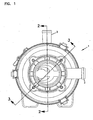
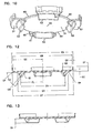
- An example of such a crankcase ventilation (CCV) filter arrangement or assembly is depicted in Figs. 1-3 at 1 .
- crankcase gases typically blow-by gases
- a filtration and separation step occurs in the filter arrangement 1 through outlet 3. Filtered gases leave the arrangement 1 through outlet 3.
- filter arrangement 1 is depicted in cross section.
- Crankcase blow-by gas flow entering arrangement 1 through inlet 2 passes into housing interior region 5.
- the gases, as controlled by regulator valve arrangement 6, enter into interior inlet 7.
- the gases are passed into a serviceable filter cartridge 8.
- serviceable with respect to the filter cartridge 8, is meant to refer to the fact that the cartridge 8 can be removed from, and be replaced in, the filter arrangement 1 periodically.
- the gases are passed through an optional first stage coalescer 9 positioned in serviceable cartridge 8.
- the gases After passage through optional first stage coalescer 9, the gases enter interior region 12 surrounded by (and defined by) a first extension of media 15. The gases pass through the media 15 into annular housing region 18, then outwardly from air filter arrangement 1 through outlet 3.
- regulator valve assembly 6 comprises a diaphragm 6a controlled by a spring 6b, although alternatives are possible.
- the extension of media 15 again, surrounds and defines an open interior 12, and during filtering flow gases pass from interior 12 through the media 15 to annular region 18 surrounding the extension of media 15.
- This type of flow will be referred to herein as an "in-to-out filtering flow” or by variants thereof, in some instances.
- Arrangements that operate in the above-described general manner are known, and are described in US 6,852,148 , incorporated herein by reference.
- a typical filter arrangement 1 includes, in some instances, a bypass valve arrangement (not shown) to accommodate undesirable pressure increases or pulses within the assembly 1.
- liquids are coalesced and separated by media within the cartridge 8, for the example shown, by media 19 within first filter 9 and by passage with in-to-out flow through first media extension 15.
- This liquid can drain, by gravity, to bottom drain 20 and outwardly from the assembly 1.
- a valve arrangement 21 can be provided, to ensure proper operation of the drain 20.
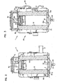
- the filter arrangement 1 includes a housing 25 comprising separable cover 26 and base section 27.
- the cover 26 and base section 27 are secured together by latch arrangement 28.
- Access to service cartridge 8 is obtained by separating the cover 26 from the base 27, when latch arrangement 28 is disconnected. This allows for periodic servicing of the filter assembly 1, by removal of cartridge 8 for refurbishing or replacement.
- a typical service operation involves replacement of cartridge 8, for example at a defined service interval.
- cartridge 8 is sealed by a housing seal within housing 25, to inhibit gas flow to secondary inlet 7 from by passing media within the cartridge 8, in passage toward outlet 3.
- housing seal arrangements are possible, depending on the specific features of the cartridge 8 and the housing 25. An example is described below.
- the cartridge 8 comprises the first extension of media 15 having opposite media ends 15a and 15b.
- the first extension of media 15 has an inner surface 15i an outer surface 15o and, as described, surrounds and defines open interior 12.
- the cartridge includes a first end cap 30.
- End cap 30 is positioned at media end 15a, which, in the example shown, is an upper end of media 15 when cartridge 8 is positioned for ordinary use.
- the end cap 30 is an open end, meaning that it surrounds and defines an aperture 33 in gas flow communication with cartridge interior 12.
- the particular cartridge 8 depicted also includes a second end cap 31 which in use is a lower end cap, positioned at end 15b, of the first extension of media 15.
- the end cap 31 depicted includes features of a media overlap axial drain arrangement defined and discussed below.
- end cap 30 includes a housing seal thereon, for sealing the cartridge 8 against a housing component, to ensure air within region 5 cannot bypass media 15 to reach outlet 3.
- a variety of housing seal arrangements can be used.
- the particular housing seal arrangement 34 depicted is a radial seal arrangement, defining and surrounding aperture 33 and sized and configured to seal against an outer surface of a housing inlet flange 40. This type of radial seal arrangement is known for crankcase ventilation filters, as described in US 6,852,148 incorporated herein by reference.
- An axial seal arrangement could be used.
- An axial seal would typically comprise a gasket surrounding, and spaced from, aperture 33. This seal region or gasket would extend axially outwardly from media 15, to be pressed against housing components, in use, to form a seal.
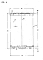
- FIG. 4 in which cartridge 8 is depicted in side elevational view.
- First media extension 15, top end cap 30 and bottom end cap 31 are viewable.
- a top perspective view of cartridge 8 is shown, and end cap 30 is viewable.
- Seal region 34 in the form of a radial seal 34a, defining aperture 33 is viewable.
- radial seal 34a would compress when pushed over (i.e., around) a flow tube 40, in use ( Figs. 2 and 3 ), to provide a housing seal.
- top is used to indicate a portion of a feature described, with respect to its typical orientation during use, relative to other, related portions.
- bottom is oppositely used.
- the arrangement 1 includes a media overlap axial drain arrangement.
- media overlap axial drain arrangement is meant to refer to an arrangement which permits at least some drainage of liquid from media 15 directly out through media bottom end 15b, in overlap with the media 15. That is, media overlap axial drainage is axial drainage for the extension of media 15 that does not require all of the liquid to flow out of a media side surface 15i, 15o, Fig. 8 , to drain.
- Example structure of a media overlap axial drain arrangement is included in end cap 31. (Of course, some liquid can drain out of media surface 15o, in typical applications).
- cartridge 8 is depicted inverted, relative to the view of Fig. 5 .
- second or bottom end cap 31 is viewable.
- a top plan view of cartridge 8 is shown.
- end cap 30 is viewable.
- Fig. 8 a cross-sectional view of cartridge 8 is provided.
- the first extension of media 15 can be seen as surrounding a central region 12 and having opposite ends 15a and 15b, with end 15a being embedded within end cap 30.
- end 15b is partially embedded within end cap 31. This will be understood by reference to Fig. 6 .
- media end 15b is depicted with at least selected portions 50 not embedded within end cap 31.
- other portions of media end 15b are axially covered by (and in the example shown, are embedded within) spaced regions or sections 51 of end cap 31.
- this allows some drainage of liquid directly, axially, outwardly from media 15 through open regions 50.
- directly reference is meant to a drainage that does not require the portion of liquid that undergoes the described axial drainage flow to drain outwardly through one of the media sides, i.e., one of the sides 15i, 15o. Advantages from this are discussed below.
- end cap 31 includes closed central region 32. Central region 32 extends radially across the media open interior 12, at end 15b, closing interior 12 adjacent end 15b to passage of flow from interior 12 through end cap 31, without passage at least partly into the first extension of media 15.
- the example end cap 31 shown has sections 51 that extend from media inner surface 15i to media outer surface 15o, Fig. 8 , i.e., a location outside of the media perimeter. Sections 51 include axial outward projections 53, which operate as cushions to help properly position the cartridge 8 within a housing 25, during use, as shown in Figs. 2 and 3 .
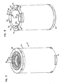
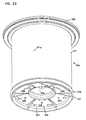
- a bottom perspective view of end cap 31 is viewable, with central closed region 32, and spaced regions 51 for engagement with, and overlap with, portions of bottom end 15b of the first extension of media 15, Figs. 5, 6 and 8 .
- End cap 31 defines spaced, bottom, drain regions 60 therein, between regions 51 which will overlap with portions of the bottom end 15b of media 15, Fig. 8 , to allow at least some drainage axially directly, downwardly, from the media 15 through regions 50, Fig. 6 , during operation.
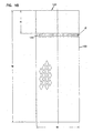
- FIG. 11a bottom plan view of end cap 31 is provided.
- Figs. 12 and 13 selected cross sectional views as defined, are provided.
- cartridge 8 is positioned within a filter arrangement 1, as a crankcase ventilation (CCV) filter. Gases from a crankcase pass into cartridge interior 12 and then through media pack 15, during operation. Within media pack 15 several operations occur. One of these operations is particulate filtering. Another operation is coalescing of liquid entrained within the gases. At least a portion of the coalesced liquid can drain axially directly out of media 15, directly through regions 50, Fig. 6 .
- the drainage is axial it is not meant that the direction is precisely parallel to the central axis 35 of the cartridge 8, but rather that the drainage is directly out of end 15b. It is noted that in operation some additional non-axial drainage may also occur at outside surface 15o, and downwardly between projections 53, to drain 20. This latter would not be “direct, axial” drain flow from end 15b, but would also be found in many example applications of the principles described herein.
- a liquid head (equilibrium level) will build within first extension media 15, above end cap 31, in use. At least a portion of the liquid can drain, for efficient operation, axially, downwardly, directly out of end 15b of the media, due to the media overlap axial drain arrangement, for example through drain openings 60, Fig. 10 , defined by end cap 31. The liquid can then flow to drain 20.
- An advantage results from the media overlap axial drain arrangement.
- liquid can begin to drain from media 15, with lower liquid head, when the media overlap axial drain arrangement is present.
- the relatively high liquid drain rate also helps clear media 15 of entrained material.
- the media used for the first extension media 15 will typically be a fibrous media that fills (except for air pores) the volume between outside surface 15o and inside surface 15i.
- the media 15 defines a generally cylindrical media region, with a generally cylindrical outer surface 15o and a generally cylindrical inner surface 15i, although alternate configurations are possible.
- An example of a manner in which to accomplish such a media definition is through coiling a media wrap around an inner liner. In the alternative, individual, separate, wraps can be made and be positioned overlapping one another
- the media 15 can be described as defining, at end 15b, an end area X.
- the end area X would generally have an area X corresponding to a ring defined by a circle at outer perimeter Y and a circle at inner perimeter Z.
- the area X of course, would be the area of a circle defined by outer perimeter Y minus the area of a circle defined by inner perimeter Z.
- the cartridge end cap 31 typically includes openings 60 corresponding to overlap with at least 20% of the surface area X defined by bottom 15b, usually at least 30% of X, and often at least 40% of X.
- about 50% of the area X defined by bottom end 15b is open to direct axial drain from the media 15, although alternatives are possible.
- end caps 30 and 31 are molded-in-place end caps.
- a material such as polyurethane, for example polyurethane foam, can be used.
- An example polyurethane foam is described herein below in Section II.
- housing bottom 27 includes an internal, circular, shield 80 thereon, projecting upwardly from housing bottom 81, and surrounding and spaced from cartridge 8.
- the shield 80 helps with centering the cartridge 8.
- the shield 80 also helps block liquid flow in region 81 from entering into region 82, i.e., annular region 18.
- the shield 80 will extend an axial length, along the outside of cartridge 8 a length of about 30 mm - 60 mm, although alternatives are possible.
- Some assemblies 1 can be constructed with no shield.
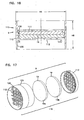
- first stage coalescer 9 Cartridge 8 is configured so that as gases pass into region 12, through end cap 30, they pass through the first stage coalescer 9.
- the first stage coalescer 9 can be generally as described for similar coalescers in US 6,852,148 , incorporated herein by reference. Again, first stage coalescer 9 is optional, and its use, in part, turns upon the level of efficiency desired in accomplishing separation of liquid, as well as the volume available for the assembly 1, within an engine system.
- region 32 can be provided with an upper surface 32a, Figs. 2 and 3 , configured with a raised central portion (not shown) to facilitate liquid flow into media 15.
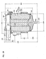
- a media pack 90 comprising first extension of media 15 surrounding optional first stage coalescer 9 is depicted.
- media pack 90 is depicted in cross-section.
- media pack 90 would be assembled, and then the end caps 30, 31, would be molded-in-place.
- first extension of media 15 is positioned surrounding an internal liner 100.
- the internal liner would typically have a porous region 101.
- the optional first stage coalescer 9 is positioned within the media pack 90, adjacent an end which will define media end 15a, in use.
- the first stage coalescer 9 comprises a framework 110 having media 19 positioned therein.
- the framework 110 includes an upper grid 111 and a lower grid 112.
- a subassembly 115 comprising the coalescer filter 9 is viewable.
- the coalescer filter 9 is depicted in exploded view, indicating assembly.
- the coalescer 9 includes a base 120 having lower grid 112 and a sidewall 121.
- Media 19 is positioned within the base 120, surrounded by sidewall 121 and against grid 113.
- Grid 112 can then be snapped in place surrounded by sidewall 121, to form the subassembly 9.
- an interference or snap fit connection between grid 112 and sidewall 121 is shown at 130.
- the media 19 is provided in two pads 19a, 19b, although alternatives are possible.
- the subassembly 115 would be positioned within liner 100.
- the liner 100 is provided with an inner bead or shelf at 130.
- Subassembly 9 can be positioned within region 131 of liner 100, with sidewall 121 positioned on bead or shelf 130, to be secured in place when end cap 30 is molded in place.
- AA 129.4 mm
- AB 3 mm
- AC 203.6 mm
- AD 191 mm
- AE 9.6 mm
- AF 129.4 mm.
- BA 129.4 mm
- BB 3.0 mm
- BC 191 mm
- BD 203.6 mm
- BE 9.6 mm
- BF 129.4 mm.
- CA 18.68 mm
- CB 7.58 mm
- CC 2.5 mm
- CD 2.5 mm.
- DA 124.5 mm
- DB 62.3 mm
- DC 30°
- DD 22°
- DE 45°
- DF 2.3 mm radius
- DG 4.5 mm radius.
- end caps 30, 31 will be molded in place end caps.
- end caps 30, 31 will be molded in place end caps.
- a variety of materials can be used for the end caps, an example being urethane.
- polyurethane foam will be used to provide a relatively soft arrangement convenient for defining radial seal 34 and also for junctions or bumps 53.
- the formula chosen will be such as to provide end caps (parts molded from the polyurethane) having an as molded density of no greater than 28 lbs./cubic foot (about 450 kilograms/cubic meter), more preferably no more than 22 lbs./cubic foot (355 kilograms/cubic meter), typically no greater than 18 lbs/cubic foot (290 kilograms/cubic meter) and usually within the range of 12 to 17 lbs/cubic foot (192-275 kilograms/cubic meter). Lower densities can be used, if the material is formulated such that it can be controlled for proper molding and rise.
- molded density is meant to refer to its normal definition of weight divided by volume.
- a water displacement test or similar test can be utilized to determine volume of a sample of the molded foam. It is not necessary when applying the volume test, to pursue water absorption into the pores of the porous material, and to displace the air the pores represent. Thus, the water volume displacement test used, to determine sample volume, would be an immediate displacement, without waiting for a long period to displace air within the material pores. Alternately stated, only the volume represented by the outer perimeter of the sample need be used for the as molded density calculation.
- compression load deflection is a physical characteristic that indicates firmness, i.e. resistance to compression. In general, it is measured in terms of the amount of pressure required to deflect a given sample of 25% of its thickness. Compression load deflection tests can be conducted in accord with ASTM 3574, incorporated herein by reference. In general, compression load deflection may be evaluated in connection with aged samples. A typical technique is to measure the compression load deflection on samples that have been fully cured for 72 hours at 75°F or forced cured at 190°F for 5 hours.
- Preferred materials will be ones which when molded, show a compression load deflection, in accord with ASTM 3574, on a sample measured after heat aging at 158° F for seven days, on average, of 14 psi or less, typically within the range of 6-14 psi, and often within the range of 7-10 psi.
- Compression set is an evaluation of the extent to which a sample of the material (that is subjected to compression of the defined type and under defined conditions), returns to its previous thickness or height when the compression forces are removed.
- Conditions for evaluating compression set on urethane materials are also provided in ASTM 3574.
- Typical desirable materials will be ones which, upon cure, provide a material that has a compression set of no more than about 18%, and typically about 8-13%, when measured on a sample compressed to 50% of its height and held at that compression at a temperature of 180°F for 22 hours.
- the compression load deflection and compression set characteristics can be measured on sample plugs prepared from the same resin as used to form the end cap, or on sample cut from the end cap.
- industrial processing methods will involve regularly making test sample plugs made from the resin material, rather than direct testing on portions cut from molded end caps.
- Urethane resin systems useable to provide materials having physical properties within the as molded density, compression set and compression load deflection definition as provided above, can be readily obtained from a variety of polyurethane resin formulators, including such suppliers as BASF Corp., Wyandotte MI, 48192.
- One example usable material includes the following polyurethane, processed to an end product having an "as molded" density of 14-22 pounds per cubic foot (224-353 kilograms/cubic meter).
- the polyurethane comprises a material made with I36070R resin and I3050U isocyanate, which are sold exclusively to the assignee Donaldson by BASF Corporation, Wyandotte, Michigan 48192.
- the materials would typically be mixed in a mix ratio of 100 parts I36070R resin to 45.5 parts I3050U isocyanate (by weight).
- the specific gravity of the resin is 1.04 (8.7 lbs/gallon) and for the isocyanate it is 1.20 (10 lbs/gallon).
- the materials are typically mixed with a high dynamic shear mixer.
- the component temperatures should be 70-95°F.
- the mold temperatures should be 115-135°F.
- the resin material I36070R has the following description:
- the I3050U isocyanate description is as follows:
- the material for the optional first stage coalescer media 9 would typically be a fibrous media, such as polyester depth media.
- Preform structural component for the cartridge 8 can comprise plastic or metal components. Typically plastic components will be preferred. For the inner liner expanded metal is typical. For non-media and non-liner components of the first stage filter coalescer filter 9, typically plastic such as carbon filled nylon are used.
- the housing sections are typically molded plastic, for example glass filled nylon.
- a regulator valve arrangement can be made utilizing a flexible diaphragm and coiled metal spring arrangement, from conventional materials.
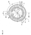
- FIGS. 19-26 Some Alternate Filter Cartridge Configurations, FIGS. 19-26
- FIGS. 19 - 22 A first alternate example is shown in FIGS. 19 - 22 .
- FIG. 19 is a bottom perspective view of a cartridge
- FIG. 20 is a cross-sectional view of a cartridge
- Fig. 21 a bottom plan view.
- Fig. 22 an assembly including the cartridge is depicted.
- crankcase ventilation cartridge 200 is depicted.
- the cartridge 200 is configured to be installed within a crankcase ventilation filter assembly, Fig. 22 , during use.
- the cartridge 200 comprises a media pack 201 and first and second opposite end caps 202 and 203.
- end cap 202 would be an upper end cap
- end cap 203 would be a lower end cap.
- the cartridge 200 is configured for "in-to-out" flow during filtering. That is, media pack 201 surrounds an open central interior 225, FIG. 20 , into which a crankcase ventilation gases are directed. The gas pass outwardly through the media pack 201 to a region surrounding the media, during filtering in use.
- Bottom end cap 203 includes a central region 204 which closes a bottom end of an interior region 225, FIG. 20 .
- End cap 203 also includes an outer rim section 205, in axial overlap with a media pack 201.
- the rim section 205 includes a media overlap axial drain arrangement 210, Fig. 19 .
- the media overlap axial drain arrangement 210 depicted has two windows or drain types: outer rim drain segments 211; and apertures 212.
- the outer rim sections 211 generally comprise spaced drain windows 214 in the end cap 203, which axially overlap an outer, and lower, edge 201x of the media pack, and extend radially inwardly from the outer lower edge 201x a selected distance.
- the distance of media pack overlap inwardly from outer edge 201x will typically be at least 4 % of the radial thickness of the media pack 201, usually at least 7%; and, typically not more than 25%, and usually not more than 20%, of this thickness.
- each drain window 211 The actual dimension of overlap i.e. extension radially inwardly from outer edge 201x, will vary from arrangement to arrangement. However, although alternatives are possible, this dimension will be at least 4 mm, typically 4 mm - 20 mm for each drain window 211.
- the circumferential width of each window 211 shown in FIG 21 at dimension ZE will typically be at least 15 mm and not more than 45 mm, for example 20-40 mm, although alternatives are possible.
- the number of drain windows 211 will typically be at least one, often at least two, usually 2-8, although alternatives are possible.
- Apertures 212 are also positioned in overlap with the media pack 201. However, each aperture 212 is spaced from the media outer edge 201x, and is typically surround by the material of the end cap 203.
- the apertures 212 can have variety of shapes, circular ones being shown. Typical dimensions for the apertures 212 would be for each to have an open area of at least 0.04% and typically at least 0.05% of an area defined by the perimeter of the end cap 203. Typically each aperture 212 comprises 0.04 - 1% of the perimeter area of end cap 203, although alternatives are possible.
- the number of apertures 212 may be varied, for the example shown three (3) apertures 212 are depicted. Typically, the number of apertures 212 will be 2 to 8, inclusive.
- the overlap will be at least 0.5% of this area, not more than 15% of this area, although alternatives are possible.
- each aperture 212 is located at least 10% of a distance across media pack 201 from each of the inner and outer edges (201i; 201x) of the media pack 201, typically at least 20% of this distance.
- end cap 203 includes downwardly projecting projections or bumpers 220, to facilitate secure positioning within housing during use.
- cartridge 200 is depicted in cross section.
- Window 211 can be seen in axial overlap with a bottom end 201b of media pack 201, to permit drainage.
- Drain aperture 212 is shown overlapping a central portion of bottom end 201b of media pack 201.
- media pack 201 can be seen surrounding central open interior 225.
- End cap 202 can be seen as including central aperture 226 therein, to permit inlet flow of air to be filtered. End cap 202 is also depicted as including a seal region 230 thereon for sealing for housing during installation. The particular seal region 230 depicted is configured as an outside radial seal. That is, sealing between the end cap 202 and a housing arrangement in use would generally be by compression of region 230 against an annular housing seal surface. Alternative seal types and locations can be used.
- the particular cartridge 200 depicted in FIG. 20 does not include a first stage filter analogous to filter 9, FIG. 8 herein. However, such an arrangement could be utilized with the principles of FIG. 20 .
- Materials utilized for the media 201 can be analogous to those described herein in further embodiments.
- the material utilized for the end caps 202, 203 comprise a polyurethane material as previously described, if desired.
- the media pack 201 can include an inner and/or outer liner for support, as may be desired in some instances.
- Example liners are indicated in FIG. 20 as inner liner 235 and outer liner 236, respectively.
- the inner liner 235 and outer liner 236 may each comprise, for example, an expanded metal liner, a porous metal liner, or a plastic (porous) liner.
- ZE 30 mm
- ZF 120°
- ZG 114.4 mm diameter
- ZH 4 mm diameter
- ZI 89.6 mm diameter
- ZJ 132.8 mm diameter.
- other dimensions can be determined from scale.
- the cartridge 200 can be said to have a media pack 201 having opposite flow faces, first, outer, outlet flow face 201y; and, second, inner, inlet flow face 201z.
- gas flow generally goes from the inlet flow face 201z to the outlet flow face 201y.
- the media 201 also includes a lower, or downwardly directed in use, edge 201b that operates as a drain edge for liquid within the media pack 201.
- the drain edge 201b extends between the flow faces 201y, 201z.
- the axial overlap drain arrangement 210 at end cap 203 is generally in overlap with edge 201b.
- FIG. 22 cross-sectional view of a crankcase ventilation filter assembly 250 including cartridge 200 therein as a serviceable (i.e., removable replaceable) part is shown.
- housing 260 is depicted having a bottom drain 261 for collected liquid and an upper, access, cover assembly 262.
- a gas flow inlet assembly 263 is provided in the access cover arrangement 262 to direct crankcase ventilation gases into cartridge interior 225.
- the housing 260 includes a base 265 having an air flow outlet 266. Filtered gases can leave housing 260 through outlet 266, after they have passed (with filtering) through media pack 201 in an in-to-out flow.
- the cover assembly 262 is shown latched in place by latches 267.
- the cover assembly 262 can include a regulation valve arrangement 270 therein, to control flow.
- assembly 250 provides for a filtering of crankcase ventilation gases.
- the filter gases leave the assembly 263 through outlet 266.
- Coalesced liquid from the gases drains downwardly through the axial overlap drain arrangement 210 characterized in connection with Figs. 19-21 , and outwardly from housing 260 via bottom drain 261.
- cartridge 300 comprises media pack 301, first, top, end cap 302, and second, bottom, end cap 303.
- Cartridge 300 is configured for out-to-in flow during filtering as discussed below.
- the bottom end cap 303 includes a closed central region 304 (which closes central open region 320, Fig. 24 ) and an outer region 305 (in axial overlap with media pack 301) with a drain media axial overlap arrangement in the form of apertures 306 therein. End cap 303 also includes an outer rim 307 with o-ring 308 positioned thereon as a housing seal. Further, downward directed vanes 311 are positioned in overlap with region 305. The vanes 311 are positioned between the apertures 306.
- the media pack 301 surrounds central open region 320 and inner liner 321.
- the central open region 320 is closed at lower end 320x by central region 304.
- End cap 302 comprises end piece 330 and outer housing seal member 331.
- the end piece 330 for the example shown, is integral with inner liner 321.
- Still referring to FIG. 22 for the example shown end cap 303 is also integral with center liner 320.
- end piece 330, end cap 303 and inner liner 321 comprise integral, molded, piece 332, for example, of a plastic.
- the piece 332 comprises end piece 330, end cap 303, and liner 321 will sometimes be referenced herein as a piece or spool 332 around which media pack 301 is positioned.
- Seal member 331 is secured to the end piece 330.
- the housing seal member 331 can be adhered in place, or be molded in place.
- the seal member 331 is an axial pinch seal configured for engagement between selected housing components, during use.
- upper end cap 302 includes a central aperture 335 oriented for air flow of crankcase ventilation gases after filtering from internal region 320; the cartridge 300 being configured for "out-to-in" flow during filtering.
- the gases are directed through the media pack 301 from outside end, and once filtered enter central region 320 by passage through apertures and inner liner 321.
- the filtered gases can then escape through aperture 335 and be directed where desired by the assembly.
- coalescing of liquid will occur, with drainage axially downwardly, through axial overlap drain arrangement comprising the apertures 306, Fig. 23 .
- Seal ring 308 can provide for sealing engagement with housing appropriately sized and configured to receive cartridge 300.
- the media pack 301 may generally comprise material analogous to those described herein for other applications.
- the plastic selected for piece 340 would generally be as appropriate with the structural rigidity and chemical resistance, for the application of use.
- a useable example for some application is nylon, for example glass fiber reinforced nylon 66.
- Seal member 331 can comprise a variety of materials selected for the particular application involved. Typically seal material 331 will comprise a materials sufficiently resilient, for the use intended.
- the seal member 331 can be configured for a variety of types of sealing. Seal member 331 can be specifically configured to form an outwardly directed seal when inserted in a housing. It can also be specifically configured to be pinched as an axial pinch seal between housing members when installed.
- each aperture 306 will be at least two and not more than 10.
- Each aperture will typically be positioned at least 10% of the thickness of the media pack 301 from inner region 301i, and 10% of the thickness of the media pack 301 from outer edge 301o.
- each aperture 306 is positioned in axial overlap with a region of media pack 301 spaced at least 20% of the thickness of the media pack 301 from each of the inner and outer edges 301i and 301o.
- the shape of the apertures 306 is a matter of choice, circular apertures being convenient.
- central region 304 is raised above a bottom of end cap 303 by about 15 mm (usually at least 10 mm), and is dome shaped with a central higher portion. This helps liquid in interior 320 to drain back into the media 301 and downwardly through the axial overlap drain arrangement defined by apertures 306.
- the axial overlap drain arrangement also includes windows 340 along an inner region of end cap 303, in axial overlap with the media pack 301 along an inner edge 3010, Fig. 24 , thereof.
- the windows 340 further provide for a drain of liquid collected in media pack 301, during use.
- Windows 340 may be generally characterized previously for windows 211, except located adjacent an interior edge of the media pack 301. Typically the overlap amount in terms of thickness of the media pack 301 is at least 4%, typically at least 7%, usually not more than 25% and typically not more than 20%.
- the total area of overlap of the axial drain arrangement (comprising the apertures 306 plus the windows 340), in terms of the overall area of the bottom end 301b, Fig. 24 , of the media pack 301, is at least 0.5% and typically more than 15, although alternatives are possible.
- the cartridge 300 includes a media pack 301 having a first, outer, inlet flow face 301y; and, a second, inner, outlet flow face 301z.
- gases flow from the inlet flow face 301y to the outlet flow face 301z.
- the media pack 301 also includes a lower, drain, edge or end 301b, extending between the faces 301y, 301z.
- liquid coalescing within the media pack 301 can drain downwardly and outwardly through the end 301b.
- the axial overlap drain arrangement as a portion of the end cap 303 that is open, and overlap with end 301b.
- the cartridge 300 includes a housing seal arrangement including two housing seals thereon, pinch seal 331 and outwardly directed o-ring or radial seal 308, on opposite end caps 302, 303 respectively.
- FIG. 26 cross-sectional view of a crankcase ventilation filter assembly 359 including cartridge 300 therein as removable and replaceable (i.e., serviceable) component within a housing 360.
- the housing 360 includes a base 361 and cover assembly 362.
- a gas flow inlet is indicated in the base 361, at 365.
- the cartridge 300 is configured for out-to-in flow during filtering. Gas passes into the filter assembly 360 through inlet 365 and into interior annulus 370. The gas then passes through the media pack 301 into interior 326. It can then pass into cover assembly 362 and out from the housing 360 through outlet 373.
- the cartridge 300 in shown sealed to the housing base 361 by lower housing seal member 308 and between the cover assembly 362 and base 361 by housing seal member 331.
- drain 380 In the bottom of assembly 359 is provided drain 380.
- the extension of media 15 will comprise a continuous fibrous body formed.
- a typical shape would be cylindrical, although alternatives are possible.
- a gradient can be provided in a media stage, by first applying one or more layers of wet laid media of first type and then applying one or more layers of a media (typically a wet laid media) of a different, second, type.
- a media typically a wet laid media
- the gradient involves use of two or more media types which are selected for differences in efficiency. This is discussed further below.
- wet laid sheet “media sheet” or variants thereof, is used to refer to the sheet material that is used to form the media extension 15 of a filter, as opposed to the overall definition of the total media extension 15 in the filter. This will be apparent from certain of the following descriptions.
- Media extensions 15 of the type of primary concern herein, are at least used for coalescing/drainage, although they typically also have particulate removal function and may comprise a portion of an overall media stage that provides for both coalescing/drainage and desired removal efficiency of solid particulate removal.
- first stage coalescer 9 and a media extension 15 were described in the depicted arrangements. Wet laid media according to the present descriptions can be utilized in either stage. However typically the described media would be utilized in extension 15 i.e., the media which forms, in the arrangements shown, a tubular media stage 15.
- an example media composition used to form a media extension 15 in a CCV (crankcase ventilation) filter for coalescing/drainage is typically as follows:
- Media in accord with the general definitions provided herein, including a mix of bi-component fiber and other fiber, can be used as any media stage in a crankcase ventilation filter as generally described above in connection with the figures.
- a tubular stage i.e., extension 15.
- it When used in this manner, it will typically be wrapped around a center core of the filter structure, in multiple layers, for example often at least 20 layers, and typically 20-70 layers, although alternatives are possible.
- the total depth of the wrapping will be about 0.25 - 2 inches (6 - 51 mm), usually 0.5 - 1.5 (12.7 - 38.1 mm) inches depending on the overall efficiency desired. The overall efficiency can be calculated based upon the number of layers and the efficiency of each layer.
- the efficiency at 10.5 feet per minute (3.2 m/min) for 0.3 micron DOPE particles for media stage comprising two layers of wet laid media each having an efficiency of 12% would be 22.6%, i.e., 12% + .12 x 88.
- final media stage refers to a stage resulting from wraps or coils of the sheet(s) of the media.
- the media extension performs two important functions:
- a calculated pore size for media used to form media extension 15 within the range of 12 to 50 micron is generally useful. Typically the pore size is within the range of 15 to 45 micron.
- the portion of the media which first receives gas flow with entrained liquid for designs characterized in the drawings the portion adjacent the inner surface of tubular media construction, through a depth of at least 0.25 inch (6.4 mm), has an average pore size of at least 20 microns. This is because in this region, a larger first percentage of the coalescing/drainage will occur. In outer layers, in which less coalescing drainage occurs, a smaller pore size for more efficient filtering of solid particles, may be desirable in some instances.
- X-Y pore size and variants thereof when used herein, is meant to refer to the theoretical distance between fibers in a filtration media.
- X-Y refers to the surface direction versus the Z direction which is the media thickness. The calculation assumes that all the fibers in the media are lined parallel to the surface of the media, equally spaced, and ordered as a square when viewed in cross-section perpendicular to the length of the fibers.
- the X-Y pore size is a distance between the fiber surfaces on the opposite corners of the square. If the media is composed of fibers of various diameters, the d 2 mean of the fiber is used as the diameter. The d 2 mean is the square root of the average of the diameters squared.
- an average pore size of about 30-50 microns will be useful.
- Solidity is the volume fraction of media occupied by the fibers. It is the ratio of the fibers volume per unit mass divided by the media's volume per unit mass.
- Typical materials preferred for use in media extension 15 according to the present disclosure have a percent solidity at 0.125 psi (8.6 ) of fewer than 10%, and typically fewer than 8%, for example 6-7%.
- the thickness of media utilized to make media extension 15 according to the present disclosure is typically measured using a dial comparator such as an Ames #3W (BOCA Melrose MA) equipped with a round pressure foot, one square inch. A total of 2 ounces (56.7 g) of weight is applied across the pressure foot.
- a dial comparator such as an Ames #3W (BOCA Melrose MA) equipped with a round pressure foot, one square inch. A total of 2 ounces (56.7 g) of weight is applied across the pressure foot.
- Typical media sheets useable to be wrapped or stacked to form media arrangements according to the present disclosure have a thickness of at least 0.01 inches (0.25 mm) at 0.125 psi (8.6 ), up to about 0.06 inches (1.53 mm), again at 0.125 psi (8.6 ). Usually, the thickness will be 0.018 - 0.03 inch (0.44 - 0.76 mm) under similar conditions.
- Compressibility is a comparison of two thickness measurements made using the dial comparator, with compressibility being the relative loss of thickness from a 2 ounce (56.7 g) to a 9 ounce (255.2 g) total weight (0.125 psi - 0.563 psi or 8.6 samples - 38.8 worth).
- Typical media at about 40 lbs/3,000 square feet (18 kg/278.7 sq. m) basis weight) useable in wrappings according to the present disclosure, exhibit a compressibility (percent change from 0.125 psi to 0.563 psi or 8.6 - 38.8 ) of no greater than 20%, and typically 12-16%.
- the preferred efficiency stated is desirable for layers or sheets of media to be used to generate crankcase ventilation filters. This requirement indicates that a number of layers of the wet laid media will typically be required, in order to generate an overall desirable efficiency for the media stage of typically at least 85% or often 90% or greater, in some instances 95% or greater.
- DOPE efficiency is a fractional efficiency of a 0.3 micron DOPE particle (dactyl phthalate) challenging the media at 10 fpm.
- a TSAR model 3160 Bench (TSAR Incorporated, St. Paul, Minnesota) can be used to evaluate this property. Model dispersed particles of DOPE are sized and neutralized prior to challenging the media.
- Typical (wet laid) air filtration media accomplishes strength through utilization of added binders. However this comprises the efficiency and permeability, and increases solidity.
- the media sheets and stages according to preferred definitions herein typically include no added binders, or if binder is present it is at a level of no greater than 7% of total fiber weight, typically no greater than 3% of total fiber weight.
- Machine direction tensile is the breaking strength of a thin strip of media evaluated in the machine direction (MD). Reference is to Tapir 494. Machine direction tensile after fold is conducted after folding a sample 180° relative to the machine direction. Tensile is a function of test conditions as follows: sample width, 1 inch (25.4 mm); sample length, 4 inch gap (101.6 mm); fold -1 inch (25.4 mm) wide sample 180° over a 0.125 inch (3.2 mm) diameter rod, remove the rod and place a 10 1b. weight (4.54 kg) on the sample for 5 minutes. Evaluate tensile; pull rate - 2 inches/minute (50.8 mm/minute).
- the fiber composition of the media include 30 to 70%, by weight, of bi-component fiber material.
- a major advantage of using bi-component fibers in the media is effective utilization of fiber size while maintaining a relatively low solidity. With the bi-component fibers, this can be achieved while still accomplishing a sufficiently high strength media for handling installation in crankcase ventilation filters.
- the bi-component fibers generally comprise two polymeric components formed together, as the fiber.
- Various combinations of polymers for the bi-component fiber may be useful, but it is important that the first polymer component melt at a temperature lower than the melting temperature of the second polymer component and typically below 205°C.
- the bi-component fibers are integrally mixed and evenly dispersed with the other fibers, in forming the wet laid media. Melting of the first polymer component of the bi-component fiber is necessary to allow the bi-component fibers to form a tacky skeletal structure, which upon cooling, captures and binds many of the other fibers, as well as other bi-component fibers.
- the bi-component fibers will be formed in a sheath core form, with a sheath comprising the lower melting point polymer and the core forming the higher melting point.
- the low melting point e.g., about 80 to 205°C
- thermoplastic is typically extruded around a fiber of the higher melting point material (e.g., about 120 to 260°C).
- the bi-component fibers typically have a average largest cross-sectional dimension (average fiber diameter if round) of about 5 to 50 micrometer often about 10 to 20 micrometer and typically in a fiber form generally have an average length of at least 1 mm, and not greater than 30 mm, usually no more than 20 mm, typically 1-10 mm.
- largest in this context, reference is meant to the thickest cross-section dimension of the fibers.
- Such fibers can be made from a variety of thermoplastic materials including polyolefin's (such as polyethylene's, polypropylenes), polyesters (such as polyethylene terephthalate, polybutylene terephthalate, PCT), nylons including nylon 6, nylon 6,6, nylon 6,12, etc.
- polyolefin's such as polyethylene's, polypropylenes
- polyesters such as polyethylene terephthalate, polybutylene terephthalate, PCT
- nylons including nylon 6, nylon 6,6, nylon 6,12, etc.
- Any thermoplastic that can have an appropriate melting point can be used in the low melting component of the bi-component fiber while higher melting polymers can be used in the higher melting "core” portion of the fiber.
- the cross-sectional structure of such fibers can be a "side-by-side” or "sheath-core” structure or other structures that provide the same thermal bonding function.
- lobed fibers where the tips have lower melting point polymer.
- the value of the bi-component fiber is that the relatively low molecular weight resin can melt under sheet, media, or filter forming conditions to act to bind the bi-component fiber, and other fibers present in the sheet, media, or filter making material into a mechanically stable sheet, media, or filter.
- the polymers of the bi-component (core/shell or sheath and side-by- side) fibers are made up of different thermoplastic materials, such as for example, polyolefin/polyester (sheath/core) bi-component fibers whereby the polyolefin, e.g. polyethylene sheath, melts at a temperature lower than the core, e.g. polyester.
- Typical thermoplastic polymers include polyolefins, e.g. polyethylene, polypropylene, polybutylene, and copolymers thereof, polytetrafluoroethylene, polyesters, e.g.
- polyethylene terephthalate polyvinyl acetate, polyvinyl chloride acetate, polyvinyl butyral, acrylic resins, e.g. polyacrylate, and polymethylacrylate, polymethylmethacrylate, polyamides, namely nylon, polyvinyl chloride, polyvinylidene chloride, polystyrene, polyvinyl alcohol, polyurethanes, cellulosic resins, namely cellulosic nitrate, cellulosic acetate, cellulosic acetate butyrate, ethyl cellulose, etc., copolymers of any of the above materials, e.g.
- ethylene-vinyl acetate copolymers ethylene-acrylic acid copolymers, styrene-butadiene block copolymers, Kraton rubbers and the like.
- Particularly preferred in the present invention is a bi-component fiber known as 271P available from DuPont. Others fibers include FIT 201, Kuraray N720 and the Nichimen 4080 and similar materials. All of these demonstrate the characteristics of cross-linking the sheath polymer upon completion of first melt. This is important for liquid applications where the application temperature is typically above the sheath melt temperature. If the sheath does not fully crystallize then the sheath polymer will remelt in application and coat or damage downstream equipment and components.
- An example of a useable bi-component fiber for forming wet laid media sheets for use in CCV media is Dupont polyester bi-component 271P, typically cut to a length of about 6 mm.
- the bi-component fibers provide a.matrix for the crankcase ventilation filter media.
- the additional fibers or secondary fibers sufficiently fill the matrix to provide the desirable properties for coalescing and efficiency.
- the secondary fibers can be polymeric fibers, glass fibers, metal fibers, ceramic fibers or a mixture of any of these. Typically glass fibers, polymeric fibers or a mixture are used.
- Glass fibers useable in filter media of the present invention include glass types known by the designations: A, C, D, E, Zero Boron E, ECR, AR, R, S, S-2, N, and the like, and generally, any glass that can be made into fibers either by drawing processes used for making reinforcement fibers or spinning processes used for making thermal insulation fibers.
- Non-woven media of the invention can contain secondary fibers made from a number of both hydrophilic, hydrophobic, oleophilic, and oleophobic fibers. These fibers cooperate with the glass fiber and the bi-component fiber to form a mechanically stable, but strong, permeable filtration media that can withstand the mechanical stress of the passage of fluid materials and can maintain the loading of particulate during use.
- Secondary fibers are typically monocomponent fibers with average largest cross-sectional dimension (diameters if round) that can range from about 0.1 on up, typically 1 micron or greater, often 8-15 microns and can be made from a variety of materials including naturally occurring cotton, linen, wool, various cellulosic and proteinaceous natural fibers, synthetic fibers including rayon, acrylic, aramide, nylon, polyolefin, polyester fibers.
- One type of secondary fiber is a binder fiber that cooperates with other components to bind the materials into a sheet.
- Another type of secondary fiber is a structural fiber that cooperates with other components to increase the tensile and burst strength the materials in dry and wet conditions.
- the binder fiber can include fibers made from such polymers as polyvinyl chloride, polyvinyl alcohol. Secondary fibers can also include inorganic fibers such as carbon/graphite fiber, metal fiber, ceramic fiber and combinations thereof.
- the secondary thermoplastic fibers include, but are not limited to, polyester fibers, polyamide fibers, polypropylene fibers, copolyetherester fibers, polyethylene terephthalate fibers, polybutylene terephthalate fibers, polyetherketoneketone (PEKK) fibers, polyetheretherketone (PEEK) fibers, liquid crystalline polymer (LCP) fibers, and mixtures thereof.
- Polyamide fibers include, but are not limited to, nylon 6, 66, 11, 12, 612, and high temperature "nylons" (such as nylon 46) including cellulosic fibers, polyvinyl acetate, polyvinyl alcohol fibers (including various hydrolysis of polyvinyl alcohol such as 88% hydrolyzed, 95% hydrolyzed, 98% hydrolyzed and 99.5% hydrolyzed polymers), cotton, viscose rayon, thermoplastic such as polyester, polypropylene, polyethylene, etc., polyvinyl acetate, polylactic acid, and other common fiber types.
- nylon 6 66, 11, 12, 612 and high temperature "nylons” (such as nylon 46) including cellulosic fibers, polyvinyl acetate, polyvinyl alcohol fibers (including various hydrolysis of polyvinyl alcohol such as 88% hydrolyzed, 95% hydrolyzed, 98% hydrolyzed and 99.5% hydrolyzed polymers), cotton, viscose rayon, thermoplastic such as polyester,
- Mixtures of the fibers can be used, to obtain certain desired efficiencies and other parameters.
- the sheet media of the invention are typically made using papermaking processes. Such wet laid processes are particularly useful and many of the fiber components are designed for aqueous dispersion processing. However, the media of the invention can be made by air laid processes that use similar components adapted for air laid processing.
- the machines used in wet laid sheet making include hand laid sheet equipment, Fourdrinier papermaking machines, cylindrical papermaking machines, inclined papermaking machines, combination papermaking machines and other machines that can take a properly mixed paper, form a layer or layers of the furnish components, remove the fluid aqueous components to form a wet sheet.
- a fiber slurry containing the materials are typically mixed to form a relatively uniform fiber slurry. The fiber slurry is then subjected to a wet laid papermaking process.
- the binder in the bi-component fibers is activated by passing the matt through a heating step.
- the resulting material can then be collected in a large roll if desired.
- Modification of the surface characters of the fibers can enhance drainage capability of filtration media and thus the formed elements of the filter (with respect to pressure drop and mass efficiency).
- a method of modifying the surface of the fibers is to apply a surface treatment such as a flourochemical or silicone containing material, typically up to 5% by weight of the media.
- the surface treatment agent can be applied during manufacture of the fibers, during manufacture of the media or after manufacture of the media posttreatment, or after provision of the media pack.
- Numerous treatment materials are available such as flourochemicals or silicone containing chemicals that increase contact angle: An example is the DuPont Zonyl TM flourochemicals, such as #7040 or #8195.
- Example A is a sheet material useable for example, as a media phase in a crankcase ventilation filter, in which the media phase is required to provide for both good coalescing/drainage and also which can be used in layers to provide useable efficiencies of overall filtration.
- the material will drain well and effectively, for example when used as a tubular media construction having a height of 4 inches - 12 inches (100 - 300.5 mm).
- the media can be provided in multiple wrappings, to generate such a media pack.
- Media example A comprises a wet laid sheet made from a fiber mix as follows: 50% by wt. DuPont polyester bi-component 271P cut to 6 mm length; 40% by wt. DuPont polyester 205 WSD, cut to 6 mm length; and 10% by wt. Owens Corning DS-9501-11 W Advantex glass fibers, cut to 6 mm.
- the DuPont 271P bi-component fiber has an average fiber diameter of about 14 microns.
- the DuPont polyester 205 WSD fiber has an average fiber diameter of about 12.4 microns.
- the Owens Corning DS-9501-11W has an average fiber diameter of about 11 microns.
- the example A material was made to a basis weight of about 40.4 lbs./3,000 sq.ft.
- the material had a thickness at 0.125 psi, of 0.027 inches and at 0.563 psi of 0.023 inches.
- the total percent change (compressibility) from 0.125 to 0.563 psi was only 14%.
- the thickness of the material was 0.021 inches.
- the MD fold tensile was 2.6 lbs./inch width.
- the calculated pore size, X-Y direction, was 43 microns.
- the DOP efficiency of 10.5 feet per minute per 0.43 micron particles, was 6%.
- Example B was made from a fiber mixture comprising 50% by weight DuPont polyester bi-component 271P cut to 6 mm length; and 50% by weight Lausch B 50R microfiber glass.
- the microfiber glass had lengths on the order of about 3-6 mm.
- the DuPont polyester bi-component 271P had an average diameter of 14 microns.
- the Lausch B 50R had an average diameter of 1.6 microns and a d 2 mean of 2.6 microns.
- the sample was made to a basis weight of 38.3 lbs./3,000 square feet.
- the thickness of the media at 0.125 psi, 0.020 inches and at 0.563 psi was 0.017 inches.
- the percent changed from 0.125 psi to 0.563 psi was 15%, i.e., 15% compressibility.
- the sample had a thickness of 0.016 inches.
- the solidity of the material measured at 0.125 psi was 6.9%.
- the permeability of the material was about 204 feet/minute.
- the machine direction fold tensile was measured at 3.9 lbs/inch width.
- the calculated pore size X-Y direction was 18 microns.
- the Exhibit B material would be effective when used as a layer or a plurality of layers to polish filtering. Because of its higher efficiency, it can be used alone or in multiple layers to generate high efficiency in the media.
- This material would be border line as a coalescer/drain material, however, due to the relatively small pore size.
- Exhibit A material could be used to form an inside of the tube, with Exhibit B material used to form an outside of the tube, the two together comprising a filtered media stage in a crankcase ventilation filter of desirable drain properties and overall efficiency of filtering.
- the preferred wet laid media as characterized above can be utilized in a variety of manners in crankcase ventilation filter arrangements. In the arrangements described in the figures, they can be used for the tubular stage, for example. Such media can also be used in the optional first stage, if desired.
- tubular stage will be made using 20-70 wraps of coiled wet laid media in accord with descriptions above. Of course alternatives are possible.
- the tubular media stage comprises a media of the type characterized herein.
- Such media can provide for initially efficient and effective coalescing and drainage, to be useable both as part of the particulate filter stage and as the coalescing/drain stage.
- the media characterized herein can offer a variety of alternate configurations for crankcase ventilation filters.
- An example would be one in which the media is arranged in a tubular form, for flow therethrough a crankcase ventilation gases.
- the media could be configured in panel arrangements or other arrangements.
- a filtration system which manages both coalescing/drainage of our entrained liquid particulates, and also filtration of particles, should be designed to drain the collected liquids rapidly, otherwise functional life of the filter media would be uneconomically short.
- the media is positioned so the liquid can drain from the media rapidly.
- Some key performance properties are: initial and equilibrium fractional efficiency, pressure drop and drainage ability.
- Some key physical properties of the media are thickness, solidity and strength.
- the media for coalescing/drainage is aligned in a manner that enhances the filters capability to drain.
- this would be a media position with the central axis of the tube extending vertically.
- any given media composition will exhibit an equilibrium load height which is a function of the X-Y pore size, fiber orientation and the interaction of the liquid with the fiber surface, measured as contact angle. Collection of liquid in the media will increase in height to a point balanced with the drainage rate of the liquid from the media.
- any portion of the media that is plugged with draining liquid would not be available for filtration.
- portions of the media would increase pressure drop and decrease efficiency across the filter.
- the media factors effecting drainage rate are X-Y pore size, fiber orientation and interaction of the liquid being drained with the fiber surface. Reducing these to accomplish a desirable liquid flow is in part the issue.
- the X-Y pore size being increased, facilitates drainage as explained above. However this reduces the number of fibers for filtration, thus the overall efficiency of the filter.
- relatively thick media pack structure would be made, by using multiple layers of material having a desirable X-Y pore size.
- the fibers would preferably be oriented with a vertical direction of the media if possible, but this approach is generally difficult to maximize.
- the media, if provided in a tubular form would be oriented with the X-Y plane from the wet laid manufacturing process, defining the surface of the tube and with the Z direction being the thickness.
- crankcase ventilation filter cartridge and techniques useable therein are provided.
- an extension of media is provided in a form that allows for direct axial drain downwardly at an end of the media, in use.
- the media is secured within a cartridge, in a manner that allows for the direct axial drain of liquid from the media. This allows drainage with relatively less required accumulation of liquid within the media.
- the principles can be applied in a wide variety of filter cartridge sizes and shapes.
- the techniques involve providing a lower drain end to the media pack, that allows for direct axial drainage from the media during operation.
- the techniques are depicted implemented in a filter cartridge of general style described and depicted in US 6,852,148 .
- the techniques can be applied in all cartridges of alternate configurations.
- a crankcase ventilation filter cartridge in an example shown, includes a first extension of media surrounding a media open interior and having a media first end and a media second end.
- a first end cap is positioned at the media first end.
- the first end cap defines a flow aperture therethrough in communication with the media open interior.
- a housing seal arrangement is provided on the cartridge, to seal the cartridge to a housing structural member in use.
- the media will have media overlap axial drain arrangement positioned at the second end of the first extension of media. The media overlap axial drain arrangement allows for a direct drainage of liquid collected within the media outwardly from the second end of the media. This allows drainage to begin earlier during typical operation.
- the housing seal arrangement is an integrally molded portion of the first end cap and the housing seal arrangement is a radially directed seal, in one instance surrounding and defining the flow aperture.
- the housing seal arrangement is an axial seal.
- the media overlap axial drain arrangement comprises a second end cap positioned at the media second end and having a central closed section extending across the media open interior. In this manner, the second end cap closes the media open interior at the media second end.
- the typical second end cap defines spaced drain regions in direct axial overlap with the media second end.
- direct axial overlap in this context, it is meant that some drainage outwardly from the media second end occurs axially, without required passage outwardly from the outer face of the media.
- the second end cap comprises spaced extensions that extend from the central closed section of the second end cap across the media second end to a location outside of the media outer perimeter.
- the second end cap comprises at least two such spaced extensions, typically 3-6 such spaced extensions, although alternatives are possible.
- the second end cap includes four spaced extensions.
- the spaced extensions each include an axially outwardly directed projection arrangement thereon.
- both the first end cap and second end cap are molded-in-place.
- each is molded from polyurethane foam. (An alternate to this is described.)
- a filter cartridge is provided with a first stage coalescer filter, as an option, positioned surrounded by the first extension of media and extending radially across the media open interior.
- the first stage coalescer filter is positioned then such that flow into the open interior of the filter media, through the first end cap, passes through the first stage coalescer.
- the first stage coalescer filter comprises a region of fibrous media positioned between an upstream grid and a downstream grid.
- the first extension of media defines a cylindrical media extension having an outer surface and an inner surface.
- the first extension of media comprises a fibrous wrap of media coiled around an inner support.
- a useable media is described herein, with respect to selected properties and components.
- crankcase ventilation filtration assembly which includes a housing defining an interior and including a gas flow inlet arrangement, a gas flow outlet arrangement and a liquid drain outlet arrangement.
- a serviceable crankcase ventilation filter cartridge for example according to descriptions herein, is positioned within the housing interior such that during operation normal flow to the housing through the gas flow inlet arrangement is directed through the first extension of media with at least a portion of the coalesced liquid from the first extension of media draining axially therefrom through an axial drain arrangement at a second or lower end of the first extension of media to the liquid drain outlet arrangement of the housing; and, with gas flow from the extension of media directed out of the gas flow outlet arrangement.
- a variety of example features for a housing and serviceable filter cartridge are described.
Claims (24)
- Filtereinsatz (8) einer Kurbelgehäuseentlüftung umfassend:(a) ein Medienpaket (15),(i) welches erste und zweite Enden (15a, 15b) aufweist, wobei die Enden in Verwendung die oberen und unteren Enden des Medienpakets repräsentieren, zwischen denen ein zu filternder Luftstrom in das Medienpaket eintritt;(b) eine Gehäusedichtanordnung (34) zum Dichten des Einsatzes gegen ein Gehäuse;(c) ein Abdeckglied (31), welches das untere Ende des Medienpakets überlappt; und(d) Mittel, die in Verwendung ausgerichtet sind, um zu ermöglichen, dass in dem Luftstrom mitgeführte Flüssigkeit im Wesentlichen vertikal von dem Einsatz hinab fällt,
wobei der Einsatz gekennzeichnet ist durch(e) Öffnungen (60) innerhalb des Abdeckglieds, die ermöglichen, dass in dem Luftstrom mitgeführte Flüssigkeit generell vertikal von dem Medienpaket hinab fällt. - Filtereinsatz einer Kurbelgehäuseentlüftung nach Anspruch 1, wobei:(a) das Medienpaket ein offenes Medien-Inneres umgibt.
- Filtereinsatz einer Kurbelgehäuseentlüftung nach Anspruch 2 beinhaltend:(a) eine erste Endkappe an dem ersten Ende der Medien, welche eine Fluchtende dadurch in Kommunikation mit dem offenen Medien-Innereren definiert.
- Filtereinsatz einer Kurbelgehäuseentlüftung nach Anspruch 3, wobei:(a) die Gehäusedichtanordnung einen integral geformten Anteil der ersten Endkappe beinhaltet.
- Filtereinsatz einer Kurbelgehäuseentlüftung nach einem der Ansprüche 1 bis 4, wobei:(a) die Gehäusedichtanordnung eine radial gerichtete Dichtung aufweist.
- Filtereinsatz einer Kurbelgehäuseentlüftung nach einem der Ansprüche 1 bis 4, wobei:(a) die Gehäusedichtanordnung einen axialen Quetschdichtflansch beinhaltet, welcher auf der ersten Endkappe positioniert ist.
- Filtereinsatz einer Kurbelgehäuseentlüftung nach einem der Ansprüche 1 bis 6, wobei:(a) das Abdeckglied eine zweite Endkappe umfasst, die an dem zweiten Ende der Medien positioniert ist und einen zentralen geschlossenen Abschnitt aufweist, welcher sich über das offene Medien-Innere erstreckt.
- Filtereinsatz einer Kurbelgehäuseentlüftung nach Anspruch 7, wobei:(a) die zweite Endkappe eine Vielzahl von beabstandeten Abflussbereichen in direktem axialen Überlapp mit dem zweiten Ende der Medien definiert.
- Anordnung einer Kurbelgehäuseentlüftung nach Anspruch 8, wobei:(a) die zweite Endkappe ein Gehäusedichtglied darauf beinhaltet.
- Filtereinsatz einer Kurbelgehäuseentlüftung nach Anspruch 8, wobei:(a) die Vielzahl von beabstandeten Abflussbereichen beabstandete Blenden beinhalten, die durch Material der zweiten Endkappe umgeben sind.
- Filtereinsatz einer Kurbelgehäuseentlüftung nach einem der Ansprüche 8 oder 10, wobei:(a) die Vielzahl von beabstandeten Abflussbereichen beabstandete Fenster in Überlapp mit wenigstens einer inneren Kante oder einer äußeren Kante des Medienpakets beinhaltet.
- Filtereinsatz einer Kurbelgehäuseentlüftung nach Anspruch 11, wobei:(a) die Vielzahl von beabstandeten Abflussbereichen Erstreckungen beinhalten, welche sich von einem zentralen geschlossenen Abschnitt der zweiten Endkappe über das zweite Ende der Medien zu einem Ort außerhalb eines äußeren Umfangs der Medien erstrecken.
- Filtereinsatz einer Kurbelgehäuseentlüftung nach Anspruch 11, wobei:(a) die zweite Endkappe wenigstens drei beabstandete Fenster umfasst.
- Filtereinsatz einer Kurbelgehäuseentlüftung nach Anspruch 12, wobei:(a) jede der beabstandeten Verlängerungen eine axiale, nach außen gerichtete Vorsprungsanordnung darauf beinhaltet.
- Filtereinsatz einer Kurbelgehäuseentlüftung nach Anspruch 7, wobei:(a) die erste Endkappe eine an Ort und Stelle geformte Endkappe ist; und(b) die zweite Endkappe eine an Ort und Stelle geformte Endkappe ist.
- Filtereinsatz einer Kurbelgehäuseentlüftung nach Anspruch 15, wobei:(a) die ersten und zweiten Endkappen jeweils Polyurethanschaum sind.
- Filtereinsatz einer Kurbelgehäuseentlüftung nach Anspruch 3 beinhaltend:(a) einen Koaleszenzfilter erster Stufe, welcher umgeben von dem Medienpaket positioniert ist und sich radial über das offene Medien-Innere erstreckt.
- Filtereinsatz einer Kurbelgehäuseentlüftung nach Anspruch 17, wobei:(a) der Koaleszenzfilter erster Stufe einen Bereich faseriger Medien umfasst, die zwischen einem stromaufwärtigen Gitter und einem stromabwärtigen Gitter positioniert sind; und(b) der Koaleszenzfilter erster Stufe derart positioniert ist, dass ein Fluss durch die Flussblende der ersten Endkappe in das offene Medien-Innere durch den Koaleszenzfilter erster Stufe passieren muss, bevor er in das Medienpaket, welches ein offenes Medien-Inneres umgibt, passiert.
- Filter einer Kurbelgehäuseentlüftung nach Anspruch 18, wobei:(a) das Medienpaket um eine innere Auskleidung positioniert ist, welche einen nach innen gerichteten Wulst aufweist; und(b) der Koaleszenzfilter erster Stufe eine auf dem Wulst positionierte äußere Seitenwandung beinhaltet.
- Filtereinsatz einer Kurbelgehäuseentlüftung nach einem der Ansprüche 1 bis 19, wobei:(a) das Medienpaket eine zylindrische Medienverlängerung definiert, welche eine äußere Fläche und eine innere Fläche aufweist.
- Filtereinsatz einer Kurbelgehäuseentlüftung nach einem der Ansprüche 1 bis 20, wobei:(a) das Medienpaket eine faserige Hülle von Medien umfasst, die um ein inneres Mediengestell gewickelt sind.
- Filtereinsatz einer Kurbelgehäuseentlüftung nach einem der Ansprüche 1 bis 21, wobei:(a) das Medienpaket eine Medienstufe umfasst, umfassend:(i) wenigstens 30 Gewichtsprozent, basierend auf einem Gesamtgewicht von Fasermaterial in der Stufe, von Fasermaterial einer Bi-Komponente aufweisend eine mittlere, größte Faser-Querschnittsabmessung von wenigstens 10 Mikrometern und eine durchschnittliche Länge von einschließlich 1 bis einschließlich 20 mm; und(ii) wenigstens 30 Gewichtsprozent, basierend auf einem Gesamtgewicht von Fasermaterial in der Stufe, von sekundärem Fasermaterial aufweisend eine mittlere, größte Faser-Querschnittsabmessung von wenigstens einem Mikrometer und eine mittlere Länge von einschließlich 1 bis einschließlich 20 mm; und(iii) wobei die Medienstufe in dem Medienpaket aufweist:(A) eine berechnete Porengrößen, X-Y-Richtung, von einschließlich 12 bis einschließlich 50 Mikrometern; und(B) einen hinzugefügten Bindeharzgehalt, falls überhaupt vorhanden, von nicht mehr als sieben Gewichtsprozent an Fasermaterial.
- Filtrationsaufbau einer Kurbelgehäuseentlüftung umfassend:(a) ein Gehäuse, welches ein Inneres definiert und eine Gasfluss-Einlassanordnung, eine Gasfluss-Auslassanordnung und eine Flüssigkeitabfluss-Auslassanordnung beinhaltet: und(b) einen wartbaren Filtereinsatz einer Kurbelgehäuseentlüftung nach wenigstens einem der Ansprüche 1 bis 22, welcher innerhalb des Gehäuseinneren derart positioniert ist, dass während des Betriebs normaler Gasfluss durch das Medienpaket erfolgt, mit wenigstens einem Anteil an Koaleszenzflüssigkeit von dem Medienpaket, welcher axial durch die axiale Abflussanordnung an einem Ende des Medienpakets zu der Flüssigkeitabfluss-Auslassanordnung abfließt; und mit Gasfluss von dem Medienpaket, welcher aus der Gasfluss-Auslassanordnung gerichtet ist.
- Verfahren zum Filtern von Kurbelgahäuseentlüftungsgasen beinhaltend den Schritt:(a) Passieren des Gases durch einen Filtereinsatz nach einem der Ansprüche 1 bis 22.
Applications Claiming Priority (2)
| Application Number | Priority Date | Filing Date | Title |
|---|---|---|---|
| US73128705P | 2005-10-28 | 2005-10-28 | |
| PCT/US2006/041738 WO2007053411A2 (en) | 2005-10-28 | 2006-10-27 | Aerosol separator and method of use |
Publications (2)
| Publication Number | Publication Date |
|---|---|
| EP1943413A2 EP1943413A2 (de) | 2008-07-16 |
| EP1943413B1 true EP1943413B1 (de) | 2013-01-02 |
Family
ID=37909534
Family Applications (1)
| Application Number | Title | Priority Date | Filing Date |
|---|---|---|---|
| EP06826711A Active EP1943413B1 (de) | 2005-10-28 | 2006-10-27 | Vorrichtung und verfahren zur aerosoltrennung |
Country Status (6)
| Country | Link |
|---|---|
| US (1) | US8499749B2 (de) |
| EP (1) | EP1943413B1 (de) |
| JP (1) | JP4932845B2 (de) |
| CN (2) | CN101351626B (de) |
| BR (1) | BRPI0618563A2 (de) |
| WO (1) | WO2007053411A2 (de) |
Families Citing this family (47)
| Publication number | Priority date | Publication date | Assignee | Title |
|---|---|---|---|---|
| US7520913B2 (en) | 2005-02-04 | 2009-04-21 | Donaldson Company, Inc. | Non-cylindrical filter elements, and methods |
| ES2373744T3 (es) | 2005-11-09 | 2012-02-08 | Donaldson Company, Inc. | Sistema de sellado para cartucho de filtro. |
| KR101585267B1 (ko) | 2007-03-20 | 2016-01-15 | 도날드슨 컴파니, 인코포레이티드 | 에어로졸 세퍼레이터 어셈블리; 요소; 및 방법 |
| GB2448865B (en) * | 2007-04-16 | 2011-10-26 | Psi Global Ltd | Improvements in coalescing filters |
| CN103721492B (zh) | 2007-06-14 | 2016-01-06 | 唐纳森公司 | 曲轴箱通风过滤器装置、部件和方法 |
| US8404029B2 (en) | 2007-06-14 | 2013-03-26 | Donaldson Company, Inc. | Crankcase ventilation filter arrangments; components; and, methods |
| EP2175961B1 (de) | 2007-08-02 | 2016-05-04 | Donaldson Company, Inc. | Kurbelgehäuseentlüftungsfilteranordnung, komponenten und verfahren |
| DE102007062098A1 (de) * | 2007-12-21 | 2009-06-25 | Mahle International Gmbh | Ölnebelabscheider |
| US8146545B2 (en) * | 2008-02-25 | 2012-04-03 | Parker-Hannifin Corporation | Filter for a crankcase ventilation system |
| US8267681B2 (en) * | 2009-01-28 | 2012-09-18 | Donaldson Company, Inc. | Method and apparatus for forming a fibrous media |
| US8974567B2 (en) * | 2010-01-27 | 2015-03-10 | Cummins Filtration Ip Inc. | Rotating coalescer with keyed drive |
| DE112011101646T5 (de) | 2010-05-13 | 2013-07-25 | Donaldson Company, Inc. | Filteranordnung einer Motor-Kurbelgehäuseentlüftung; Komponenten; Merkmale; und Verfahren |
| CN107013380B (zh) * | 2010-05-18 | 2021-01-08 | 唐纳森公司 | 具有过滤元件的空气滤清器组件和用于安装过滤元件的方法 |
| US9346002B2 (en) | 2010-12-22 | 2016-05-24 | Donaldson Company, Inc. | Crankcase ventilation filter assembly, components, and methods |
| US20120159911A1 (en) * | 2010-12-22 | 2012-06-28 | Caterpillar Inc. | Crankcase filter |
| CN103328710B (zh) | 2011-01-28 | 2017-05-03 | 唐纳森公司 | 用于形成纤维介质的方法以及装置 |
| US9303339B2 (en) | 2011-01-28 | 2016-04-05 | Donaldson Company, Inc. | Method and apparatus for forming a fibrous media |
| JP6075654B2 (ja) | 2011-06-30 | 2017-02-08 | ドナルドソン カンパニー,インコーポレイティド | 空気/油分離装置アセンブリ、部品及び方法 |
| US11235274B2 (en) | 2011-06-30 | 2022-02-01 | Donaldson Company, Inc. | Filter systems; components; features; and, methods of assembly and use |
| CN106014538B (zh) * | 2011-06-30 | 2019-03-29 | 唐纳森公司 | 曲轴箱通风过滤器滤芯和组件 |
| US20140208703A1 (en) * | 2011-07-29 | 2014-07-31 | Donaldson Company, Inc. | Gas/liquid separator and components; liquid drain flow assemblies; systems of use ; and, features; and, components |
| IN2014KN01043A (de) | 2011-10-20 | 2015-10-09 | Donaldson Co Inc | |
| KR102274418B1 (ko) | 2011-10-26 | 2021-07-07 | 도날드슨 컴파니, 인코포레이티드 | 필터 카트리지 및 에어 필터 조립체 |
| JP5865058B2 (ja) * | 2011-12-19 | 2016-02-17 | 株式会社マーレ フィルターシステムズ | フィルター用ろ材およびその製造方法、ならびにフィルター |
| CN102705042B (zh) * | 2012-06-27 | 2014-08-06 | 无锡开普动力有限公司 | 一种曲轴箱通风装置 |
| US9089804B2 (en) * | 2012-11-19 | 2015-07-28 | Donaldson Company, Inc. | Filter arrangements; components; assemblies; and, methods |
| US9067161B2 (en) * | 2012-11-29 | 2015-06-30 | Donaldson Company, Inc. | Filter cartridges; features and methods of assembly; air cleaner assemblies; and, filter cartridge combinations |
| ITBO20120715A1 (it) * | 2012-12-31 | 2014-07-01 | Avio Spa | Filtro, in particolare per un separatore a rotazione |
| EP3693598B1 (de) * | 2013-03-14 | 2023-07-26 | Baldwin Filters, Inc. | Tropfenabscheiderfilter |
| WO2014194275A2 (en) | 2013-05-31 | 2014-12-04 | Donaldson Company, Inc. | Filter cartridge arrangements and assemblies; preferred features; methods of assembly and use |
| US10507421B2 (en) * | 2014-05-07 | 2019-12-17 | Cummins Filtration Ip, Inc. | Filter element with depressed side portion |
| AT516310B1 (de) | 2014-09-15 | 2016-06-15 | Ge Jenbacher Gmbh & Co Og | Filtereinsatz |
| WO2016052608A1 (ja) * | 2014-09-30 | 2016-04-07 | 旭硝子株式会社 | ガラス溶融物製造装置、ガラス溶融物製造方法、ガラス物品製造装置およびガラス物品製造方法 |
| US20160166952A1 (en) * | 2014-12-15 | 2016-06-16 | Porous Media Corporation | Coalescing filter separation system and method |
| DE102016005357A1 (de) * | 2015-06-01 | 2016-12-01 | Mann+Hummel Gmbh | Filterelement, Ölabscheider sowie Verfahren zur Regelung des in einem K[urbel]G[ehäuse]E[ntlüftungs]-System herrschenden Drucks |
| DE102016005358A1 (de) * | 2015-06-01 | 2016-12-01 | Mann+Hummel Gmbh | Dichtelement, Ringfilterelement, Ölabscheider sowie Verfahren zum Öffnen des Filtergehäuses eines Ölabscheiders |
| US10625184B2 (en) | 2015-11-03 | 2020-04-21 | MANN+HUMMEL Filtration Technology Group Inc. | Coalescing filter element |
| US10413855B2 (en) | 2016-02-12 | 2019-09-17 | Donalson Company, Inc. | Filter elements, air cleaner assemblies, and methods of use and assembly |
| MX2019006192A (es) | 2016-12-01 | 2019-08-12 | Donaldson Co Inc | Elementos filtrantes, ensamble de filtro de aire y metodos de uso y ensamblaje. |
| CN110582338A (zh) * | 2017-05-08 | 2019-12-17 | 唐纳森公司 | 油聚结通气口组件 |
| JP6826009B2 (ja) * | 2017-08-08 | 2021-02-03 | 株式会社ニフコ | オイルセパレータ |
| EP3664915B1 (de) | 2017-08-09 | 2023-01-25 | Donaldson Company, Inc. | Luftfilterpatrone und luftreinigeranordnung |
| EP3492157B1 (de) * | 2017-11-30 | 2024-04-10 | GF Machining Solutions AG | Vorrichtung und verfahren zum abscheiden von ölpartikeln aus einem luftstrom |
| US11331610B2 (en) * | 2018-12-21 | 2022-05-17 | Ingersoll-Rand Industrial U.S., Inc. | Filter system and replaceable filter cartridge |
| USD1002792S1 (en) | 2019-02-05 | 2023-10-24 | Donaldson Company, Inc. | Filter cartridge |
| US11524255B2 (en) * | 2019-11-05 | 2022-12-13 | Cummins Filtration Inc. | Filter element center tube cage with poke yoke feature |
| US11572814B2 (en) * | 2020-08-20 | 2023-02-07 | Joe Mainiero | Breather/check valve oil and air separator system and method |
Family Cites Families (23)
| Publication number | Priority date | Publication date | Assignee | Title |
|---|---|---|---|---|
| US2072548A (en) * | 1934-12-17 | 1937-03-02 | Frank A Donaldson | Air cleaner |
| US2268083A (en) * | 1939-07-31 | 1941-12-30 | Bridgeport Thermostat Company | Temperature regulator for internal combustion engines |
| US3164141A (en) | 1961-11-06 | 1965-01-05 | Oscar F Jones | Volumetric controlled crankcase ventilation systems |
| US3721069A (en) * | 1970-08-10 | 1973-03-20 | R Walker | Air-oil separator |
| US4184858A (en) * | 1975-02-28 | 1980-01-22 | Walker Robert A | Engine emission control device |
| GB2033247B (en) * | 1978-10-18 | 1982-11-03 | Process Scient Innovations | Filter silencer for compressed gas stream |
| US4357803A (en) * | 1980-09-05 | 1982-11-09 | General Electric Company | Control system for bypass steam turbines |
| JPS5776212U (de) * | 1980-10-28 | 1982-05-11 | ||
| DE9410668U1 (de) * | 1994-07-02 | 1994-08-18 | Mann & Hummel Filter | Kurbelgehäuse für Brennkraftmaschinen |
| CN2296402Y (zh) | 1997-03-13 | 1998-11-04 | 呼和浩特铁路局科研所 | 一种柴油机油气分离器 |
| US5853439A (en) * | 1997-06-27 | 1998-12-29 | Donaldson Company, Inc. | Aerosol separator and method |
| US6152120A (en) * | 1999-06-04 | 2000-11-28 | Caterpillar Inc. | Diesel engine system with oil-air separator and method of operation |
| US6290739B1 (en) * | 1999-12-29 | 2001-09-18 | Donaldson Company, Inc. | Aerosol separator; and method |
| JP3988344B2 (ja) * | 2000-01-17 | 2007-10-10 | 三菱ふそうトラック・バス株式会社 | エンジンのエアブリーザ |
| EP1241327A1 (de) * | 2001-03-13 | 2002-09-18 | Mitsubishi Heavy Industries, Ltd. | Ölabscheider |
| US6647973B1 (en) * | 2002-06-11 | 2003-11-18 | General Motors Corporation | Two-stage filtration assembly for a diesel engine crankcase ventilation system |
| US7278259B2 (en) * | 2002-08-23 | 2007-10-09 | Donaldson Company, Inc. | Apparatus for emissions control, system, and methods |
| US20040118092A1 (en) * | 2002-12-20 | 2004-06-24 | Honeywell International Inc. | High strength and ultra-efficient oil coalescer |
| US6907869B2 (en) * | 2003-01-17 | 2005-06-21 | Parker-Hannifin Corporation | Filter element and assembly with continuous drain |
| WO2005083240A1 (en) * | 2004-02-23 | 2005-09-09 | Donaldson Company, Inc. | Crankcase ventilation filter |
| US20050211232A1 (en) * | 2004-03-29 | 2005-09-29 | Dushek Robert A | Valve arrangement, closed crankcase system, and methods |
| CN2716516Y (zh) * | 2004-07-01 | 2005-08-10 | 洪志才 | 平衡式油气分离器 |
| RU2389529C2 (ru) * | 2004-11-05 | 2010-05-20 | Дональдсон Компани, Инк. | Фильтрующий материал (варианты) и способ фильтрации (варианты) |
-
2006
- 2006-10-27 WO PCT/US2006/041738 patent/WO2007053411A2/en active Application Filing
- 2006-10-27 JP JP2008537935A patent/JP4932845B2/ja not_active Expired - Fee Related
- 2006-10-27 CN CN200680049778.5A patent/CN101351626B/zh not_active Expired - Fee Related
- 2006-10-27 EP EP06826711A patent/EP1943413B1/de active Active
- 2006-10-27 CN CN201210056961.5A patent/CN102619590A/zh active Pending
- 2006-10-27 BR BRPI0618563-0A patent/BRPI0618563A2/pt not_active Application Discontinuation
- 2006-10-27 US US12/084,164 patent/US8499749B2/en active Active
Also Published As
| Publication number | Publication date |
|---|---|
| CN102619590A (zh) | 2012-08-01 |
| EP1943413A2 (de) | 2008-07-16 |
| CN101351626B (zh) | 2012-05-23 |
| US8499749B2 (en) | 2013-08-06 |
| JP2009513877A (ja) | 2009-04-02 |
| BRPI0618563A2 (pt) | 2011-09-06 |
| CN101351626A (zh) | 2009-01-21 |
| US20100031940A1 (en) | 2010-02-11 |
| WO2007053411A3 (en) | 2007-06-28 |
| WO2007053411A2 (en) | 2007-05-10 |
| JP4932845B2 (ja) | 2012-05-16 |
Similar Documents
| Publication | Publication Date | Title |
|---|---|---|
| EP1943413B1 (de) | Vorrichtung und verfahren zur aerosoltrennung | |
| US8460424B2 (en) | Aerosol separator; and method | |
| US9353658B2 (en) | Crankcase ventilation filter assembly; components; and methods | |
| EP1858618B1 (de) | Aerosolabscheider | |
| EP2136902B1 (de) | Filterkartusche zur aerosolabscheidung | |
| AU2005304879B2 (en) | Filter medium and structure | |
| US9359924B2 (en) | Engine crankcase ventilation filter assembly; components; feature; and methods | |
| WO2007133403A2 (en) | Filter medium and breather filter structure | |
| WO2008147585A2 (en) | Panel filter assembly for crankcase ventilation filtration; components; and, methods |
Legal Events
| Date | Code | Title | Description |
|---|---|---|---|
| PUAI | Public reference made under article 153(3) epc to a published international application that has entered the european phase |
Free format text: ORIGINAL CODE: 0009012 |
|
| 17P | Request for examination filed |
Effective date: 20080528 |
|
| AK | Designated contracting states |
Kind code of ref document: A2 Designated state(s): AT BE BG CH CY CZ DE DK EE ES FI FR GB GR HU IE IS IT LI LT LU LV MC NL PL PT RO SE SI SK TR |
|
| 17Q | First examination report despatched |
Effective date: 20090914 |
|
| GRAP | Despatch of communication of intention to grant a patent |
Free format text: ORIGINAL CODE: EPIDOSNIGR1 |
|
| DAX | Request for extension of the european patent (deleted) | ||
| GRAS | Grant fee paid |
Free format text: ORIGINAL CODE: EPIDOSNIGR3 |
|
| GRAA | (expected) grant |
Free format text: ORIGINAL CODE: 0009210 |
|
| AK | Designated contracting states |
Kind code of ref document: B1 Designated state(s): AT BE BG CH CY CZ DE DK EE ES FI FR GB GR HU IE IS IT LI LT LU LV MC NL PL PT RO SE SI SK TR |
|
| REG | Reference to a national code |
Ref country code: GB Ref legal event code: FG4D |
|
| REG | Reference to a national code |
Ref country code: CH Ref legal event code: EP Ref country code: AT Ref legal event code: REF Ref document number: 591751 Country of ref document: AT Kind code of ref document: T Effective date: 20130115 |
|
| REG | Reference to a national code |
Ref country code: IE Ref legal event code: FG4D |
|
| REG | Reference to a national code |
Ref country code: DE Ref legal event code: R096 Ref document number: 602006034026 Country of ref document: DE Effective date: 20130228 |
|
| REG | Reference to a national code |
Ref country code: AT Ref legal event code: MK05 Ref document number: 591751 Country of ref document: AT Kind code of ref document: T Effective date: 20130102 |
|
| REG | Reference to a national code |
Ref country code: NL Ref legal event code: VDEP Effective date: 20130102 |
|
| PG25 | Lapsed in a contracting state [announced via postgrant information from national office to epo] |
Ref country code: SI Free format text: LAPSE BECAUSE OF FAILURE TO SUBMIT A TRANSLATION OF THE DESCRIPTION OR TO PAY THE FEE WITHIN THE PRESCRIBED TIME-LIMIT Effective date: 20130102 |
|
| REG | Reference to a national code |
Ref country code: LT Ref legal event code: MG4D |
|
| PG25 | Lapsed in a contracting state [announced via postgrant information from national office to epo] |
Ref country code: LT Free format text: LAPSE BECAUSE OF FAILURE TO SUBMIT A TRANSLATION OF THE DESCRIPTION OR TO PAY THE FEE WITHIN THE PRESCRIBED TIME-LIMIT Effective date: 20130102 Ref country code: IS Free format text: LAPSE BECAUSE OF FAILURE TO SUBMIT A TRANSLATION OF THE DESCRIPTION OR TO PAY THE FEE WITHIN THE PRESCRIBED TIME-LIMIT Effective date: 20130502 Ref country code: BG Free format text: LAPSE BECAUSE OF FAILURE TO SUBMIT A TRANSLATION OF THE DESCRIPTION OR TO PAY THE FEE WITHIN THE PRESCRIBED TIME-LIMIT Effective date: 20130402 Ref country code: BE Free format text: LAPSE BECAUSE OF FAILURE TO SUBMIT A TRANSLATION OF THE DESCRIPTION OR TO PAY THE FEE WITHIN THE PRESCRIBED TIME-LIMIT Effective date: 20130102 Ref country code: AT Free format text: LAPSE BECAUSE OF FAILURE TO SUBMIT A TRANSLATION OF THE DESCRIPTION OR TO PAY THE FEE WITHIN THE PRESCRIBED TIME-LIMIT Effective date: 20130102 Ref country code: ES Free format text: LAPSE BECAUSE OF FAILURE TO SUBMIT A TRANSLATION OF THE DESCRIPTION OR TO PAY THE FEE WITHIN THE PRESCRIBED TIME-LIMIT Effective date: 20130413 Ref country code: CZ Free format text: LAPSE BECAUSE OF FAILURE TO SUBMIT A TRANSLATION OF THE DESCRIPTION OR TO PAY THE FEE WITHIN THE PRESCRIBED TIME-LIMIT Effective date: 20130102 Ref country code: SE Free format text: LAPSE BECAUSE OF FAILURE TO SUBMIT A TRANSLATION OF THE DESCRIPTION OR TO PAY THE FEE WITHIN THE PRESCRIBED TIME-LIMIT Effective date: 20130102 |
|
| PG25 | Lapsed in a contracting state [announced via postgrant information from national office to epo] |
Ref country code: LV Free format text: LAPSE BECAUSE OF FAILURE TO SUBMIT A TRANSLATION OF THE DESCRIPTION OR TO PAY THE FEE WITHIN THE PRESCRIBED TIME-LIMIT Effective date: 20130102 Ref country code: PT Free format text: LAPSE BECAUSE OF FAILURE TO SUBMIT A TRANSLATION OF THE DESCRIPTION OR TO PAY THE FEE WITHIN THE PRESCRIBED TIME-LIMIT Effective date: 20130502 Ref country code: GR Free format text: LAPSE BECAUSE OF FAILURE TO SUBMIT A TRANSLATION OF THE DESCRIPTION OR TO PAY THE FEE WITHIN THE PRESCRIBED TIME-LIMIT Effective date: 20130403 Ref country code: FI Free format text: LAPSE BECAUSE OF FAILURE TO SUBMIT A TRANSLATION OF THE DESCRIPTION OR TO PAY THE FEE WITHIN THE PRESCRIBED TIME-LIMIT Effective date: 20130102 Ref country code: PL Free format text: LAPSE BECAUSE OF FAILURE TO SUBMIT A TRANSLATION OF THE DESCRIPTION OR TO PAY THE FEE WITHIN THE PRESCRIBED TIME-LIMIT Effective date: 20130102 Ref country code: NL Free format text: LAPSE BECAUSE OF FAILURE TO SUBMIT A TRANSLATION OF THE DESCRIPTION OR TO PAY THE FEE WITHIN THE PRESCRIBED TIME-LIMIT Effective date: 20130102 |
|
| PG25 | Lapsed in a contracting state [announced via postgrant information from national office to epo] |
Ref country code: EE Free format text: LAPSE BECAUSE OF FAILURE TO SUBMIT A TRANSLATION OF THE DESCRIPTION OR TO PAY THE FEE WITHIN THE PRESCRIBED TIME-LIMIT Effective date: 20130102 Ref country code: DK Free format text: LAPSE BECAUSE OF FAILURE TO SUBMIT A TRANSLATION OF THE DESCRIPTION OR TO PAY THE FEE WITHIN THE PRESCRIBED TIME-LIMIT Effective date: 20130102 Ref country code: RO Free format text: LAPSE BECAUSE OF FAILURE TO SUBMIT A TRANSLATION OF THE DESCRIPTION OR TO PAY THE FEE WITHIN THE PRESCRIBED TIME-LIMIT Effective date: 20130102 Ref country code: SK Free format text: LAPSE BECAUSE OF FAILURE TO SUBMIT A TRANSLATION OF THE DESCRIPTION OR TO PAY THE FEE WITHIN THE PRESCRIBED TIME-LIMIT Effective date: 20130102 |
|
| PLBE | No opposition filed within time limit |
Free format text: ORIGINAL CODE: 0009261 |
|
| STAA | Information on the status of an ep patent application or granted ep patent |
Free format text: STATUS: NO OPPOSITION FILED WITHIN TIME LIMIT |
|
| PG25 | Lapsed in a contracting state [announced via postgrant information from national office to epo] |
Ref country code: CY Free format text: LAPSE BECAUSE OF FAILURE TO SUBMIT A TRANSLATION OF THE DESCRIPTION OR TO PAY THE FEE WITHIN THE PRESCRIBED TIME-LIMIT Effective date: 20130102 |
|
| 26N | No opposition filed |
Effective date: 20131003 |
|
| PG25 | Lapsed in a contracting state [announced via postgrant information from national office to epo] |
Ref country code: IT Free format text: LAPSE BECAUSE OF FAILURE TO SUBMIT A TRANSLATION OF THE DESCRIPTION OR TO PAY THE FEE WITHIN THE PRESCRIBED TIME-LIMIT Effective date: 20130102 |
|
| REG | Reference to a national code |
Ref country code: DE Ref legal event code: R097 Ref document number: 602006034026 Country of ref document: DE Effective date: 20131003 |
|
| PG25 | Lapsed in a contracting state [announced via postgrant information from national office to epo] |
Ref country code: MC Free format text: LAPSE BECAUSE OF FAILURE TO SUBMIT A TRANSLATION OF THE DESCRIPTION OR TO PAY THE FEE WITHIN THE PRESCRIBED TIME-LIMIT Effective date: 20130102 |
|
| REG | Reference to a national code |
Ref country code: CH Ref legal event code: PL |
|
| REG | Reference to a national code |
Ref country code: IE Ref legal event code: MM4A |
|
| PG25 | Lapsed in a contracting state [announced via postgrant information from national office to epo] |
Ref country code: CH Free format text: LAPSE BECAUSE OF NON-PAYMENT OF DUE FEES Effective date: 20131031 Ref country code: LI Free format text: LAPSE BECAUSE OF NON-PAYMENT OF DUE FEES Effective date: 20131031 |
|
| PG25 | Lapsed in a contracting state [announced via postgrant information from national office to epo] |
Ref country code: IE Free format text: LAPSE BECAUSE OF NON-PAYMENT OF DUE FEES Effective date: 20131027 |
|
| PG25 | Lapsed in a contracting state [announced via postgrant information from national office to epo] |
Ref country code: TR Free format text: LAPSE BECAUSE OF FAILURE TO SUBMIT A TRANSLATION OF THE DESCRIPTION OR TO PAY THE FEE WITHIN THE PRESCRIBED TIME-LIMIT Effective date: 20130102 |
|
| PG25 | Lapsed in a contracting state [announced via postgrant information from national office to epo] |
Ref country code: LU Free format text: LAPSE BECAUSE OF NON-PAYMENT OF DUE FEES Effective date: 20131027 Ref country code: HU Free format text: LAPSE BECAUSE OF FAILURE TO SUBMIT A TRANSLATION OF THE DESCRIPTION OR TO PAY THE FEE WITHIN THE PRESCRIBED TIME-LIMIT; INVALID AB INITIO Effective date: 20061027 |
|
| REG | Reference to a national code |
Ref country code: FR Ref legal event code: PLFP Year of fee payment: 10 |
|
| REG | Reference to a national code |
Ref country code: FR Ref legal event code: PLFP Year of fee payment: 11 |
|
| PGFP | Annual fee paid to national office [announced via postgrant information from national office to epo] |
Ref country code: GB Payment date: 20161027 Year of fee payment: 11 Ref country code: FR Payment date: 20161025 Year of fee payment: 11 |
|
| GBPC | Gb: european patent ceased through non-payment of renewal fee |
Effective date: 20171027 |
|
| REG | Reference to a national code |
Ref country code: FR Ref legal event code: ST Effective date: 20180629 |
|
| PG25 | Lapsed in a contracting state [announced via postgrant information from national office to epo] |
Ref country code: GB Free format text: LAPSE BECAUSE OF NON-PAYMENT OF DUE FEES Effective date: 20171027 |
|
| PG25 | Lapsed in a contracting state [announced via postgrant information from national office to epo] |
Ref country code: FR Free format text: LAPSE BECAUSE OF NON-PAYMENT OF DUE FEES Effective date: 20171031 |
|
| P01 | Opt-out of the competence of the unified patent court (upc) registered |
Effective date: 20230412 |
|
| PGFP | Annual fee paid to national office [announced via postgrant information from national office to epo] |
Ref country code: DE Payment date: 20230920 Year of fee payment: 18 |