EP1942575A2 - Procédé et dispositif pour commander un moteur à courant continu - Google Patents
Procédé et dispositif pour commander un moteur à courant continu Download PDFInfo
- Publication number
- EP1942575A2 EP1942575A2 EP08100002A EP08100002A EP1942575A2 EP 1942575 A2 EP1942575 A2 EP 1942575A2 EP 08100002 A EP08100002 A EP 08100002A EP 08100002 A EP08100002 A EP 08100002A EP 1942575 A2 EP1942575 A2 EP 1942575A2
- Authority
- EP
- European Patent Office
- Prior art keywords
- current
- windings
- characteristic
- motor
- signal
- Prior art date
- Legal status (The legal status is an assumption and is not a legal conclusion. Google has not performed a legal analysis and makes no representation as to the accuracy of the status listed.)
- Granted
Links
Images


Classifications
-
- H—ELECTRICITY
- H02—GENERATION; CONVERSION OR DISTRIBUTION OF ELECTRIC POWER
- H02P—CONTROL OR REGULATION OF ELECTRIC MOTORS, ELECTRIC GENERATORS OR DYNAMO-ELECTRIC CONVERTERS; CONTROLLING TRANSFORMERS, REACTORS OR CHOKE COILS
- H02P6/00—Arrangements for controlling synchronous motors or other dynamo-electric motors using electronic commutation dependent on the rotor position; Electronic commutators therefor
- H02P6/08—Arrangements for controlling the speed or torque of a single motor
- H02P6/085—Arrangements for controlling the speed or torque of a single motor in a bridge configuration
-
- H—ELECTRICITY
- H02—GENERATION; CONVERSION OR DISTRIBUTION OF ELECTRIC POWER
- H02P—CONTROL OR REGULATION OF ELECTRIC MOTORS, ELECTRIC GENERATORS OR DYNAMO-ELECTRIC CONVERTERS; CONTROLLING TRANSFORMERS, REACTORS OR CHOKE COILS
- H02P6/00—Arrangements for controlling synchronous motors or other dynamo-electric motors using electronic commutation dependent on the rotor position; Electronic commutators therefor
- H02P6/14—Electronic commutators
- H02P6/16—Circuit arrangements for detecting position
- H02P6/18—Circuit arrangements for detecting position without separate position detecting elements
- H02P6/182—Circuit arrangements for detecting position without separate position detecting elements using back-emf in windings
-
- H—ELECTRICITY
- H02—GENERATION; CONVERSION OR DISTRIBUTION OF ELECTRIC POWER
- H02P—CONTROL OR REGULATION OF ELECTRIC MOTORS, ELECTRIC GENERATORS OR DYNAMO-ELECTRIC CONVERTERS; CONTROLLING TRANSFORMERS, REACTORS OR CHOKE COILS
- H02P6/00—Arrangements for controlling synchronous motors or other dynamo-electric motors using electronic commutation dependent on the rotor position; Electronic commutators therefor
- H02P6/28—Arrangements for controlling current
-
- H—ELECTRICITY
- H02—GENERATION; CONVERSION OR DISTRIBUTION OF ELECTRIC POWER
- H02P—CONTROL OR REGULATION OF ELECTRIC MOTORS, ELECTRIC GENERATORS OR DYNAMO-ELECTRIC CONVERTERS; CONTROLLING TRANSFORMERS, REACTORS OR CHOKE COILS
- H02P6/00—Arrangements for controlling synchronous motors or other dynamo-electric motors using electronic commutation dependent on the rotor position; Electronic commutators therefor
- H02P6/30—Arrangements for controlling the direction of rotation
Definitions
- the present invention relates in general to the control of a brushless DC motor and in particular to a method and an apparatus to control a brushless DC motor without position sensor e.g. hall sensor or optical encoder and determine the direction of rotation of the motor.
- position sensor e.g. hall sensor or optical encoder
- BEMF back electromotive force
- the proposed method does not allow determination of the sense of rotation of the motor, a rather important parameter.
- the estimation of the bemf will depend on the availability of the characteristics of the motor and/or the precision with which these characteristics are known (these characteristics may vary from one motor to another in a system destined to mass market commercialization) and therefore, estimation of the bemf signal is not always possible.
- the present invention provides a control circuit for an electric motor, the electric motor comprising a rotor, a stator and windings, the control circuit having a feedback loop regulator to generate a control signal (TL or TR) to control a current drive circuit to control the amplitude of current (i w ) in the windings, the feedback loop regulator being arranged to compare the amplitude of the current (i w ) in the windings with a reference value (i set ), the control circuit also having circuitry to extract a characteristic (DC) of the control signal, said characteristic varying in function of time as the back electromotive force in the windings.
- the feedback loop regulator can be a Pulse Width Modulation Regulator.
- circuitry can be arranged to determine a rotational position of the electric motor based on a characteristic (DC) of the control signal.
- circuitry is provided to determine time instants at which the direction of the current in the stator windings is be changed in function of the variation of a characteristic (DC) of the control signal.
- DC characteristic
- circuitry to determine a direction of rotation of the motor from a characteristic (DC) of the control signal may be provided.
- This circuitry to determine a direction of rotation of the motor may comprise means to compute a rate of variation of a characteristic of the control signal.
- the present invention also provides a method for determining the angular position of an electric motor, the motor having windings at a stator and a permanent magnet at the rotor, the amplitude of the current in the windings being controlled by a feedback loop regulator controlling a current drive circuit connected to the windings, the method comprising:
- the method may further comprise detecting a maximum in the monitored characteristic (DC) of the control signal.
- the detected maximum in the characteristic (DC) can be used to determine the instant at which to invert the direction of the current in the windings. This decision to invert the direction of the current in the windings can be taken when the characteristic (DC) has decreased by a given amount from the detected maximum.
- the present invention also provides a method for determining a direction of rotation of an electric motor, the motor having windings at a stator and a permanent magnet at a rotor and having asymmetry and/or eccentricity in a profile of back electromotive force as a function of the angular position of the rotor of the motor with respect to the stator of the motor, the amplitude of the current in the windings being controlled by a feedback loop regulator controlling a current drive circuit connected to the windings, the method comprising:
- the method may also include obtaining a first rate of variation of the characteristic of the control signal at a first instant in time, and obtaining a second rate of variation of the characteristic of the control signal at a second instant in time.
- the first rate of variation may be obtained before the occurrence of a maximum in the characteristic of the control signal and the second rate of variation may be obtained after the occurrence of a maximum in the characteristic of the control signal.
- the first rate of variation can be compared to the second rate of variation.
- the invention may also provide a method to determine current commutation moments or states for a permanent magnet motor, e.g. a single phase brushless DC motor, without actual measurement of the BEMF signal across the terminals of motor windings.
- the invention proposes to determine cinematic quantities (angular displacement, angular speed, ...) without a dedicated sensor.
- the invention also provides a method to derive the direction of rotation of the rotor from the BEMF signal induced in the motor windings when the motor presents asymmetries (intentional or accidental) in its constitutive components that determine or influence the distribution of the magnetic field lines.
- Embodiments of the invention are based, at least in part, on the realization that it is not necessary to directly measure/detect the BEMF waveform to take advantage of the information that the BEMF waveform contains to, among other things, determine the commutation instants of a brushless DC motor and/or determine the angular position and/or angular speed of the rotor. For instance, when the amplitude of the current in the stator windings is regulated by a feedback loop, the signal at the output of the regulator is a function of the BEMF signal and therefore the signal at the output of the regulator can be used to derive the moments at which direction of the current in the stator windings must be reversed.
- the same signal at the output of the regulator can be used to determine cinematic quantities (angular displacement, angular speed, angular acceleration).
- the signal at the output of said regulator can also be used to determine the direction of rotation of the rotor.
- PWM pulse width modulation
- the waveform of the BEMF influences the duty cycle of the PWM signal.
- the commutation moments i.e. the time at which the direction of the current in the stator windings must be changed/reversed can be derived from the duty cycle of the signal that controls the amplitude of the current in the stator windings.
- the same circuit that is used to control the current in the windings of the stator is also used to extract or derive information concerning the BEMF waveform (and as a consequence, information concerning the speed, the position and the sense of rotation of the rotor) without the need for dedicated sensing circuitry as in the known art.
- the invention also provides a method to derive the back electromotive force (and/or characteristics of the back electromotive force signal) induced in the windings of an electric motor.
- the electric motor comprises a rotor, a stator and windings 15.
- the amplitude of the current (i w ) in the windings is determined by a control signal (TL or TR) applied to a control electrode of a transistor switch said transistor switch being connected to said windings.
- Said control signal being generated by a feedback loop regulator that compares the amplitude of the current (i w ) in the windings with a reference value (i set ).
- the characteristics of the back electromotive force are derived from the control signal.
- the feedback loop regulator is a Pulse Width Modulation Regulator.
- the back electromotive force (and/or characteristics of the back electromotive force signal) may be derived from the duty cycle of the control signal.
- the invention applies to various types of electric motor s, it is advantageously used with motors that have windings at the stator and a permanent magnet at the rotor (e.g. brushless DC motors). Based on the back electromotive force ((and/or characteristics of the back electromotive force signal), it is possible to determine the position of the rotor (e.g. by detection of the zero crossing points of the bemf) and hence the commutation moments for a brushless DC motor.
- a method and circuits are proposed to determine the direction of rotation of an electric motor.
- single phase motors suffer from the so called “dead point” problem: in some positions, the torque of the motor is zero which makes it difficult to start sometimes.
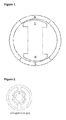
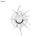
- the pole shoes of the stator ferromagnetic material can be shaped eccentrically or asymmetrically (see an example on figure 1 ).
- An aspect of the present invention is based on the realization that the shape of pole shoes at the stator are reflected in the BEMF waveform induced in the stator windings during rotation of the rotor permanent magnet and that the resulting waveform of the BEMF can be used to determine the direction of rotation of the rotor and determine the time instant where commutation of the current in the stator windings should be done (i.e. where the direction of the current in the stator windings must be changed).
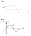
- the BEMF waveform is generally assumed to be sinusoidal (see figure 6 ) or trapezoidal with a flat top (see figure 7 ) and departure from these shapes are considered to be disturbances that must be compensated for to guarantee that the motor will be controlled adequately.
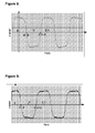
- FIG 8 and 9 An example of a BEMF waveform that is not sinusoidal or trapezoidal with a flat top can be seen on figure 8 and figure 9 as it was measured by the applicant on a general purpose single phase brushless DC motor with a tapered air gap.
- Figure 8 and 9 give the BEMF signal in function of the angular position of the rotor (at a substantially constant rotation speed). As expected, the BEMF signal has a trapezoidal shape but instead of being flat, the top of the trapezoid has a non zero slope which reflects the fact that the air gap is tapered.
- the waveforms on figure 8 and 9 correspond to opposite direction of rotation for the rotor.
- any brushless DC motor may, accidentally or not, exhibit a magnet dissymmetry or be magnetically deformed or the mechanical dissymmetry of the stator is not exactly the same as that of the rotor.
- the electric motor comprises a stator and a rotor, one or more set of windings and presents accidental or intentional asymmetry and/or eccentricity (e.g. dissymmetry or deformation of the permanent rotor magnet, deformed stator or mechanical dissymmetry between stator and rotor, ...) that influences the variation of the back electromotive force induced in said windings in function of the angular position of the rotor with respect to the stator.
- the motor can be a single phase brushless DC motor with a tapered air-gap as seen on figure 11 .
- the stator windings (111) (112) are wound around pole shoes (113) (114).
- the rotor (115) comprises a permanent magnet.
- the angular position of the rotor (115) is the angle ⁇ (118) between an axis of reference (117) that is fixed with respect to the stator (116) and the North - South axis (119) of the stator magnet.
- the axis of reference ( 117 ) is chosen so that ⁇ is equal to 0 (or an integer multiple of ⁇ ) when the North-South axis of the rotor permanent magnet is aligned with the magnetic field generated by the stator windings.
- the air gap between the rotor (115) and the pole shoes (113) and (114) is tapered. The tapered air gap may be intentional or accidental.
- the tapered air gap introduces an asymmetry in the distribution of the induction field lines and/or the local amplitude of the magnetic field that may help solve the "dead point" problem that was briefly discussed earlier.
- the method comprises the measurement of a signal that is either the back electromotive force or any other electrical signal that is a function of the back electromotive force and that reflects said asymmetry and/or eccentricity.
- the method is further characterized in that the slope of the amplitude of the signal at one or more moments in time is detected or derived to determine the direction of rotation of the motor.
- the method is further characterized in that the slope of the amplitude of the signal at a first moment in time is compared with the slope of the amplitude of the signal at a second moment in time.
- the method is further characterized in that an average value of the slope of the signal around a first moment in time is compared with an average value of the slope of the amplitude of the signal around a second moment in time.
- the method is further characterized in that the first and second moment in time are at or near a maximum of the amplitude of the signal.
- the first moment in time is before a maximum of the amplitude of the signal and the second moment in time is after said maximum.
- the signal used to determine the direction of rotation may be a signal that is function of the bemf and that reflects or follows the variation of the bemf.
- the signal may be the output of a regulator controlling the amplitude of the current in the electric motor .
- the signal is the duty cycle of a PWM regulator.
- BEMF back electromotive force
- BEMF back electromotive force
- BEMF back electromotive force
- BEMF back electromotive force
- the following convention will be used when describing the state of a switch and in particular transistor switch:
- the transistor (switch) will be said to be closed (as if it were a normal mechanical switch) when it allows current to flow through it. In other words, when the transistor switch is closed it is conducting.
- the transistor (switch) is then switched ON.
- the transistor (switch) will be said to be opened when it does not allow current to flow through it. In other words, when the transistor switch is opened it is not conducting.
- the transistor (switch) is then said to be switched OFF.
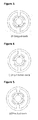
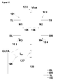
- the direction of the current in the stator windings of a single phase brushless DC motor is controlled by means of a full H-bridge as seen on figure 12 .
- the H-bridge comprises four switches that connect the stator windings (modelled as a coil 125 in series with a resistor 126) to a power supply Vbat (120).
- these switches may be MOSFET transistor switches M1 (121), M2 (122), M3 (123) and M4 (124).
- the transistor switches are controlled by the signals TL (Top Left), TR (Top Right), BL (Bottom Left), BR (Bottom Right) respectively applied to the gate of M1, M2, M3 and M4.
- the transistor switches are either on or off depending on the signal applied at their gate (high H or low L).
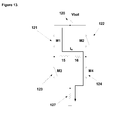
- M1 and M4 might be closed and M2 and M3 open.
- the current i w flows in the stator windings in a first direction (see figure 13 ).
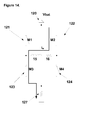
- M1 and M4 may be opened and M2 and M3 closed (see figure 14 ).
- the H-bridge is configured so as to force the current in an opposite direction (i.e.
- transistors M1 (121) and M4 (124) are opened and transistors M2 (122) and M3 (123) are closed.
- the amplitude of the current is measured by a sense resistor R sense ( 127 ) connected between a reference ground and the source of the transistor switches M3 (123) and M4 (124).
- a comparator (128) compares the voltage drop across the sense resistor (127) with a reference i Set to determine whether or not the amplitude of the current i w in the stator windings is lower or larger than a given value i Set .
- a regulator (129) uses the output of comparator (128) to generate control signals TL, TR, BL, BR in order to control the amplitude of the current i w and bring the amplitude of i w (as close as possible) to the given set value i Set .
- control loop is ensured by measuring the current I w with the sense resistor (127), the measured current is then compared with a set-point value I set with a comparator (128) (in general, one evaluates the difference between the measured value and the set-point value), the result is used as input to a regulator (129) that determines one or more control signals (TL, TR, BL, BR) to be applied to an actuator (the H-bridge).
- Pulse Width Modulation can be used to control the amplitude of the current i w in the stator windings.
- the supply voltage Vbat (120) is not applied continuously but only during a fraction of the time. As a result, everything happens as if the stator windings saw an average activation voltage that is a fraction of the supply voltage Vbat (120).
- Pulse Width Modulation instead of applying a continuous high signal e.g. TL to the gate of transistor M1 (121) and BR to the gate of transistor M4 (124) (while M2 (122) and M3 (123) are open, i.e. signals TR and BL are low), transistor e.g. M4 ( 124 ) is kept closed but transistor e.g. M1( 121 ) is switched on and off (see figure 15 ).
- transistor M4 ( 124 ) is kept closed but transistor M1 ( 121 ) is alternatively switched on and off while M2 (122) and M3 (123) are open.
- the switch (161) is e.g. either transistor M1 (element 121 in figure 12 ) when the current must flow in a first direction or M2 (element 122 in figure 12 ) (see figure 12 ) when the current must flow in a second direction
- the voltage source (162) represents the back electromotive force or bemf induced in the stator windings by the rotating permanent magnet at the rotor.
- the stator windings are modelled by the inductor (165) and the series resistor (166).
- a free wheeling diode (163) allows the current to circulate in the stator windings when the switch (161 ) is open.
- the freewheeling diode may be intentional or may be a parasitic diode of the transistor switches e.g. M3 or M4.
- the freewheeling diode 163 may be the parasitic diode associated with transistor M3.
- the freewheeling diode 163 may be the parasitic diode associated with transistor M4 .
- the transistors M3 and M4 are n-type MOS transistors (in which case, the bulk electrode is often, if not always, shorted with the source electrode) and in that case the drain-bulk diode of M3 or M4 can in some cases be used as freewheeling diode.
- the voltage source 160 is connected in series with the switch 161, the inductor 165 and the resistor 166. Note that the free wheeling diode (163) is not strictly necessary. One could indeed proceed with the available transistors.
- the role of a free wheeling diode like the diode (163) is to allow the current to circulate through the coil (165) when the switch (161) is open.
- the role of the free-wheeling diode may be assumed by one of the transistors M1, M2, M3 or M4 at the cost of slightly increased complexity in how the H-bridge is operated in PWM mode. For instance, let us assume that as seen on figure 13 and figure 15 transistors M1 and M4 are closed in order to allow / force the current I w to flow in a given direction.
- PWM mode as will be explained in greater detail here below, transistor M1 is repeatedly open and closed while transistor M4 remains closed. When transistor M1 is open, no current can flow from Vbat (120) through the stator windings (125). With a freewheeling diode connected in parallel with the stator windings (i.e.
- the current keeps flowing through the stator windings and through the freewheeling diode when transistor M1 is open.
- transistor switch M3 In absence of freewheeling diode, one can close the transistor switch M3 when transistor switch M1 is opened so that the current I w will flow through the loop 126, 125 - M4 - sense resistor 17 - GND - M4 - 16.
- the control signal (TL when transistor M1 (121) is used or TR when transistor M2 ( 122 ) is used) that opens or closes the switch 161 is as seen on figure 15 (see evolution of TL in function of the time) or 17 (see evolution of PWM Signal in function of time).
- L low level
- H high level
- the low and high levels are such that they can either close or open the switch to which they are applied.
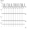
- Time is divided into intervals of equal length T PWM .
- the PWM signal also referred to as the control signal (e.g. TL or TR) in this first preferred embodiment is held high for a fraction of every time interval T PWM . That fraction may vary from one interval to the other.
- the control signals are generated by the regulator 129 (and in particular, as considered in this first embodiment, a PWM regulator) and must satisfy certain conditions. For instance, to avoid audible frequencies, the PWM frequency f PWM is chosen higher than the audible range.
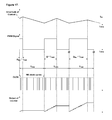
- the duty cycle DC will be defined as the fraction of the period T PWM during which the (full) supply voltage Vbat is applied to the stator windings. To avoid generation of sub-harmonics of the PWM signal in the audible range, duty cycles of 0 and 100% are excluded.
- duty cycle of 0% and 100% may be avoided as follows (see figure 17 ): the PWM signal is high at the beginning of a PWM period (for at least D Min * T PWM ) and is held high as long as the current in the coil has not reached a reference value I set as indicated by the output of comparator 128. Regardless of the current in the stator i w , after a time D Max * T PWM (* is the operator for multiplication) the output of the PWM is always set to 0 for the portion of the PWM period between D Max T PWM and the end of that PWM period. A typical value for D Max might be 0.75. A typical value for D Min might be 0.05.
- the PWM signal may be applied to either the gate of transistor M1 (121) or transistor M2 (122) depending on the required direction of the current.
- the duty cycle must increase accordingly: indeed, the bemf signal acts against the supply voltage.
- the duty cycle must decrease accordingly.
- the variation of the duty cycle DC "mirrors" the variation of the amplitude of the BEMF signal. Therefore, in a circuit like the one of figure 12 , information on the BEMF signal can be extracted from the duty cycle of the PWM signal.
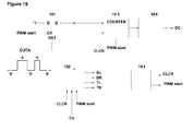
- a particular implementation of the regulator 129 can be seen on figure 18 .
- the output OUTA of the comparator 128 is used as reset signal for a D type flip flop 181 (i.e. the output Q of the flip flop is reset to the logical state '0' when the signal OUTA corresponds to a logical '0' corresponding to Iset ⁇ Iw).
- a pulse signal "PWM start” generated by an ad-hoc signal generator, determines the start of a PWM period and shifts a logical '1' signal from the D input to the Q output of flip-flop 181.
- the same "PWM start” signal reset a counter 183 (i.e. it sets the output of the counter 183 to a preset value).
- the counter 183 may for instance be a binary counter whose output consists of N counter bits that are made available either serially or in parallel. The output of the counter varies between 0 and 2 Ncounter -1.
- the signal on the Q output enables the counter 183 that counts the clock signal CLCK generated by the signal generator 184 at a frequency F CLCK higher than the frequency f PWM of the PWM.
- T PWM NB * T CLCK .
- the PWM period T PWM is e.g. 128 CLCK period long.
- the counter 183 is incremented by the clock signal CLCK as long as Q is high.
- Q which is the PWM signal is held high as long as the output OUTA of the comparator 128 is at logical '1' i.e. as long as the current i w in the stator windings is lower than the reference i set .
- the output of the counter equals the number of CLCK periods counted by the counter 183 and during which the PWM signal was high during that PWM period, i.e.
- the output of the counter at the end of a PWM period is proportional to the duty cycle (+/- 1/2 LSB i.e. NB*DC where LSB stands for Least Significant Bit and corresponds to the smallest possible increment for the output of the counter).
- LSB stands for Least Significant Bit and corresponds to the smallest possible increment for the output of the counter.
- Digital circuitry determines the signals BL, BR, TL and TR based on the signals Q, CLCK, PWM Start and the required direction of I Set (signal Dir). For example, if a first direction of the current is required, the block 182 will direct Q to the control electrode TR of transistor M2 (122), set BL to high (to close transistor M3) and set BR and TL to low (to open transistors M1 and M4). In absence of freewheeling diode, the block 182 will set the signal BR high or low in function of the state of signal TR (see above) to allow the current to circulate trough the stator windings while avoiding a short circuit from Vbat to GND.
- the block 182 will direct Q to the control electrode TL of transistor M1 (121), set BR to high (to close transistor M4) and set BL and TR to low (to open transistors M2 and M3). In absence of freewheeling diode, the block 182 will set the signal BL high or low in function of the state of signal TL (see above) to allow the current to circulate trough the stator windings while avoiding a short circuit from Vbat to GND.
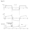
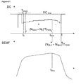
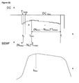
- FIG 19 An example of variation of the duty cycle DC and of the BEMF signal in function of the position of the rotor is seen on figure 19 .
- figure 19 we have taken a trapezoidal signal with a non flat top ABCD to model the BEMF without limitation of scope.
- the duty cycle DC of the PWM signal controlling the current in the motor increases as well and when the amplitude of the BEMF signal decreases, the duty cycle DC of the PWM signal controlling the current in the motor decreases as well.
- the duty cycle DC reaches a maximum as the amplitude of the BEMF signal reaches a maximum.
- a (steep) decrease of the amplitude of the BEMF signal and hence a (steep) decrease of the duty cycle DC indicates that the position of the rotor is close to a commutation point (the BEMF signal is about to crosses zero). Therefore, the decision to reverse the direction of the current is be taken e.g. when the duty cycle reaches a maximum (point C on figure 19 ) or shortly after the duty cycle has reached a maximum.
- a first possible direction for the current corresponds to that part of the graph representing Iw in function of ⁇ above the ⁇ -axis, i.e.
- the direction of the current I w will not change sign instantaneously: the amplitude of I w will first decrease until it reaches zero, the sign of I W will change (zero crossing) and its amplitude will grow again.
- the amplitude of I w will be smaller than I set (
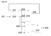
- Figure 20 gives a principle schematics of logic circuitry 200 that can be used to determine the commutation instants (whether the BEMF signal is symmetric or not, whther the BEMF signal can be modelled has a trapezoid with a fat top or a non flat top).
- a register 201 stores the highest value HDC of the duty cycle DC measured between an instant to and an instant t (with to ⁇ t).
- a comparator 205 compares the content 203 of the register 201 with the current DC 204 measured by the DC counter (and latch) 202, if the current DC 204 is higher than the content 203 of the register 201, the content of the register 201 is updated with the current DC 204.
- the difference between the current DC 204 and the content 203 of the register 201 is constantly evaluated and compared by a comparator 207 to a fraction of the content 203 of the register 201.
- a comparator 207 the difference between the current DC 204 and the content 203 of the register 201 is higher than a given percentage of the maximum value of the DC reached within the interval [to, t] the direction of the stator current is changed or in other words, if (HDC - current DC) > HDC / N , then the direction of the stator current is changed.
- the signal 208 indicating that the direction of the current must be changed is available at the output of the comparator 207.
- N will preferably be an integer number multiple of 2. This does not exclude other type of values for N in a general case.
- N can be considered as a sensitivity factor that determine how big variations of the duty cycle need to be to trigger commutation of the current in the stator windings. By varying the value of N, one can modify the instant at which commutation of the current in the stator windings is done and optimize the commutation of the current in function of the specificities of the motor.
- the content HDC of the register 201 is (re)-initialized to e.g. 0 at the instant the direction of the current in the stator winding is changed.
- the control loop will often overshoot and the duty cycle will reach its maximum value. To prevent the overshoot from being interpreted as a maximum of the BEMF signal that anticipates a commutation instant, some filtering is required.
- the duty cycle as measured between the instant to at which the register 201 has been last reset and the instant t 1 at which the direction of the current is changed may be used in various ways to determine cinematic quantities (e.g. angular displacement, angular speed, angular acceleration) and, when the BEMF signal is not symmetrical, the direction of rotation of the motor.
- the duty cycle DC is fed to a first filter 231 that performs filtering as described in the above.
- a counter 232 is incremented by one at each PWM period as long as the duty cycle DC has not reached its maximum.
- the counter 232 is decremented by one at each PWM period. The instant t may be determined as explained above e.g. based on the output of the circuit of figure 20 .
- the content of the counter is latched and if the latched content of counter 232 is positive, it means that the duty cycle DC has increased during a higher number of PWM period than the number of PWM period within which the duty cycle DC decreased. This is interpreted as the rotor moving in a first direction corresponding to the BEMF signal as seen on figure 21 . If on the contrary, the content of the counter 232 is found to be negative it means that the duty cycle DC has increased during a lower number of PWM period than the number of PWM period within which the duty cycle DC decreased. This is interpreted as the rotor moving in a second direction corresponding to the BEMF signal as seen on figure 22 .
- the duty cycle DC is first filtered by a filter 240 according to filtering criteria discussed earlier.
- the filter can for instance be synthesized with VHDL as known in the art based on the principle diagram on figure 20 .
- a clock 241 allows to measure time / time intervals.
- the filter 240 determines when to start taking measured duty cycle DC into account when looking for a maximum.
- the filter 240 determines the maximum duty cycle between the instant to and t. Be DC @ t Max , DC @ to and DC @t the maximum duty cycle, the duty cycle at the instant t0 and the duty cycle at the instant t as determined by the filter 240.
- Those three values are stored in registers 242 together with the corresponding time t0, t Max and t as measured by the clock 241.
- AARI1 the absolute value of a first average rate of increase of the duty cycle DC is computed between the instant t0 and the instant t Max .
- AARI1 may be approximated by an arithmetic unit 243 according to Eq. 3 here below:
- AARI ⁇ 1 DC ⁇ @ ⁇ t Max - DC ⁇ @ ⁇ t 0 / t Max - t 0
- AARI1 the absolute value of a second average rate of increase of the duty cycle DC is computed between the instant t0 and the instant t Max .
- AARI2 may be approximated by arithmetic unit 243 according to Eq. 4 here below:
- AARI ⁇ 2 DC ⁇ @ ⁇ t Max - DC ⁇ @ ⁇ t / t Max - t
- NMAX - N0 NMAX - NEND
- NMAX and NEND are the number of PWM periods that have elapsed at time to, t Max , and t respectively.
- N0 will be equal to 0.
- NMAX and NEND may easily be obtained by counting the number of PWM start signal generated by the signal generator 184 of figure 18 between t0 and t max , t0 and t respectively.
- the number of PWM periods may for instance be obtained by counting the signal PWM start in a number of ways known to the art.
- the filter and the clock may be part of a general purpose calculator 244 ⁇ (a microcontroller, a microprocessor, a microcomputer, ...) as seen on figure 23 .
- the quantities AARI1 and AARI2 may be computed directly from the BEMF signal as it would be measured or evaluated by a dedicated sensor e.g. the voltage drop across a coil sensor, said coil sensor may be the windings of a phase of a bipolar stepper motor when that phase is used as sensor to determine the position of the rotor of the stepper motor.
- the method proposed to determine the direction of rotation of a motor when the BEMF signal is mot symmetrical is hence not limited to a single phase stepper motor operated in PWM mode.
- Cinematic quantities like the angular displacement ⁇ and the angular speed ⁇ may be computed based on a analysis of the duty cycle signal and timing information provided by a clock. Starting from a first maximum duty cycle as detected by the filter 240, the content NbMax of a register is incremented and a refererence time t Ref is stored Whenever necessary, the angular displacement can be evaluated based on the value NbMax and the link that exist between the shape of the Bemf signal and the angular position of the rotor. For instance, when the bemf signal varies as illustrated on figure 10A , the angular displacement since t Ref will be approximated by (NbMax-1) * ⁇ . The angular speed ⁇ may be approximated by (NbMax-1) * ⁇ / (t NbMax - t ref ).
Landscapes
- Engineering & Computer Science (AREA)
- Power Engineering (AREA)
- Control Of Motors That Do Not Use Commutators (AREA)
Applications Claiming Priority (1)
| Application Number | Priority Date | Filing Date | Title |
|---|---|---|---|
| GBGB0700033.4A GB0700033D0 (en) | 2007-01-02 | 2007-01-02 | Method and apparatus for driving a brushless dc motor |
Publications (3)
| Publication Number | Publication Date |
|---|---|
| EP1942575A2 true EP1942575A2 (fr) | 2008-07-09 |
| EP1942575A3 EP1942575A3 (fr) | 2016-06-15 |
| EP1942575B1 EP1942575B1 (fr) | 2020-04-08 |
Family
ID=37759184
Family Applications (1)
| Application Number | Title | Priority Date | Filing Date |
|---|---|---|---|
| EP08100002.8A Not-in-force EP1942575B1 (fr) | 2007-01-02 | 2008-01-02 | Procédé et dispositif pour commander un moteur à courant continu |
Country Status (6)
| Country | Link |
|---|---|
| US (1) | US7592764B2 (fr) |
| EP (1) | EP1942575B1 (fr) |
| JP (1) | JP5411428B2 (fr) |
| CN (1) | CN101232267B (fr) |
| GB (1) | GB0700033D0 (fr) |
| TW (1) | TWI451688B (fr) |
Cited By (10)
| Publication number | Priority date | Publication date | Assignee | Title |
|---|---|---|---|---|
| ITTO20080616A1 (it) * | 2008-08-05 | 2010-02-06 | Bitron Spa | Procedimento per il controllo di un motore brushless in c.c. a due fasi senza sensore di posizione |
| EP3133723A1 (fr) * | 2015-08-18 | 2017-02-22 | Johnson Electric S.A. | Dispositif de génération de fluide et appareil électrique utilisant celui-ci |
| EP3136547A1 (fr) * | 2015-08-28 | 2017-03-01 | Johnson Electric S.A. | Moteur à phase unique |
| EP3136568A1 (fr) * | 2015-08-28 | 2017-03-01 | Johnson Electric S.A. | Moteur à aimant permanent à phase unique et son procédé de fabrication |
| EP3154177A1 (fr) * | 2015-10-09 | 2017-04-12 | Johnson Electric S.A. | Dispositif de regulation de debit d'air |
| US20170099929A1 (en) * | 2015-10-09 | 2017-04-13 | Johnson Electric S.A. | Hair Dryer |
| US10734850B2 (en) | 2013-08-09 | 2020-08-04 | Johnson Electric International AG | Single-phase motor |
| EP3937367A4 (fr) * | 2019-03-04 | 2022-05-04 | Mitsubishi Electric Corporation | Dispositif d'entraînement de moteur, ventilateur électrique, aspirateur électrique et sèche-mains |
| DE102009029396B4 (de) | 2009-09-11 | 2024-11-14 | Robert Bosch Gmbh | Verfahren zum Betreiben einer elektrischen Maschine |
| WO2025170947A1 (fr) * | 2024-02-05 | 2025-08-14 | Siemens Healthcare Diagnostics Inc. | Commande de moteur à courant continu sans balai à l'aide d'une extraction de signal de force contre-électromotrice |
Families Citing this family (36)
| Publication number | Priority date | Publication date | Assignee | Title |
|---|---|---|---|---|
| US8465151B2 (en) | 2003-04-15 | 2013-06-18 | Ipventure, Inc. | Eyewear with multi-part temple for supporting one or more electrical components |
| US7759894B2 (en) * | 2006-10-26 | 2010-07-20 | Honeywell International Inc. | Cogless motor driven active user interface haptic feedback system |
| US7969108B2 (en) * | 2008-12-03 | 2011-06-28 | Semiconductor Components Industries, Llc | Control circuit for a brushless DC motor and method therefor |
| EP2236838B1 (fr) * | 2009-03-25 | 2016-09-21 | ebm-papst Mulfingen GmbH & Co. KG | Ventilateur radial |
| DE102009040139B4 (de) | 2009-09-05 | 2012-10-04 | Trinamic Motion Control Gmbh & Co. Kg | Verfahren und Schaltungsanordnung zur sensorlosen Motorlasterfassung und zur lastwertabhängigen Motorstromregelung bei Schrittmotoren |
| FR2961966B1 (fr) * | 2010-06-25 | 2012-07-13 | Valeo Sys Controle Moteur Sas | Procede de charge de moyens d'accumulation et dispositif de charge correspondant |
| WO2012062376A1 (fr) | 2010-11-12 | 2012-05-18 | Abb Research Ltd | Machine électrique rotative et procédé correspondant |
| TWI422137B (zh) * | 2010-12-23 | 2014-01-01 | Amtek Semiconductor Co Ltd | 無微控制裝置之可調整輸出pwm控制訊號的馬達驅動模組及馬達控制系統 |
| DE102011017517A1 (de) * | 2011-04-26 | 2012-10-31 | Robert Bosch Gmbh | Verfahren zur sensorlosen Kommutierungserkennung von elektronisch kommutierten Elektromotoren |
| FR2975446B1 (fr) * | 2011-05-16 | 2016-06-24 | Bernard Perriere | Turbine a rendement optimise |
| US8901868B2 (en) * | 2011-05-18 | 2014-12-02 | Atmel Corporation | Starting sensorless brushless direct-current (BLDC) motors based on current-ripple analysis |
| JP5904523B2 (ja) * | 2011-06-14 | 2016-04-13 | セミコンダクター・コンポーネンツ・インダストリーズ・リミテッド・ライアビリティ・カンパニー | 単相ブラシレスモータの駆動回路 |
| DE102012105362A1 (de) * | 2012-06-20 | 2013-12-24 | Trinamic Motion Control Gmbh & Co. Kg | Verfahren und Schaltungsanordnung zur Ansteuerung eines Schrittmotors |
| US9294030B2 (en) * | 2013-02-06 | 2016-03-22 | Stmicroelectronics S.R.L. | Method of PWM regulation of a continuous current electric motor |
| CN103259469A (zh) * | 2013-04-19 | 2013-08-21 | 杭州微光电子股份有限公司 | 一种电子换向无刷直流单相风机电路及其控制方法 |
| CN103929162B (zh) * | 2014-04-30 | 2017-09-26 | 杭州士兰微电子股份有限公司 | 栅极驱动电路、功率开关电路以及栅极驱动方法 |
| DE102014108637A1 (de) * | 2014-06-18 | 2015-12-24 | Trinamic Motion Control Gmbh & Co. Kg | Verfahren und Schaltungsanordnung zum Ansteuern eines Schrittmotors |
| US10371171B2 (en) * | 2014-09-22 | 2019-08-06 | Regal Beloit America, Inc. | System and methods for reducing noise in an air moving system |
| MX2016006402A (es) * | 2015-05-21 | 2016-11-21 | Johnson Electric Sa | Motor monofasico, dispositivo generador de flujo de aire, y aparato electrico. |
| CN106469966A (zh) * | 2015-08-18 | 2017-03-01 | 德昌电机(深圳)有限公司 | 气流产生装置及吸尘器、干手器、干发器、吹风机 |
| DE102016113934A1 (de) * | 2015-08-18 | 2017-02-23 | Johnson Electric S.A. | Elektrowerkzeug mit bürstenlosem Einphasenmotor |
| CN106487186A (zh) * | 2015-08-28 | 2017-03-08 | 德昌电机(深圳)有限公司 | 单相永磁电机 |
| DE102016115366A1 (de) | 2015-08-28 | 2017-03-02 | Johnson Electric S.A. | Einphasiger Permanentmagnetmotor |
| CN106533000A (zh) * | 2015-09-10 | 2017-03-22 | 德昌电机(深圳)有限公司 | 单相永磁电机 |
| US10308307B2 (en) * | 2016-02-16 | 2019-06-04 | Allied Treasure Inc., Limited | Disk-type electric motor, electrically driven vehicle and method for controlling the same |
| CN109001629B (zh) * | 2018-07-05 | 2020-10-27 | 青岛艾普智能仪器有限公司 | 一种电机的反电动势测试方法 |
| CN111293794B (zh) * | 2018-12-06 | 2023-11-21 | 威灵(芜湖)电机制造有限公司 | 定子齿、定子及电机 |
| EP3741405A1 (fr) * | 2019-05-23 | 2020-11-25 | Ypsomed AG | Dispositif de distribution avec une commande de moteur sans capteur |
| CN110868115B (zh) * | 2019-10-28 | 2022-04-29 | 深圳市汇川技术股份有限公司 | 适用于无传感控制的电机 |
| CN112383250A (zh) * | 2020-11-10 | 2021-02-19 | 陈波 | 一种单相直流无刷无位置传感器电机用驱动电路 |
| CN112398241B (zh) * | 2020-11-10 | 2023-06-20 | 陈波 | 一种单相直流无刷无位置传感器电机及其构成的风扇 |
| US20220209693A1 (en) * | 2020-12-28 | 2022-06-30 | Global Mixed-Mode Technology Inc. | Motor unit |
| TWI780592B (zh) * | 2021-02-17 | 2022-10-11 | 致新科技股份有限公司 | 馬達單元 |
| US11362607B1 (en) | 2021-02-18 | 2022-06-14 | Global Mixed-Mode Technology Inc. | Motor unit |
| CN115356626B (zh) * | 2022-08-16 | 2025-09-23 | 苏州保邦电气有限公司 | 一种电机的检测方法、装置及磁悬浮电机 |
| TWI798151B (zh) * | 2022-08-29 | 2023-04-01 | 茂達電子股份有限公司 | 馬達正反轉偵測器以及具有馬達正反轉偵測器的馬達驅動器 |
Citations (3)
| Publication number | Priority date | Publication date | Assignee | Title |
|---|---|---|---|---|
| US5986419A (en) | 1996-07-15 | 1999-11-16 | General Electric Company | Quadrature axis winding for sensorless rotor angular position control of single phase permanent magnet motor |
| US6577085B2 (en) | 1998-02-11 | 2003-06-10 | Stmicroelectronics S.A. | Control of a brushless motor |
| US20060197478A1 (en) | 2005-03-02 | 2006-09-07 | Delta Electronics Inc. | Method for starting single phase BLDCM having asymmetrical air gap |
Family Cites Families (10)
| Publication number | Priority date | Publication date | Assignee | Title |
|---|---|---|---|---|
| JP3279333B2 (ja) * | 1992-02-20 | 2002-04-30 | 日本電産株式会社 | 2相ユニポーラセンサレスモータの回転方向識別方法 |
| US5696430A (en) * | 1993-02-22 | 1997-12-09 | General Electric Company | Circuit, motor, and method generating a signal representing back EMF in an energized motor winding |
| JPH09294391A (ja) * | 1996-04-25 | 1997-11-11 | Aichi Electric Co Ltd | センサレスブラシレスdcモータの速度制御装置 |
| US6160368A (en) * | 1998-06-22 | 2000-12-12 | Western Digital Corporation | Faster spin-down operation in a disk drive by utilizing pulsed braking |
| DE69927373D1 (de) * | 1999-09-30 | 2005-10-27 | St Microelectronics Srl | Zitterfreie Erkennung von Strom- oder Spannungs-Signalen an mit Pulswechselmodulation betriebener Wicklung |
| JP2003348875A (ja) * | 2002-05-27 | 2003-12-05 | Matsushita Electric Ind Co Ltd | 電動機駆動装置 |
| GB0317629D0 (en) * | 2003-07-28 | 2003-08-27 | Ami Semiconductor Belgium Bvba | Control of current in an inductance with pulse width modulation at controlled frequency |
| ATE507610T1 (de) * | 2004-05-12 | 2011-05-15 | Ebm Papst St Georgen Gmbh & Co | Verfahren zum sensorlosen betrieb eines elektronisch kommutierten motors, und motor zur durchführung eines solchen verfahrens |
| KR101041072B1 (ko) * | 2004-07-01 | 2011-06-13 | 삼성전자주식회사 | 브러시리스 직류 모터의 제어 방법 |
| JP2006050805A (ja) * | 2004-08-05 | 2006-02-16 | Matsushita Electric Ind Co Ltd | ブラシレスdcモータ駆動装置 |
-
2007
- 2007-01-02 GB GBGB0700033.4A patent/GB0700033D0/en not_active Ceased
- 2007-12-26 TW TW096150210A patent/TWI451688B/zh active
- 2007-12-27 JP JP2007337556A patent/JP5411428B2/ja active Active
- 2007-12-27 CN CN2007103035680A patent/CN101232267B/zh active Active
-
2008
- 2008-01-02 EP EP08100002.8A patent/EP1942575B1/fr not_active Not-in-force
- 2008-01-02 US US11/968,591 patent/US7592764B2/en active Active
Patent Citations (3)
| Publication number | Priority date | Publication date | Assignee | Title |
|---|---|---|---|---|
| US5986419A (en) | 1996-07-15 | 1999-11-16 | General Electric Company | Quadrature axis winding for sensorless rotor angular position control of single phase permanent magnet motor |
| US6577085B2 (en) | 1998-02-11 | 2003-06-10 | Stmicroelectronics S.A. | Control of a brushless motor |
| US20060197478A1 (en) | 2005-03-02 | 2006-09-07 | Delta Electronics Inc. | Method for starting single phase BLDCM having asymmetrical air gap |
Non-Patent Citations (2)
| Title |
|---|
| "A Full-Wave Motor Drive IC Based on The Back-EMF Sensing Principle", IEEE TRANSACTIONS ON CONSUMER ELECTRONICS, vol. 35, 3 August 1989 (1989-08-03), pages 415 - 420 |
| GABRIEL CIMUCA: "Proceedings of the 8th International Conference on Optimization of Electrical and Electronic Equipments", 2002, UNIVERSITY PRESS, article "Back-EMF estimation approach for Sensorless operation of small electronically co", pages: 509 - 512 |
Cited By (11)
| Publication number | Priority date | Publication date | Assignee | Title |
|---|---|---|---|---|
| ITTO20080616A1 (it) * | 2008-08-05 | 2010-02-06 | Bitron Spa | Procedimento per il controllo di un motore brushless in c.c. a due fasi senza sensore di posizione |
| DE102009029396B4 (de) | 2009-09-11 | 2024-11-14 | Robert Bosch Gmbh | Verfahren zum Betreiben einer elektrischen Maschine |
| US10734850B2 (en) | 2013-08-09 | 2020-08-04 | Johnson Electric International AG | Single-phase motor |
| EP3133723A1 (fr) * | 2015-08-18 | 2017-02-22 | Johnson Electric S.A. | Dispositif de génération de fluide et appareil électrique utilisant celui-ci |
| US10389217B2 (en) | 2015-08-18 | 2019-08-20 | Johnson Electric International AG | Fluid generating device and electric apparatus using the same |
| EP3136547A1 (fr) * | 2015-08-28 | 2017-03-01 | Johnson Electric S.A. | Moteur à phase unique |
| EP3136568A1 (fr) * | 2015-08-28 | 2017-03-01 | Johnson Electric S.A. | Moteur à aimant permanent à phase unique et son procédé de fabrication |
| EP3154177A1 (fr) * | 2015-10-09 | 2017-04-12 | Johnson Electric S.A. | Dispositif de regulation de debit d'air |
| US20170099929A1 (en) * | 2015-10-09 | 2017-04-13 | Johnson Electric S.A. | Hair Dryer |
| EP3937367A4 (fr) * | 2019-03-04 | 2022-05-04 | Mitsubishi Electric Corporation | Dispositif d'entraînement de moteur, ventilateur électrique, aspirateur électrique et sèche-mains |
| WO2025170947A1 (fr) * | 2024-02-05 | 2025-08-14 | Siemens Healthcare Diagnostics Inc. | Commande de moteur à courant continu sans balai à l'aide d'une extraction de signal de force contre-électromotrice |
Also Published As
| Publication number | Publication date |
|---|---|
| GB0700033D0 (en) | 2007-02-07 |
| US7592764B2 (en) | 2009-09-22 |
| CN101232267B (zh) | 2012-07-04 |
| EP1942575A3 (fr) | 2016-06-15 |
| TW200838119A (en) | 2008-09-16 |
| EP1942575B1 (fr) | 2020-04-08 |
| JP5411428B2 (ja) | 2014-02-12 |
| CN101232267A (zh) | 2008-07-30 |
| JP2008167648A (ja) | 2008-07-17 |
| TWI451688B (zh) | 2014-09-01 |
| US20080197794A1 (en) | 2008-08-21 |
Similar Documents
| Publication | Publication Date | Title |
|---|---|---|
| EP1942575B1 (fr) | Procédé et dispositif pour commander un moteur à courant continu | |
| JP6375431B2 (ja) | 永久磁石モータのロータ位置の決定方法 | |
| JP2875529B2 (ja) | センサレスブラシレスモータの駆動装置 | |
| JP5749288B2 (ja) | ブラシレス永久磁石モータのセンサレス制御 | |
| US8531145B2 (en) | Sensorless technology, estimation of sampled back EMF voltage values and/or the sampled inductance values based on the pulse width modulation periods | |
| CN100375384C (zh) | 磁阻电机的控制 | |
| KR101446662B1 (ko) | 전기 기계의 제어 | |
| US8917044B2 (en) | Electronic circuit and method for detecting a zero current in a winding of an electric motor | |
| CN104285369B (zh) | 确定永磁电机的转子位置的方法 | |
| EP2876807B1 (fr) | Régulation de courant de phase dans des moteurs BLDC | |
| CN104067508B (zh) | 控制无刷电机的方法 | |
| KR20200010600A (ko) | 전기 모터의 권선 내에 검출되는 영전류에 따라 전기 모터에 인가되는 구동 신호의 위상을 자동적으로 조정하고 영전류를 검출하기 위한 전기 회로 및 방법 | |
| CN108111063A (zh) | 减小无刷电机的功率消耗 | |
| WO2010076665A1 (fr) | Circuit et procédé de surveillance de régime d'un moteur électrique | |
| Yadav et al. | Position and speed control of brushless DC motors using sensorless techniques: A review | |
| CN113169685B (zh) | 控制无刷永磁电机的方法 | |
| KR100474955B1 (ko) | 중성점 전압 보상을 기반으로 한 비엘디씨 모터의 제어시스템 및 그 방법 | |
| DiRenzo | Developing an SRM Drive System using the TMS320F240 | |
| Gorbounov | Digital Control of Switched Reluctance Motors Based on Programmable Logic | |
| KR20040012383A (ko) | 에스알엠의 상권선 병렬운전 | |
| Howe et al. | Simulation of permanent magnet motor drives | |
| HK1133958B (en) | Sensorless technology, estimation of sampled back emf voltage values and/or the sampled inductance values based on the pulse width modulation periods |
Legal Events
| Date | Code | Title | Description |
|---|---|---|---|
| PUAI | Public reference made under article 153(3) epc to a published international application that has entered the european phase |
Free format text: ORIGINAL CODE: 0009012 |
|
| AK | Designated contracting states |
Kind code of ref document: A2 Designated state(s): AT BE BG CH CY CZ DE DK EE ES FI FR GB GR HR HU IE IS IT LI LT LU LV MC MT NL NO PL PT RO SE SI SK TR |
|
| AX | Request for extension of the european patent |
Extension state: AL BA MK RS |
|
| RAP1 | Party data changed (applicant data changed or rights of an application transferred) |
Owner name: SEMICONDUCTOR COMPONENTS INDUSTRIES, LLC |
|
| PUAL | Search report despatched |
Free format text: ORIGINAL CODE: 0009013 |
|
| AK | Designated contracting states |
Kind code of ref document: A3 Designated state(s): AT BE BG CH CY CZ DE DK EE ES FI FR GB GR HR HU IE IS IT LI LT LU LV MC MT NL NO PL PT RO SE SI SK TR |
|
| AX | Request for extension of the european patent |
Extension state: AL BA MK RS |
|
| RIC1 | Information provided on ipc code assigned before grant |
Ipc: H02P 6/18 20160101AFI20160510BHEP |
|
| STAA | Information on the status of an ep patent application or granted ep patent |
Free format text: STATUS: REQUEST FOR EXAMINATION WAS MADE |
|
| 17P | Request for examination filed |
Effective date: 20161215 |
|
| RBV | Designated contracting states (corrected) |
Designated state(s): AT BE BG CH CY CZ DE DK EE ES FI FR GB GR HR HU IE IS IT LI LT LU LV MC MT NL NO PL PT RO SE SI SK TR |
|
| AKX | Designation fees paid |
Designated state(s): AT BE BG CH CY CZ DE DK EE ES FI FR GB GR HR HU IE IS IT LI LT LU LV MC MT NL NO PL PT RO SE SI SK TR |
|
| AXX | Extension fees paid |
Extension state: AL Extension state: MK Extension state: RS Extension state: BA |
|
| REG | Reference to a national code |
Ref country code: DE Ref legal event code: R079 Ref document number: 602008062464 Country of ref document: DE Free format text: PREVIOUS MAIN CLASS: H02P0006180000 Ipc: H02P0006080000 |
|
| RIC1 | Information provided on ipc code assigned before grant |
Ipc: H02P 6/182 20160101ALI20190926BHEP Ipc: H02P 6/30 20160101ALI20190926BHEP Ipc: H02P 6/08 20160101AFI20190926BHEP Ipc: H02P 6/28 20160101ALI20190926BHEP Ipc: H02P 6/18 20160101ALI20190926BHEP |
|
| GRAP | Despatch of communication of intention to grant a patent |
Free format text: ORIGINAL CODE: EPIDOSNIGR1 |
|
| STAA | Information on the status of an ep patent application or granted ep patent |
Free format text: STATUS: GRANT OF PATENT IS INTENDED |
|
| INTG | Intention to grant announced |
Effective date: 20191105 |
|
| GRAS | Grant fee paid |
Free format text: ORIGINAL CODE: EPIDOSNIGR3 |
|
| GRAA | (expected) grant |
Free format text: ORIGINAL CODE: 0009210 |
|
| STAA | Information on the status of an ep patent application or granted ep patent |
Free format text: STATUS: THE PATENT HAS BEEN GRANTED |
|
| AK | Designated contracting states |
Kind code of ref document: B1 Designated state(s): AT BE BG CH CY CZ DE DK EE ES FI FR GB GR HR HU IE IS IT LI LT LU LV MC MT NL NO PL PT RO SE SI SK TR |
|
| REG | Reference to a national code |
Ref country code: GB Ref legal event code: FG4D |
|
| REG | Reference to a national code |
Ref country code: AT Ref legal event code: REF Ref document number: 1255717 Country of ref document: AT Kind code of ref document: T Effective date: 20200415 Ref country code: CH Ref legal event code: EP |
|
| REG | Reference to a national code |
Ref country code: DE Ref legal event code: R096 Ref document number: 602008062464 Country of ref document: DE |
|
| REG | Reference to a national code |
Ref country code: IE Ref legal event code: FG4D |
|
| REG | Reference to a national code |
Ref country code: NL Ref legal event code: MP Effective date: 20200408 |
|
| REG | Reference to a national code |
Ref country code: LT Ref legal event code: MG4D |
|
| PG25 | Lapsed in a contracting state [announced via postgrant information from national office to epo] |
Ref country code: LT Free format text: LAPSE BECAUSE OF FAILURE TO SUBMIT A TRANSLATION OF THE DESCRIPTION OR TO PAY THE FEE WITHIN THE PRESCRIBED TIME-LIMIT Effective date: 20200408 Ref country code: NL Free format text: LAPSE BECAUSE OF FAILURE TO SUBMIT A TRANSLATION OF THE DESCRIPTION OR TO PAY THE FEE WITHIN THE PRESCRIBED TIME-LIMIT Effective date: 20200408 Ref country code: NO Free format text: LAPSE BECAUSE OF FAILURE TO SUBMIT A TRANSLATION OF THE DESCRIPTION OR TO PAY THE FEE WITHIN THE PRESCRIBED TIME-LIMIT Effective date: 20200708 Ref country code: SE Free format text: LAPSE BECAUSE OF FAILURE TO SUBMIT A TRANSLATION OF THE DESCRIPTION OR TO PAY THE FEE WITHIN THE PRESCRIBED TIME-LIMIT Effective date: 20200408 Ref country code: GR Free format text: LAPSE BECAUSE OF FAILURE TO SUBMIT A TRANSLATION OF THE DESCRIPTION OR TO PAY THE FEE WITHIN THE PRESCRIBED TIME-LIMIT Effective date: 20200709 Ref country code: IS Free format text: LAPSE BECAUSE OF FAILURE TO SUBMIT A TRANSLATION OF THE DESCRIPTION OR TO PAY THE FEE WITHIN THE PRESCRIBED TIME-LIMIT Effective date: 20200808 Ref country code: FI Free format text: LAPSE BECAUSE OF FAILURE TO SUBMIT A TRANSLATION OF THE DESCRIPTION OR TO PAY THE FEE WITHIN THE PRESCRIBED TIME-LIMIT Effective date: 20200408 Ref country code: PT Free format text: LAPSE BECAUSE OF FAILURE TO SUBMIT A TRANSLATION OF THE DESCRIPTION OR TO PAY THE FEE WITHIN THE PRESCRIBED TIME-LIMIT Effective date: 20200817 |
|
| REG | Reference to a national code |
Ref country code: AT Ref legal event code: MK05 Ref document number: 1255717 Country of ref document: AT Kind code of ref document: T Effective date: 20200408 |
|
| PG25 | Lapsed in a contracting state [announced via postgrant information from national office to epo] |
Ref country code: LV Free format text: LAPSE BECAUSE OF FAILURE TO SUBMIT A TRANSLATION OF THE DESCRIPTION OR TO PAY THE FEE WITHIN THE PRESCRIBED TIME-LIMIT Effective date: 20200408 Ref country code: HR Free format text: LAPSE BECAUSE OF FAILURE TO SUBMIT A TRANSLATION OF THE DESCRIPTION OR TO PAY THE FEE WITHIN THE PRESCRIBED TIME-LIMIT Effective date: 20200408 Ref country code: BG Free format text: LAPSE BECAUSE OF FAILURE TO SUBMIT A TRANSLATION OF THE DESCRIPTION OR TO PAY THE FEE WITHIN THE PRESCRIBED TIME-LIMIT Effective date: 20200708 |
|
| REG | Reference to a national code |
Ref country code: DE Ref legal event code: R097 Ref document number: 602008062464 Country of ref document: DE |
|
| PG25 | Lapsed in a contracting state [announced via postgrant information from national office to epo] |
Ref country code: RO Free format text: LAPSE BECAUSE OF FAILURE TO SUBMIT A TRANSLATION OF THE DESCRIPTION OR TO PAY THE FEE WITHIN THE PRESCRIBED TIME-LIMIT Effective date: 20200408 Ref country code: CZ Free format text: LAPSE BECAUSE OF FAILURE TO SUBMIT A TRANSLATION OF THE DESCRIPTION OR TO PAY THE FEE WITHIN THE PRESCRIBED TIME-LIMIT Effective date: 20200408 Ref country code: EE Free format text: LAPSE BECAUSE OF FAILURE TO SUBMIT A TRANSLATION OF THE DESCRIPTION OR TO PAY THE FEE WITHIN THE PRESCRIBED TIME-LIMIT Effective date: 20200408 Ref country code: IT Free format text: LAPSE BECAUSE OF FAILURE TO SUBMIT A TRANSLATION OF THE DESCRIPTION OR TO PAY THE FEE WITHIN THE PRESCRIBED TIME-LIMIT Effective date: 20200408 Ref country code: DK Free format text: LAPSE BECAUSE OF FAILURE TO SUBMIT A TRANSLATION OF THE DESCRIPTION OR TO PAY THE FEE WITHIN THE PRESCRIBED TIME-LIMIT Effective date: 20200408 Ref country code: AT Free format text: LAPSE BECAUSE OF FAILURE TO SUBMIT A TRANSLATION OF THE DESCRIPTION OR TO PAY THE FEE WITHIN THE PRESCRIBED TIME-LIMIT Effective date: 20200408 Ref country code: ES Free format text: LAPSE BECAUSE OF FAILURE TO SUBMIT A TRANSLATION OF THE DESCRIPTION OR TO PAY THE FEE WITHIN THE PRESCRIBED TIME-LIMIT Effective date: 20200408 |
|
| PGFP | Annual fee paid to national office [announced via postgrant information from national office to epo] |
Ref country code: FR Payment date: 20201217 Year of fee payment: 14 |
|
| PLBE | No opposition filed within time limit |
Free format text: ORIGINAL CODE: 0009261 |
|
| STAA | Information on the status of an ep patent application or granted ep patent |
Free format text: STATUS: NO OPPOSITION FILED WITHIN TIME LIMIT |
|
| PG25 | Lapsed in a contracting state [announced via postgrant information from national office to epo] |
Ref country code: SK Free format text: LAPSE BECAUSE OF FAILURE TO SUBMIT A TRANSLATION OF THE DESCRIPTION OR TO PAY THE FEE WITHIN THE PRESCRIBED TIME-LIMIT Effective date: 20200408 Ref country code: PL Free format text: LAPSE BECAUSE OF FAILURE TO SUBMIT A TRANSLATION OF THE DESCRIPTION OR TO PAY THE FEE WITHIN THE PRESCRIBED TIME-LIMIT Effective date: 20200408 |
|
| PGFP | Annual fee paid to national office [announced via postgrant information from national office to epo] |
Ref country code: BE Payment date: 20201222 Year of fee payment: 14 |
|
| 26N | No opposition filed |
Effective date: 20210112 |
|
| PG25 | Lapsed in a contracting state [announced via postgrant information from national office to epo] |
Ref country code: SI Free format text: LAPSE BECAUSE OF FAILURE TO SUBMIT A TRANSLATION OF THE DESCRIPTION OR TO PAY THE FEE WITHIN THE PRESCRIBED TIME-LIMIT Effective date: 20200408 |
|
| PGFP | Annual fee paid to national office [announced via postgrant information from national office to epo] |
Ref country code: DE Payment date: 20201217 Year of fee payment: 14 |
|
| PG25 | Lapsed in a contracting state [announced via postgrant information from national office to epo] |
Ref country code: MC Free format text: LAPSE BECAUSE OF FAILURE TO SUBMIT A TRANSLATION OF THE DESCRIPTION OR TO PAY THE FEE WITHIN THE PRESCRIBED TIME-LIMIT Effective date: 20200408 |
|
| REG | Reference to a national code |
Ref country code: CH Ref legal event code: PL |
|
| GBPC | Gb: european patent ceased through non-payment of renewal fee |
Effective date: 20210102 |
|
| PG25 | Lapsed in a contracting state [announced via postgrant information from national office to epo] |
Ref country code: LU Free format text: LAPSE BECAUSE OF NON-PAYMENT OF DUE FEES Effective date: 20210102 |
|
| PG25 | Lapsed in a contracting state [announced via postgrant information from national office to epo] |
Ref country code: GB Free format text: LAPSE BECAUSE OF NON-PAYMENT OF DUE FEES Effective date: 20210102 Ref country code: CH Free format text: LAPSE BECAUSE OF NON-PAYMENT OF DUE FEES Effective date: 20210131 Ref country code: LI Free format text: LAPSE BECAUSE OF NON-PAYMENT OF DUE FEES Effective date: 20210131 |
|
| PG25 | Lapsed in a contracting state [announced via postgrant information from national office to epo] |
Ref country code: IE Free format text: LAPSE BECAUSE OF NON-PAYMENT OF DUE FEES Effective date: 20210102 |
|
| REG | Reference to a national code |
Ref country code: DE Ref legal event code: R119 Ref document number: 602008062464 Country of ref document: DE |
|
| REG | Reference to a national code |
Ref country code: BE Ref legal event code: MM Effective date: 20220131 |
|
| PG25 | Lapsed in a contracting state [announced via postgrant information from national office to epo] |
Ref country code: DE Free format text: LAPSE BECAUSE OF NON-PAYMENT OF DUE FEES Effective date: 20220802 |
|
| PG25 | Lapsed in a contracting state [announced via postgrant information from national office to epo] |
Ref country code: FR Free format text: LAPSE BECAUSE OF NON-PAYMENT OF DUE FEES Effective date: 20220131 Ref country code: BE Free format text: LAPSE BECAUSE OF NON-PAYMENT OF DUE FEES Effective date: 20220131 |
|
| PG25 | Lapsed in a contracting state [announced via postgrant information from national office to epo] |
Ref country code: HU Free format text: LAPSE BECAUSE OF FAILURE TO SUBMIT A TRANSLATION OF THE DESCRIPTION OR TO PAY THE FEE WITHIN THE PRESCRIBED TIME-LIMIT; INVALID AB INITIO Effective date: 20080102 Ref country code: CY Free format text: LAPSE BECAUSE OF FAILURE TO SUBMIT A TRANSLATION OF THE DESCRIPTION OR TO PAY THE FEE WITHIN THE PRESCRIBED TIME-LIMIT Effective date: 20200408 |
|
| PG25 | Lapsed in a contracting state [announced via postgrant information from national office to epo] |
Ref country code: TR Free format text: LAPSE BECAUSE OF FAILURE TO SUBMIT A TRANSLATION OF THE DESCRIPTION OR TO PAY THE FEE WITHIN THE PRESCRIBED TIME-LIMIT Effective date: 20200408 |
|
| PG25 | Lapsed in a contracting state [announced via postgrant information from national office to epo] |
Ref country code: MT Free format text: LAPSE BECAUSE OF FAILURE TO SUBMIT A TRANSLATION OF THE DESCRIPTION OR TO PAY THE FEE WITHIN THE PRESCRIBED TIME-LIMIT Effective date: 20200408 |