EP1942383B1 - Self-cleaning image forming apparatus - Google Patents
Self-cleaning image forming apparatus Download PDFInfo
- Publication number
- EP1942383B1 EP1942383B1 EP08153374A EP08153374A EP1942383B1 EP 1942383 B1 EP1942383 B1 EP 1942383B1 EP 08153374 A EP08153374 A EP 08153374A EP 08153374 A EP08153374 A EP 08153374A EP 1942383 B1 EP1942383 B1 EP 1942383B1
- Authority
- EP
- European Patent Office
- Prior art keywords
- toner
- intermediate transfer
- image
- transfer
- image bearing
- Prior art date
- Legal status (The legal status is an assumption and is not a legal conclusion. Google has not performed a legal analysis and makes no representation as to the accuracy of the status listed.)
- Expired - Lifetime
Links
- 238000004140 cleaning Methods 0.000 title description 58
- 238000012546 transfer Methods 0.000 claims description 270
- 230000005684 electric field Effects 0.000 claims description 5
- 230000032258 transport Effects 0.000 description 72
- 230000015572 biosynthetic process Effects 0.000 description 36
- 230000002093 peripheral effect Effects 0.000 description 32
- 239000002699 waste material Substances 0.000 description 15
- 238000000034 method Methods 0.000 description 11
- 230000008569 process Effects 0.000 description 9
- 238000001514 detection method Methods 0.000 description 7
- 239000000470 constituent Substances 0.000 description 4
- 238000005299 abrasion Methods 0.000 description 2
- 230000008901 benefit Effects 0.000 description 2
- 230000007423 decrease Effects 0.000 description 2
- 230000003247 decreasing effect Effects 0.000 description 2
- 230000001747 exhibiting effect Effects 0.000 description 2
- 238000012986 modification Methods 0.000 description 2
- 230000004048 modification Effects 0.000 description 2
- 230000003287 optical effect Effects 0.000 description 2
- TVEXGJYMHHTVKP-UHFFFAOYSA-N 6-oxabicyclo[3.2.1]oct-3-en-7-one Chemical compound C1C2C(=O)OC1C=CC2 TVEXGJYMHHTVKP-UHFFFAOYSA-N 0.000 description 1
- 238000005411 Van der Waals force Methods 0.000 description 1
- 230000015556 catabolic process Effects 0.000 description 1
- 239000003086 colorant Substances 0.000 description 1
- 238000006731 degradation reaction Methods 0.000 description 1
- 230000001419 dependent effect Effects 0.000 description 1
- 230000006866 deterioration Effects 0.000 description 1
- 238000011161 development Methods 0.000 description 1
- 230000018109 developmental process Effects 0.000 description 1
- 230000000694 effects Effects 0.000 description 1
- 239000002245 particle Substances 0.000 description 1
- 238000012545 processing Methods 0.000 description 1
- 239000011347 resin Substances 0.000 description 1
- 229920005989 resin Polymers 0.000 description 1
- 238000004904 shortening Methods 0.000 description 1
Images


Classifications
-
- G—PHYSICS
- G03—PHOTOGRAPHY; CINEMATOGRAPHY; ANALOGOUS TECHNIQUES USING WAVES OTHER THAN OPTICAL WAVES; ELECTROGRAPHY; HOLOGRAPHY
- G03G—ELECTROGRAPHY; ELECTROPHOTOGRAPHY; MAGNETOGRAPHY
- G03G15/00—Apparatus for electrographic processes using a charge pattern
- G03G15/14—Apparatus for electrographic processes using a charge pattern for transferring a pattern to a second base
- G03G15/16—Apparatus for electrographic processes using a charge pattern for transferring a pattern to a second base of a toner pattern, e.g. a powder pattern, e.g. magnetic transfer
- G03G15/1605—Apparatus for electrographic processes using a charge pattern for transferring a pattern to a second base of a toner pattern, e.g. a powder pattern, e.g. magnetic transfer using at least one intermediate support
- G03G15/161—Apparatus for electrographic processes using a charge pattern for transferring a pattern to a second base of a toner pattern, e.g. a powder pattern, e.g. magnetic transfer using at least one intermediate support with means for handling the intermediate support, e.g. heating, cleaning, coating with a transfer agent
-
- G—PHYSICS
- G03—PHOTOGRAPHY; CINEMATOGRAPHY; ANALOGOUS TECHNIQUES USING WAVES OTHER THAN OPTICAL WAVES; ELECTROGRAPHY; HOLOGRAPHY
- G03G—ELECTROGRAPHY; ELECTROPHOTOGRAPHY; MAGNETOGRAPHY
- G03G15/00—Apparatus for electrographic processes using a charge pattern
- G03G15/14—Apparatus for electrographic processes using a charge pattern for transferring a pattern to a second base
- G03G15/16—Apparatus for electrographic processes using a charge pattern for transferring a pattern to a second base of a toner pattern, e.g. a powder pattern, e.g. magnetic transfer
- G03G15/1665—Apparatus for electrographic processes using a charge pattern for transferring a pattern to a second base of a toner pattern, e.g. a powder pattern, e.g. magnetic transfer by introducing the second base in the nip formed by the recording member and at least one transfer member, e.g. in combination with bias or heat
- G03G15/167—Apparatus for electrographic processes using a charge pattern for transferring a pattern to a second base of a toner pattern, e.g. a powder pattern, e.g. magnetic transfer by introducing the second base in the nip formed by the recording member and at least one transfer member, e.g. in combination with bias or heat at least one of the recording member or the transfer member being rotatable during the transfer
- G03G15/168—Apparatus for electrographic processes using a charge pattern for transferring a pattern to a second base of a toner pattern, e.g. a powder pattern, e.g. magnetic transfer by introducing the second base in the nip formed by the recording member and at least one transfer member, e.g. in combination with bias or heat at least one of the recording member or the transfer member being rotatable during the transfer with means for conditioning the transfer element, e.g. cleaning
-
- G—PHYSICS
- G03—PHOTOGRAPHY; CINEMATOGRAPHY; ANALOGOUS TECHNIQUES USING WAVES OTHER THAN OPTICAL WAVES; ELECTROGRAPHY; HOLOGRAPHY
- G03G—ELECTROGRAPHY; ELECTROPHOTOGRAPHY; MAGNETOGRAPHY
- G03G2215/00—Apparatus for electrophotographic processes
- G03G2215/01—Apparatus for electrophotographic processes for producing multicoloured copies
- G03G2215/0103—Plural electrographic recording members
- G03G2215/0119—Linear arrangement adjacent plural transfer points
- G03G2215/0122—Linear arrangement adjacent plural transfer points primary transfer to an intermediate transfer belt
- G03G2215/0125—Linear arrangement adjacent plural transfer points primary transfer to an intermediate transfer belt the linear arrangement being horizontal or slanted
- G03G2215/0129—Linear arrangement adjacent plural transfer points primary transfer to an intermediate transfer belt the linear arrangement being horizontal or slanted horizontal medium transport path at the secondary transfer
-
- G—PHYSICS
- G03—PHOTOGRAPHY; CINEMATOGRAPHY; ANALOGOUS TECHNIQUES USING WAVES OTHER THAN OPTICAL WAVES; ELECTROGRAPHY; HOLOGRAPHY
- G03G—ELECTROGRAPHY; ELECTROPHOTOGRAPHY; MAGNETOGRAPHY
- G03G2215/00—Apparatus for electrophotographic processes
- G03G2215/01—Apparatus for electrophotographic processes for producing multicoloured copies
- G03G2215/0103—Plural electrographic recording members
- G03G2215/0119—Linear arrangement adjacent plural transfer points
- G03G2215/0138—Linear arrangement adjacent plural transfer points primary transfer to a recording medium carried by a transport belt
- G03G2215/0141—Linear arrangement adjacent plural transfer points primary transfer to a recording medium carried by a transport belt the linear arrangement being horizontal
-
- G—PHYSICS
- G03—PHOTOGRAPHY; CINEMATOGRAPHY; ANALOGOUS TECHNIQUES USING WAVES OTHER THAN OPTICAL WAVES; ELECTROGRAPHY; HOLOGRAPHY
- G03G—ELECTROGRAPHY; ELECTROPHOTOGRAPHY; MAGNETOGRAPHY
- G03G2215/00—Apparatus for electrophotographic processes
- G03G2215/16—Transferring device, details
- G03G2215/1647—Cleaning of transfer member
- G03G2215/1661—Cleaning of transfer member of transfer belt
Definitions
- the present invention relates to an image forming apparatus according to the preamble of claim 1, using electrophotography, such as, for example, a copier, a printer, or a facsimile system.
- an in-line image forming apparatus capable of forming color images at a high speed is expected to become the mainstream of color printers in the future.
- the in-line image forming apparatus has a plurality of image forming means, each of which handles a different color, arranged in series with one another, and successively transfers toner images to superimpose them on one another.
- the in-line image forming apparatus falls into two types. Referring to Fig. 4 , one type of in-line image forming apparatus transfers color toner images successively from photosensitive drums 109M, 109C, 109Y, and 109K onto a transfer medium 101, which is borne and transported by a transfer/transport belt 107, and thusly superimpose the images on one another to produce a color image.
- the other type of in-line image forming apparatus first transfers color toner images successively from the photosensitive drums 109M, 109C, 109Y, and 109K onto an intermediate transfer belt 150.
- the in-line image forming apparatus then transfers the plurality of color toner images transferred onto the intermediate transfer belt 150 onto the transfer medium 101 all together, and thus produces a color image.
- toner adheres to the transfer/transport belt 107 or intermediate transfer belt 150 during a sequence of steps of transferring a color mismatch, detection toner image or a density detection toner image from the photosensitive drum to the transfer/transport belt 107 or intermediate transfer belt 150, and then checking the toner image.
- the sequence is carried out in order to control paper jams, fog-causing adhesions of toner to non-image portions, color mismatches, and toner density.
- the toner remaining or adhering to the transfer/transport belt 107 or intermediate transfer belt 150 is removed by cleaning means (cleaning blades) 160 and 170.
- a waste toner container used to collect waste toner removed by the cleaning means 160 and 170 is necessary.
- the waste toner container is needed separately from a waste toner container used by cleaning means 114 for removing toner remaining on the photosensitive drums 109M, 109C, 109Y, and 109K. This results in a large-sized cleaning unit and necessitates the complex structure of the apparatus, hereby leading to an increase in the cost of the apparatus.
- US 5 940 668 A discloses a generic image forming apparatus according to the preamble of claim 1.
- the image forming apparatus comprises a movable image bearing member for bearing a toner image; a movable intermediate transfer member; and a first transferring member adapted to electrostatically transfer a toner image on the image bearing member onto the intermediate transfer member at a transfer position, and wherein a secondary transferring member electrostatically transfers the toner image on the intermediate transfer member onto a transfer medium.
- the first transferring member is further adapted to electrostatically transfer toner on the intermediate transfer member onto the image bearing member at the transfer position.
- a movement direction of the image bearing member at the transfer position is substantially identical to a movement direction of the intermediate transfer member.
- an image forming apparatus includes a movable image bearing member for bearing a toner image and a movable intermediate transfer member.
- a toner image borne by the image bearing member is transferred onto the intermediate transfer member at a transfer position, and then the toner image is transferred from the intermediate transfer member onto a transfer medium.
- the difference between the moving speed at which the image bearing member passes through the transfer position and the moving speed at which the intermediate transfer member passes through the transfer position when the toner image is transferred from the image bearing member onto the intermediate transfer member is unequal to the difference in moving speeds when toner on the intermediate transfer member is transferred onto the transfer medium.
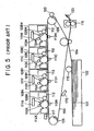
- FIG. 1 The embodiments shown in and discussed with respect to FIG. 1 do not from part of the present invention but represent background art that is useful for understanding the invention.
- Fig. 1 schematically shows the structure of an image forming apparatus in accordance with the present embodiment.
- Image forming stations 8M, 8C, 8Y, and 8K are juxtaposed in a manner corresponding to the direction of movement of a transfer/transport belt 7 serving as a transfer medium bearing member.
- Part of each image forming station (including at least a photosensitive drum and a cleaning unit) is attachable or detachable to or from a main unit of the image forming apparatus in the form of a process cartridge.
- a photosensitive drum 9M serving as an image bearing member is included in the image forming station 8M.
- a primary electrification roller 10M, an exposure unit 11M, a developer 12M, and a cleaning unit (including a cleaning blade and a waste toner container) 14M are arranged within the image forming station 8M in an operational order corresponding to the direction of rotation in which the photosensitive drum 9M rotates.
- a photosensitive drum, a primary electrification roller, an exposure unit, a developer, and a cleaning unit are included.
- the transfer/transport belt 7 is laid over a drive roller 5 and a driven roller 6.
- the drive roller 5 is driven to rotate by a drive motor (for example, a stepper motor) that is not shown.
- the rotational driving force propagates from the drive roller 5 to the transfer/transport belt 7.
- the direction of movement of the photosensitive drums 9M, 9C, 9Y, 9K located at respective transfer positions is substantially identical to the direction of movement of the transfer/transport belt 7.
- the transfer/transport belt 7 and the photosensitive drums 9M to 9K start rotating. At this time, the transfer/transport belt 7 comes into contact with the photosensitive drums 9M to 9K.
- the surface of the photosensitive drum 9M is electrified to assume a desired potential using the primary electrification roller 10M (a negative potential in the present embodiment).
- the electrified surface of the photosensitive drum 9M is exposed based on image information by means of the exposure unit 11M, whereby an electrostatic latent image is formed.
- the electrostatic latent image formed on the photosensitive drum 9M is developed with a magenta toner (toner characteristic of being negatively electrified) by means of the developer 12M.
- a magenta toner image is then formed on the photosensitive drum 9M.
- the magenta toner image is transferred to a transfer medium 1, which is borne by the transfer/transport belt 7 and fed according to the timing of the magenta toner image, by means of a transfer roller 13M serving as a transferring means.
- a predetermined voltage positive voltage in the present embodiment
- a cyan toner image, a yellow toner image, and a black toner image formed on the photosensitive drums 9C to 9K are successively transferred onto a transfer medium 1 as it is transported by the transfer/transport belt 7, and superimposed on one another. Thereafter, the transfer medium 1 is separated from the transfer/transport belt 7.
- the toner images are heated, pressured, and fixed onto the transfer medium 1 by means of a fixer 15.
- the transfer medium 1 having the images fixed thereto is then ejected out from the image forming apparatus. Thus, the image formation process is completed.
- the density of toner in a toner image formed on a photosensitive drum may vary as a function of time and/or depending on the temperature or humidity in the apparatus.
- a density detection toner image 18 is formed with toner of a predetermined density on each of the photosensitive drums, and transferred onto the transfer/transport belt 7.
- the density of toner in the density detection toner image 18 is then checked using an optical density sensor 17.
- An electric signal proportional to the density detected by the optical density sensor 17 is sent to a control unit (CPU 50).
- the control unit controls an amount of toner to be fed to the corresponding developer 12. This density control sequence is carried out for each image forming station.
- color toner images may be improperly superimposed on one another on the transfer member; in other words, the color toner images may be mismatched. This is attributable to an error in dimensions occurring during assembling of components, replacement of a transfer/transport belt unit including the transfer/transport belt 7, or replacement of a process cartridge.
- a color mismatch control sequence may be carried out at intervals of a predetermined period or according to predetermined timing.
- a predetermined toner image intended to control a color mismatch is formed on each photosensitive drum, and transferred onto the transfer/transport belt 7.
- the sensor 17 e.g., a charge-coupled device (CCD) or the like
- CCD charge-coupled device
- unnecessary toner on the transfer/transport belt 7 is electrostatically transferred onto the photosensitive drums 9.
- the inversely transferred unnecessary toner is collected into the cleaning units 14 associated with the respective photosensitive drums 9.
- the performance of toner may greatly vary as a function of time or depending on the temperature or humidity in the apparatus. Namely, with the passage of time, the diameter of particles of toner decreases or the liability to electrification thereof deteriorates. Consequently, the toner becomes unsusceptible to an electric field. This may invite degradation of cleaning efficiency and cause imperfect cleaning. Moreover, when a paper jam occurs or when the density detection toner image or color mismatch control toner image is transferred onto the transfer/transport belt 7, the amount of toner is much larger than a normal amount of toner, thereby causing a stain. The transfer/transport belt 7 must be rotated many turns in order to complete the cycle of transferring toner from the transfer/transport belt 7 to each photosensitive drum 9 and collecting it into each waste toner container. This is time-consuming. Additionally, deterioration of one or more components may occur (for example, the service lives of the photosensitive drum and transfer/transport belt may be shortened).
- unnecessary toner adhering to the transfer/transport belt 7 consists of toners 19 of positive and negative polarities.
- the respective polarities of the voltages to be applied to transfer rollers 13M, 13C, 13Y, and 13K are reversed appropriately, and toner is transferred to the photosensitive drums 9M, 9C, 9Y, and 9K. Cleaning is thus achieved.
- a voltage of positive polarity is applied to the transfer rollers 13M and 13K
- a voltage of negative polarity is applied to the transfer rollers 13C and 13Y.
- Toner electrified mainly positively is transferred onto the photosensitive drums 9M and 9K
- toner electrified mainly negatively is transferred onto the photosensitive drums 9C and 9Y.
- a voltage of 1.0 kV whose polarity (positive polarity in the present embodiment) is the same as that of a voltage to be applied for ordinary image formation is applied to the transfer roller 13M.
- Toner whose polarity has become opposite to the polarity exhibited by normally electrified toner is transferred onto the photosensitive drum 9M and collected into the waste toner container included in the cleaning unit 14M. At this time, toner not transferred onto the photosensitive drum 9M but passed through it may contain toner whose polarity has been reversed.
- the polarity of a voltage to be applied to the transfer roller 13M is made opposite to the polarity exhibited by normally electrified toner.
- toner remaining on the transfer/transport belt 7 consists of negative toner that has not been collected and toner that is electrified to exhibit polarity (positive polarity) opposite to the polarity exhibited by normally electrified toner while passing through the photosensitive drum 9C and transfer roller 13C.
- a voltage of -1.5 kV whose polarity is opposite to that of a voltage to be applied for ordinary image formation (positive polarity in the present embodiment) is applied to the transfer roller 13Y.
- Negatively electrified toner that has not been collected using the photosensitive drum 9C is transferred onto the photosensitive drum 9Y and collected into the waste toner container included in the cleaning unit 14Y. Unnecessary negatively electrified toner on the transfer/transport belt is nearly entirely collected. Thereafter, only a small amount of positively electrified toner remains on the transfer/transport belt 7.
- a voltage of 1.0 kV whose polarity is the same as that of a voltage to be applied for ordinary image formation (positive polarity in the present embodiment) is applied to the transfer roller 13K.
- Toner exhibiting (positive) polarity opposite to the polarity exhibited by normally electrified toner, which has not been transferred onto the photosensitive drums 9M, 9C, and 9Y but has remained on the transfer/transport belt 7, is transferred onto the photosensitive drum 9K and collected into the waste toner container included in the cleaning unit 14K.
- the removal of unnecessary toner so as to clean the transfer/transport belt 7 is complete.
- a peripheral speed of the transfer/transport belt 7 passing through each transfer position and that of the corresponding photosensitive drum 9 passing through the transfer position do not fully equate with each other because of the uncertainty in mechanical precision of each component.
- the transfer position is a position at which each photosensitive drum and the transfer/transport belt come into contact with each other with the transfer medium between them.
- the peripheral speed of the transfer/transport belt 7 passing through the respective transfer positions and the peripheral speed of each of the photosensitive drums 9M to 9K should be somewhat different from each other. This would prevent the phenomenon of a transferred toner image having a blank in the center thereof, or would ensure a safe transporting speed at which the transfer/transport belt 7 transports the transfer medium.
- the ratio of the difference between the peripheral speed (A) of the photosensitive drum and the peripheral speed (B) of the transfer/transport belt to the peripheral speed (A), (B-A)+A ⁇ 100 (%), should preferably be equal to or less than 3%.
- the difference in peripheral speed between the photosensitive drum and the transfer/transport belt may not always be preserved but may be nil.
- the difference between the peripheral speed of the transfer/transport belt 7 and the peripheral speed of the photosensitive drums 9M, 9C, 9Y, and 9K is set to a larger value for cleaning than the value for ordinary image formation.
- the peripheral speed of the transfer/transport belt 7 is higher than that set for ordinary image formation. Because of this constituent feature, toner on the transfer/transport belt 7 for which liability to electrification has deteriorated or a density detection toner image or color mismatch control toner image that has layered or transferred on or onto the transfer/transport belt 7 because of a paper jam can be efficiently transferred onto the photosensitive drum 9M, 9C, 9Y, and 9K in a short period of time. In short, transfer efficiency can be improved, and cleaning efficiency can be improved.
- Fig. 3 shows the relationship between the foregoing ratio and the density of toner remaining on the transfer/transport belt 7 after the aforesaid cleaning sequence is carried out by rotating: the transfer/transport belt 7 one turn.
- a border line 60 drawn in Fig. 3 indicates a threshold. When the density of toner remaining on the transfer/transport belt 7 falls below the threshold, the toner density is negligible in practice. This means that cleaning has been achieved properly.
- the aforesaid ratio should preferably be set to at least 6%.
- the ratio should preferably be set to 10% or more.
- the aforesaid ratio should preferably be set to 200% or less.
- the peripheral speeds of the transfer/transport belt 7 and photosensitive drum 9 vary greatly between ordinary image formation and cleaning.
- the cleaning sequence is therefore carried out during a period from the instant the ordinary image formation is completed to the instant the image formation start signal is applied next, that is, during a so-called after-rotation.
- the transfer/transport belt 7 may be cleaned at any time.
- the apparatus is brought to a state of waiting for next application of the image formation start signal, that is, a so-called standby mode.
- drive sources M1 to M4 for rotating the photosensitive drums are included separately from a drive source M5 for rotating the transfer/transport belt.
- the peripheral speed of the photosensitive drum 9 is set to a different value from that of the transfer/transport belt 7.
- Toner on the transfer/transport belt 7 is forcibly agitated using a frictional force, whereby the effect of a van der Waals force between the transfer/transport belt 7 and the toner is weakened.
- the toner has nonpolar toner thereof reduced with application of charge by the transfer roller 13. Consequently, the toner becomes susceptible to an electric field.
- cleaning efficiency improves drastically. Cleaning can therefore be achieved highly efficiently on a stable basis in a short period of time.
- the transfer roller 13 is employed as a transferring means.
- a blade, a brush, or a corona electrifier that is a noncontact electrifier may be employed.
- a contact electrifier such as a roller, blade, or brush should be adopted as the transferring means.
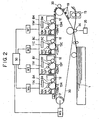
- Fig. 2 schematically shows the structure of an image forming apparatus having an intermediate transfer belt 30 as an intermediate transfer member.
- the present invention can be applied not only to the image forming apparatus of the first embodiment but also to the image forming apparatus shown in Fig. 2 .
- the same reference numerals will be assigned to members having the same abilities as those shown in Fig. 1 , and the description of those members will be omitted.
- An image formation process will be briefly described below.
- an image formation start signal is applied the intermediate transfer belt 30 and the photosensitive drums 9M to 9K start rotating.
- the intermediate transfer belt 30 comes into contact with the photosensitive drums 9M to 9K.
- the surface of the photosensitive drum 9M is electrified to a desired potential using the primary electrification roller 10M (negative potential in the present embodiment).
- the electrified surface of the photosensitive drum 9M is exposed based on image information by means of the exposure unit 11M, and an electrostatic latent image is formed on the photosensitive drum 9M.
- the electrostatic latent image formed on the photosensitive drum 9M is developed with a magenta toner (toner characteristic of being negatively electrified) by means of the developer 12M, whereby a magenta toner image is formed on the photosensitive drum 9M.
- the magenta toner image is electrostatically transferred to the intermediate transfer belt 30 by means of the primary transfer roller 13M.
- a predetermined voltage positive voltage in the present embodiment
- a cyan toner image, a yellow toner image, and a black toner image formed on the photosensitive drums 9C to 9K respectively are first transferred successively onto the intermediate transfer belt 30 and superimposed on one another. Thereafter, the plurality of color toner images on the intermediate transfer belt 30 are secondly transferred all together onto the transfer medium 1, which is fed according to predetermined timing, by means of a secondary transfer roller 34. At this time, a predetermined voltage (positive voltage in the present embodiment) is applied from a power supply 35 to the secondary transfer roller 34. Thereafter, the transfer medium 1 is transported to the fixer 15. The toner images are heated, pressured, and fixed onto the transfer medium 1 by means of the fixer 15. The transfer medium 1 having the toner images fixed thereto is then ejected out from the image forming apparatus. The image formation process is thus completed.
- the intermediate transfer belt 30 can be cleaned while having unnecessary toner removed therefrom.
- the present embodiment is nearly identical to the second embodiment.
- a difference lies in that an electrification roller 20 is included for electrifying unnecessary toner on the intermediate transfer belt 30 shown in Fig. 2 so that the toner will exhibit polarity (positive polarity in the present embodiment) opposite to the polarity exhibited by normally electrified toner.
- the cleaning sequence for cleaning the intermediate transfer belt 30 employed in the second embodiment is carried out at any time during a period from the instant ordinary image formation is completed to the instant the image formation start signal is applied next, that is, during a so-called after-rotation. When either the aforesaid density control sequence or color mismatch control sequence may be carried out, after the sequence is completed, the cleaning sequence may be carried out at any time.
- toner adhering to a portion of the photosensitive drum 9 not engaged in image formation may adhere, to a portion of the intermediate transfer belt 30 between the trailing edge of a toner image transferred from the photosensitive drum 9 thereto and the leading edge of the next toner image (hereinafter referred to as an inter-toner image portion). According to the object of the present embodiment such unnecessary toner is to be removed.
- a second cleaning sequence is added in order to remove toner adhering to the inter-toner image portion of the intermediate transfer belt 30.
- the second cleaning sequence includes a primary transfer step. Unlike the first cleaning sequence, the difference in peripheral speed between the photosensitive drum 9 and intermediate transfer belt 30 cannot be made large. However, since only a small amount of toner adheres to the inter-toner image portion of the intermediate transfer belt 30, the difference in peripheral speed may be identical to the difference, in peripheral speed attained for ordinary image formation.
- the intermediate transfer belt 30 employed in the present embodiment is a seamless belt. No limitations are therefore imposed on a position on the intermediate transfer belt at which a toner image should be transferred.
- the respective polarities of the voltages to be applied to the primary transfer rollers 13M to 13K are opposite to those of the voltages employed in the first embodiment. This is intended to prevent the collection of a majority of unnecessary toner from the intermediate transfer belt 30 into the cleaning unit 14M. Because of this constituent feature, the replacement interval for the image forming station 8M (process cartridge) will be commensurate with that of each of the other image forming stations.
- the first cleaning sequence is carried out in order to remove unnecessary toner from the intermediate transfer belt 30.
- the second cleaning sequence is carried out in order to remove unnecessary toner from the intermediate transfer belt 30.
- the CPU 50 selects either of the first and second cleaning sequences. Therefore, for example, if images are formed consecutively on one hundred transfer media, no disordered images will be produced. A high-quality image can be produced every time.
- the CPU selects either of the first and second cleaning sequences, abrasion of the surfaces of the photosensitive drum and intermediate transfer belt can be suppressed. Consequently, the durability of the apparatus can be improved.
- the polarity of a voltage to be applied to the transfer rollers 13M and 13K is the same as the polarity exhibited by normally electrified toner.
- the polarity of a voltage to be applied to the transfer rollers 13C and 13Y is opposite to the polarity exhibited by normally electrified toner.
- unnecessary toner on the transfer/transport belt 7 is transferred onto the photosensitive drum 9.
- the present invention is not limited to this mode.
- the combination of polarities of voltages to be applied to the primary transfer rollers 13M to 13K is not limited to the one employed in the third embodiment. Namely, any combination will do as long as a voltage of positive polarity is applied to at least one of the (primary) transfer rollers 13M to 13K, and a voltage of negative polarity is applied to at least one of the other transfer rollers.
- the peripheral speed of the intermediate transfer belt 30 is set higher than that of the photosensitive drum 9. This is intended to improve cleaning efficiency, shorten the time required to collect unnecessary toner, and stabilize the peripheral speed of either the transfer/transport belt 7 or the intermediate transfer belt 30.
- the peripheral speed of either the transfer/transport belt 7 or intermediate transfer belt 30 may be set lower than that of the photosensitive drum 9.
- the direction of movement in which the transfer/transport belt 7 or intermediate transfer belt 30 passes through each transfer position is substantially identical to the direction of movement of the photosensitive drum.
- the ratio of the difference in peripheral speed between the photosensitive drum 9 and transfer/transport belt 7 (intermediate transfer belt 30) to the peripheral speed of the photosensitive drum 9 should preferably be -6% or less. More preferably, the ratio should be -10% or less.
- the control unit causes the transfer/transport belt 7 or intermediate transfer belt 30 to rotate slower than the photosensitive drum 9. Assuming that the unnecessary toner collection time is restricted to some value, the transfer/transport belt 7 or intermediate transfer belt 30 is rotated more quickly than the photosensitive drum 9. Thus, the control unit switches the rotating speeds at which the transfer/transport belt or intermediate transfer belt is rotated. Cleaning is therefore carried out optimally according to any situation.
- the normal polarity exhibited by normally electrified toner is defined as negative polarity.
- the voltage to be applied to each of the (primary) transfer rollers 13M to 13K is either +1.0 kV or -1.5 kV.
- the present invention is not limited to the negative polarity and the voltages of +1.0 kV or -1.5 kV.
- the peripheral speed of the photosensitive drum 9, transfer/transport belt 7, or intermediate transfer belt 30 is set to one specific value for ordinary image formation.
- the peripheral speed of the photosensitive drum 9, transfer/transport belt 7, or intermediate transfer belt 30 to be set for image formation may be varied depending on the kind of transfer medium in consideration of the property thereof concerning fixation of toner.
- the peripheral speed to be set for image formation on a transparent resin medium used exclusively for an overhead projector (OHT) may be set to one-fourth of the peripheral speed to be set for image formation on, for example, plain paper.
- the peripheral speed to be set for image formation on cardboard may be set to one-third of the peripheral speed to be set for image formation on plain paper.
- the peripheral speed to be set for cleaning is higher than the peripheral speed to be set for image formation on plain paper.
- the transfer medium bearer and intermediate transfer member are shaped like a belt. Alternatively, they may be shaped - 30 - like a drum. Nevertheless, the present invention can be applied in the same manner.
- color toner images are successively transferred from the image bearers (photosensitive members) onto the transfer medium borne by the transfer medium bearer, and thus superimposed on one another.
- color toner images are successively transferred from the image bearers onto the intermediate transfer members, and thus superimposed on one another. Thereafter, the superimposed color toner images on the intermediate transfer member are transferred all together onto the transfer medium.
Landscapes
- Physics & Mathematics (AREA)
- General Physics & Mathematics (AREA)
- Electrostatic Charge, Transfer And Separation In Electrography (AREA)
- Control Or Security For Electrophotography (AREA)
- Color Electrophotography (AREA)
- Cleaning In Electrography (AREA)
Applications Claiming Priority (3)
| Application Number | Priority Date | Filing Date | Title |
|---|---|---|---|
| JP25296899 | 1999-09-07 | ||
| JP2000209753A JP3976990B2 (ja) | 1999-09-07 | 2000-07-11 | 画像形成装置 |
| EP00119512A EP1083465B1 (en) | 1999-09-07 | 2000-09-06 | Image forming apparatus with transfer means adapted for cleaning |
Related Parent Applications (2)
| Application Number | Title | Priority Date | Filing Date |
|---|---|---|---|
| EP00119512A Division EP1083465B1 (en) | 1999-09-07 | 2000-09-06 | Image forming apparatus with transfer means adapted for cleaning |
| EP00119512.2 Division | 2000-09-06 |
Publications (2)
| Publication Number | Publication Date |
|---|---|
| EP1942383A1 EP1942383A1 (en) | 2008-07-09 |
| EP1942383B1 true EP1942383B1 (en) | 2011-05-11 |
Family
ID=26540968
Family Applications (2)
| Application Number | Title | Priority Date | Filing Date |
|---|---|---|---|
| EP08153374A Expired - Lifetime EP1942383B1 (en) | 1999-09-07 | 2000-09-06 | Self-cleaning image forming apparatus |
| EP00119512A Expired - Lifetime EP1083465B1 (en) | 1999-09-07 | 2000-09-06 | Image forming apparatus with transfer means adapted for cleaning |
Family Applications After (1)
| Application Number | Title | Priority Date | Filing Date |
|---|---|---|---|
| EP00119512A Expired - Lifetime EP1083465B1 (en) | 1999-09-07 | 2000-09-06 | Image forming apparatus with transfer means adapted for cleaning |
Country Status (4)
| Country | Link |
|---|---|
| US (1) | US6385428B1 (enExample) |
| EP (2) | EP1942383B1 (enExample) |
| JP (1) | JP3976990B2 (enExample) |
| DE (1) | DE60039664D1 (enExample) |
Families Citing this family (22)
| Publication number | Priority date | Publication date | Assignee | Title |
|---|---|---|---|---|
| JP4375699B2 (ja) * | 2000-09-14 | 2009-12-02 | 株式会社リコー | タンデム作像装置およびそれを備える画像形成装置、ならびに作像手段の配置方法 |
| US6836641B2 (en) * | 2002-02-18 | 2004-12-28 | Canon Kabushiki Kaisha | Image forming apparatus and image forming method |
| US6952548B2 (en) * | 2002-05-31 | 2005-10-04 | Canon Kabushiki Kaisha | Charging apparatus with auxiliary member and image forming apparatus having the charging apparatus |
| US6860665B2 (en) * | 2002-10-28 | 2005-03-01 | Hewlett-Packard Development Company, L.P. | Passive linear encoder |
| JP2004151125A (ja) * | 2002-10-28 | 2004-05-27 | Canon Inc | 定着装置 |
| US7010256B2 (en) * | 2002-11-14 | 2006-03-07 | Canon Kabushiki Kaisha | Image heating apparatus having recording medium conveying nip nonuniform in pressure distribution |
| JP2004252172A (ja) * | 2003-02-20 | 2004-09-09 | Canon Inc | 画像形成装置 |
| JP2004279474A (ja) | 2003-03-12 | 2004-10-07 | Brother Ind Ltd | 画像形成装置 |
| US7123869B2 (en) * | 2003-08-28 | 2006-10-17 | Kyocera Mita Corporation | Color image forming method and apparatus with image flaw reducing speed control of toner image carrier peripheral velocity |
| JP4763988B2 (ja) * | 2004-02-17 | 2011-08-31 | キヤノン株式会社 | 画像形成装置 |
| US7206523B2 (en) * | 2004-09-13 | 2007-04-17 | Kabushiki Kaisha Toshiba | Color image forming apparatus and method using detachable process units |
| JP4936702B2 (ja) * | 2005-03-14 | 2012-05-23 | 株式会社リコー | 画像形成装置 |
| JP4490903B2 (ja) * | 2005-11-01 | 2010-06-30 | 株式会社リコー | 画像形成装置 |
| KR100667828B1 (ko) * | 2005-11-03 | 2007-01-11 | 삼성전자주식회사 | 화상전사유닛, 이를 구비한 전자사진방식 화상형성장치 및,전자사진방식 화상형성방법 |
| US7860420B2 (en) * | 2005-12-05 | 2010-12-28 | Canon Kabushiki Kaisha | Cleaner-less image forming apparatus |
| JP2008191514A (ja) | 2007-02-06 | 2008-08-21 | Canon Inc | 画像形成装置 |
| US7890035B2 (en) * | 2007-12-10 | 2011-02-15 | Avision Inc. | Image forming apparatus and image transferring method therefor |
| JP2009276370A (ja) * | 2008-05-12 | 2009-11-26 | Konica Minolta Business Technologies Inc | 画像形成装置 |
| JP2012133399A (ja) * | 2012-04-09 | 2012-07-12 | Canon Inc | 画像形成装置 |
| JP6150620B2 (ja) * | 2012-06-13 | 2017-06-21 | キヤノン株式会社 | 画像形成装置 |
| JP5404884B2 (ja) * | 2012-10-01 | 2014-02-05 | キヤノン株式会社 | 画像形成装置 |
| JP5950874B2 (ja) * | 2013-07-02 | 2016-07-13 | キヤノン株式会社 | 画像形成装置 |
Family Cites Families (13)
| Publication number | Priority date | Publication date | Assignee | Title |
|---|---|---|---|---|
| US5179397A (en) | 1989-04-03 | 1993-01-12 | Canon Kabushiki Kaisha | Image forming apparatus with constant voltage and constant current control |
| EP0442527B1 (en) | 1990-02-16 | 1998-11-25 | Canon Kabushiki Kaisha | An image forming apparatus |
| JPH04208971A (ja) | 1990-12-03 | 1992-07-30 | Canon Inc | 画像形成装置 |
| US5438398A (en) * | 1992-05-29 | 1995-08-01 | Canon Kabushiki Kaisha | Image forming apparatus with intermediate transfer member |
| JPH0777879A (ja) * | 1993-09-07 | 1995-03-20 | Canon Inc | 画像形成装置 |
| JPH08328403A (ja) * | 1995-03-31 | 1996-12-13 | Ricoh Co Ltd | 画像形成装置 |
| JP3364553B2 (ja) * | 1995-04-03 | 2003-01-08 | 株式会社リコー | 画像形成装置 |
| DE69625542T2 (de) * | 1995-05-23 | 2003-10-02 | Canon K.K., Tokio/Tokyo | Bilderzeugungsgerät und Methode mit einem Zwischenübertragungselement |
| JP3423533B2 (ja) * | 1995-07-17 | 2003-07-07 | キヤノン株式会社 | 画像形成装置 |
| DE69629272T2 (de) | 1995-12-21 | 2004-04-22 | Canon K.K. | Bildtragendes Band und dieses verwendendes Bilderzeugungsgerät |
| JP3445122B2 (ja) | 1996-11-06 | 2003-09-08 | キヤノン株式会社 | 画像形成装置 |
| JP3937543B2 (ja) | 1997-12-26 | 2007-06-27 | キヤノン株式会社 | 画像形成装置 |
| JP3839979B2 (ja) * | 1998-11-18 | 2006-11-01 | キヤノン株式会社 | 画像形成装置 |
-
2000
- 2000-07-11 JP JP2000209753A patent/JP3976990B2/ja not_active Expired - Fee Related
- 2000-09-06 EP EP08153374A patent/EP1942383B1/en not_active Expired - Lifetime
- 2000-09-06 DE DE60039664T patent/DE60039664D1/de not_active Expired - Lifetime
- 2000-09-06 US US09/656,476 patent/US6385428B1/en not_active Expired - Lifetime
- 2000-09-06 EP EP00119512A patent/EP1083465B1/en not_active Expired - Lifetime
Also Published As
| Publication number | Publication date |
|---|---|
| EP1083465A3 (en) | 2004-03-31 |
| JP2001147632A (ja) | 2001-05-29 |
| JP3976990B2 (ja) | 2007-09-19 |
| EP1083465A2 (en) | 2001-03-14 |
| DE60039664D1 (de) | 2008-09-11 |
| EP1083465B1 (en) | 2008-07-30 |
| EP1942383A1 (en) | 2008-07-09 |
| US6385428B1 (en) | 2002-05-07 |
Similar Documents
| Publication | Publication Date | Title |
|---|---|---|
| EP1942383B1 (en) | Self-cleaning image forming apparatus | |
| US5765087A (en) | Color image forming method and color image forming apparatus practicable therewith | |
| US5079597A (en) | Cleaning method and apparatus for intermediate transfer member | |
| EP1262840B1 (en) | Image forming apparatus including discharging device for preventing reattachment of residual toner to intermediate transfer element | |
| US6879801B2 (en) | Image forming apparatus | |
| US6535707B2 (en) | Image forming system | |
| JP2011133581A (ja) | 画像形成装置 | |
| JP3950908B2 (ja) | 画像形成装置 | |
| US7627269B2 (en) | Image forming apparatus with charging member cleaning capabilities | |
| CN100492218C (zh) | 成像设备 | |
| JP4557379B2 (ja) | 画像形成装置 | |
| JP2003330289A (ja) | 画像形成装置 | |
| JP3793696B2 (ja) | 画像形成装置 | |
| JP2003140477A (ja) | 画像形成装置 | |
| JP4089204B2 (ja) | 画像形成装置 | |
| JP3877258B2 (ja) | 画像形成装置 | |
| JP7412677B2 (ja) | 帯電装置、プロセスカートリッジ、及び、画像形成装置 | |
| JP4455133B2 (ja) | 画像形成装置 | |
| JP4054568B2 (ja) | 画像形成装置 | |
| JPH07210011A (ja) | 画像形成装置 | |
| JP4472323B2 (ja) | 画像形成装置 | |
| JP7140553B2 (ja) | 画像形成装置 | |
| JP3658583B2 (ja) | カラー画像形成装置およびカラー画像形成方法 | |
| JP2005017424A (ja) | 画像形成装置 | |
| JP2003186364A (ja) | 画像形成装置 |
Legal Events
| Date | Code | Title | Description |
|---|---|---|---|
| PUAI | Public reference made under article 153(3) epc to a published international application that has entered the european phase |
Free format text: ORIGINAL CODE: 0009012 |
|
| AC | Divisional application: reference to earlier application |
Ref document number: 1083465 Country of ref document: EP Kind code of ref document: P |
|
| AK | Designated contracting states |
Kind code of ref document: A1 Designated state(s): DE FR GB IT |
|
| 17P | Request for examination filed |
Effective date: 20090109 |
|
| AKX | Designation fees paid |
Designated state(s): DE FR GB IT |
|
| GRAP | Despatch of communication of intention to grant a patent |
Free format text: ORIGINAL CODE: EPIDOSNIGR1 |
|
| GRAS | Grant fee paid |
Free format text: ORIGINAL CODE: EPIDOSNIGR3 |
|
| GRAA | (expected) grant |
Free format text: ORIGINAL CODE: 0009210 |
|
| AC | Divisional application: reference to earlier application |
Ref document number: 1083465 Country of ref document: EP Kind code of ref document: P |
|
| AK | Designated contracting states |
Kind code of ref document: B1 Designated state(s): DE FR GB IT |
|
| REG | Reference to a national code |
Ref country code: GB Ref legal event code: FG4D |
|
| REG | Reference to a national code |
Ref country code: DE Ref legal event code: R096 Ref document number: 60045966 Country of ref document: DE Effective date: 20110622 |
|
| PLBE | No opposition filed within time limit |
Free format text: ORIGINAL CODE: 0009261 |
|
| STAA | Information on the status of an ep patent application or granted ep patent |
Free format text: STATUS: NO OPPOSITION FILED WITHIN TIME LIMIT |
|
| 26N | No opposition filed |
Effective date: 20120214 |
|
| REG | Reference to a national code |
Ref country code: DE Ref legal event code: R097 Ref document number: 60045966 Country of ref document: DE Effective date: 20120214 |
|
| PGFP | Annual fee paid to national office [announced via postgrant information from national office to epo] |
Ref country code: IT Payment date: 20130903 Year of fee payment: 14 |
|
| PGFP | Annual fee paid to national office [announced via postgrant information from national office to epo] |
Ref country code: FR Payment date: 20130926 Year of fee payment: 14 |
|
| REG | Reference to a national code |
Ref country code: FR Ref legal event code: ST Effective date: 20150529 |
|
| PG25 | Lapsed in a contracting state [announced via postgrant information from national office to epo] |
Ref country code: IT Free format text: LAPSE BECAUSE OF NON-PAYMENT OF DUE FEES Effective date: 20140906 Ref country code: FR Free format text: LAPSE BECAUSE OF NON-PAYMENT OF DUE FEES Effective date: 20140930 |
|
| PGFP | Annual fee paid to national office [announced via postgrant information from national office to epo] |
Ref country code: DE Payment date: 20150930 Year of fee payment: 16 Ref country code: GB Payment date: 20150922 Year of fee payment: 16 |
|
| REG | Reference to a national code |
Ref country code: DE Ref legal event code: R119 Ref document number: 60045966 Country of ref document: DE |
|
| GBPC | Gb: european patent ceased through non-payment of renewal fee |
Effective date: 20160906 |
|
| PG25 | Lapsed in a contracting state [announced via postgrant information from national office to epo] |
Ref country code: GB Free format text: LAPSE BECAUSE OF NON-PAYMENT OF DUE FEES Effective date: 20160906 Ref country code: DE Free format text: LAPSE BECAUSE OF NON-PAYMENT OF DUE FEES Effective date: 20170401 |