EP1939639B1 - System and method for locating faults in a multi-ended power transmission line - Google Patents
System and method for locating faults in a multi-ended power transmission line Download PDFInfo
- Publication number
- EP1939639B1 EP1939639B1 EP07123293.8A EP07123293A EP1939639B1 EP 1939639 B1 EP1939639 B1 EP 1939639B1 EP 07123293 A EP07123293 A EP 07123293A EP 1939639 B1 EP1939639 B1 EP 1939639B1
- Authority
- EP
- European Patent Office
- Prior art keywords
- fault
- voltage
- current
- line
- composite
- Prior art date
- Legal status (The legal status is an assumption and is not a legal conclusion. Google has not performed a legal analysis and makes no representation as to the accuracy of the status listed.)
- Active
Links
Images


Classifications
-
- G—PHYSICS
- G01—MEASURING; TESTING
- G01R—MEASURING ELECTRIC VARIABLES; MEASURING MAGNETIC VARIABLES
- G01R29/00—Arrangements for measuring or indicating electric quantities not covered by groups G01R19/00 - G01R27/00
- G01R29/18—Indicating phase sequence; Indicating synchronism
-
- G—PHYSICS
- G01—MEASURING; TESTING
- G01R—MEASURING ELECTRIC VARIABLES; MEASURING MAGNETIC VARIABLES
- G01R31/00—Arrangements for testing electric properties; Arrangements for locating electric faults; Arrangements for electrical testing characterised by what is being tested not provided for elsewhere
- G01R31/08—Locating faults in cables, transmission lines, or networks
-
- G—PHYSICS
- G01—MEASURING; TESTING
- G01R—MEASURING ELECTRIC VARIABLES; MEASURING MAGNETIC VARIABLES
- G01R27/00—Arrangements for measuring resistance, reactance, impedance, or electric characteristics derived therefrom
- G01R27/02—Measuring real or complex resistance, reactance, impedance, or other two-pole characteristics derived therefrom, e.g. time constant
- G01R27/16—Measuring impedance of element or network through which a current is passing from another source, e.g. cable, power line
- G01R27/18—Measuring resistance to earth, i.e. line to ground
-
- G—PHYSICS
- G01—MEASURING; TESTING
- G01R—MEASURING ELECTRIC VARIABLES; MEASURING MAGNETIC VARIABLES
- G01R31/00—Arrangements for testing electric properties; Arrangements for locating electric faults; Arrangements for electrical testing characterised by what is being tested not provided for elsewhere
- G01R31/08—Locating faults in cables, transmission lines, or networks
- G01R31/081—Locating faults in cables, transmission lines, or networks according to type of conductors
- G01R31/086—Locating faults in cables, transmission lines, or networks according to type of conductors in power transmission or distribution networks, i.e. with interconnected conductors
-
- Y—GENERAL TAGGING OF NEW TECHNOLOGICAL DEVELOPMENTS; GENERAL TAGGING OF CROSS-SECTIONAL TECHNOLOGIES SPANNING OVER SEVERAL SECTIONS OF THE IPC; TECHNICAL SUBJECTS COVERED BY FORMER USPC CROSS-REFERENCE ART COLLECTIONS [XRACs] AND DIGESTS
- Y02—TECHNOLOGIES OR APPLICATIONS FOR MITIGATION OR ADAPTATION AGAINST CLIMATE CHANGE
- Y02E—REDUCTION OF GREENHOUSE GAS [GHG] EMISSIONS, RELATED TO ENERGY GENERATION, TRANSMISSION OR DISTRIBUTION
- Y02E40/00—Technologies for an efficient electrical power generation, transmission or distribution
- Y02E40/70—Smart grids as climate change mitigation technology in the energy generation sector
-
- Y—GENERAL TAGGING OF NEW TECHNOLOGICAL DEVELOPMENTS; GENERAL TAGGING OF CROSS-SECTIONAL TECHNOLOGIES SPANNING OVER SEVERAL SECTIONS OF THE IPC; TECHNICAL SUBJECTS COVERED BY FORMER USPC CROSS-REFERENCE ART COLLECTIONS [XRACs] AND DIGESTS
- Y02—TECHNOLOGIES OR APPLICATIONS FOR MITIGATION OR ADAPTATION AGAINST CLIMATE CHANGE
- Y02E—REDUCTION OF GREENHOUSE GAS [GHG] EMISSIONS, RELATED TO ENERGY GENERATION, TRANSMISSION OR DISTRIBUTION
- Y02E60/00—Enabling technologies; Technologies with a potential or indirect contribution to GHG emissions mitigation
-
- Y—GENERAL TAGGING OF NEW TECHNOLOGICAL DEVELOPMENTS; GENERAL TAGGING OF CROSS-SECTIONAL TECHNOLOGIES SPANNING OVER SEVERAL SECTIONS OF THE IPC; TECHNICAL SUBJECTS COVERED BY FORMER USPC CROSS-REFERENCE ART COLLECTIONS [XRACs] AND DIGESTS
- Y04—INFORMATION OR COMMUNICATION TECHNOLOGIES HAVING AN IMPACT ON OTHER TECHNOLOGY AREAS
- Y04S—SYSTEMS INTEGRATING TECHNOLOGIES RELATED TO POWER NETWORK OPERATION, COMMUNICATION OR INFORMATION TECHNOLOGIES FOR IMPROVING THE ELECTRICAL POWER GENERATION, TRANSMISSION, DISTRIBUTION, MANAGEMENT OR USAGE, i.e. SMART GRIDS
- Y04S10/00—Systems supporting electrical power generation, transmission or distribution
- Y04S10/22—Flexible AC transmission systems [FACTS] or power factor or reactive power compensating or correcting units
-
- Y—GENERAL TAGGING OF NEW TECHNOLOGICAL DEVELOPMENTS; GENERAL TAGGING OF CROSS-SECTIONAL TECHNOLOGIES SPANNING OVER SEVERAL SECTIONS OF THE IPC; TECHNICAL SUBJECTS COVERED BY FORMER USPC CROSS-REFERENCE ART COLLECTIONS [XRACs] AND DIGESTS
- Y04—INFORMATION OR COMMUNICATION TECHNOLOGIES HAVING AN IMPACT ON OTHER TECHNOLOGY AREAS
- Y04S—SYSTEMS INTEGRATING TECHNOLOGIES RELATED TO POWER NETWORK OPERATION, COMMUNICATION OR INFORMATION TECHNOLOGIES FOR IMPROVING THE ELECTRICAL POWER GENERATION, TRANSMISSION, DISTRIBUTION, MANAGEMENT OR USAGE, i.e. SMART GRIDS
- Y04S10/00—Systems supporting electrical power generation, transmission or distribution
- Y04S10/50—Systems or methods supporting the power network operation or management, involving a certain degree of interaction with the load-side end user applications
- Y04S10/52—Outage or fault management, e.g. fault detection or location
Definitions
- the field of the invention relates generally to identification and location of faults in electrical power transmission lines.
- Fault location is commonly performed as an adjunct to the functioning of distance-based power system protective relays.
- the most common approaches use voltage and current measurements from a single line terminal to estimate the fault location using various assumptions and approximations. Such approaches are referred to as single-ended methods and are not very accurate. The lack of absolute accuracy is primarily a result of having more unknowns than equations that could be derived from the line and system model based on measurements from one end of the line. As a result assumptions are made.
- Various assumptions yield various single-ended fault location methods. When the assumptions are satisfied in a given fault situation, the fault location result is accurate. If the assumptions are not satisfied, an inherent, sometimes very significant, error of the method will occur.
- multi-ended fault locators Fault location systems that utilize information from more than one line terminals are referred to as multi-ended fault locators.
- a multi-ended fault locator eliminates the key weakness of a single-ended approach, but requires communication channels to rely data from geographically dispersed line terminals to a single location where the actual fault location calculations are performed. Some multi-ended fault location methods also require synchronization of the data between the line terminals. These two requirements make the multi-ended fault location methods difficult to implement.
- U.S. Patent 6,256,592 describes a multi-ended system for locating a fault on a power line using the magnitude value of the negative sequence current and the magnitude and angle values of the negative sequence impedance at the time the fault occurs.
- U.S. Patent 6,256,592 uses the negative sequence current information to produce results in near real time by reducing the amount of data that must be transmitted between terminals.
- U.S. Patent 6,879,917 uses positive- or negative-sequence currents and voltages to locate faults. Most fault types are covered by the negative-sequence method of the patent. Three-phase balanced faults do not produce any negative-sequence signals rendering the negative-sequence method of U.S. Patent 6,879,917 useless. Therefore the said patented method adds the positive-sequence based equations to eliminate this weakness. As a result, two sets of calculations must be run in parallel, or a coarse fault type identification must be performed.
- United States Patent No. 4275429 describes a pilot protective relay apparatus for high-voltage, three-phase alternating current transmission lines. The is completely solid state, making trip decisions based upon three separate comparisons of the near and far line current conditions represented by line current derived single-phase voltage signals. The three comparisons indicate the magnitude of the phasor difference, the magnitude of the phase angle, and the relative average absolute magnitudes.
- the need for fault type identification is a weakness for real-time systems with limited communication bandwidth.
- the remote portion of the locator needs to send both negative- and positive-sequence based signals, or the two portions of the locator must work flawlessly in terms of fault type identification. If one portion sends the negative-sequence based information, while the other portion combines it with the positive-sequence based information, significant errors in the fault distance estimate will occur.
- a typical single- or multi-ended fault locator requires knowledge of the fault type, i.e. which and how many conductors are involved in the fault, knowledge of the mutual coupling to adjacent lines located on the same towers or in close proximity, and some other auxiliary information. These extra factors are found through separate procedures, and if delivered to the main fault location procedure with errors, they will impact the overall fault location accuracy.
- multi-ended systems working in real or near-real time such as locators integrated with protection relays, it is important to limit the bandwidth requirements for communications, and in particular, the amount of information that needs to be sent between different terminals of the transmission line.
- the present invention resides in a fault position detection system and a method as recited in the appended claims.
- a fault position detection system in accordance with an embodiment of the invention utilizes synchronized phasor measurements of uniquely designed composite currents and voltages from all ends of a power transmission line and basic network equations.
- the system is applicable to transmission lines having two or more terminals.
- the method does not require the knowledge of the fault type, fault resistance, the amount of mutual coupling with adjacent lines, or the zero-sequence impedance of the given line.
- the capability of ignoring the last value makes the method very useful for application on cable lines where the zero-sequence impedance varies and is difficult to deal with.
- the fault impedance is estimated.
- the system is compensated for the effects of line charging currents.
- the fault detection system of various embodiments of the invention embodied herein is based on the idea that synchronized voltage and current measurements at all ends of the transmission line make it possible to use network equations directly to compute the fault location without assumptions or approximations, using the composite signals and associated network only.
- the composite signal is created in such a way that regardless of the fault type, there is a disturbance in the composite signals.
- the composite voltage at the fault can be computed from each end of the line by subtracting the line drop to the fault from the voltage at that end using the composite voltages at the terminals, composite currents and appropriate impedance.
- the systems and calculations for two-ended and three-ended systems are similar and will be described further herein, first in summary, and then with reference to the attached drawings.
- the two-ended system executes an algorithm on measurements separately on each terminal. Either result is sufficient to locate the fault. Both terminals will compute exactly the same fault location, since they use exactly the same equations applied to the same data. This could be summarized that the calculations are symmetrical in terms of identical equations executed at both ends of the line, and redundant in terms of the results remaining in the a priori known relationship. Thus, the two-ended system can compare the results of the calculations to ensure accuracy. In a further embodiment of the two-ended system, the system can be configured to subsequently calculate fault resistance at each terminal from the fault location plus local measurements, so that each terminal may compute a slightly different estimate. The two estimate values can be averaged to increase accuracy.
- the three-terminal system executes an algorithm at each terminal that has information from all three terminals. In the case where one communication channel is down, this may be only one of the three terminals.
- the system algorithm has two parts - one part that determines which line segment is faulted, and a second part that locates the fault on the faulted segment. As with the two-terminal system, the algorithm will calculate exactly the same fault location from each terminal. However, each terminal may report a slightly different fault resistance. The accuracy of the fault resistance calculation can be increased by averaging the determined value obtained from each terminal in a subsequent step.
- Fig. 1 illustrates a composite signal network 100 for a two-terminal power transmission line.
- the fault location algorithm of the system does not need to explicitly determine the composite voltage at the fault 150. Instead, it eliminates the fault voltage V(F) from the equations for fault location by using other information instead.
- the system algorithm is based upon the following fault measurements and settings:
- the composite signals must be defined first. These signals are selected with the objective to provide for non-zero operating quantity for any fault type (symmetrical, unbalanced, with ground or isolated from the ground) so that the fault type identification is not required prior to creating such composite operating signal. Another objective is to create the composite signal in such a way that the effect of currents flowing to the ground is eliminated. This is to increase accuracy with respect to mutual coupling effects with other lines. Yet another objective is to represent the situation with a single current and voltage so that minimum amount of data is exchanged between the parts of the fault location system placed at various terminals of the transmission line.
- This invention uses generalized Clarke transform to represent voltages and currents for the purpose of fault locating.
- alpha 0
- the generalized Clarke transform of this invention becomes the traditional Clarke transform.
- This invention claims a method in which a single signal is created to represent the three measured signals (A,B,C) for the fault location purposes, in such a way that the ground currents do not affect the said signal, and the said signal is non-zero for all fault types. Therefore equations (1) through (3) are just examples, and those skilled in the art can derive many alternatives of this approach.
- phase currents (IA,IB,IC) and voltages (VA,VB,VC) at all the points of interest are converted into the composite signal such as the generalized Clarke transform using the same transformation method throughout the network of interest. This conversion takes place in the apparatus that locates the faults, and is performed mathematically on all signals when deriving the fault location method and equations.
- the compensated phase current phasors are used when deriving the composite current signals, and will provide a fault location estimate that takes full advantage of the compensation. Effects of charging current are described further below.
- Equation (4) takes advantage of redundancy in the data. There are more equations than unknowns, so a least mean squares fit is used. The equation is independent of faulted phase, fault type, fault resistance, and zero-sequence (ground current) coupling to an adjacent transmission line, if any.
- Equation (4) can be computed at either or both first and second terminals 105, 110, producing exactly the same fault location estimate, except measured from opposite ends of the line. As one will recognize, the roles of the two terminals 105, 110 are exchanged when changing the terminal at which equation (1) is computed. The two F values should sum identically to 1.
- the error produced by equation (1) as a result of measurement and parameter error is equal to 1 ⁇ 2 of the worst relative sensor error, such as a CT type device error. That comes out to be 2.5-5% for typical CT and fault location instrumentation errors.
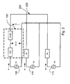
- the two-terminal algorithm described above is readily extended to a three-terminal system 200, such as shown in Fig. 2 .
- the situation for a three-terminal system 200 is illustrated for the case in which the fault 150 is on the line from the first terminal 105 to the tap 220.
- the situations for a fault 150 located on one of the other two line segments are not shown, but can be obtained by a cyclic permutation of line indices.
- VT(1), VT(2) and VT(3) are the tap voltages calculated from each of the first, second and third terminals 105, 110, 115, respectively.
- the line segment containing the fault 150 is determined.
- the determination of the line can be done by recognizing that the voltage drops around a loop through the unfaulted line segments will sum to zero. Residual voltage phasors are computed for each loop. The loop with the lowest residual voltage contains the two unfaulted line segments. In other words, only one line segment is faulted and the two unfaulted segments allow the two terminals to estimate the real tap voltage. As a result if a given pair of terminals determines the same tap voltage, the fault must be between the tap and the third terminal.
- R 2 1 VT 2 - VT 3 2
- R 2 2 VT 3 - VT 1 2
- R 2 3 VT 1 - VT 2 2
- the fault 150 is located using a formula derived for the two-terminal lines fed with data appropriate for that line segment. Each formula is obtained from any of the other formulae by a cyclic permutation of the indices N. The formulae for each index or line are given below.
- the factional fault location from the terminal end 105 of the line segment containing fault 150 is then computed from the terminal 105 and tap current and voltage phasors.
- Equation (8) can be implemented at any or all of the three terminals 105, 110, 115 that have the necessary information available. All three results will be identical. It should be noted that some care must be taken with the fact that the three terminals 105, 110, 115 have different indices within each terminal in a peer-to-peer architecture such as described in the embodiment of Fig. 2 . As will be appreciated, if all three communications channels are in operation, then all three terminals can compute the fault 150 location, whereas, if only two are in operation, then only one terminal 105, 110, 115 can perform the computation - the terminal 105, 110, 115 connected to both operational channels. If only one channel is operational, then faults cannot be detected or located using the system 200. As will be understood, all of the required measurements can be obtained and calculations can be made using conventional measuring and/or computing devices connected with or in communication with the transmission line circuit and communications paths and configured in accordance with the embodiments described herein.
- the fault resistance can be calculated by computing the phase to ground voltages at the fault 150 by starting at the terminal voltages and subtracting voltage drops to the known fault location 150.
- Fault resistance can be computed using the systems 100, 200 as well. Once the fault 150 is located, it is a simple matter to estimate the fault resistance. The details depend on the fault type and the number of terminals. The following explanation considers the two-terminal equations. The three terminal equations are similar, and one will understand how to obtain those equations from the two-terminal explanation below.
- the fault resistance is estimated by taking the real part of the ratio of the fault voltage and current phasors for the faulted phase.
- the voltage phasor is estimated by starting at the terminal end 105, 110, 115 where phase voltage phasors are known and subtracting the voltage drop at the fault 150.
- the possible effects of the mutual coupling from an adjacent line are considered.
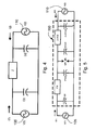
- Figs. 1 and 3 the case of a phase A to ground fault is considered.
- the equations for B to ground faults or C to ground faults (not shown in Fig. 3 ) are similar, except the quantities from the appropriate phase are used.
- phase to phase fault is simpler because zero sequence coupling is not a concern.
- the A phase to B phase ground fault is considered using the circuit model shown in Fig. 3 .
- the single line to ground fault equations are applied to each of phases A and B.
- V A F V A 1 - F ⁇ I A 1 - I ⁇ 0 1 ⁇ Z + I ⁇ 0 1 ⁇ Z ⁇ 0 - F m ⁇ I ⁇ 0 ⁇ M ⁇ Z ⁇ 0 ⁇ M
- V B F V B 1 - F ⁇ I B 1 - I ⁇ 0 1 ⁇ Z + I ⁇ 0 1 ⁇ Z ⁇ 0 - F m ⁇ I ⁇ 0 ⁇ M ⁇ Z ⁇ 0 ⁇ M and calculate the fault current for each of phases and A and B:
- I A F I A 1 + I A 2
- I B F I B 1 + I B 2 and use the results of equations (28) to (31) to determine the phase to phase resistance:
- R ⁇ F 2 ⁇ Real ⁇ V A F - V B F I A F - I B F in order to finally compute the ground resistance of the fault 150:
- R g F 1 2 ⁇ Real
- the resistance of the fault 150 can be computed in different ways as described above to account for fault type and mutual coupling.
- the fault resistance information combined with the fault location enables operators of power transmission lines to more effectively manage their systems.
- the information can be obtained from any terminal connected to the minimum number of other terminals to receive the necessary data for determining the fault location and/or fault resistance.
- the multi-ended fault location system can include charging current compensation in the determination of the fault location to further enhance the accuracy of the fault locating system.
- the model circuit shown in Fig. 4 approximates the network reasonably well.
- the model of Fig. 4 is equivalent to presuming that the total charging current depends on the total line capacitance and the average of the voltages V(1), V(2) at both ends of the lines.
- the implicit assumption in this current compensation model is that the voltage on the line varies linearly along the line from one end to the other. This is true during normal (unfaulted) conditions, but is not true during faulted conditions. Accordingly, the result is that these assumptions are violated by a fault condition. This works well for fault detection, but requires a further investigation of the effect of charging current on fault location.
- the voltage profile on the line is approximately two straight lines from the terminals to the fault, which results in the model shown in Fig. 5 .
- Equations (35) and (36) determine the relationships between voltages and currents that can be used subsequently to determine the accuracy of an estimate of fault location.
- the equations could alternatively be used to determine a least mean square estimate of fault location.
- the process leads to a fourth order polynomial in F, with rather complicated coefficients, so that it is not efficient to implement this algorithm to produce real time or near real time solutions because the numerical solution would have to be used in real-time as the fourth order polynomial cannot be solved priori in a general case. Since an approximation is needed anyway, a more efficient, simpler approach is to use the compensated currents given by equation (34) in the location algorithms and analyze the resulting error in fault location.
- the composite current phasors can be expressed in terms of the voltage at the fault 150 and the terminal 105, 110 voltages by rearranging the equations (35), (36).
- V ⁇ 1 - F ⁇ V 1 + F ⁇ V 2 - V F
- Equation (40) V 1 - V 2 Z + F ⁇ V 1 ⁇ j ⁇ ⁇ C 2 + V ⁇ F ⁇ Z
- I 2 V 2 - V 1 Z + 1 - F ⁇ V 2 ⁇ j ⁇ ⁇ C 2 + V ⁇ 1 - F ⁇ Z
- equation (45) provides excellent accuracy for faults occurring near either end of the line because the error terms go to zero as F goes to 0 or 1.
- equation (45) produces highly accurate results when faults are located in other positions on the line as well. Even for the worst case for a fault near the middle of the line, the error is very small, which will be shown by the following analysis.
- equation (45) produces the following approximation to the actual fault location: Real ⁇ V 1 - V 2 Z + Î 2 Î 1 + Î 2 ⁇ F ⁇ Real ⁇ V ⁇ - Z ⁇ V 2 ⁇ j ⁇ ⁇ C 8 V ⁇ - Z ⁇ V 1 ⁇ j ⁇ ⁇ C 8 - Z ⁇ V 1 - V 2 ⁇ j ⁇ ⁇ C 16 ⁇ F - 1 2 ⁇ Real ⁇ Z ⁇ V 1 - V 2 ⁇ j ⁇ ⁇ C 16 V ⁇ - Z ⁇ V 1 ⁇ j ⁇ ⁇ C 8 - Z ⁇ V 1 - V 2 ⁇ j ⁇ ⁇ C 16 - Z ⁇ V 1 - V 2 ⁇ j ⁇ ⁇ C 16 - Z ⁇ V 1 - V 2 ⁇ j ⁇ ⁇ C 16
- equations (45) and (46) have small error even when the fault 150 is located near the midpoint of the transmission line.
- the following term in equation (46) represents a residual error: error ⁇ - 1 2 ⁇ Real ⁇ Z ⁇ V 1 - V 2 ⁇ j ⁇ ⁇ C 16 V ⁇ - Z ⁇ V 1 ⁇ j ⁇ ⁇ C 8 - Z ⁇ V 1 - V 2 ⁇ j ⁇ ⁇ C 16
- the factor is approximately related to the inductance and capacitance of the line by: j ⁇ Z ⁇ ⁇ ⁇ C ⁇ - ⁇ 2 ⁇ L ⁇ C
- the factor given by equation (49) is the square of the ratio of the power system frequency divided by the resonant frequency of the line, which is also the square of the ratio of the length of the line divided by one wavelength at power system frequency: Z ⁇ ⁇ ⁇ C ⁇ - ⁇ 2 ⁇ L ⁇ C ⁇ - ⁇ 2 ⁇ resonant 2 ⁇ D 2 D ⁇ 2
- equation (47) can be approximated by: error ⁇ 1 32 ⁇ D 2 D resonant 2 ⁇ Real ⁇ V 1 - V 2 V ⁇
- equation (37) with charging-current compensated currents for a 160 km long line is negligible.
- equation (51) it can also be seen that the residual error will grow as the square of the length of the line. For example, increasing the length of the line in the previous example from 160 km to 800 km will increase the error from 0.2% to 5%, establishing a practical upper limit on the applicability of simple charge compensation.
- charging current must be modeled by the differential equations that describe long transmission lines.
- any means-plus-function clause is intended to cover the structures described herein as performing the recited function and not only structural equivalents but also equivalent structures.
- Other substitutions, modifications, changes and omissions may be made in the design, operating conditions and arrangement of the preferred and other exemplary embodiments without departing from the spirit of the embodiments of the invention as expressed in the appended claims. Therefore, the technical scope of the present invention encompasses not only those embodiments described above, but all that fall within the scope of the appended claims.
Landscapes
- Physics & Mathematics (AREA)
- General Physics & Mathematics (AREA)
- Locating Faults (AREA)
- Emergency Protection Circuit Devices (AREA)
- Maintenance And Management Of Digital Transmission (AREA)
- Remote Monitoring And Control Of Power-Distribution Networks (AREA)
- Monitoring And Testing Of Transmission In General (AREA)
Applications Claiming Priority (1)
| Application Number | Priority Date | Filing Date | Title |
|---|---|---|---|
| US11/615,103 US7472026B2 (en) | 2006-12-22 | 2006-12-22 | Multi-ended fault location system |
Publications (3)
| Publication Number | Publication Date |
|---|---|
| EP1939639A2 EP1939639A2 (en) | 2008-07-02 |
| EP1939639A3 EP1939639A3 (en) | 2012-01-18 |
| EP1939639B1 true EP1939639B1 (en) | 2013-06-19 |
Family
ID=39253881
Family Applications (1)
| Application Number | Title | Priority Date | Filing Date |
|---|---|---|---|
| EP07123293.8A Active EP1939639B1 (en) | 2006-12-22 | 2007-12-14 | System and method for locating faults in a multi-ended power transmission line |
Country Status (13)
| Country | Link |
|---|---|
| US (1) | US7472026B2 (enExample) |
| EP (1) | EP1939639B1 (enExample) |
| JP (1) | JP5490989B2 (enExample) |
| KR (1) | KR101357952B1 (enExample) |
| CN (1) | CN101207281B (enExample) |
| AU (1) | AU2007240222B2 (enExample) |
| BR (1) | BRPI0705537A (enExample) |
| CA (1) | CA2613764C (enExample) |
| ES (1) | ES2425175T3 (enExample) |
| MX (1) | MX2007015435A (enExample) |
| NO (1) | NO338774B1 (enExample) |
| SG (1) | SG144050A1 (enExample) |
| TW (1) | TWI425225B (enExample) |
Families Citing this family (63)
| Publication number | Priority date | Publication date | Assignee | Title |
|---|---|---|---|---|
| US7725295B2 (en) * | 2006-11-01 | 2010-05-25 | Abb Research Ltd. | Cable fault detection |
| US8248082B2 (en) | 2007-01-17 | 2012-08-21 | International Business Machines Corporation | Method for determining the current return path integrity in an electric device connected or connectable to a further device |
| CA2585820A1 (fr) * | 2007-04-18 | 2008-10-18 | Hydro-Quebec | Localisation de defaut sur un reseau electrique par mesures de tension distribuees |
| WO2009136975A2 (en) * | 2008-05-09 | 2009-11-12 | Accenture Global Services Gmbh | Method and system for managing a power grid |
| US8892375B2 (en) | 2008-05-09 | 2014-11-18 | Accenture Global Services Limited | Power grid outage and fault condition management |
| US20110004446A1 (en) * | 2008-12-15 | 2011-01-06 | Accenture Global Services Gmbh | Intelligent network |
| NZ593113A (en) * | 2008-12-15 | 2013-10-25 | Accenture Global Services Ltd | Power grid outage and fault condition management |
| US8103467B2 (en) * | 2009-01-14 | 2012-01-24 | Accenture Global Services Limited | Determination of distribution transformer voltages based on metered loads |
| US8103466B2 (en) * | 2009-01-14 | 2012-01-24 | Accenture Global Services Limited | Distribution system analysis using meter data |
| US8315827B2 (en) * | 2009-02-26 | 2012-11-20 | Southern California Edison | Fault region location system |
| US8089293B2 (en) * | 2009-04-20 | 2012-01-03 | Tektronix, Inc. | Test and measurement instrument and method of configuring using a sensed impedance |
| US8649142B2 (en) * | 2009-09-17 | 2014-02-11 | Schweitzer Engineering Laboratories Inc | Equivalent alpha plane fault determination for a multi-terminal power apparatus |
| US8553379B2 (en) * | 2009-09-17 | 2013-10-08 | Schweitzer Engineering Laboratories Inc | Transformer differential protection |
| US8154836B2 (en) * | 2009-09-17 | 2012-04-10 | Schweitzer Engineering Laboratories, Inc. | Line current differential protection upon loss of an external time reference |
| US8289668B2 (en) * | 2009-09-17 | 2012-10-16 | Schweitzer Engineering Laboratories, Inc. | Charging current compensation for line current differential protection |
| JP2011100347A (ja) * | 2009-11-06 | 2011-05-19 | Sony Corp | 電力供給装置、電力受電装置、電力供給システム及び障害復帰方法 |
| TWI383162B (zh) * | 2009-12-22 | 2013-01-21 | Univ Nat Taipei Technology | Fault location method |
| NZ607733A (en) | 2010-07-30 | 2014-09-26 | Accenture Global Services Ltd | Intelligent core engine |
| US8942954B2 (en) * | 2010-09-16 | 2015-01-27 | Schweitzer Engineering Laboratories, Inc. | Fault location in a non-homogeneous electric power line |
| US8717725B2 (en) | 2010-12-02 | 2014-05-06 | Schweitzer Engineering Laboratories Inc | Dual-comparator restricted earth fault protection |
| RU2464582C2 (ru) * | 2010-12-27 | 2012-10-20 | Общество с ограниченной ответственностью "НПП Бреслер" (ООО "НПП Бреслер") | Способ определения места повреждения разветвленной линии электропередачи с несколькими источниками питания |
| US8461797B2 (en) | 2011-01-28 | 2013-06-11 | I-Shou University | Current direction detection module |
| CN102565597B (zh) * | 2012-02-14 | 2015-01-07 | 广东易事特电源股份有限公司 | 一种应用同步相量技术的动态输电线容量估计方法 |
| US9008982B2 (en) | 2012-03-09 | 2015-04-14 | Schweitzer Engineering Laboratories, Inc. | Systems and methods for determining residual flux in a power transformer |
| US8963558B2 (en) | 2012-10-31 | 2015-02-24 | General Electric Company | Current differential protection |
| CN103032626B (zh) * | 2012-12-12 | 2015-03-18 | 济南大学 | 调节阀故障诊断系统及方法 |
| CN103197204B (zh) * | 2013-04-07 | 2015-04-29 | 山东电力集团公司德州供电公司 | 多端线路故障定位的混合型方法 |
| CN103245893B (zh) * | 2013-04-10 | 2015-12-23 | 昆明理工大学 | 一种基于自然频率的辐射状配网分层分布式ann故障定位方法 |
| CN103296644B (zh) * | 2013-05-19 | 2016-02-17 | 国家电网公司 | 输电线路复合序分量电压保护方法 |
| CN104133155B (zh) * | 2014-07-09 | 2016-10-05 | 华中科技大学 | 一种电缆局部缺陷诊断方法 |
| CN104316842B (zh) * | 2014-11-14 | 2017-04-26 | 国家电网公司 | 利用相间故障位置因子相位特性实现线路相间故障单端测距方法 |
| RU2586453C1 (ru) * | 2015-04-22 | 2016-06-10 | федеральное государственное бюджетное образовательное учреждение высшего образования "Иркутский национальный исследовательский технический университет" (ФГБОУ ВО "ИРНИТУ") | Способ определения места короткого замыкания на воздушной линии электропередачи при несинхронизированных замерах с двух её концов |
| CN105158640B (zh) * | 2015-09-15 | 2018-07-20 | 江苏金智科技股份有限公司 | 多电源供电系统及基于gps与电流波形的故障定位方法 |
| CN109275337A (zh) * | 2016-06-14 | 2019-01-25 | 施瓦哲工程实验有限公司 | 行波故障检测系统的相选择 |
| US10802054B2 (en) | 2017-09-22 | 2020-10-13 | Schweitzer Engineering Laboratories, Inc. | High-fidelity voltage measurement using a capacitance-coupled voltage transformer |
| US11038342B2 (en) | 2017-09-22 | 2021-06-15 | Schweitzer Engineering Laboratories, Inc. | Traveling wave identification using distortions for electric power system protection |
| WO2019060841A1 (en) | 2017-09-22 | 2019-03-28 | Schweitzer Engineering Laboratories, Inc. | HIGH RELIABILITY VOLTAGE MEASUREMENT USING A RESISTIVE DIVIDER IN A CAPACITIVE COUPLING VOLTAGE TRANSFORMER |
| JP7005301B2 (ja) * | 2017-11-13 | 2022-01-21 | 株式会社東芝 | 故障点標定システム |
| CN108054737B (zh) * | 2017-12-08 | 2019-06-21 | 国网青海省电力公司 | 一种串补不对称运行线路后备零序保护定值自动调整方法 |
| US11327105B2 (en) | 2017-12-29 | 2022-05-10 | Hitachi Energy Switzerland Ag | Fault location in multi-terminal tapped lines |
| WO2019186490A1 (en) | 2018-03-31 | 2019-10-03 | Abb Schweiz Ag | Method and device for protection in a multi-terminal power transmission system |
| CN108845183B (zh) * | 2018-07-03 | 2020-07-14 | 西北工业大学 | 一种多电飞机电缆阻抗测量方法 |
| CN109470994A (zh) * | 2018-11-09 | 2019-03-15 | 南京大贺电力科技有限公司 | 用于配电网的故障线路判别系统及方法 |
| US11099238B2 (en) | 2019-03-27 | 2021-08-24 | General Electric Company | Distributed control modules with built-in tests and control-preserving fault responses |
| US11187727B2 (en) | 2019-04-29 | 2021-11-30 | Schweitzer Engineering Laboratories, Inc. | Capacitance-coupled voltage transformer monitoring |
| CN110346688B (zh) * | 2019-07-31 | 2021-03-02 | 广东电网有限责任公司 | 一种110kV及以上高压复杂电缆故障快速分段判别及定位方法 |
| US11177645B2 (en) | 2019-11-22 | 2021-11-16 | Schweitzer Engineering Laboratories, Inc. | Systems and methods for improving restricted earth fault protection |
| US11476655B2 (en) | 2020-01-14 | 2022-10-18 | Schweitzer Engineering Laboratories, Inc. | Trapped charge estimation |
| CN111413583B (zh) * | 2020-03-19 | 2023-08-25 | 国网湖北省电力有限公司荆门供电公司 | 一种配电网区段定位的实时线性整数规划方法 |
| US11575253B2 (en) | 2020-05-12 | 2023-02-07 | Schweitzer Engineering Laboratories, Inc. | Controlled three-pole close for transmission lines |
| CN113933744B (zh) * | 2020-07-13 | 2023-11-03 | 福建先德能源科技有限公司 | 一种单相接地故障的判别方法及装置 |
| US11233389B1 (en) | 2020-10-30 | 2022-01-25 | Schweitzer Engineering Laboratories, Inc. | Controlled three-pole close for transformers |
| US11411390B2 (en) | 2020-12-31 | 2022-08-09 | Schweitzer Engineering Laboratories, Inc. | Secure and dependable restricted earth fault protection for electric power generators and transformers |
| CN113364910B (zh) * | 2021-06-08 | 2022-09-02 | Tcl通讯(宁波)有限公司 | 一种信号处理方法、装置、设备及存储介质 |
| US20230069041A1 (en) * | 2021-08-26 | 2023-03-02 | Schweitzer Engineering Laboratories, Inc. | Detection of incipient failures in instrument transformers |
| CN113848389B (zh) * | 2021-09-23 | 2023-06-13 | 中国南方电网有限责任公司超高压输电公司广州局 | 互耦输电线路的零序阻抗估计方法和装置 |
| CN114002544B (zh) * | 2021-10-11 | 2024-03-08 | 北京四方继保工程技术有限公司 | 一种多端线路保护故障定位及测距的方法 |
| CN114325211B (zh) * | 2021-11-05 | 2024-12-27 | 青岛科技大学 | 一种混合多端直流输电线路的故障定位方法 |
| CN114578184B (zh) * | 2021-11-29 | 2022-11-25 | 昆明理工大学 | 一种直流输电线路双端行波频差比值故障测距方法及系统 |
| US12316112B2 (en) | 2022-07-12 | 2025-05-27 | Schweitzer Engineering Laboratories, Inc. | Breaker control units and related systems and methods |
| CN115542077A (zh) * | 2022-09-09 | 2022-12-30 | 华电电力科学研究院有限公司 | 基于风电场集电线路和箱变参数的相间故障多端测距方法 |
| US20250012839A1 (en) * | 2023-07-06 | 2025-01-09 | Abb Schweiz Ag | Fault location detection in tapped power distribution lines |
| CN118094133B (zh) * | 2023-12-13 | 2024-10-01 | 国网上海市电力公司 | 针对安装在sg端的同步相量测量单元的故障检测方法 |
Family Cites Families (17)
| Publication number | Priority date | Publication date | Assignee | Title |
|---|---|---|---|---|
| US4275429A (en) * | 1979-10-12 | 1981-06-23 | Westinghouse Electric Corp. | Protective relay apparatus |
| AU582039B2 (en) * | 1986-03-07 | 1989-03-09 | Mitsubishi Denki Kabushiki Kaisha | Fault point locating method, fault point resistance measuring method, and impendance to fault point measuring method and apparatuses therefor |
| US4725914A (en) * | 1986-12-16 | 1988-02-16 | Westinghouse Electric Corp. | Protective relay system for performing selective-pole trip determination |
| US4871971A (en) * | 1987-01-15 | 1989-10-03 | Jeerings Donald I | High impedance fault analyzer in electric power distribution networks |
| US5809045A (en) * | 1996-09-13 | 1998-09-15 | General Electric Company | Digital current differential system |
| IES80796B2 (en) * | 1997-08-28 | 1999-02-24 | Electricity Supply Board | Fault detection apparatus and method of detecting faults in an electrical distribution network |
| CN1103451C (zh) * | 1997-12-04 | 2003-03-19 | 中国人民解放军第二炮兵工程学院技术开发中心 | 高压架空线路在线故障测距方法及仪器装置 |
| US6256592B1 (en) | 1999-02-24 | 2001-07-03 | Schweitzer Engineering Laboratories, Inc. | Multi-ended fault location system |
| JP2000329813A (ja) * | 1999-05-18 | 2000-11-30 | Mitsubishi Electric Corp | 部分放電検出装置 |
| KR100394134B1 (ko) * | 2001-02-20 | 2003-08-09 | 학교법인 성균관대학 | 웨이브렛변환을 이용한 고저항 지락사고의 검출방법 및이에 의한 고장거리 측정방법 |
| TW548886B (en) * | 2001-10-16 | 2003-08-21 | Know Entpr Co Ltd U | Three-phase shunt type active power filter capable of operating in parallel |
| US6879917B2 (en) | 2002-06-14 | 2005-04-12 | Progress Energy Carolinas Inc. | Double-ended distance-to-fault location system using time-synchronized positive-or negative-sequence quantities |
| CN1228642C (zh) * | 2003-08-12 | 2005-11-23 | 武汉大学 | 一种采用多端信号的输电线路精确故障定位方法 |
| CN1289913C (zh) * | 2003-09-03 | 2006-12-13 | 武汉大学 | 一种带串补的输电线路的精确故障定位方法 |
| CN1529179A (zh) * | 2003-10-09 | 2004-09-15 | 武汉大学 | 一种t型接线输电线路故障的精确定位方法 |
| TWI239133B (en) * | 2003-11-12 | 2005-09-01 | Ind Tech Res Inst | A method and a device for rapidly detecting abnormal voltage on a static transfer switch |
| KR200436076Y1 (ko) | 2006-11-04 | 2007-05-08 | 김보경 | 절연감시시스템 |
-
2006
- 2006-12-22 US US11/615,103 patent/US7472026B2/en active Active
-
2007
- 2007-12-06 CA CA2613764A patent/CA2613764C/en active Active
- 2007-12-06 MX MX2007015435A patent/MX2007015435A/es active IP Right Grant
- 2007-12-07 SG SG200718423-7A patent/SG144050A1/en unknown
- 2007-12-10 AU AU2007240222A patent/AU2007240222B2/en not_active Ceased
- 2007-12-10 TW TW096147051A patent/TWI425225B/zh not_active IP Right Cessation
- 2007-12-11 BR BRPI0705537-4A patent/BRPI0705537A/pt not_active Application Discontinuation
- 2007-12-14 ES ES07123293T patent/ES2425175T3/es active Active
- 2007-12-14 EP EP07123293.8A patent/EP1939639B1/en active Active
- 2007-12-19 JP JP2007326683A patent/JP5490989B2/ja not_active Expired - Fee Related
- 2007-12-20 NO NO20076599A patent/NO338774B1/no unknown
- 2007-12-20 KR KR1020070134329A patent/KR101357952B1/ko not_active Expired - Fee Related
- 2007-12-21 CN CN200710160061.4A patent/CN101207281B/zh not_active Expired - Fee Related
Also Published As
| Publication number | Publication date |
|---|---|
| JP2008157940A (ja) | 2008-07-10 |
| EP1939639A3 (en) | 2012-01-18 |
| CA2613764A1 (en) | 2008-06-22 |
| CN101207281B (zh) | 2015-08-19 |
| NO338774B1 (no) | 2016-10-17 |
| US7472026B2 (en) | 2008-12-30 |
| AU2007240222B2 (en) | 2012-02-09 |
| EP1939639A2 (en) | 2008-07-02 |
| JP5490989B2 (ja) | 2014-05-14 |
| SG144050A1 (en) | 2008-07-29 |
| TW200837368A (en) | 2008-09-16 |
| KR20080059062A (ko) | 2008-06-26 |
| US20080150544A1 (en) | 2008-06-26 |
| MX2007015435A (es) | 2009-02-20 |
| CA2613764C (en) | 2016-05-03 |
| CN101207281A (zh) | 2008-06-25 |
| AU2007240222A1 (en) | 2008-07-10 |
| TWI425225B (zh) | 2014-02-01 |
| NO20076599L (no) | 2008-06-23 |
| BRPI0705537A (pt) | 2008-08-12 |
| ES2425175T3 (es) | 2013-10-11 |
| KR101357952B1 (ko) | 2014-02-03 |
Similar Documents
| Publication | Publication Date | Title |
|---|---|---|
| EP1939639B1 (en) | System and method for locating faults in a multi-ended power transmission line | |
| CN106199328B (zh) | 故障位置检测以及距离保护设备及相关方法 | |
| RU2419802C2 (ru) | Способ и устройство для определения места короткого замыкания в силовой линии электропередачи или распределительной линии с двумя терминалами | |
| US9476931B2 (en) | Method for fault location analysis of ungrounded distribution systems | |
| KR100350722B1 (ko) | 병행 2회선 송전선로상에서의 고장점 표정방법 및 장치 | |
| EP3564687B1 (en) | Determination of power transmission line parameters using asynchronous measurements | |
| CN103869221B (zh) | 基于sv网络采样的双回线路单相接地故障距离测量方法 | |
| EP1342095B1 (en) | Fault location method and device | |
| CN104090210B (zh) | 双回线路非同名相跨线接地故障单端测距方法 | |
| WO2019166903A1 (en) | Method and device for fault location in a two-terminal transmission system | |
| De Andrade et al. | Impedance-based fault location analysis for transmission lines | |
| CN104764969A (zh) | 基于接地电阻实测的双回线路非同名相跨线高阻接地故障定位方法 | |
| CN104090213A (zh) | 双回线路非同名相跨线接地故障的定位方法 | |
| CN104062551B (zh) | 一种双回线路非同名相跨线接地故障快速定位方法 | |
| Voloh et al. | Fault locator based on line current differential relays synchronized measurements | |
| US20240118330A1 (en) | Fault location estimation using incremental quantities | |
| Eng et al. | Single-ended traveling wave based fault location on two terminal transmission lines | |
| JP7134846B2 (ja) | 送電線保護リレー装置 | |
| Courtney et al. | Fault location on a distribution network using a decentralised analysis process | |
| Izykowski et al. | Location of faults in partially parallel transmission networks | |
| Rosolowski et al. | Fault location algorithm for use with current differential protective relays of double-circuit line | |
| Sharma et al. | Remote fault estimation and thevenin impedance calculation from relays event reports | |
| Kim | Fault Location Overview |
Legal Events
| Date | Code | Title | Description |
|---|---|---|---|
| PUAI | Public reference made under article 153(3) epc to a published international application that has entered the european phase |
Free format text: ORIGINAL CODE: 0009012 |
|
| AK | Designated contracting states |
Kind code of ref document: A2 Designated state(s): AT BE BG CH CY CZ DE DK EE ES FI FR GB GR HU IE IS IT LI LT LU LV MC MT NL PL PT RO SE SI SK TR |
|
| AX | Request for extension of the european patent |
Extension state: AL BA HR MK RS |
|
| PUAL | Search report despatched |
Free format text: ORIGINAL CODE: 0009013 |
|
| AK | Designated contracting states |
Kind code of ref document: A3 Designated state(s): AT BE BG CH CY CZ DE DK EE ES FI FR GB GR HU IE IS IT LI LT LU LV MC MT NL PL PT RO SE SI SK TR |
|
| AX | Request for extension of the european patent |
Extension state: AL BA HR MK RS |
|
| RIC1 | Information provided on ipc code assigned before grant |
Ipc: G01R 27/18 20060101ALI20111209BHEP Ipc: G01R 31/08 20060101AFI20111209BHEP |
|
| 17P | Request for examination filed |
Effective date: 20120718 |
|
| AKX | Designation fees paid |
Designated state(s): AT BE BG CH CY CZ DE DK EE ES FI FR GB GR HU IE IS IT LI LT LU LV MC MT NL PL PT RO SE SI SK TR |
|
| GRAP | Despatch of communication of intention to grant a patent |
Free format text: ORIGINAL CODE: EPIDOSNIGR1 |
|
| GRAS | Grant fee paid |
Free format text: ORIGINAL CODE: EPIDOSNIGR3 |
|
| GRAA | (expected) grant |
Free format text: ORIGINAL CODE: 0009210 |
|
| AK | Designated contracting states |
Kind code of ref document: B1 Designated state(s): AT BE BG CH CY CZ DE DK EE ES FI FR GB GR HU IE IS IT LI LT LU LV MC MT NL PL PT RO SE SI SK TR |
|
| REG | Reference to a national code |
Ref country code: GB Ref legal event code: FG4D |
|
| REG | Reference to a national code |
Ref country code: CH Ref legal event code: EP |
|
| REG | Reference to a national code |
Ref country code: AT Ref legal event code: REF Ref document number: 617935 Country of ref document: AT Kind code of ref document: T Effective date: 20130715 |
|
| REG | Reference to a national code |
Ref country code: IE Ref legal event code: FG4D |
|
| REG | Reference to a national code |
Ref country code: DE Ref legal event code: R096 Ref document number: 602007031099 Country of ref document: DE Effective date: 20130814 |
|
| REG | Reference to a national code |
Ref country code: ES Ref legal event code: FG2A Ref document number: 2425175 Country of ref document: ES Kind code of ref document: T3 Effective date: 20131011 |
|
| PG25 | Lapsed in a contracting state [announced via postgrant information from national office to epo] |
Ref country code: SI Free format text: LAPSE BECAUSE OF FAILURE TO SUBMIT A TRANSLATION OF THE DESCRIPTION OR TO PAY THE FEE WITHIN THE PRESCRIBED TIME-LIMIT Effective date: 20130619 Ref country code: SE Free format text: LAPSE BECAUSE OF FAILURE TO SUBMIT A TRANSLATION OF THE DESCRIPTION OR TO PAY THE FEE WITHIN THE PRESCRIBED TIME-LIMIT Effective date: 20130619 Ref country code: LT Free format text: LAPSE BECAUSE OF FAILURE TO SUBMIT A TRANSLATION OF THE DESCRIPTION OR TO PAY THE FEE WITHIN THE PRESCRIBED TIME-LIMIT Effective date: 20130619 Ref country code: GR Free format text: LAPSE BECAUSE OF FAILURE TO SUBMIT A TRANSLATION OF THE DESCRIPTION OR TO PAY THE FEE WITHIN THE PRESCRIBED TIME-LIMIT Effective date: 20130920 Ref country code: FI Free format text: LAPSE BECAUSE OF FAILURE TO SUBMIT A TRANSLATION OF THE DESCRIPTION OR TO PAY THE FEE WITHIN THE PRESCRIBED TIME-LIMIT Effective date: 20130619 |
|
| REG | Reference to a national code |
Ref country code: AT Ref legal event code: MK05 Ref document number: 617935 Country of ref document: AT Kind code of ref document: T Effective date: 20130619 |
|
| REG | Reference to a national code |
Ref country code: LT Ref legal event code: MG4D |
|
| PG25 | Lapsed in a contracting state [announced via postgrant information from national office to epo] |
Ref country code: BG Free format text: LAPSE BECAUSE OF FAILURE TO SUBMIT A TRANSLATION OF THE DESCRIPTION OR TO PAY THE FEE WITHIN THE PRESCRIBED TIME-LIMIT Effective date: 20130919 |
|
| REG | Reference to a national code |
Ref country code: NL Ref legal event code: VDEP Effective date: 20130619 |
|
| PG25 | Lapsed in a contracting state [announced via postgrant information from national office to epo] |
Ref country code: LV Free format text: LAPSE BECAUSE OF FAILURE TO SUBMIT A TRANSLATION OF THE DESCRIPTION OR TO PAY THE FEE WITHIN THE PRESCRIBED TIME-LIMIT Effective date: 20130619 |
|
| PG25 | Lapsed in a contracting state [announced via postgrant information from national office to epo] |
Ref country code: EE Free format text: LAPSE BECAUSE OF FAILURE TO SUBMIT A TRANSLATION OF THE DESCRIPTION OR TO PAY THE FEE WITHIN THE PRESCRIBED TIME-LIMIT Effective date: 20130619 Ref country code: CY Free format text: LAPSE BECAUSE OF FAILURE TO SUBMIT A TRANSLATION OF THE DESCRIPTION OR TO PAY THE FEE WITHIN THE PRESCRIBED TIME-LIMIT Effective date: 20130626 Ref country code: BE Free format text: LAPSE BECAUSE OF FAILURE TO SUBMIT A TRANSLATION OF THE DESCRIPTION OR TO PAY THE FEE WITHIN THE PRESCRIBED TIME-LIMIT Effective date: 20130619 Ref country code: PT Free format text: LAPSE BECAUSE OF FAILURE TO SUBMIT A TRANSLATION OF THE DESCRIPTION OR TO PAY THE FEE WITHIN THE PRESCRIBED TIME-LIMIT Effective date: 20131021 Ref country code: IS Free format text: LAPSE BECAUSE OF FAILURE TO SUBMIT A TRANSLATION OF THE DESCRIPTION OR TO PAY THE FEE WITHIN THE PRESCRIBED TIME-LIMIT Effective date: 20131019 Ref country code: SK Free format text: LAPSE BECAUSE OF FAILURE TO SUBMIT A TRANSLATION OF THE DESCRIPTION OR TO PAY THE FEE WITHIN THE PRESCRIBED TIME-LIMIT Effective date: 20130619 Ref country code: CZ Free format text: LAPSE BECAUSE OF FAILURE TO SUBMIT A TRANSLATION OF THE DESCRIPTION OR TO PAY THE FEE WITHIN THE PRESCRIBED TIME-LIMIT Effective date: 20130619 Ref country code: AT Free format text: LAPSE BECAUSE OF FAILURE TO SUBMIT A TRANSLATION OF THE DESCRIPTION OR TO PAY THE FEE WITHIN THE PRESCRIBED TIME-LIMIT Effective date: 20130619 |
|
| PG25 | Lapsed in a contracting state [announced via postgrant information from national office to epo] |
Ref country code: PL Free format text: LAPSE BECAUSE OF FAILURE TO SUBMIT A TRANSLATION OF THE DESCRIPTION OR TO PAY THE FEE WITHIN THE PRESCRIBED TIME-LIMIT Effective date: 20130619 Ref country code: NL Free format text: LAPSE BECAUSE OF FAILURE TO SUBMIT A TRANSLATION OF THE DESCRIPTION OR TO PAY THE FEE WITHIN THE PRESCRIBED TIME-LIMIT Effective date: 20130619 Ref country code: RO Free format text: LAPSE BECAUSE OF FAILURE TO SUBMIT A TRANSLATION OF THE DESCRIPTION OR TO PAY THE FEE WITHIN THE PRESCRIBED TIME-LIMIT Effective date: 20130619 |
|
| PG25 | Lapsed in a contracting state [announced via postgrant information from national office to epo] |
Ref country code: CY Free format text: LAPSE BECAUSE OF FAILURE TO SUBMIT A TRANSLATION OF THE DESCRIPTION OR TO PAY THE FEE WITHIN THE PRESCRIBED TIME-LIMIT Effective date: 20130619 |
|
| PLBE | No opposition filed within time limit |
Free format text: ORIGINAL CODE: 0009261 |
|
| STAA | Information on the status of an ep patent application or granted ep patent |
Free format text: STATUS: NO OPPOSITION FILED WITHIN TIME LIMIT |
|
| PG25 | Lapsed in a contracting state [announced via postgrant information from national office to epo] |
Ref country code: DK Free format text: LAPSE BECAUSE OF FAILURE TO SUBMIT A TRANSLATION OF THE DESCRIPTION OR TO PAY THE FEE WITHIN THE PRESCRIBED TIME-LIMIT Effective date: 20130619 |
|
| 26N | No opposition filed |
Effective date: 20140320 |
|
| PG25 | Lapsed in a contracting state [announced via postgrant information from national office to epo] |
Ref country code: IT Free format text: LAPSE BECAUSE OF FAILURE TO SUBMIT A TRANSLATION OF THE DESCRIPTION OR TO PAY THE FEE WITHIN THE PRESCRIBED TIME-LIMIT Effective date: 20130619 |
|
| REG | Reference to a national code |
Ref country code: DE Ref legal event code: R097 Ref document number: 602007031099 Country of ref document: DE Effective date: 20140320 |
|
| REG | Reference to a national code |
Ref country code: CH Ref legal event code: PL |
|
| PG25 | Lapsed in a contracting state [announced via postgrant information from national office to epo] |
Ref country code: MC Free format text: LAPSE BECAUSE OF FAILURE TO SUBMIT A TRANSLATION OF THE DESCRIPTION OR TO PAY THE FEE WITHIN THE PRESCRIBED TIME-LIMIT Effective date: 20130619 Ref country code: LU Free format text: LAPSE BECAUSE OF FAILURE TO SUBMIT A TRANSLATION OF THE DESCRIPTION OR TO PAY THE FEE WITHIN THE PRESCRIBED TIME-LIMIT Effective date: 20131214 |
|
| REG | Reference to a national code |
Ref country code: IE Ref legal event code: MM4A |
|
| PG25 | Lapsed in a contracting state [announced via postgrant information from national office to epo] |
Ref country code: CH Free format text: LAPSE BECAUSE OF NON-PAYMENT OF DUE FEES Effective date: 20131231 Ref country code: IE Free format text: LAPSE BECAUSE OF NON-PAYMENT OF DUE FEES Effective date: 20131214 Ref country code: LI Free format text: LAPSE BECAUSE OF NON-PAYMENT OF DUE FEES Effective date: 20131231 |
|
| PG25 | Lapsed in a contracting state [announced via postgrant information from national office to epo] |
Ref country code: TR Free format text: LAPSE BECAUSE OF FAILURE TO SUBMIT A TRANSLATION OF THE DESCRIPTION OR TO PAY THE FEE WITHIN THE PRESCRIBED TIME-LIMIT Effective date: 20130619 |
|
| PG25 | Lapsed in a contracting state [announced via postgrant information from national office to epo] |
Ref country code: HU Free format text: LAPSE BECAUSE OF FAILURE TO SUBMIT A TRANSLATION OF THE DESCRIPTION OR TO PAY THE FEE WITHIN THE PRESCRIBED TIME-LIMIT; INVALID AB INITIO Effective date: 20071214 |
|
| PG25 | Lapsed in a contracting state [announced via postgrant information from national office to epo] |
Ref country code: MT Free format text: LAPSE BECAUSE OF FAILURE TO SUBMIT A TRANSLATION OF THE DESCRIPTION OR TO PAY THE FEE WITHIN THE PRESCRIBED TIME-LIMIT Effective date: 20130619 |
|
| REG | Reference to a national code |
Ref country code: FR Ref legal event code: PLFP Year of fee payment: 9 |
|
| REG | Reference to a national code |
Ref country code: FR Ref legal event code: PLFP Year of fee payment: 10 |
|
| REG | Reference to a national code |
Ref country code: FR Ref legal event code: PLFP Year of fee payment: 11 |
|
| P01 | Opt-out of the competence of the unified patent court (upc) registered |
Effective date: 20230522 |
|
| REG | Reference to a national code |
Ref country code: DE Ref legal event code: R081 Ref document number: 602007031099 Country of ref document: DE Owner name: GENERAL ELECTRIC TECHNOLOGY GMBH, CH Free format text: FORMER OWNER: GENERAL ELECTRIC COMPANY, SCHENECTADY, N.Y., US |
|
| REG | Reference to a national code |
Ref country code: GB Ref legal event code: 732E Free format text: REGISTERED BETWEEN 20240222 AND 20240228 |
|
| PGFP | Annual fee paid to national office [announced via postgrant information from national office to epo] |
Ref country code: ES Payment date: 20240102 Year of fee payment: 17 |
|
| REG | Reference to a national code |
Ref country code: ES Ref legal event code: PC2A Owner name: GENERAL ELECTRIC TECHNOLOGY GMBH Effective date: 20240624 |
|
| PGFP | Annual fee paid to national office [announced via postgrant information from national office to epo] |
Ref country code: DE Payment date: 20241121 Year of fee payment: 18 |
|
| PGFP | Annual fee paid to national office [announced via postgrant information from national office to epo] |
Ref country code: GB Payment date: 20241122 Year of fee payment: 18 |
|
| PGFP | Annual fee paid to national office [announced via postgrant information from national office to epo] |
Ref country code: FR Payment date: 20241121 Year of fee payment: 18 |