EP1936730B1 - Bipolarer Batteriestapel mit übereinander liegenden Separatoren und zugehöriges Herstellungsverfahren - Google Patents
Bipolarer Batteriestapel mit übereinander liegenden Separatoren und zugehöriges Herstellungsverfahren Download PDFInfo
- Publication number
- EP1936730B1 EP1936730B1 EP07121749A EP07121749A EP1936730B1 EP 1936730 B1 EP1936730 B1 EP 1936730B1 EP 07121749 A EP07121749 A EP 07121749A EP 07121749 A EP07121749 A EP 07121749A EP 1936730 B1 EP1936730 B1 EP 1936730B1
- Authority
- EP
- European Patent Office
- Prior art keywords
- bipolar electrode
- sealing
- separator
- collector
- cathode
- Prior art date
- Legal status (The legal status is an assumption and is not a legal conclusion. Google has not performed a legal analysis and makes no representation as to the accuracy of the status listed.)
- Ceased
Links
Images


Classifications
-
- H—ELECTRICITY
- H01—ELECTRIC ELEMENTS
- H01M—PROCESSES OR MEANS, e.g. BATTERIES, FOR THE DIRECT CONVERSION OF CHEMICAL ENERGY INTO ELECTRICAL ENERGY
- H01M10/00—Secondary cells; Manufacture thereof
- H01M10/04—Construction or manufacture in general
- H01M10/0413—Large-sized flat cells or batteries for motive or stationary systems with plate-like electrodes
- H01M10/0418—Large-sized flat cells or batteries for motive or stationary systems with plate-like electrodes with bipolar electrodes
-
- H—ELECTRICITY
- H01—ELECTRIC ELEMENTS
- H01M—PROCESSES OR MEANS, e.g. BATTERIES, FOR THE DIRECT CONVERSION OF CHEMICAL ENERGY INTO ELECTRICAL ENERGY
- H01M10/00—Secondary cells; Manufacture thereof
- H01M10/05—Accumulators with non-aqueous electrolyte
- H01M10/052—Li-accumulators
-
- H—ELECTRICITY
- H01—ELECTRIC ELEMENTS
- H01M—PROCESSES OR MEANS, e.g. BATTERIES, FOR THE DIRECT CONVERSION OF CHEMICAL ENERGY INTO ELECTRICAL ENERGY
- H01M10/00—Secondary cells; Manufacture thereof
- H01M10/05—Accumulators with non-aqueous electrolyte
- H01M10/058—Construction or manufacture
- H01M10/0585—Construction or manufacture of accumulators having only flat construction elements, i.e. flat positive electrodes, flat negative electrodes and flat separators
-
- H—ELECTRICITY
- H01—ELECTRIC ELEMENTS
- H01M—PROCESSES OR MEANS, e.g. BATTERIES, FOR THE DIRECT CONVERSION OF CHEMICAL ENERGY INTO ELECTRICAL ENERGY
- H01M50/00—Constructional details or processes of manufacture of the non-active parts of electrochemical cells other than fuel cells, e.g. hybrid cells
- H01M50/40—Separators; Membranes; Diaphragms; Spacing elements inside cells
- H01M50/409—Separators, membranes or diaphragms characterised by the material
- H01M50/411—Organic material
- H01M50/414—Synthetic resins, e.g. thermoplastics or thermosetting resins
-
- Y—GENERAL TAGGING OF NEW TECHNOLOGICAL DEVELOPMENTS; GENERAL TAGGING OF CROSS-SECTIONAL TECHNOLOGIES SPANNING OVER SEVERAL SECTIONS OF THE IPC; TECHNICAL SUBJECTS COVERED BY FORMER USPC CROSS-REFERENCE ART COLLECTIONS [XRACs] AND DIGESTS
- Y02—TECHNOLOGIES OR APPLICATIONS FOR MITIGATION OR ADAPTATION AGAINST CLIMATE CHANGE
- Y02E—REDUCTION OF GREENHOUSE GAS [GHG] EMISSIONS, RELATED TO ENERGY GENERATION, TRANSMISSION OR DISTRIBUTION
- Y02E60/00—Enabling technologies; Technologies with a potential or indirect contribution to GHG emissions mitigation
- Y02E60/10—Energy storage using batteries
-
- Y—GENERAL TAGGING OF NEW TECHNOLOGICAL DEVELOPMENTS; GENERAL TAGGING OF CROSS-SECTIONAL TECHNOLOGIES SPANNING OVER SEVERAL SECTIONS OF THE IPC; TECHNICAL SUBJECTS COVERED BY FORMER USPC CROSS-REFERENCE ART COLLECTIONS [XRACs] AND DIGESTS
- Y02—TECHNOLOGIES OR APPLICATIONS FOR MITIGATION OR ADAPTATION AGAINST CLIMATE CHANGE
- Y02P—CLIMATE CHANGE MITIGATION TECHNOLOGIES IN THE PRODUCTION OR PROCESSING OF GOODS
- Y02P70/00—Climate change mitigation technologies in the production process for final industrial or consumer products
- Y02P70/50—Manufacturing or production processes characterised by the final manufactured product
-
- Y—GENERAL TAGGING OF NEW TECHNOLOGICAL DEVELOPMENTS; GENERAL TAGGING OF CROSS-SECTIONAL TECHNOLOGIES SPANNING OVER SEVERAL SECTIONS OF THE IPC; TECHNICAL SUBJECTS COVERED BY FORMER USPC CROSS-REFERENCE ART COLLECTIONS [XRACs] AND DIGESTS
- Y02—TECHNOLOGIES OR APPLICATIONS FOR MITIGATION OR ADAPTATION AGAINST CLIMATE CHANGE
- Y02T—CLIMATE CHANGE MITIGATION TECHNOLOGIES RELATED TO TRANSPORTATION
- Y02T10/00—Road transport of goods or passengers
- Y02T10/60—Other road transportation technologies with climate change mitigation effect
- Y02T10/70—Energy storage systems for electromobility, e.g. batteries
-
- Y—GENERAL TAGGING OF NEW TECHNOLOGICAL DEVELOPMENTS; GENERAL TAGGING OF CROSS-SECTIONAL TECHNOLOGIES SPANNING OVER SEVERAL SECTIONS OF THE IPC; TECHNICAL SUBJECTS COVERED BY FORMER USPC CROSS-REFERENCE ART COLLECTIONS [XRACs] AND DIGESTS
- Y10—TECHNICAL SUBJECTS COVERED BY FORMER USPC
- Y10T—TECHNICAL SUBJECTS COVERED BY FORMER US CLASSIFICATION
- Y10T29/00—Metal working
- Y10T29/49—Method of mechanical manufacture
- Y10T29/49002—Electrical device making
- Y10T29/49108—Electric battery cell making
Definitions
- the invention relates generally to a bipolar battery and a method of manufacturing a bipolar battery. Aspects of the invention relate to a battery, to a battery assembly, to a method and to a vehicle.
- Japanese Laid-Open Patent Publication No. (Hei.) 11-204136 discloses a bipolar battery manufactured by preparing an electrolyte layer in a bipolar electrode wherein a cathode is formed at one side of a collector and an anode is formed at another side of the collector and by stacking the electrolyte layers to form a stack.
- the cathode and the anode are provided with the electrolyte, while the separator is overlapped with either the cathode or the anode so as to form a single layer.
- the electrolyte layer having a cathode and an anode a layer of separator into which the electrolyte penetrates and segments a cathode and an anode, or a layer of electrolyte between the cathode or anode and the separator
- the electrolyte layers are then stacked upon one another.
- a corrugation is formed on the separator to thereby form a micro gap in the electrolyte layer.
- the bubble is introduced into the electrolyte layer due to overlapping. If the stack is formed with the remained bubble, then it becomes difficult to exhaust the bubble since the cathode and the anode exist at both surfaces of the separator via the electrolyte. Further, when the bubble remains in the stack as described above, a dead space is generated wherein an ion cannot permeate, and an electron cannot move. The dead space may become a main factor for the deterioration of power. This can be a problem when trying to improve the power density.
- US-A1-4 874 681 describes a method for manufacturing a quasi-bipolar lead-acid battery.
- the method comprises the steps of assembling bipolar electrode elements and partition sheets into bipolar electrode plates, then assembling the bipolar electrode plates and separator plates into bipolar cells, and stacking and assembling the bipolar cells with the monopolar end plates into a battery.
- separator plate borders Prior to assembly, separator plate borders are impregnated with hot-melt adhesive. An edge seal is arranged on the pair of opposite edges of the bipolar electrode plate. With each separator plate, a small vent tube is included with one of the hot-melt borders to allow gas venting.
- Embodiments of the invention may provide a bipolar battery that has a superior battery performance by improving the power density by limiting the presence of bubbles therein.
- bipolar battery as defined by claim 6.
- Embodiments of the bipolar battery are defined in claims 7-12.
- Embodiments of the method are defined in claims 2-5.
- FIG. 1 is a cross-sectional view of a bipolar battery constructed in accordance with a first embodiment of the invention.
- FIG. 2 is a cross-sectional view of the bipolar battery shown in FIG. 1 .
- FIG. 3 is a perspective view of a battery assembly configured to use the bipolar battery shown in FIG. 1 .
- FIG. 4 is a diagram of a vehicle wherein the battery assembly shown in FIG. 2 is mounted.
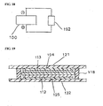
- a stack 100 is formed by preparing an electrolyte layer 120 in a bipolar electrode and stacking the electrolyte layers upon one another.
- the bipolar electrode has an anode 112, a cathode 113 and a collector 111.
- the cathode 113 is arranged at one side surface of the collector 111, and the anode 112 is arranged at another side surface of the collector 111. That is, the collector 111 is placed between the cathode 113 and the anode 112.
- the electrolyte layer 120 has a layer comprising separators 121 and 122, which are stacked upon one another (two sheets), and a layer of electrolyte between the separators 121 and 122 and the cathode 113 or the anode 112.
- the separators 121 and 122 are porous membranes having permeability for segmenting the cathode 113 or the anode 112, wherein the electrolyte can penetrate into such membranes.
- the electrolyte can be, for example, a polymer gel electrolyte (gel polymer-based electrolyte).
- separators 121 and 122 are stacked upon one another in the electrolyte layer 120, although a bubble remains in the electrolyte at the cathode or anode side of the bipolar electrode, it is easy to exhaust such a bubble via the separators 121 and 122.
- the separators 121 and 122 have permeability such that the electrolyte can penetrate therein from an opposite side surface of the cathode 113 or anode 112. Further, it is also easy to exhaust the bubble from a space between the separators 121 and 122.
- the cathode or anode side exists at one side surface of the separators 121 and 122 in the electrolyte layer 120 of the stack 100, while the separators 121 and 122 exist at another side surface. Accordingly, it is easy to exhaust the remaining bubble from one side surface to another side surface of the separators 121 and 122. It is further easy to exhaust the remaining bubble from a space between the separators 121 and 122.
- the bipolar battery 10 also has first and second sealing layers 115 and 117.
- the first sealing layer 115 is arranged at one side surface of the collector 111 and extended to surround an end of the cathode 113.
- the electrolyte layer 120 is arranged to cover the cathode 113 and the first sealing layer 115.
- the second sealing layer 117 is position-adjusted with the first sealing layer 115, thereby being arranged at another side surface of the collector 111 and extended to surround an end of the anode 112.
- a region wherein the first and second sealing layers 115 and 117 are arranged is referred to as a charging portion.
- the collector 111 is, for example, a stainless steel foil.
- the collector 111 is certainly not limited thereto and may include an aluminum foil, a clad material of nickel and aluminum, a clad material of copper and aluminum, or a plating material of a combination of the these metals.
- An anode active material of the anode 112 is, for example, a hard carbon (a non-graphitized carbon material).
- the anode active material is certainly not limited thereto since it may include a graphite-based carbon material or a lithium-transition metallic composite oxide.
- the anode active material composed of carbon and the lithium-transition metallic composite oxide is advantageous in terms of capacity and power.
- a cathode active material of the cathode 113 is, for example, LiMn 2 O 4 , although it is certainly not limited thereto.
- the lithium-transition metallic composite oxide is desirable in terms of capacity and power.
- Thicknesses of the cathode 113 and anode 112 may be set depending on the purpose of use (e.g., emphasis on power or energy) or ion conductivity.
- a charging material constituting the first and second sealing layers 115 and 117 is, for example, one-liquid uncured epoxy resin.
- the charging material is not limited thereto and may include other thermosetting resins (polypropylene or polyethylene) or thermoplastic resins. In certain embodiments, it is beneficial to select a material having a desired sealing effect depending on the type of application.
- a material for each separator 121, 122 in this embodiment can be porous PE (polyethylene) having permeability such that the electrolyte can penetrate into the separator.
- the material may include other polyolefins such as PP (polypropylene), a stack in a three-layer structure of PP/PE/PP, polyamide, polyimide, aramide or non-woven fabric.
- the non-woven fabric includes, for example, cotton, rayon, acetate, nylon or polyester.
- a host polymer of the electrolyte is, for example, PVDF-HFP (copolymer of polyvinylidene fluoride and hexafluoropropylene) containing 10% of HFP (hexafluoropropylene) copolymer.
- the host polymer is not limited thereto and may include other polymers without lithium ion conductivity or polymer (solid polymer electrolyte) with ion conductivity.
- Other polymers without lithium ion conductivity for example, include PAN (polyacrylonitile) and PMMA (polymethylmethacrylate).
- a polymer with ion conductivity for example, is PEO (polyethylene oxide) or PPO (polypropylene oxide).
- An electrolytic solution retained in the host polymer includes, for example, an organic solvent composed of PC (propylene carbonate) and EC (ethylene carbonate), and lithium salt (LiPF 6 ) as a support salt.
- the organic solvent is not limited to PC and EC since it may include other ring-type carbonate classes, chain-type carbonate classes such as dimethylcarbonate and ether classes such as tetrahydrofuran.
- the lithium salt can alternatively include other inorganic anionic salts and organic anionic salts such as LiCF 3 SO 3 instead of LiPF 6 .
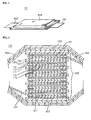
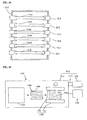
- the bipolar battery 10 is housed within an exterior case 104 in the form of a stack 100 of a unit bipolar battery, thereby preventing an impact from the outside or environmental deterioration.
- Terminal leads 101 and 102 composed of a high conductive member are connected to respective collectors 111 placed at the outermost layer of the stack 100.
- the high conductive member includes, for example, aluminum, copper, titan, nickel, stainless or alloys thereof.
- the reference number 103 indicates a reinforcing plate.
- the terminal leads 101 and 102 extend to an outer portion of the exterior case 104, and each serves as an electrode tab for extracting the current from the stack 100. Further, by arranging an electrode tab of an independent separate member and connecting to the terminal leads 101 and 102 directly or by using a lead, it is possible to extract the current from the stack 100.
- the exterior case 104 can be composed of a sheet material such as polymer-metallic composite laminate film wherein metals such as aluminum, stainless, nickel or copper (including alloys thereof) are coated by an insulator such as a polypropylene film. Further, the exterior case 104 is formed by bonding a part or the entire outer periphery of the case via thermal fusion.
- the bipolar battery 10 is possible to use independently.
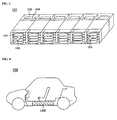
- the bipolar battery 10 in the form of a battery assembly 130 as shown in FIG. 3 .
- the battery assembly 130 is constituted by serializing and/or parallelizing the bipolar battery 10 and multi-connecting the bipolar batteries 10.
- the battery assembly 130 has conductive bars 132 and 134.
- the conductive bars 132 and 134 are connected to the terminal leads 101 and 102 extended from an inner portion of the bipolar battery 10.
- a connecting method includes, for example, an ultrasonic welding operation, a thermal welding operation, a laser welding operation, a rivet operation, a caulking operation or an electronic beam.
- the battery assembly module 136 By serializing and/or parallelizing and multi-connecting the battery assemblies 130, it is possible to provide a battery assembly module (a large scale battery assembly) 136 as shown in FIG. 4 . Since the battery assembly module 136 can secure a higher power, it is possible, for example, to be mounted as a power source for driving a motor of a vehicle 138.
- the vehicle includes, for example, an electric vehicle, a hybrid electric vehicle or an electric train.
- the battery assembly module 136 can perform very elaborate control such as performing a control of charging in every interior bipolar battery 10 or every battery assembly 130. Accordingly, it is possible to achieve functional improvements such as an extension of driving distance per charging at one time or an extension of lifetime of a battery mounted on a vehicle.
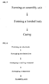
- FIG. 5 is a flow diagram of a method for manufacturing a bipolar battery in accordance with the first embodiment.
- the method includes a step of forming an assembly unit as a sub-assembly unit wherein the electrolyte and the separator are sequentially arranged at both sides of the bipolar electrode, a step of forming a bonded body as an assembly step for forming the stack (bonded body) wherein the assembly units (sub-assembly units) are stacked and integrated and a step of assembling for housing the integrated stack within the exterior case.
- Forming the bonded body comprises a stacking step for stacking the bipolar batteries upon one another by interposing the electrolyte layer, as will be explained below.
- the stacking step since the separators are overlapped with each other wherein the electrolytes can penetrate, it becomes easy to exhaust such a bubble left at the cathode or anode side of the bipolar electrode from a surface opposite to the cathode or anode side via the separator, which has a property for the electrolytes to penetrate therein. Further, it is also easy to exhaust the bubble from a space between the separators.
- FIG. 6 is a flow diagram of the process for forming the assembly unit shown in FIG. 5 .
- FIG. 7 is a plan view of the process for forming the electrode shown in FIG. 6
- FIG. 8 is a cross-sectional view of the process for forming the electrode shown in FIG. 6 .
- FIG. 9 is a cross-sectional view of the process for arranging the electrolyte shown in FIG. 6
- FIG. 10 is a plan view of the process for arranging the sealing material shown in FIG. 6 .
- FIG. 11 is a cross-sectional view of the process for arranging the sealing material shown in FIG. 6 .
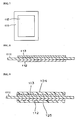
- FIG. 12A is a cross-sectional view of the process for arranging the separator shown in FIG. 6 and the assembly unit 108 as a sub-assembly.
- the process of forming an assembly unit can include the steps of forming the electrode, arranging the electrolyte, arranging the sealing material and arranging the separator.
- cathode slurry is first adjusted in the process of forming the electrode.
- the cathode slurry is prepared, for example, to have a cathode active material of 85 wt%, a conductive auxiliary agent of 5 wt% and a binder of 10 wt%.
- the cathode slurry obtains a desired viscosity by adding a viscosity adjusting solvent therein.
- the cathode active material is, for example, LiMn 2 O 4
- the conductive auxiliary agent is acetylene black.
- the binder is PVDF (polyvinylidene fluoride).
- the viscosity adjusting solvent is NMP (N-methyl-2-pyrolidone).
- the cathode slurry is applied to one side surface of the collector 111 composed of stainless steel foil.
- the conductive auxiliary agent may include carbon black or graphite.
- the binder and the viscosity adjusting solvent are not limited to PVDF and NMP.
- anode slurry is adjusted.
- the anode slurry is prepared, for example, to have an anode active material of 90 wt% and a binder of 10 wt%.
- the anode slurry obtains a desired viscosity by adding a viscosity adjusting solvent therein.
- the anode slurry is applied to another side surface of the collector 111.
- the anode active material is hard carbon
- the binder and the viscosity adjusting solvent are PVDF and NMP.
- the anode slurry is applied to another side surface of the collector 1 11.
- Applied membranes of the cathode slurry and the anode slurry are, for example, dried by using a vacuum oven and respectively form the cathode 113 composed of the cathode active material and the anode 112 composed of the anode active material (see FIGS. 7 and 8 ). At this time, NMP is removed by being volatilized.
- Thicknesses of the cathode 113 and the anode 112 are certainly not limited and may be set depending on the purpose of use (e.g., emphasis on power or energy) or ion conductivity.
- the electrolytes 124 and 125 are applied to an electrode portion of the cathode 113 and the anode 112, respectively (see FIG. 9 ).
- the electrolytes 124 and 125 are prepared, for example, to have electrolytic solution of 90 wt% and host polymer of 10 wt%. Electrolytes 124 and 125 obtain a viscosity suitable for applying by adding a viscosity adjusting solvent therein.
- the electrolytic solution includes an organic solvent composed of PC (propylene carbonate) and EC (ethylene carbonate) and lithium salt (LiPF 6 ) as a support salt.
- concentration of the lithium salt is, for example, 1 M.
- the host polymer is, for example, PVDF-HFP (copolymer of polyvinylidene fluoride and hexafluoropropylene) containing 10% of HFP (hexafluoropropylene) copolymer.
- a viscosity preparing solvent is DMC (dimethyl carbonate). The viscosity preparing solvent is not limited to DMC.
- a first sealing material 114 is first arranged so as to extend an outer periphery in the cathode side wherein the collector 111 is exposed as well as an edge of the cathode 113.
- an application is made using a dispenser, for example.
- a second sealing material 116 is arranged to extend an outer periphery in the anode side wherein the collector 111 is exposed as well as an edge of the anode 112. At this time, the second sealing material 116 is positioned so as to be opposite (and overlapped) to the first sealing material 114.
- the first and second sealing materials are charging materials composed of a one-liquid uncured epoxy resin in this example.
- the separators 121 and 122 are arranged so as to cover both the cathode side surface and the anode side surface of the collector 111.
- the assembly unit 108 is formed wherein the electrolytes 124 and 125 and the separators 121 and 122 are sequentially arranged at both sides of the bipolar electrode.
- the separators 121 and 122 are porous PE.
- the assembly unit 108 since the assembly unit 108 is arranged so as to cover both the cathode and anode side surfaces of the collector 111, the assembly unit 108 becomes a sub-assembly component packed by a separator such as PE without exposing the electrode and electrolyte. To this end, delivery becomes easy without altering or deteriorating the electrode and electrolyte. Further, since the sub-assembly components are stacked upon one another in the following process, a stacking operation becomes very easy.
- the assembly unit (sub-assembly) 108 can be housed in a vacuum container or suctioned from the edges of the separators at both sides by using a vacuum cup. Since the bubble can be exhausted from the electrolytes 124 and 125 at both sides of the bipolar electrode via the separators 121 and 122 having permeability at this time, the remaining bubble can be further limited in addition to exhausting the bubble after forming the stack 100, as is explained next.
- a charging portion is formed in a space between the collector 111 and the electrolyte layer 120.
- the charging material is arranged in the charging portion so as to surround the edges of the cathode 113 and the anode 112.
- a thickness of the first sealing material 114 is predetermined to be less than a total thickness of the cathode 113 and electrolyte 124.
- a thickness of the second sealing material 116 is predetermined to be less than a total thickness of the anode 112 and electrolyte 125. Since the separators 121 and 122 contact a center portion wherein the electrolytes 124 and 125 are arranged prior to contacting the first and second sealing materials 114 and 116 arranged in the outer periphery, the remaining bubble in the inner portion surrounded by the first and second sealing materials 114 and 116 is limited.
- FIG. 12B is a cross-sectional view when the assembly unit 108 shown in FIG. 12A is partially stacked in the process of forming the bonded body shown in FIG. 5 .
- FIG. 13 is a flow diagram of forming the bonded body (assembly process) shown in FIG. 5
- FIG. 14 is a cross-sectional view of a process for setting the assembly unit shown in FIG. 13 .
- FIG. 15 is a diagram of a process for stacking the assembly unit and for pressing shown in FIG. 13 .
- FIG. 16 is a diagram of a process for forming a sealing layer shown in FIG. 13
- FIG. 17 is a diagram of a process for forming an interface shown in FIG. 13 .
- FIG. 18 is a diagram of a process for the initial charging shown in FIG. 13 .
- the process of forming the bonded body comprises the steps of setting and stacking the assembly unit, pressing and forming a sealing layer, forming an interface, initial charging and exhausting the bubble.
- the assembly units 108 (as a plurality of sub-assemblies) are sequentially set in a magazine 150.
- the separators 121 and 122 are arranged at the outer sides of the electrolytes 124 and 125 and the first and second sealing materials 114 and 116 wherein the electrolytes 124 and 125 are arranged at both sides of the bipolar electrode included in the assembly unit 108, the electrolytes 124 and 125 and the first and second sealing materials 114 and 116 are not exposed to the outside.
- the magazine 150 has a clamp mechanism 152, which is in a frame shape and is capable of embracing the outer peripheral portion of the assembly unit 108.
- the clamp mechanism 152 is arranged in a stacking direction with an interspacing such that the assembly units 108 do not contact each other.
- the stacking direction is vertical to a surface direction of the assembly unit 108.
- the clamp mechanism 152 is configured, for example, to have an elastic member composed of a spring and to be retainable and supportable when assigning a tensile force to the assembly unit 108 based on an elastic force such that corrugation is not generated.
- Other mechanisms to perform a clamping function are also possible. Since such mechanisms are known in the art, a detailed explanation thereof is omitted herein.
- the magazine 150 is arranged within a vacuum treatment device 160.
- the stack 100 of the assembly unit 108 is formed under vacuum with a range of, for example 0.2 to 0.5 ⁇ 10 5 Pa.
- the electrolytes 124 and 125 and the first and second sealing materials 114 and 116 included in the assembly unit (sub-assembly) 108 are covered by the separators 121 and 122, they are not exposed to the outside. To this end, it is easy to handle the assembly unit 108 to thereby secure the working properties. Further, since the separators 121 and 122 are merely overlapped with each other, it is easy to perform a stacking operation while limiting any remaining bubble. Also, since the separators are overlapped with each other, corrugation is hardly generated to thereby minimize the remaining bubble therefrom. Since the assembly unit 108 is under vacuum, the bubble is introduced into a stacking interface of the electrode and the electrolyte layer, passes through the separator and is efficiently exhausted from a space between the separators to the outside. This further reduces the remaining bubble.
- FIG. 12B is a cross-sectional view when a part of the assembly unit 108 is stacked in the process of forming the bonded body. Although the separators 121 and 122 are overlapped with each other, FIG. 12B shows the separators 121 and 122 with a space therebetween for the sake of convenience in order to easily explain the theory on how the bubble N is exhausted. As shown in FIG.
- the bubble N can be exhausted via the separators 121 and 122 even when arranged in the assembly unit 108.
- the bubble N can be exhausted from a space between the separators 121 and 122 at any process after stacking the assembly unit 108 such as pressing or forming an interface.
- the bubble N can be exhausted after being cased.
- a method of forming the stack 100 comprises, for example, sequentially releasing the clamp mechanism 152 for embracing the assembly unit 108 from a lower side so as to be stacked at a rest arranged at a lower portion of the magazine 150.
- the method is certainly not limited thereto.
- the rest may be moved from a lower side to an upper side of the magazine 150 to stack the stack 108 nearby without being exceedingly displaced.
- the magazine may be moved from the upper side to the lower side by fastening the rest.
- the vacuum treatment device 160 shown in FIG. 15 has an apparatus 162 for performing a vacuum function, an apparatus 170 for performing a pressing function and a controller 178.
- the vacuuming apparatus 162 has a vacuum chamber 163, a vacuum pump 164 and a piping system 165.
- the vacuum chamber 163 has a detachable (openable) cover portion and a fixed base wherein the magazine 150 and the pressing apparatus 170 are arranged.
- the vacuum pump 164 is, for example, centrifugal and is used for forming an inner portion of the vacuum chamber 163 in a vacuum state.
- the piping system 165 is used for connecting the vacuum pump 164 and the vacuum chamber 163, and a leak valve (not shown) is arranged therein.
- the pressing apparatus 170 has a base plate 171 and a press plate 173 spaced apart from the base plate 171.
- an elastic body in a sheet-shape may be arranged on the base plate 171 and the press plate 173.
- the controller 178 is used for controlling the movement or pressing force of the base plate 173.
- the controller 178 can be, for example, a microcomputer including a random access memory (RAM), a read-only memory (ROM) and a central processing unit (CPU) in addition to various input and output connections.
- the control functions are performed by execution by the CPU of one or more programs stored in ROM.
- the stack 100 is pressed by the press plate and the base plate 171 while maintaining a vacuum state.
- the first and second sealing materials 114 and 116 are prepared to form the desired thicknesses.
- the pressure used in this pressing is, for example, 1 to 2 ⁇ 10 6 Pa.
- the first and second sealing materials 114 and 116 included in the stack 100 may be thermally cured, thereby forming the first and second sealing layers 115 and 117.
- the heating condition is, for example, 80°C. Heating the stack can be performed other than in an oven.
- the desired thicknesses of the first and second sealing materials 114 and 116 in the process of pressing are set to reduce invading moisture by minimizing the thicknesses contacting the outer atmosphere of the first and second sealing layers 115 and 117.
- thermoplastic resin may be applied to the first and second sealing materials 114 and 116.
- first and second sealing materials 114 and 116 are plasticized by heating to form the first and second sealing layers 115 and 117.
- the electrolytes 124 and 125 penetrate into the separators 121 and 122 included in the stack 100 and a gel interface is formed thereon as seen in FIG. 17 .
- the heating and pressing conditions are, for example, 80°C and 1 to 2 ⁇ 10 6 Pa, respectively. By doing this heating and pressing, the assembly unit 108 is stacked so that an integrated stack (bonded body) 100 can be obtained.
- the bubble N is exhausted. Namely, the bubble N is exhausted from the electrolyte 124 via the separator 121, exhausted from the electrolyte 125 via the separator 122 and exhausted from a space between the separators 121 and 122 to the outside.
- the pressing apparatus 180 has a base plate 181, a press plate 183 close to but spaced apart from the base plate 181, a lower portion heating part 185, an upper portion heating part 187 and a controller 188.
- the lower portion heating part 185 and the upper portion heating part 187 have a resistance heating element, for example, and the two parts 185, 187 are arranged within the base plate 181 and the press plate 183 and are used to increase the temperature of the base plate 181 and the press plate 183.
- the controller 188 like the controller 178, is used for controlling the movement and pressing force of the press plate 183 and is also used for controlling the temperature of the lower portion heating part 185 and the upper portion heating part 187.
- either of the lower portion heating part 185 or the upper portion heating part 187 may be omitted.
- the lower portion heating part 185 and the upper portion heating part 187 may be arranged at an outer portion of the base plate 181 and the press plate 183.
- a sheet-shaped elastic body may be arranged in the base plate 181 and the press plate 183.
- the initial charging condition is, for example, a capacity base approximately calculated from an application weight of the cathode, such as 4 hours in 21 V-0.5 C.
- the bubble in a center portion of the stack 100 is moved to the outer periphery and is then removed by pressing a roller against a surface of the stack 100.
- the process of exhausting the bubble is not essential. However, it is possible to improve the power density of the battery by further limiting the bubble via such a process.
- the integrated stack (bonded body) 100 is housed within the exterior case 104 (see FIG. 2 ) to thereby manufacture the bipolar battery 10 (see FIGS. 1 and 2 ).
- the exterior case 104 is formed by arranging the stack 100 between two sheet-shaped exterior materials and bonding an outer periphery of the exterior materials.
- the exterior materials can be polymer-metallic composite laminate film coated by an insulator such as a polypropylene film and bonded by applying a thermal fusion.
- the process of forming the sealing layer and the process of forming the interface are integrated.
- the hardening of the first and second sealing materials 114 and 116 and the completing of the electrolyte layer are performed simultaneously. By doing so, it is possible to reduce the number of manufacturing processes.
- a process of attaching a tab (lead line) for monitoring a potential of each layer (bipolar unit battery) of the stack 100 may be added between the processes of forming the sealing layer and forming the interface.
- FIG. 19 is a cross-sectional view of a modified example, which is not part of the present invention.
- the first and second sealing materials 114 and 116 are arranged between the collector 111 and the separators 121 and 122 and extended to the ends of the cathode 113 and anode 112.
- a sealing material 118 is arranged so as to extend to the edges of the cathode 113, the collector 111 and the anode 112.
- the first embodiment can provide a bipolar battery that minimizes the introduction of a bubble and a method of manufacturing such a battery.
- the polymer gel electrolyte is a thermoplastic containing the electrolyte within a polymer framework, liquid leakage is prevented to thereby prevent liquid junction so as to constitute the bipolar battery having high reliability.
- the polymer gel electrolyte is certainly not limited to thermoplastic since it may be thermosetting. In such a case, the liquid leakage is prevented by hardening the electrolyte layer by pressing under heating to thereby prevent the liquid junction.
- the surface pressure in the processes of pressing and forming the interface is certainly not limited to 1 to 2 ⁇ 10 6 Pa since it may be appropriately established by considering the material properties such as the strength of materials of the stack 100.
- the heating temperature in the process of forming the sealing layer is not limited to 80 °C. It can, for example, be anywhere within a range between 60°C and 150°C when considering the material properties such as the heat resistance of the electrolytic solution or the hardening temperature of the first sealing material 114 (first sealing layer 115) and the second sealing material 116 (sealing layer 117).
- the electrolytes 124 and 124 are certainly not limited to the gel polymer class since they may include the electrolytic solution class.
- the electrolytic solution is applied to each electrode portion of the cathode 113 and anode 112 by using a micropipette and sank therein (see FIG. 9 )
- the electrolytic solution includes an organic solvent composed of propylene carbonate (PC) and ethylene carbonate (EC), a lithium salt (such as LiPF 6 ) as a support salt and a small quantity of surfactant.
- concentration of the lithium salt is, for example, 1 M.
- the organic solvent is certainly not limited to PC and PE since it may include other ring-type carbonate classes, chain-type carbonate classes such as dimethyl carbonate or ether classes such as tetrahyrdofuran.
- the lithium salt is also not limited to LiPF 6 since it may include other inorganic anionic salts and organic anionic salts such as LiCF 3 SO 3 .
- FIG. 20 is a flow diagram of a process for forming a bonded body in accordance with the second embodiment.
- FIG. 21 is a diagram of a process for penetrating a sealing material shown in FIG. 20 .
- the second embodiment differs from the first embodiment in that it comprises a process of penetration of a sealing material between the processes of pressing and forming the sealing layer.
- the pressing force is not sufficiently transferred to a portion (charging portion) wherein the first and second sealing materials are arranged in spite of pressing a stack 200. This causes a sealing shortage.
- the first and second sealing materials are sufficiently penetrated into the separator by adding a process of penetration of the sealing material in order to press the charging portion in the stack 200 by using a pressing device 280.
- the portion into which the first and second sealing materials are penetrated is heated so as to be thermally cured.
- the adhesive property of the first and second sealing layers is improved compared to the first embodiment.
- the first and second sealing materials penetrate into a portion of the separator of the manufactured bipolar battery opposite to the first and second sealing layers.
- the pressing device 280 has a base plate 281 in which the stack 200 is arranged, a press plate 283 close to but spaced apart from the base plate 281 and a controller similar to controllers 178 and 188 so not shown in FIG. 21 .
- the press plate 283 is divided to have a center press plate 284 and an outer periphery press plate 285.
- the center press plate 284 is used for supporting a portion of the stack 200 wherein an electrode portion (i.e., the cathode and anode) is arranged.
- the outer periphery press plate 285 is used for pressing a charging portion of the stack 200.
- the controller is used for controlling the movements or pressing force of the center press plate 284 and the outer periphery press plate 285. Therefore, the pressing device 280 is capable of pressing only the charging portion by using the outer periphery press plate 285 of the stack 200 arranged in the base plate 281.
- the pressing operation by the outer periphery press plate 285 occur after pressing the electrode portion of the stack 200 by the center press plate 284. In such a case, it is possible to move the bubble in the electrode portion to the outer peripheral portion, further minimizing the remaining bubble in the electrode portion.
- sealing properties are further improved. Further, it is possible to appropriately integrate the processes of pressing and penetrating the sealing material as necessary.
- FIG. 22 is a plan view of a process for arranging the sealing material in accordance with the third embodiment
- FIG. 23 is a conceptual view of a process for pressing in accordance with the third embodiment.
- the third embodiment differs from the first embodiment with respect to the processes of arranging the sealing material, stacking and pressing.
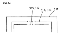
- first and second sealing materials 314 and 316 discontinuously extend to surround the cathode and anode.
- the notch-shaped gap portions 315 and 317 are formed where the first and second sealing materials 314 and 316 are not arranged. That is, the gap portion is formed in the charging portion.
- the reference number 311 indicates a collector.
- the process of stacking comprises a process of exhausting the bubble.
- the bubble remaining in an inner space surrounded by the collector, the electrolyte layer and the first and second sealing materials 314 and 316 is exhausted via the gap portions 315 and 317.
- the process of pressing comprises processes of exhausting the bubble and occluding the gap.
- the stack is pressed along a direction that the bipolar electrode is stacked by a press plate and a base plate, such as those previously described. At this time, a portion (charging portion) in the stack is pressed wherein the first and second sealing materials 314 and 316 are arranged.
- the bubble remaining in the inner space surrounded by the collector, the electrolyte layer and the first and second sealing materials 314 and 316 is exhausted via the gap portions 315 and 317.
- the first and second sealing materials 314 and 316 positioned around the gap portions 315 and 317 are directed toward the gap portions 315 and 317 by proceeding with the pressing operation as shown in FIG. 23 .
- the gap portions 315 and 317 are occluded by coating the gap portions 315 and 317, stopping the exhausting function.
- FIG. 24 is a plan view of a modified example constructed in accordance with the third embodiment.
- the end surfaces of the first and second sealing materials 314 and 316 around the gap portions 315 and 317 have an approximately circular shape.
- the distance between the gap portions 315 and 317 is not constant. That is, the flow capabilities of the first and second sealing materials are improved as the amount of the first and second sealing materials 314 and 316 is increased. Further, since there is a portion wherein a space between the gap portions 315 and 317 is narrowed, it is possible to easily occlude the gap portions 315 and 317.
- the introduction of the bubble can be further limited in the third embodiment.
- porous separators into which the electrolyte is penetrated are overlapped with each other in the first to third embodiments.
- the bubble remains at the cathode or anode side of the bipolar electrode, it is easy to exhaust such a bubble from a surface opposite to the cathode or anode side via the separator wherein the electrolyte can penetrate therein. Further, it is also easy to exhaust the bubble from a space between the separators.
- the separators are arranged at both sides of the cathode and anode.
- the separators are arranged at both sides of the cathode and anode to thereby form a unit. This is so that the unit can be stacked by being covered and retained by the separator without exposing the cathode, the anode and the electrolyte.
- corrugation is hardly generated in the separator, and the stacking operation becomes easy, facilitating mass production.
- the separators wherein the electrolyte can penetrate are overlapped with each other, although a redundant penetrating portion (i.e., micro-crack) is generated in a part of the separator, the cathode and anode are clearly segmented from each other due to the existence of the overlapped separators. Thus, the function of the separator is secured. Accordingly, productivity may be increased.
- a redundant penetrating portion i.e., micro-crack
- first to third embodiments illustrate examples of the separators wherein two separators are overlapped with each other.
- the invention is not limited thereto since it may include separators wherein three separators are overlapped with each other, for example. In such a case, it is advantageous to form the separators as thin as possible in view of the power density.
Landscapes
- Chemical & Material Sciences (AREA)
- Chemical Kinetics & Catalysis (AREA)
- Electrochemistry (AREA)
- General Chemical & Material Sciences (AREA)
- Engineering & Computer Science (AREA)
- Manufacturing & Machinery (AREA)
- Secondary Cells (AREA)
Claims (13)
- Verfahren zur Herstellung einer bipolaren Batterie (10), aufweisend:Bilden einer ersten und einer zweiten bipolaren Elektrode, die jeweils einen Kollektor (111), eine Kathode (113), die auf einer Seite des Kollektors (111) gebildet ist, und eine Anode (112), die auf einer gegenüber liegenden Seite des Kollektors (111) gebildet ist, aufweisen;Anordnen eines ersten und eines zweiten Separators (121, 122) auf gegenüber liegenden Seiten jeder bipolaren Elektrode, wobei jeder Separator eine ausreichende Durchlässigkeit für das Eindringen eines Elektrolyten hat;Anordnen einer ersten Elektrolytschicht (124) zwischen der Kathode (113) und dem ersten Separator (121) jeder bipolaren Elektrode und einer zweiten Elektrolytschicht (125) zwischen der Anode (112) und dem zweiten Separator (122) jeder bipolaren Elektrode;Anordnen einer ersten Dichtung (114) in jeder bipolaren Elektrode, so dass sie einen äußeren Umfang der Kathode (113) und der ersten Elektrolytschicht (124) umgibt, wobei eine Dicke der ersten Dichtung (114) so vorbestimmt ist, dass sie geringer als eine Gesamtdicke der Kathode (113) und der ersten Elektrolytschicht (124) ist,Anordnen einer zweiten Dichtung (116) in jeder biopolaren Elektrode, so dass sie einen äußeren Umfang der Anode (112) und der zweiten Elektrolytschicht (125) umgibt, wobei eine Dicke der zweiten Dichtung (116) so vorbestimmt ist, dass sie geringer als eine Gesamtdicke der Anode (112) und der zweiten Elektrolytschicht (125) ist; undStapeln unter Vakuum der ersten bipolaren Elektrode und der zweiten bipolaren Elektrode, die derart abgedichtet sind, so dass der erste Separator (121), der auf der ersten bipolaren Elektrode angeordnet ist, und der zweite Separator (122), der auf der zweiten bipolaren Elektrode angeordnet ist, miteinander in Kontakt stehen;dadurch gekennzeichnet, dass:die erste Dichtung (114) der ersten bipolaren Elektrode in einem Raum zwischen dem ersten Kollektor (111) und dem ersten Separator (121), die auf der ersten bipolaren Elektrode angeordnet sind, angeordnet ist;die zweite Dichtung (116) der ersten bipolaren Elektrode in einem Raum zwischen dem ersten Kollektor (111) und dem zweiten Separator (122), die auf der ersten bipolaren Elektrode angeordnet sind, angeordnet ist;die erste Dichtung (114) der zweiten bipolaren Elektrode in einem Raum zwischen dem zweiten Kollektor (111) und dem ersten Separator (121), die auf der zweiten bipolaren Elektrode angeordnet sind, angeordnet ist; unddie zweite Dichtung (116) der zweiten bipolaren Elektrode in einem Raum zwischen dem zweiten Kollektor (111) und dem zweiten Separator (122), die auf der zweiten bipolaren Elektrode angeordnet sind, angeordnet ist.
- Verfahren nach Anspruch 1, wobei das Stapeln der ersten bipolaren Elektrode und der zweiten bipolaren Elektrode das gegenseitige Überlappen des ersten Separators (121) der ersten bipolaren Elektrode und des zweiten Separators der zweiten bipolaren Elektrode umfasst.
- Verfahren nach Anspruch 1 oder Anspruch 2, wobei der Elektrolyt jeder der ersten und zweiten Elektrolytschichten (124, 125) einen Polymer-Gel-Elektrolyt oder eine elektrolytische Lösung aufweist.
- Verfahren nach Anspruch 3, wobei ein Spaltabschnitt (315, 317) innerhalb der ersten Dichtung (114) und der zweiten Dichtung (116) jeder bipolaren Elektrode gebildet ist und wobei das Verfahren das Entfernen einer Blase, die in einem Innenraum jeder bipolaren Elektrode verbleibt, der durch den Kollektor (111), mindestens einen der ersten und zweiten Separatoren (121, 122) und das Dichtungsmaterial der ersten Dichtung (114) und der zweiten Dichtung (116) gebildet ist, über den Spaltabschnitt (315, 317) aufweist.
- Verfahren nach Anspruch 4, aufweisend das Verschließen eines Spalts des Spaltabschnitts (315, 317) durch Pressen der ersten Dichtung (114) und der zweiten Dichtung (116) jeder bipolaren Elektrode entlang einer Stapelrichtung des Stapels nach Entfernen der Blase.
- Bipolare Batterie (10), aufweisend:eine erste und eine zweite bipolare Elektrode, die jeweils einen Kollektor (111), eine Anode (112), die auf einer Seite des Kollektors (111) gebildet ist, und eine Kathode (113), die auf der gegenüber liegenden Seite des Kollektors (111) gebildet ist, aufweisen;einen ersten und zweiten Separator (121, 122), die auf gegenüber liegenden Seiten jeder bipolaren Elektrode angeordnet sind, wobei jeder Separator (121, 122) eine ausreichende Durchlässigkeit für das Eindringen eines Elektrolyten hat;eine erste Elektrolytschicht (124) zwischen der Kathode (113) und dem ersten Separator (121) jeder bipolaren Elektrode und eine zweite Elektrolytschicht (125) zwischen der Anode (112) und dem zweiten Separator (122) jeder bipolaren Elektrode;für jede bipolare Elektrode eine erste Dichtung (114), die so angeordnet ist, dass sie einen äußeren Umfang der Kathode (113) und der ersten Elektrolytschicht (124) umgibt, wobei eine Dicke der ersten Dichtung (114) so vorbestimmt ist, dass sie geringer als eine Gesamtdicke der Kathode (113) und der ersten Elektrolytschicht (124) ist; undfür jede bipolare Elektrode eine zweite Dichtung (116), die so angeordnet ist, dass sie einen äußeren Umfang der Anode (112) und der zweiten Elektrolytschicht (125) umgibt, wobei eine Dicke der zweiten Dichtung (116) so vorbestimmt ist, dass sie geringer als eine Gesamtdicke der Anode (112) und der zweiten Elektrolytschicht (125) ist;wobei die erste bipolare Elektrode und die zweite bipolare Elektrode, die so abgedichtet sind, unter Vakuum gestapelt sind, so dass der erste Separator (121), der auf der ersten bipolaren Elektrode angeordnet ist, und der zweite Separator (122), der auf der zweiten bipolaren Elektrode angeordnet ist, miteinander in Kontakt stehen;dadurch gekennzeichnet, dass:die erste Dichtung (114) der ersten bipolaren Elektrode in einem Raum zwischen dem ersten Kollektor (111) und dem ersten Separator (121), die auf der ersten bipolaren Elektrode angeordnet sind, angeordnet ist;die zweite Dichtung (116) der ersten bipolaren Elektrode in einem Raum zwischen dem ersten Kollektor (111) und dem zweiten Separator (122), die auf der ersten bipolaren Elektrode angeordnet sind, angeordnet ist;die erste Dichtung (114) der zweiten bipolaren Elektrode in einem Raum zwischen dem zweiten Kollektor (111) und dem ersten Separator (121), die auf der zweiten bipolaren Elektrode angeordnet sind, angeordnet ist; unddie zweite Dichtung (116) der zweiten bipolaren Elektrode in einem Raum zwischen dem zweiten Kollektor (111) und dem zweiten Separator (122), die auf der zweiten bipolaren Elektrode angeordnet sind, angeordnet ist.
- Batterie (10) nach Anspruch 6, wobei der erste und zweite Separator (121, 122) jeder bipolaren Elektrode eine poröse Membran aufweisen, die eine Kathode der ersten bipolaren Elektrode und eine Anode der zweiten benachbarten bipolaren Elektrode segmentiert.
- Batterie (10) nach Anspruch 6 oder 7, wobei der Separator (121) der ersten bipolaren Elektrode und der zweite Separator (122) der zweiten bipolaren Elektrode überlappen.
- Batterie (10) nach Anspruch 8, wobei jede von der ersten und zweiten Elektrolytschicht (124, 125) einen Polymergelelektrolyten oder eine elektrolytische Lösung aufweist.
- Batterie (10) nach Anspruch 9, wobei ein Spaltabschnitt (315, 317) innerhalb der ersten Dichtung (114) und der zweiten Dichtung (116) jeder bipolaren Elektrode gebildet ist.
- Batterie (10) nach Anspruch 10, wobei der Spaltabschnitt (315, 317) während der Bildung des Stapels verschlossen ist.
- Batterie (10) nach Anspruch 8 oder Anspruch 9, wobei jede der ersten und zweiten Elektrolytschichten (124, 125) einen Polymergelelektrolyten aufweist.
- Batterieanordnung (130) oder ein Fahrzeug mit mehreren Batterien (10) nach einem der Ansprüche 6 bis 12.
Applications Claiming Priority (2)
| Application Number | Priority Date | Filing Date | Title |
|---|---|---|---|
| JP2006324678 | 2006-11-30 | ||
| JP2007260223A JP5157354B2 (ja) | 2006-11-30 | 2007-10-03 | バイポーラ電池およびその製造方法 |
Publications (2)
| Publication Number | Publication Date |
|---|---|
| EP1936730A1 EP1936730A1 (de) | 2008-06-25 |
| EP1936730B1 true EP1936730B1 (de) | 2013-02-20 |
Family
ID=39156154
Family Applications (1)
| Application Number | Title | Priority Date | Filing Date |
|---|---|---|---|
| EP07121749A Ceased EP1936730B1 (de) | 2006-11-30 | 2007-11-28 | Bipolarer Batteriestapel mit übereinander liegenden Separatoren und zugehöriges Herstellungsverfahren |
Country Status (2)
| Country | Link |
|---|---|
| US (1) | US7807295B2 (de) |
| EP (1) | EP1936730B1 (de) |
Families Citing this family (15)
| Publication number | Priority date | Publication date | Assignee | Title |
|---|---|---|---|---|
| US8148010B2 (en) * | 2006-11-30 | 2012-04-03 | Nissan Motor Co., Ltd. | Bipolar battery and battery assembly |
| EP1930977B1 (de) * | 2006-12-08 | 2012-05-30 | Nissan Motor Co., Ltd. | Bipolare Batterie und derer Herstellungsverfahren |
| JP5552731B2 (ja) * | 2007-10-25 | 2014-07-16 | 日産自動車株式会社 | 双極型電池の製造方法、および双極型電池 |
| WO2009078860A1 (en) | 2007-12-17 | 2009-06-25 | Utc Power Corporation | Heat treat configuration for porous carbon-carbon composites |
| JP5381078B2 (ja) * | 2008-12-19 | 2014-01-08 | 日産自動車株式会社 | 電極およびその製造方法 |
| US8163421B2 (en) * | 2009-03-09 | 2012-04-24 | Tsun-Yu Chang | High durability lithium-ion cells |
| MX342829B (es) * | 2010-03-05 | 2016-10-13 | Aic Blab Company * | Baterias de plomo y acido reguladas por valvula, bipolares, de peso ligero y metodos de las mismas. |
| JP5701688B2 (ja) * | 2011-01-31 | 2015-04-15 | 三洋電機株式会社 | 積層式電池およびその製造方法 |
| US10615393B2 (en) * | 2011-10-24 | 2020-04-07 | Advanced Battery Concepts, LLC | Bipolar battery assembly |
| US10446822B2 (en) | 2011-10-24 | 2019-10-15 | Advanced Battery Concepts, LLC | Bipolar battery assembly |
| US10096806B2 (en) | 2013-07-30 | 2018-10-09 | Johnson Controls Technology Company | System and method for clamping interconnection of battery cells |
| CN104577132B (zh) * | 2013-10-17 | 2016-11-16 | 北京好风光储能技术有限公司 | 一种双极性集流体及其制备方法 |
| JP6915567B2 (ja) * | 2018-02-28 | 2021-08-04 | 株式会社豊田自動織機 | 蓄電モジュール |
| JP7085390B2 (ja) * | 2018-04-09 | 2022-06-16 | 日産自動車株式会社 | 電池の製造方法 |
| US11619604B2 (en) | 2021-05-14 | 2023-04-04 | Sandisk Technologies Llc | Bipolar electrode bubble detection method and apparatus |
Family Cites Families (10)
| Publication number | Priority date | Publication date | Assignee | Title |
|---|---|---|---|---|
| US2942053A (en) | 1956-07-10 | 1960-06-21 | Electric Storage Battery Co | Electric battery |
| DK156859C (da) | 1984-06-20 | 1990-02-26 | Energiforskning Lab | Elektrode til et primaert eller sekundaert elektrisk batteri, elektrisk batteri omfattende saadanne elektroder samt fremgangsmaade til fremstilling af en saadan elektrode |
| US4874681A (en) | 1988-04-14 | 1989-10-17 | Rippel Wally E | Woven-grid sealed quasi-bipolar lead-acid battery construction and fabricating method |
| US5734363A (en) | 1995-07-14 | 1998-03-31 | Northern Telecom Limited | Method and apparatus for producing shading on a flat panel display |
| US5916515A (en) | 1997-02-27 | 1999-06-29 | Valence Technology, Inc. | Two-stage lamination process |
| JPH11204136A (ja) | 1998-01-08 | 1999-07-30 | Toyota Motor Corp | バイポーラ型リチウムイオン2次電池及びその製造方法 |
| US5902697A (en) | 1998-05-15 | 1999-05-11 | Valence Technology, Inc. | Bi-cell separation for improved safety |
| JP4178926B2 (ja) | 2002-11-29 | 2008-11-12 | 日産自動車株式会社 | バイポーラ電池、バイポーラ電池の製造方法、組電池および車両 |
| JP4367235B2 (ja) | 2004-05-28 | 2009-11-18 | 日産自動車株式会社 | バイポーラ電池、組電池、およびこれらを搭載した車両 |
| JP4876920B2 (ja) | 2004-12-10 | 2012-02-15 | 日産自動車株式会社 | バイポーラ電池 |
-
2007
- 2007-11-07 US US11/936,159 patent/US7807295B2/en active Active
- 2007-11-28 EP EP07121749A patent/EP1936730B1/de not_active Ceased
Also Published As
| Publication number | Publication date |
|---|---|
| US7807295B2 (en) | 2010-10-05 |
| US20080131775A1 (en) | 2008-06-05 |
| EP1936730A1 (de) | 2008-06-25 |
Similar Documents
| Publication | Publication Date | Title |
|---|---|---|
| EP1936730B1 (de) | Bipolarer Batteriestapel mit übereinander liegenden Separatoren und zugehöriges Herstellungsverfahren | |
| KR100987849B1 (ko) | 바이폴라 전지 및 그 제조 방법 | |
| US8404002B2 (en) | Bipolar battery and method of manufacturing same | |
| US7709146B2 (en) | Bipolar battery and method of manufacturing the same | |
| EP2503635B1 (de) | Anordnung aus einem bipolaren elektrodenpaar und einer trennmembran, bipolare batterie damit sowie herstellungsverfahren dafür | |
| EP2056378B1 (de) | Bipolare Sekundärbatterie, Batterieanordnung durch Verbinden der Batterien und Fahrzeug damit | |
| CN101425600B (zh) | 双极型二次电池、电池组及安装了这些电池的车辆 | |
| JP4876920B2 (ja) | バイポーラ電池 | |
| JP3615491B2 (ja) | 非水電解質二次電池およびその製造法 | |
| JP5552731B2 (ja) | 双極型電池の製造方法、および双極型電池 | |
| JP2004253168A (ja) | バイポーラ電池 | |
| JP5028812B2 (ja) | 電池モジュール | |
| JP2005174691A (ja) | バイポーラ電池 | |
| JP4670275B2 (ja) | バイポーラ電池および組電池 | |
| JP2010238425A (ja) | 電池の製造方法および製造装置 | |
| JP5261883B2 (ja) | 双極型二次電池 | |
| JP2005174844A (ja) | バイポーラ電池 | |
| JP7278989B2 (ja) | 非水二次電池及び非水二次電池の製造方法 | |
| JP2010238424A (ja) | 双極型二次電池の製造方法および製造装置 | |
| JP2005310667A (ja) | バイポーラ電池、バイポーラ電池の製造方法、組電池およびこれらを搭載した車両 | |
| JP5181422B2 (ja) | 双極型二次電池 | |
| JP5205749B2 (ja) | バイポーラ電池の製造方法 |
Legal Events
| Date | Code | Title | Description |
|---|---|---|---|
| PUAI | Public reference made under article 153(3) epc to a published international application that has entered the european phase |
Free format text: ORIGINAL CODE: 0009012 |
|
| AK | Designated contracting states |
Kind code of ref document: A1 Designated state(s): AT BE BG CH CY CZ DE DK EE ES FI FR GB GR HU IE IS IT LI LT LU LV MC MT NL PL PT RO SE SI SK TR |
|
| AX | Request for extension of the european patent |
Extension state: AL BA HR MK RS |
|
| 17P | Request for examination filed |
Effective date: 20081229 |
|
| AKX | Designation fees paid |
Designated state(s): DE FR GB |
|
| 17Q | First examination report despatched |
Effective date: 20090209 |
|
| REG | Reference to a national code |
Ref country code: DE Ref legal event code: R079 Ref document number: 602007028521 Country of ref document: DE Free format text: PREVIOUS MAIN CLASS: H01M0010040000 Ipc: H01M0010058500 |
|
| RIC1 | Information provided on ipc code assigned before grant |
Ipc: H01M 10/04 20060101ALI20120913BHEP Ipc: H01M 10/0525 20100101ALI20120913BHEP Ipc: H01M 2/08 20060101ALI20120913BHEP Ipc: H01M 10/0585 20100101AFI20120913BHEP Ipc: H01M 2/16 20060101ALN20120913BHEP |
|
| GRAP | Despatch of communication of intention to grant a patent |
Free format text: ORIGINAL CODE: EPIDOSNIGR1 |
|
| GRAS | Grant fee paid |
Free format text: ORIGINAL CODE: EPIDOSNIGR3 |
|
| GRAA | (expected) grant |
Free format text: ORIGINAL CODE: 0009210 |
|
| AK | Designated contracting states |
Kind code of ref document: B1 Designated state(s): DE FR GB |
|
| REG | Reference to a national code |
Ref country code: GB Ref legal event code: FG4D |
|
| REG | Reference to a national code |
Ref country code: DE Ref legal event code: R096 Ref document number: 602007028521 Country of ref document: DE Effective date: 20130418 |
|
| PLBE | No opposition filed within time limit |
Free format text: ORIGINAL CODE: 0009261 |
|
| STAA | Information on the status of an ep patent application or granted ep patent |
Free format text: STATUS: NO OPPOSITION FILED WITHIN TIME LIMIT |
|
| 26N | No opposition filed |
Effective date: 20131121 |
|
| REG | Reference to a national code |
Ref country code: DE Ref legal event code: R097 Ref document number: 602007028521 Country of ref document: DE Effective date: 20131121 |
|
| REG | Reference to a national code |
Ref country code: FR Ref legal event code: PLFP Year of fee payment: 9 |
|
| REG | Reference to a national code |
Ref country code: FR Ref legal event code: PLFP Year of fee payment: 10 |
|
| REG | Reference to a national code |
Ref country code: FR Ref legal event code: PLFP Year of fee payment: 11 |
|
| REG | Reference to a national code |
Ref country code: FR Ref legal event code: PLFP Year of fee payment: 12 |
|
| REG | Reference to a national code |
Ref country code: DE Ref legal event code: R084 Ref document number: 602007028521 Country of ref document: DE |
|
| REG | Reference to a national code |
Ref country code: GB Ref legal event code: 746 Effective date: 20231002 |
|
| PGFP | Annual fee paid to national office [announced via postgrant information from national office to epo] |
Ref country code: GB Payment date: 20231019 Year of fee payment: 17 |
|
| PGFP | Annual fee paid to national office [announced via postgrant information from national office to epo] |
Ref country code: FR Payment date: 20231019 Year of fee payment: 17 Ref country code: DE Payment date: 20231019 Year of fee payment: 17 |
|
| REG | Reference to a national code |
Ref country code: DE Ref legal event code: R119 Ref document number: 602007028521 Country of ref document: DE |
|
| GBPC | Gb: european patent ceased through non-payment of renewal fee |
Effective date: 20241128 |
|
| PG25 | Lapsed in a contracting state [announced via postgrant information from national office to epo] |
Ref country code: DE Free format text: LAPSE BECAUSE OF NON-PAYMENT OF DUE FEES Effective date: 20250603 |
|
| PG25 | Lapsed in a contracting state [announced via postgrant information from national office to epo] |
Ref country code: GB Free format text: LAPSE BECAUSE OF NON-PAYMENT OF DUE FEES Effective date: 20241128 |
|
| PG25 | Lapsed in a contracting state [announced via postgrant information from national office to epo] |
Ref country code: FR Free format text: LAPSE BECAUSE OF NON-PAYMENT OF DUE FEES Effective date: 20241130 |