EP1936200B1 - Pompe à vide à palettes étanchéifiée à l'aide de lubrifiants - Google Patents
Pompe à vide à palettes étanchéifiée à l'aide de lubrifiants Download PDFInfo
- Publication number
- EP1936200B1 EP1936200B1 EP07022562A EP07022562A EP1936200B1 EP 1936200 B1 EP1936200 B1 EP 1936200B1 EP 07022562 A EP07022562 A EP 07022562A EP 07022562 A EP07022562 A EP 07022562A EP 1936200 B1 EP1936200 B1 EP 1936200B1
- Authority
- EP
- European Patent Office
- Prior art keywords
- lubricant
- pump
- shaft
- vacuum pump
- rotary vane
- Prior art date
- Legal status (The legal status is an assumption and is not a legal conclusion. Google has not performed a legal analysis and makes no representation as to the accuracy of the status listed.)
- Revoked
Links
Images

Classifications
-
- F—MECHANICAL ENGINEERING; LIGHTING; HEATING; WEAPONS; BLASTING
- F04—POSITIVE - DISPLACEMENT MACHINES FOR LIQUIDS; PUMPS FOR LIQUIDS OR ELASTIC FLUIDS
- F04C—ROTARY-PISTON, OR OSCILLATING-PISTON, POSITIVE-DISPLACEMENT MACHINES FOR LIQUIDS; ROTARY-PISTON, OR OSCILLATING-PISTON, POSITIVE-DISPLACEMENT PUMPS
- F04C11/00—Combinations of two or more machines or pumps, each being of rotary-piston or oscillating-piston type; Pumping installations
- F04C11/001—Combinations of two or more machines or pumps, each being of rotary-piston or oscillating-piston type; Pumping installations of similar working principle
-
- F—MECHANICAL ENGINEERING; LIGHTING; HEATING; WEAPONS; BLASTING
- F04—POSITIVE - DISPLACEMENT MACHINES FOR LIQUIDS; PUMPS FOR LIQUIDS OR ELASTIC FLUIDS
- F04C—ROTARY-PISTON, OR OSCILLATING-PISTON, POSITIVE-DISPLACEMENT MACHINES FOR LIQUIDS; ROTARY-PISTON, OR OSCILLATING-PISTON, POSITIVE-DISPLACEMENT PUMPS
- F04C18/00—Rotary-piston pumps specially adapted for elastic fluids
- F04C18/30—Rotary-piston pumps specially adapted for elastic fluids having the characteristics covered by two or more of groups F04C18/02, F04C18/08, F04C18/22, F04C18/24, F04C18/48, or having the characteristics covered by one of these groups together with some other type of movement between co-operating members
- F04C18/34—Rotary-piston pumps specially adapted for elastic fluids having the characteristics covered by two or more of groups F04C18/02, F04C18/08, F04C18/22, F04C18/24, F04C18/48, or having the characteristics covered by one of these groups together with some other type of movement between co-operating members having the movement defined in group F04C18/08 or F04C18/22 and relative reciprocation between the co-operating members
- F04C18/344—Rotary-piston pumps specially adapted for elastic fluids having the characteristics covered by two or more of groups F04C18/02, F04C18/08, F04C18/22, F04C18/24, F04C18/48, or having the characteristics covered by one of these groups together with some other type of movement between co-operating members having the movement defined in group F04C18/08 or F04C18/22 and relative reciprocation between the co-operating members with vanes reciprocating with respect to the inner member
- F04C18/3441—Rotary-piston pumps specially adapted for elastic fluids having the characteristics covered by two or more of groups F04C18/02, F04C18/08, F04C18/22, F04C18/24, F04C18/48, or having the characteristics covered by one of these groups together with some other type of movement between co-operating members having the movement defined in group F04C18/08 or F04C18/22 and relative reciprocation between the co-operating members with vanes reciprocating with respect to the inner member the inner and outer member being in contact along one line or continuous surface substantially parallel to the axis of rotation
- F04C18/3442—Rotary-piston pumps specially adapted for elastic fluids having the characteristics covered by two or more of groups F04C18/02, F04C18/08, F04C18/22, F04C18/24, F04C18/48, or having the characteristics covered by one of these groups together with some other type of movement between co-operating members having the movement defined in group F04C18/08 or F04C18/22 and relative reciprocation between the co-operating members with vanes reciprocating with respect to the inner member the inner and outer member being in contact along one line or continuous surface substantially parallel to the axis of rotation the surfaces of the inner and outer member, forming the inlet and outlet opening
-
- F—MECHANICAL ENGINEERING; LIGHTING; HEATING; WEAPONS; BLASTING
- F04—POSITIVE - DISPLACEMENT MACHINES FOR LIQUIDS; PUMPS FOR LIQUIDS OR ELASTIC FLUIDS
- F04C—ROTARY-PISTON, OR OSCILLATING-PISTON, POSITIVE-DISPLACEMENT MACHINES FOR LIQUIDS; ROTARY-PISTON, OR OSCILLATING-PISTON, POSITIVE-DISPLACEMENT PUMPS
- F04C27/00—Sealing arrangements in rotary-piston pumps specially adapted for elastic fluids
- F04C27/02—Liquid sealing for high-vacuum pumps or for compressors
-
- F—MECHANICAL ENGINEERING; LIGHTING; HEATING; WEAPONS; BLASTING
- F04—POSITIVE - DISPLACEMENT MACHINES FOR LIQUIDS; PUMPS FOR LIQUIDS OR ELASTIC FLUIDS
- F04C—ROTARY-PISTON, OR OSCILLATING-PISTON, POSITIVE-DISPLACEMENT MACHINES FOR LIQUIDS; ROTARY-PISTON, OR OSCILLATING-PISTON, POSITIVE-DISPLACEMENT PUMPS
- F04C29/00—Component parts, details or accessories of pumps or pumping installations, not provided for in groups F04C18/00 - F04C28/00
- F04C29/0042—Driving elements, brakes, couplings, transmissions specially adapted for pumps
- F04C29/0085—Prime movers
-
- F—MECHANICAL ENGINEERING; LIGHTING; HEATING; WEAPONS; BLASTING
- F04—POSITIVE - DISPLACEMENT MACHINES FOR LIQUIDS; PUMPS FOR LIQUIDS OR ELASTIC FLUIDS
- F04C—ROTARY-PISTON, OR OSCILLATING-PISTON, POSITIVE-DISPLACEMENT MACHINES FOR LIQUIDS; ROTARY-PISTON, OR OSCILLATING-PISTON, POSITIVE-DISPLACEMENT PUMPS
- F04C29/00—Component parts, details or accessories of pumps or pumping installations, not provided for in groups F04C18/00 - F04C28/00
- F04C29/06—Silencing
Definitions
- the invention relates to a lubricant-sealed rotary vane vacuum pump with motor, a pump stage housing having pumping stage, safety valve, lubricant pump having inlet and outlet, the pump stage housing at least partially surrounding lubricant reservoir and hydraulic line, wherein the conveyed through the hydraulic line lubricant causes the opening of the safety valve.
- a rotary vane vacuum pump having the features of the preamble shows the DE-OS 10 2004 024 554 ,
- the lubricant in this pump is used, among other things, to open a hydraulically operated safety valve.
- the safety valve is only opened as long as a driven by the shaft of the vacuum pump lubricant pump sets the lubricant supplied to the safety valve under pressure.
- the lubricant also serves to lubricate the slide, which circulate in a cylindrical pump chamber and thus generate the pumping action. At the same time, the lubricant seals the gap between the slide, shaft and housing of the pump chamber.
- This housing, the pump stage housing is immersed in a so-called lubricant reservoir, therefore largely surrounded by lubricant. Heat generated within this pump stage housing is dissipated to the surrounding lubricant.
- the object of the invention is therefore to introduce a rotary vane vacuum pump whose structure prevents overheating of the lubricant.
- a channel branching between the outlet of the lubricant pump and the safety valve from the hydraulic line allows pressurized lubricant to flow into the lubricant reservoir.
- This flowing lubricant ensures that the lubricant in the lubricant reservoir does not behave statically but is in motion. In particular, this movement ensures that the pump stage housing contacting lubricant is conveyed away from this and passes to the pump housing surrounding the lubricant reservoir. There it can release the heat absorbed by the pump housing. Overheating of the lubricant is prevented in this way.
- the arrangement of a lubricant pump on the shaft between the motor and pumping stage according to a first embodiment of the invention shortens the length of the hydraulic line, since the safety valve is usually located in the vicinity of the engine.
- a lubricant flow resistance is arranged between the lubricant pump and the pumping stage. This reduces the amount of lubricant flowing into the pumping stage while it is under pressure.
- a sliding bearing for supporting the shaft is arranged between the lubricant pump and the pumping stage.
- the sliding bearing can be lubricated by emerging from the lubricant pump lubricant. This leaking lubricant is not the lubricant exiting through the actual lubricant pump outlet, but the lubricant leaking through the gaps between the housing and the shaft.
- Another advantage of this measure is therefore that a less good seal of the lubricant pump is sufficient, whereby their construction is considerably simplified and the réellet be lowered.
- the outlet of the lubricant pump is located on the side of the shaft facing a footprint of the rotary vane vacuum pump. With respect to the direction of gravity in the intended installation of the pump, this means that the outlet of the lubricant pump is arranged below the shaft centerline. This simplifies the ducting.
- the branching off of the hydraulic line channel opens at a height between the shaft center axis and a footprint of the rotary vane vacuum pump in the lubricant reservoir.
- This arrangement causes pressurized lubricant to flow in between the surface of the lubricant reservoir and the bottom. As a result, a turbulence of all areas of the lubricant reservoir is promoted and thus improves the heat exchange.
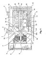
- the first figure shows a section along the shaft axis through a lubricant-sealed rotary vane vacuum pump, hereinafter referred to as vacuum pump.
- Gas enters the vacuum pump via a gas inlet 1, is compressed in its interior and expelled via a gas outlet 2.
- the safety valve 3 is arranged, which is hydraulically operated: The lubricant of the vacuum pump causes, as soon as it is under pressure, the opening of this safety valve.
- a gas guide 4 connects the safety valve to the suction chamber 11 of a first pumping stage 17, so that gas can pass from the gas inlet into the suction chamber as soon as the safety valve is opened.
- the pumping stage is arranged in a pump stage housing 10 which is at least partially surrounded by lubricant located in the lubricant reservoir 30.
- a slide 13 runs around.
- the circulation is created by the rotation of an eccentrically passing through the pumping chamber 11 shaft 15.
- Between slide and pump chamber creates a crescent-shaped space, which is periodically enlarged and reduced by the circulation of the slide, whereby the pumping action arises.
- the compressed gas is transferred via a transfer line 16 to the second pumping stage 18 and further compressed in the pump chamber 12, in the slide 14, further compressed and finally ejected.
- the shaft is driven by a motor.
- this motor comprises arranged on the shaft permanent magnets 8 and stationary coil 7, which generates a rotating magnetic field and thus sets the shaft in rotation.
- a separator 5 causes hermetic separation of the coils from the shaft.
- An electronic control unit 6 is connected via electrical lines to the coil and causes their energization.
- the invention can also be applied to vacuum pumps with other motors, for example asynchronous motors.
- the shaft is rotatably supported by a sliding bearing 35, which is arranged between the motor and pumping stage 17, and an end-side sliding bearing 36, which is provided at the shaft end, which lies on the side remote from the first pumping stage side of the second pumping stage 18.
- a lubricant pump is arranged between the engine and the first pumping stage.
- This comprises a slider 23 circulating in a lubricant scoop space 24, this rotation being effected by the rotation of the shaft 15.
- the cross section is shown here rectangular. For manufacturing it is advantageous to provide a circular cross-section.
- a lubricant flow resistance 34 is arranged between lubricant pump and pumping stage.
- the object of the lubricant flow resistance is to make the flow of pressurized lubricant leaving the lubricant pump in the direction of the pumping stage 17 more difficult. It does not need to be completely stopped because a small flow can be used to lubricate the slide bearing 35.
- this is formed as a step in the shaft, which is formed by a change in the shaft diameter.
- structures may be provided on the shaft surface, such as grooves. This idea can advantageously be further developed by providing a groove running around the shaft in such a way that a conveying effect is produced, which is directed counter to the direction of flow of the lubricant.
- the lubricant reservoir 30 serves to accommodate larger amounts of lubricant.
- This lubricant forms with that in pump rooms, Slide bearings and safety valve a circuit and is used for its replacement.
- the horizontal channel part 32a opens at the channel mouth 33 in this lubricant reservoir. From him lubricant exits, which is pressurized by the lubricant pump. By this flow, the lubricant in the lubricant reservoir is set in motion, whereby warm, located near the surface of the pump stage housing 10 lubricant is moved away from there to the pump housing 40. There it gives off the absorbed heat. As a result, the temperature of the lubricant is reduced and increases the life, since less chemical decomposition processes occur.
- the movement of the lubricant is illustrated by the circular arrow.
- the second figure shows a section in a plane transverse to the shaft axis and at the level of the lubricant pump.
- This illustration illustrates the piping system through which the pressurized lubricant is delivered.
- the shaft 15 has a slot in which a slider 23 is movably mounted and which is pressed at shaft rotation by centrifugal forces from the shaft axis radially outward.
- the shaft passes through the cylindrical pump chamber 24 eccentrically.
- the space between the slider and the wall is first increased, whereby lubricant is sucked through the inlet 21 of the lubricant pump.
- This lubricant is conveyed around the shaft and forced into a hydraulic line 31 via the outlet 22 of the lubricant pump.
- a channel 32 branches off, so that pressurized lubricant is conveyed both in the hydraulic line and in the channel.
- the channel 32 communicates with the horizontal channel portion 32 a of illustration 1 in connection.
- the outlet 22 of the lubricant pump is located on the side of the shaft 9 facing the footprint. This is in terms of gravity below the shaft axis.
- the channel opens at a height between the shaft center axis and a footprint 9 of the rotary vane vacuum pump into the lubricant reservoir 30, whereby the circulation of the lubricant is improved in the lubricant reservoir.
Claims (6)
- Pompe à vide à palettes étanchéifiée au moyen de lubrifiants dans laquelle sont présents :- un moteur,- au moins un étage de pompe (17, 18) comprenant un carter d'étage de pompe (10),- un clapet de sécurité (3) agencé dans le flux gazeux en aval d'une ouverture d'admission de gaz (1),- une pompe à lubrifiant comprenant une entrée (21) et une sortie (22),- un réservoir à lubrifiant (30) entourant au moins partiellement ledit étage de pompe,- un conduit hydraulique (31)et dans laquelle le transport du lubrifiant passant par le conduit hydraulique entraîne l'ouverture du clapet de sécurité, caractérisée par la présence, entre la sortie de la pompe à lubrifiant et le clapet de sécurité, d'un canal (32) en dérivation du conduit hydraulique, par lequel passe un lubrifiant sous pression s'écoulant dans le réservoir à lubrifiant.
- Pompe à vide à palettes selon la revendication 1, caractérisée par la présence d'un arbre (15) d'un seul tenant ou constitué de plusieurs éléments, qui traverse à la fois le moteur et l'étage de pompe (17, 18), et par le fait que la pompe à lubrifiant est agencée sur ledit arbre, entre le moteur et l'étage de pompe.
- Pompe à vide à palettes selon la revendication 1 ou 2, caractérisée par la présence, entre la pompe à lubrifiant et l'étage de pompe (17, 18), d'un élément (34) de résistance à l'écoulement du lubrifiant.
- Pompe à vide à palettes selon la revendication 3, caractérisée par la présence, entre la pompe à lubrifiant et l'étage de pompe (17, 18), d'un palier à glissement (35) dans lequel est logé l'arbre (15).
- Pompe à vide à palettes selon l'une quelconque des revendications précédentes, caractérisée par le fait que la sortie (22) de la pompe à lubrifiant est située sur le côté de l'arbre (15) qui fait face à un emplacement (9) présent sur la pompe à vide à palettes.
- Pompe à vide à palettes selon l'une quelconque des revendications précédentes, caractérisée par le fait que le canal débouche dans le réservoir à lubrifiant (30) à une hauteur située entre l'axe de l'arbre et un emplacement (9) présent sur la pompe à vide à palettes.
Applications Claiming Priority (1)
| Application Number | Priority Date | Filing Date | Title |
|---|---|---|---|
| DE102006058837.1A DE102006058837C5 (de) | 2006-12-13 | 2006-12-13 | Schmiermittelgedichtete Drehschiebervakuumpumpe |
Publications (3)
| Publication Number | Publication Date |
|---|---|
| EP1936200A2 EP1936200A2 (fr) | 2008-06-25 |
| EP1936200A3 EP1936200A3 (fr) | 2009-12-16 |
| EP1936200B1 true EP1936200B1 (fr) | 2012-09-12 |
Family
ID=39217919
Family Applications (1)
| Application Number | Title | Priority Date | Filing Date |
|---|---|---|---|
| EP07022562A Revoked EP1936200B1 (fr) | 2006-12-13 | 2007-11-21 | Pompe à vide à palettes étanchéifiée à l'aide de lubrifiants |
Country Status (4)
| Country | Link |
|---|---|
| US (1) | US7854601B2 (fr) |
| EP (1) | EP1936200B1 (fr) |
| JP (1) | JP5106077B2 (fr) |
| DE (1) | DE102006058837C5 (fr) |
Families Citing this family (8)
| Publication number | Priority date | Publication date | Assignee | Title |
|---|---|---|---|---|
| KR101100828B1 (ko) * | 2010-01-14 | 2012-01-02 | 주식회사 프로텍 | 리니어 펌프 |
| JP5608685B2 (ja) * | 2010-01-29 | 2014-10-15 | アルバック機工株式会社 | ポンプ |
| US20140363319A1 (en) * | 2013-06-07 | 2014-12-11 | Agilent Technologies, Inc | Rotary vane vacuum pump |
| DE102014208775A1 (de) * | 2014-05-09 | 2015-11-12 | Magna Powertrain Bad Homburg GmbH | Gasflügelpumpe und Verfahren zum Betrieb der Gasflügelpumpe |
| KR102223057B1 (ko) * | 2014-06-27 | 2021-03-05 | 아뜰리에 부쉬 에스.아. | 진공 펌프들의 시스템에서의 펌핑 방법 및 진공 펌프들의 시스템 |
| DE102014109383B4 (de) * | 2014-07-04 | 2022-03-24 | Pfeiffer Vacuum Gmbh | Vakuumpumpe |
| EP3156653B1 (fr) * | 2015-10-15 | 2020-07-29 | Pfeiffer Vacuum Gmbh | Pompe à vide volumétrique tournante |
| CN105889071B (zh) * | 2016-04-15 | 2018-04-17 | 浙江飞越机电有限公司 | 采用屏蔽电机的旋片式真空泵 |
Family Cites Families (13)
| Publication number | Priority date | Publication date | Assignee | Title |
|---|---|---|---|---|
| GB1303430A (fr) | 1969-06-12 | 1973-01-17 | ||
| US3838950A (en) * | 1970-06-18 | 1974-10-01 | Cenco Inc | Vacuum pump with lubricant metering groove |
| US4276005A (en) * | 1979-04-26 | 1981-06-30 | Varian Associates, Inc. | Oil flow metering structure for oil sealed mechanical vacuum vane pump |
| DE3150033A1 (de) * | 1981-12-17 | 1983-07-14 | Leybold-Heraeus GmbH, 5000 Köln | Vakuumpumpe mit einem saugstutzen-ventil und betriebsverfahren dafuer |
| JPS6090998A (ja) * | 1983-10-24 | 1985-05-22 | Shinko Seiki Kk | 多段油回転真空ポンプ |
| DE3710869A1 (de) * | 1987-04-01 | 1988-10-20 | Bosch Gmbh Robert | Antiblockierregelsystem |
| KR910001824B1 (ko) * | 1987-08-10 | 1991-03-26 | 가부시기가이샤 히다찌세이사꾸쇼 | 스크롤 압축기의 급유장치 |
| BR8800512A (pt) * | 1988-02-04 | 1989-09-12 | Brasil Compressores Sa | Sistema de resfriamento de gas e oleo de um compressor hermetico |
| US5232355A (en) * | 1991-05-17 | 1993-08-03 | Mitsubishi Denki K.K. | Scroll-type fluid apparatus having a labyrinth and oil seals surrounding a scroll shaft |
| GB9223806D0 (en) * | 1992-11-13 | 1993-01-06 | Boc Group Plc | Improvements in vacuum pumps |
| JPH06159279A (ja) * | 1992-11-27 | 1994-06-07 | Shimadzu Corp | 真空ポンプ |
| DE4443387C1 (de) * | 1994-12-06 | 1996-01-18 | Saskia Hochvakuum Und Labortec | Zweistufige mechanische Vakuumpumpanordnung |
| DE102004024554B4 (de) * | 2004-05-18 | 2018-01-25 | Pfeiffer Vacuum Gmbh | Ölgedichtete Drehschiebervakuumpumpe |
-
2006
- 2006-12-13 DE DE102006058837.1A patent/DE102006058837C5/de active Active
-
2007
- 2007-11-21 EP EP07022562A patent/EP1936200B1/fr not_active Revoked
- 2007-12-12 JP JP2007320604A patent/JP5106077B2/ja active Active
- 2007-12-12 US US12/001,892 patent/US7854601B2/en active Active
Also Published As
| Publication number | Publication date |
|---|---|
| US7854601B2 (en) | 2010-12-21 |
| US20080145209A1 (en) | 2008-06-19 |
| EP1936200A3 (fr) | 2009-12-16 |
| EP1936200A2 (fr) | 2008-06-25 |
| DE102006058837A1 (de) | 2008-06-19 |
| JP2008151127A (ja) | 2008-07-03 |
| JP5106077B2 (ja) | 2012-12-26 |
| DE102006058837C5 (de) | 2022-05-05 |
| DE102006058837B4 (de) | 2020-03-05 |
Similar Documents
| Publication | Publication Date | Title |
|---|---|---|
| EP1936200B1 (fr) | Pompe à vide à palettes étanchéifiée à l'aide de lubrifiants | |
| DE69724561T2 (de) | Spiralverdichter | |
| EP2060794B1 (fr) | Pompe à vide dotée d'une pompe à lubrifiant | |
| WO2002023699A2 (fr) | Moteur electrique refroidi par liquide | |
| EP1857681B1 (fr) | Pompe à vide à palettes avec moteur à gaine | |
| EP2060795B1 (fr) | Pompe à vide | |
| EP2691651A2 (fr) | Dispositif d'entraînement d'une pompe immergée dans l'huile | |
| DE4327506C2 (de) | Turbovakuumpumpe | |
| WO2002052156A1 (fr) | Procede de fonctionnement d'un groupe motopompe | |
| EP0903500B1 (fr) | Pompe de refroidissement à entraínement électrique | |
| DE10240800B4 (de) | Pumpe für chemisch aggressive Fördermedien | |
| WO2021185542A1 (fr) | Rotor refroidi par liquide pour un convertisseur d'énergie électromécanique | |
| EP0459107A1 (fr) | Pompe à vide à palettes et son procédé d'approvisionnement en huile | |
| EP4217610B1 (fr) | Groupe moteur-pompe | |
| EP2721301A1 (fr) | Pompe submersible et procédé d'assemblage d'une pompe submersible | |
| EP0942172B1 (fr) | Pompe à vide à arbres d'entraínements multiples | |
| DE10301613B4 (de) | Motor-Pumpeneinheit | |
| DE102005003476B4 (de) | Spaltrohrmotor mit geschlossenem Kühlsystem | |
| WO2020249396A1 (fr) | Pompe, en particulier pompe conçue pour un circuit de liquide dans un véhicule | |
| EP1936199B1 (fr) | Pompe à vide à palettes lubrifiée | |
| EP2433008A1 (fr) | Pompe à venturi | |
| DE102020203465A1 (de) | Pumpenanordnung | |
| DE3314651C2 (de) | Vakuumpumpe | |
| WO2023174888A1 (fr) | Pompe à huile pour un véhicule automobile | |
| DE19814485A1 (de) | Mehrstufiges Turbogebläse |
Legal Events
| Date | Code | Title | Description |
|---|---|---|---|
| PUAI | Public reference made under article 153(3) epc to a published international application that has entered the european phase |
Free format text: ORIGINAL CODE: 0009012 |
|
| AK | Designated contracting states |
Kind code of ref document: A2 Designated state(s): AT BE BG CH CY CZ DE DK EE ES FI FR GB GR HU IE IS IT LI LT LU LV MC MT NL PL PT RO SE SI SK TR |
|
| AX | Request for extension of the european patent |
Extension state: AL BA HR MK RS |
|
| PUAL | Search report despatched |
Free format text: ORIGINAL CODE: 0009013 |
|
| AK | Designated contracting states |
Kind code of ref document: A3 Designated state(s): AT BE BG CH CY CZ DE DK EE ES FI FR GB GR HU IE IS IT LI LT LU LV MC MT NL PL PT RO SE SI SK TR |
|
| AX | Request for extension of the european patent |
Extension state: AL BA HR MK RS |
|
| 17P | Request for examination filed |
Effective date: 20100611 |
|
| AKX | Designation fees paid |
Designated state(s): AT BE BG CH CY CZ DE DK EE ES FI FR GB GR HU IE IS IT LI LT LU LV MC MT NL PL PT RO SE SI SK TR |
|
| 17Q | First examination report despatched |
Effective date: 20110214 |
|
| GRAC | Information related to communication of intention to grant a patent modified |
Free format text: ORIGINAL CODE: EPIDOSCIGR1 |
|
| GRAP | Despatch of communication of intention to grant a patent |
Free format text: ORIGINAL CODE: EPIDOSNIGR1 |
|
| GRAC | Information related to communication of intention to grant a patent modified |
Free format text: ORIGINAL CODE: EPIDOSCIGR1 |
|
| GRAJ | Information related to disapproval of communication of intention to grant by the applicant or resumption of examination proceedings by the epo deleted |
Free format text: ORIGINAL CODE: EPIDOSDIGR1 |
|
| GRAP | Despatch of communication of intention to grant a patent |
Free format text: ORIGINAL CODE: EPIDOSNIGR1 |
|
| GRAS | Grant fee paid |
Free format text: ORIGINAL CODE: EPIDOSNIGR3 |
|
| GRAA | (expected) grant |
Free format text: ORIGINAL CODE: 0009210 |
|
| AK | Designated contracting states |
Kind code of ref document: B1 Designated state(s): AT BE BG CH CY CZ DE DK EE ES FI FR GB GR HU IE IS IT LI LT LU LV MC MT NL PL PT RO SE SI SK TR |
|
| REG | Reference to a national code |
Ref country code: GB Ref legal event code: FG4D Free format text: NOT ENGLISH |
|
| REG | Reference to a national code |
Ref country code: CH Ref legal event code: EP |
|
| REG | Reference to a national code |
Ref country code: AT Ref legal event code: REF Ref document number: 575223 Country of ref document: AT Kind code of ref document: T Effective date: 20120915 |
|
| REG | Reference to a national code |
Ref country code: IE Ref legal event code: FG4D Free format text: LANGUAGE OF EP DOCUMENT: GERMAN |
|
| REG | Reference to a national code |
Ref country code: DE Ref legal event code: R096 Ref document number: 502007010527 Country of ref document: DE Effective date: 20121108 |
|
| PG25 | Lapsed in a contracting state [announced via postgrant information from national office to epo] |
Ref country code: CY Free format text: LAPSE BECAUSE OF FAILURE TO SUBMIT A TRANSLATION OF THE DESCRIPTION OR TO PAY THE FEE WITHIN THE PRESCRIBED TIME-LIMIT Effective date: 20120912 Ref country code: FI Free format text: LAPSE BECAUSE OF FAILURE TO SUBMIT A TRANSLATION OF THE DESCRIPTION OR TO PAY THE FEE WITHIN THE PRESCRIBED TIME-LIMIT Effective date: 20120912 Ref country code: LT Free format text: LAPSE BECAUSE OF FAILURE TO SUBMIT A TRANSLATION OF THE DESCRIPTION OR TO PAY THE FEE WITHIN THE PRESCRIBED TIME-LIMIT Effective date: 20120912 |
|
| REG | Reference to a national code |
Ref country code: NL Ref legal event code: VDEP Effective date: 20120912 |
|
| REG | Reference to a national code |
Ref country code: LT Ref legal event code: MG4D Effective date: 20120912 |
|
| PG25 | Lapsed in a contracting state [announced via postgrant information from national office to epo] |
Ref country code: LV Free format text: LAPSE BECAUSE OF FAILURE TO SUBMIT A TRANSLATION OF THE DESCRIPTION OR TO PAY THE FEE WITHIN THE PRESCRIBED TIME-LIMIT Effective date: 20120912 Ref country code: GR Free format text: LAPSE BECAUSE OF FAILURE TO SUBMIT A TRANSLATION OF THE DESCRIPTION OR TO PAY THE FEE WITHIN THE PRESCRIBED TIME-LIMIT Effective date: 20121213 Ref country code: SE Free format text: LAPSE BECAUSE OF FAILURE TO SUBMIT A TRANSLATION OF THE DESCRIPTION OR TO PAY THE FEE WITHIN THE PRESCRIBED TIME-LIMIT Effective date: 20120912 Ref country code: SI Free format text: LAPSE BECAUSE OF FAILURE TO SUBMIT A TRANSLATION OF THE DESCRIPTION OR TO PAY THE FEE WITHIN THE PRESCRIBED TIME-LIMIT Effective date: 20120912 |
|
| PG25 | Lapsed in a contracting state [announced via postgrant information from national office to epo] |
Ref country code: RO Free format text: LAPSE BECAUSE OF FAILURE TO SUBMIT A TRANSLATION OF THE DESCRIPTION OR TO PAY THE FEE WITHIN THE PRESCRIBED TIME-LIMIT Effective date: 20120912 Ref country code: IS Free format text: LAPSE BECAUSE OF FAILURE TO SUBMIT A TRANSLATION OF THE DESCRIPTION OR TO PAY THE FEE WITHIN THE PRESCRIBED TIME-LIMIT Effective date: 20130112 Ref country code: NL Free format text: LAPSE BECAUSE OF FAILURE TO SUBMIT A TRANSLATION OF THE DESCRIPTION OR TO PAY THE FEE WITHIN THE PRESCRIBED TIME-LIMIT Effective date: 20120912 Ref country code: ES Free format text: LAPSE BECAUSE OF FAILURE TO SUBMIT A TRANSLATION OF THE DESCRIPTION OR TO PAY THE FEE WITHIN THE PRESCRIBED TIME-LIMIT Effective date: 20121223 Ref country code: EE Free format text: LAPSE BECAUSE OF FAILURE TO SUBMIT A TRANSLATION OF THE DESCRIPTION OR TO PAY THE FEE WITHIN THE PRESCRIBED TIME-LIMIT Effective date: 20120912 Ref country code: CZ Free format text: LAPSE BECAUSE OF FAILURE TO SUBMIT A TRANSLATION OF THE DESCRIPTION OR TO PAY THE FEE WITHIN THE PRESCRIBED TIME-LIMIT Effective date: 20120912 |
|
| BERE | Be: lapsed |
Owner name: PFEIFFER VACUUM G.M.B.H. Effective date: 20121130 |
|
| PG25 | Lapsed in a contracting state [announced via postgrant information from national office to epo] |
Ref country code: PL Free format text: LAPSE BECAUSE OF FAILURE TO SUBMIT A TRANSLATION OF THE DESCRIPTION OR TO PAY THE FEE WITHIN THE PRESCRIBED TIME-LIMIT Effective date: 20120912 Ref country code: PT Free format text: LAPSE BECAUSE OF FAILURE TO SUBMIT A TRANSLATION OF THE DESCRIPTION OR TO PAY THE FEE WITHIN THE PRESCRIBED TIME-LIMIT Effective date: 20130114 Ref country code: SK Free format text: LAPSE BECAUSE OF FAILURE TO SUBMIT A TRANSLATION OF THE DESCRIPTION OR TO PAY THE FEE WITHIN THE PRESCRIBED TIME-LIMIT Effective date: 20120912 |
|
| PLBI | Opposition filed |
Free format text: ORIGINAL CODE: 0009260 |
|
| REG | Reference to a national code |
Ref country code: CH Ref legal event code: PL |
|
| 26 | Opposition filed |
Opponent name: OERLIKON LEYBOLD VACUUM GMBH Effective date: 20130612 |
|
| PG25 | Lapsed in a contracting state [announced via postgrant information from national office to epo] |
Ref country code: DK Free format text: LAPSE BECAUSE OF FAILURE TO SUBMIT A TRANSLATION OF THE DESCRIPTION OR TO PAY THE FEE WITHIN THE PRESCRIBED TIME-LIMIT Effective date: 20120912 Ref country code: BG Free format text: LAPSE BECAUSE OF FAILURE TO SUBMIT A TRANSLATION OF THE DESCRIPTION OR TO PAY THE FEE WITHIN THE PRESCRIBED TIME-LIMIT Effective date: 20121212 Ref country code: LI Free format text: LAPSE BECAUSE OF NON-PAYMENT OF DUE FEES Effective date: 20121130 Ref country code: CH Free format text: LAPSE BECAUSE OF NON-PAYMENT OF DUE FEES Effective date: 20121130 |
|
| PLAX | Notice of opposition and request to file observation + time limit sent |
Free format text: ORIGINAL CODE: EPIDOSNOBS2 |
|
| REG | Reference to a national code |
Ref country code: IE Ref legal event code: MM4A |
|
| REG | Reference to a national code |
Ref country code: FR Ref legal event code: ST Effective date: 20130731 |
|
| PG25 | Lapsed in a contracting state [announced via postgrant information from national office to epo] |
Ref country code: BE Free format text: LAPSE BECAUSE OF NON-PAYMENT OF DUE FEES Effective date: 20121130 |
|
| REG | Reference to a national code |
Ref country code: DE Ref legal event code: R026 Ref document number: 502007010527 Country of ref document: DE Effective date: 20130612 |
|
| PG25 | Lapsed in a contracting state [announced via postgrant information from national office to epo] |
Ref country code: IE Free format text: LAPSE BECAUSE OF NON-PAYMENT OF DUE FEES Effective date: 20121121 |
|
| PLAF | Information modified related to communication of a notice of opposition and request to file observations + time limit |
Free format text: ORIGINAL CODE: EPIDOSCOBS2 |
|
| PG25 | Lapsed in a contracting state [announced via postgrant information from national office to epo] |
Ref country code: MT Free format text: LAPSE BECAUSE OF FAILURE TO SUBMIT A TRANSLATION OF THE DESCRIPTION OR TO PAY THE FEE WITHIN THE PRESCRIBED TIME-LIMIT Effective date: 20120912 Ref country code: FR Free format text: LAPSE BECAUSE OF NON-PAYMENT OF DUE FEES Effective date: 20121130 |
|
| PLBB | Reply of patent proprietor to notice(s) of opposition received |
Free format text: ORIGINAL CODE: EPIDOSNOBS3 |
|
| REG | Reference to a national code |
Ref country code: AT Ref legal event code: MM01 Ref document number: 575223 Country of ref document: AT Kind code of ref document: T Effective date: 20121130 |
|
| PG25 | Lapsed in a contracting state [announced via postgrant information from national office to epo] |
Ref country code: AT Free format text: LAPSE BECAUSE OF NON-PAYMENT OF DUE FEES Effective date: 20121130 |
|
| PG25 | Lapsed in a contracting state [announced via postgrant information from national office to epo] |
Ref country code: TR Free format text: LAPSE BECAUSE OF FAILURE TO SUBMIT A TRANSLATION OF THE DESCRIPTION OR TO PAY THE FEE WITHIN THE PRESCRIBED TIME-LIMIT Effective date: 20120912 Ref country code: MC Free format text: LAPSE BECAUSE OF NON-PAYMENT OF DUE FEES Effective date: 20121130 |
|
| PG25 | Lapsed in a contracting state [announced via postgrant information from national office to epo] |
Ref country code: LU Free format text: LAPSE BECAUSE OF NON-PAYMENT OF DUE FEES Effective date: 20121121 |
|
| PG25 | Lapsed in a contracting state [announced via postgrant information from national office to epo] |
Ref country code: HU Free format text: LAPSE BECAUSE OF FAILURE TO SUBMIT A TRANSLATION OF THE DESCRIPTION OR TO PAY THE FEE WITHIN THE PRESCRIBED TIME-LIMIT Effective date: 20071121 |
|
| REG | Reference to a national code |
Ref country code: DE Ref legal event code: R064 Ref document number: 502007010527 Country of ref document: DE Ref country code: DE Ref legal event code: R103 Ref document number: 502007010527 Country of ref document: DE |
|
| RDAF | Communication despatched that patent is revoked |
Free format text: ORIGINAL CODE: EPIDOSNREV1 |
|
| PLAB | Opposition data, opponent's data or that of the opponent's representative modified |
Free format text: ORIGINAL CODE: 0009299OPPO |
|
| RDAG | Patent revoked |
Free format text: ORIGINAL CODE: 0009271 |
|
| STAA | Information on the status of an ep patent application or granted ep patent |
Free format text: STATUS: PATENT REVOKED |
|
| R26 | Opposition filed (corrected) |
Opponent name: LEYBOLD GMBH Effective date: 20130612 |
|
| 27W | Patent revoked |
Effective date: 20160706 |
|
| GBPR | Gb: patent revoked under art. 102 of the ep convention designating the uk as contracting state |
Effective date: 20160706 |
|
| PGFP | Annual fee paid to national office [announced via postgrant information from national office to epo] |
Ref country code: DE Payment date: 20161031 Year of fee payment: 10 Ref country code: GB Payment date: 20161103 Year of fee payment: 10 |
|
| PGFP | Annual fee paid to national office [announced via postgrant information from national office to epo] |
Ref country code: IT Payment date: 20161124 Year of fee payment: 10 |
|
| REG | Reference to a national code |
Ref country code: AT Ref legal event code: MA03 Ref document number: 575223 Country of ref document: AT Kind code of ref document: T Effective date: 20160706 |