EP1936082A2 - Hinge retainer with integrated height adjustment for door frames - Google Patents
Hinge retainer with integrated height adjustment for door frames Download PDFInfo
- Publication number
- EP1936082A2 EP1936082A2 EP07123119A EP07123119A EP1936082A2 EP 1936082 A2 EP1936082 A2 EP 1936082A2 EP 07123119 A EP07123119 A EP 07123119A EP 07123119 A EP07123119 A EP 07123119A EP 1936082 A2 EP1936082 A2 EP 1936082A2
- Authority
- EP
- European Patent Office
- Prior art keywords
- adjusting
- plate
- clamping
- holder according
- tape holder
- Prior art date
- Legal status (The legal status is an assumption and is not a legal conclusion. Google has not performed a legal analysis and makes no representation as to the accuracy of the status listed.)
- Granted
Links
- 125000006850 spacer group Chemical group 0.000 claims description 5
- 238000009434 installation Methods 0.000 claims description 2
- 230000002093 peripheral effect Effects 0.000 claims description 2
- 238000006073 displacement reaction Methods 0.000 description 3
- 239000002131 composite material Substances 0.000 description 1
- 230000001419 dependent effect Effects 0.000 description 1
- 238000005553 drilling Methods 0.000 description 1
- 239000002360 explosive Substances 0.000 description 1
Images


Classifications
-
- E—FIXED CONSTRUCTIONS
- E05—LOCKS; KEYS; WINDOW OR DOOR FITTINGS; SAFES
- E05D—HINGES OR SUSPENSION DEVICES FOR DOORS, WINDOWS OR WINGS
- E05D7/00—Hinges or pivots of special construction
- E05D7/04—Hinges adjustable relative to the wing or the frame
- E05D7/0415—Hinges adjustable relative to the wing or the frame with adjusting drive means
-
- E—FIXED CONSTRUCTIONS
- E05—LOCKS; KEYS; WINDOW OR DOOR FITTINGS; SAFES
- E05D—HINGES OR SUSPENSION DEVICES FOR DOORS, WINDOWS OR WINGS
- E05D7/00—Hinges or pivots of special construction
- E05D7/04—Hinges adjustable relative to the wing or the frame
- E05D2007/0469—Hinges adjustable relative to the wing or the frame in an axial direction
-
- E—FIXED CONSTRUCTIONS
- E05—LOCKS; KEYS; WINDOW OR DOOR FITTINGS; SAFES
- E05D—HINGES OR SUSPENSION DEVICES FOR DOORS, WINDOWS OR WINGS
- E05D7/00—Hinges or pivots of special construction
- E05D7/04—Hinges adjustable relative to the wing or the frame
- E05D2007/0476—Pocket hinges
-
- E—FIXED CONSTRUCTIONS
- E05—LOCKS; KEYS; WINDOW OR DOOR FITTINGS; SAFES
- E05D—HINGES OR SUSPENSION DEVICES FOR DOORS, WINDOWS OR WINGS
- E05D7/00—Hinges or pivots of special construction
- E05D7/04—Hinges adjustable relative to the wing or the frame
- E05D2007/0484—Hinges adjustable relative to the wing or the frame in a radial direction
-
- E—FIXED CONSTRUCTIONS
- E05—LOCKS; KEYS; WINDOW OR DOOR FITTINGS; SAFES
- E05D—HINGES OR SUSPENSION DEVICES FOR DOORS, WINDOWS OR WINGS
- E05D7/00—Hinges or pivots of special construction
- E05D7/04—Hinges adjustable relative to the wing or the frame
- E05D2007/0492—Hinges adjustable relative to the wing or the frame in three directions
-
- E—FIXED CONSTRUCTIONS
- E05—LOCKS; KEYS; WINDOW OR DOOR FITTINGS; SAFES
- E05D—HINGES OR SUSPENSION DEVICES FOR DOORS, WINDOWS OR WINGS
- E05D7/00—Hinges or pivots of special construction
- E05D7/12—Hinges or pivots of special construction to allow easy detachment of the hinge from the wing or the frame
-
- E—FIXED CONSTRUCTIONS
- E05—LOCKS; KEYS; WINDOW OR DOOR FITTINGS; SAFES
- E05Y—INDEXING SCHEME RELATING TO HINGES OR OTHER SUSPENSION DEVICES FOR DOORS, WINDOWS OR WINGS AND DEVICES FOR MOVING WINGS INTO OPEN OR CLOSED POSITION, CHECKS FOR WINGS AND WING FITTINGS NOT OTHERWISE PROVIDED FOR, CONCERNED WITH THE FUNCTIONING OF THE WING
- E05Y2201/00—Constructional elements; Accessories therefore
- E05Y2201/60—Suspension or transmission members; Accessories therefore
- E05Y2201/622—Suspension or transmission members elements
- E05Y2201/638—Cams; Ramps
-
- E—FIXED CONSTRUCTIONS
- E05—LOCKS; KEYS; WINDOW OR DOOR FITTINGS; SAFES
- E05Y—INDEXING SCHEME RELATING TO HINGES OR OTHER SUSPENSION DEVICES FOR DOORS, WINDOWS OR WINGS AND DEVICES FOR MOVING WINGS INTO OPEN OR CLOSED POSITION, CHECKS FOR WINGS AND WING FITTINGS NOT OTHERWISE PROVIDED FOR, CONCERNED WITH THE FUNCTIONING OF THE WING
- E05Y2600/00—Mounting or coupling arrangements for elements provided for in this subclass
- E05Y2600/40—Mounting location; Visibility of the elements
- E05Y2600/41—Concealed
-
- E—FIXED CONSTRUCTIONS
- E05—LOCKS; KEYS; WINDOW OR DOOR FITTINGS; SAFES
- E05Y—INDEXING SCHEME RELATING TO HINGES OR OTHER SUSPENSION DEVICES FOR DOORS, WINDOWS OR WINGS AND DEVICES FOR MOVING WINGS INTO OPEN OR CLOSED POSITION, CHECKS FOR WINGS AND WING FITTINGS NOT OTHERWISE PROVIDED FOR, CONCERNED WITH THE FUNCTIONING OF THE WING
- E05Y2800/00—Details, accessories and auxiliary operations not otherwise provided for
- E05Y2800/26—Form, shape
- E05Y2800/268—Form, shape cylindrical
-
- E—FIXED CONSTRUCTIONS
- E05—LOCKS; KEYS; WINDOW OR DOOR FITTINGS; SAFES
- E05Y—INDEXING SCHEME RELATING TO HINGES OR OTHER SUSPENSION DEVICES FOR DOORS, WINDOWS OR WINGS AND DEVICES FOR MOVING WINGS INTO OPEN OR CLOSED POSITION, CHECKS FOR WINGS AND WING FITTINGS NOT OTHERWISE PROVIDED FOR, CONCERNED WITH THE FUNCTIONING OF THE WING
- E05Y2900/00—Application of doors, windows, wings or fittings thereof
- E05Y2900/10—Application of doors, windows, wings or fittings thereof for buildings or parts thereof
- E05Y2900/13—Application of doors, windows, wings or fittings thereof for buildings or parts thereof characterised by the type of wing
- E05Y2900/132—Doors
Definitions
- the invention relates to a tape recording according to the preamble of claim 1.
- a tape receiving element which is suitable for receiving conventional frame parts or door hinges and which allows the adjustment of the bands in three different directions.
- the receiving element has a clamping plate with three clamping screws, which fix the band in the element or with loosened screws allows the displacement of the tape in two different directions.
- the adjustment in the third direction is achieved by turning the adjusting spindles, the clamping screws do not need to be solved.
- the door and in particular a heavy door after slackening the clamping screws can slide down.
- the door weight must be kept with the clamping screws loosened and when adjusting the height of the door leaf, the entire door weight must be raised.
- conventional tapes can be used.
- the invention is based, at least partially, to remedy the problems described above the task.
- the tape holder has an adjusting device with an adjusting disk, which is passed off-center by an adjusting shaft, wherein the adjusting disk acts on at least one adjusting pin on the clamping plate or possibly the receiving plate.
- the tape recording thus has an integrated aid for the adjustment, in particular for height adjustment, which can also be configured in a preferred manner so that they can also accommodate conventional and existing tapes or frame parts, wherein it clamps the frame member directly and thereby twisting or Slipping of the frame part safely prevented when setting the door position.
- the door hinge or the door leaf arranged thereon can be displaced in a simple manner in one dimension, in particular in the vertical direction.
- this adjustability can also be realized in other ways, so by adjusting spindles or simply by a displacement in the horizontal direction. It is also conceivable to form a second adjusting device of the type shown on the belt in the horizontal direction.
- the adjusting disc is circular. In theory, however, an elliptical shape is also conceivable.
- Fig. 1 discloses components of a belt receiving device for installation in frames for three-dimensional adjustment of doors with internal adjustment unit for the lateral adjustment and the adjustment of the height of door leaves.
- the tape holder has a front plate 1, on which a bracket 5 is attached.
- This bracket 5 may be formed one or more parts. It can also be formed by a plate with spacers to the front panel.
- the front plate 1 can be screwed to the bracket 5, wherein between these two elements 1, 5 in the mounted state, a receiving space R is formed for functional elements of the tape receiving device.
- the bracket 5 has a in the assembled state to the front panel 1 spaced base portion 5a, which has at its two ends perpendicular to the base portion extending legs 5b, 5c, to which relative to the base portion outwardly at right angles mounting portions 5d, 5e are formed in the mounted State in turn rest on the end portions of the front panel and having through holes 31 for screws which are aligned in the mounted state with corresponding through holes 32 in the front panel 1 (screws not shown here).
- the legs 5b, 5c of the bracket are formed bent so that they form in combination a receptacle for here also rounded end portions 33 of the adjusting plate 4, which is inserted from the open side of the bracket 5 ago in the bracket 5.
- two mutually parallel adjusting spindles 6 are screwed, which are inserted between the front plate 1 and the bracket 5.
- the adjusting spindles 6 are each arranged in the end regions of the adjusting plate 4 facing away from each other.
- the adjusting spindles 6 allow an adjustment perpendicular to the plane of the front panel. 1
- the clamping plate 2 is further fastened with clamping screws 7 on the adjusting plate, which clamping a band tab (in Fig. 1 not shown; please refer Fig. 3 and 4 ) between the clamping plate 2 and the receiving plate 3 and the respective elongated holes 12, 13 pass through in the clamping plate 2 and the receiving plate 3 and are screwed into threaded holes 20 of the adjusting plate 4.
- the receiving plate 3 is vertically displaceable together with the clamping plate 2 with dissolved clamping screws 7 as a unit relative to the adjusting plate 4 by means of an adjusting device 34.
- At least one further adjusting spindle 11 is arranged between the front plate and the bracket, which forms part of the adjusting device 34.
- This adjusting spindle 11 passes through a clamping plate 2, the receiving plate 3 and the adjusting plate 4 and an opening 32 of an adjusting plate 10 as a further element of the adjusting 34th
- the adjusting spindle 11 is positively connected to the adjusting plate 10, which can be realized, for example, in that the opening 32 has the contour of an internal polygon, for example a hexagon socket, and the adjusting spindle 11 has a corresponding contour of an external polygon, in particular an external hexagon.
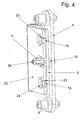
- the adjusting plate 10 is preferably guided displaceably in the direction of the axis of the adjusting spindle 11 on this. As in Fig. 4 to recognize, it has on at least one end face preferably a shoulder contour 38 for an operating tool such as an external polygonal key, the adjusting spindle 11 is accessible from the side of the front panel 1 through a hole 30 of the front panel 1.
- the adjusting plate 10 also preferably has an elliptical Shape or - particularly preferred - a circular shape and is penetrated by the adjusting spindle 11 off-center.
- the receiving plate 3 is provided on its side facing the adjusting plate 10 with two adjustment pins 15, which are arranged on both sides of a slot 18, which passes through the adjusting spindle 11 in the mounted state.
- the clamping plate has a corresponding slot 17.
- the adjusting plate 11 engages between these two adjusting pins 15th
- the adjusting plate 10 is arranged and designed relative to the adjustment pin 15 so that it acts with a rotation of the adjusting spindle 11 in the manner of an adjusting eccentric with its outer peripheral edge on each one of the adjustment pins 15, so that they are the unit of the receiving plate 3 and the clamping plate 2 shifts perpendicular to its plane of extension.
- Such a device for adjusting the vertical position of a door leaf is realized with only a few resources in a compact arrangement.
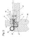
- the receiving plate 3 has on its opposite side of the adjusting disc 10 retaining pins 14 projecting therefrom in the direction of the clamping plate 4 and the one inserted between the clamping plate 2 and the receiving plate 3 frame part 22 of the door hinge 36 in its position to the receiving plate 3 after its horizontal orientation prefix, wherein the frame member 22 remains slidable in the vertical direction.
- the retaining pins 14 engage in receiving grooves 23 in the frame part 22 (see also Fig. 3 and 4 ).
- the clamping screw 8 passes through a bore 37 of the clamping plate 2 and is screwed into a threaded hole 16 in the receiving plate 3. With the clamping screw 8, which is accessible through a slot 39 of the front panel 1, the position of the frame part 22 between the receiving plate 3 and the clamping plate 2 can be prefixed without the clamping screws 7 must be tightened. In this way, the horizontal orientation is significantly simplified.
- clamping screws 7 are guided through the slots 12 in the clamping plate 2 and the slots 13 in the receiving plate 3 and screwed into threaded holes 20 in the adjustment plate 4, so that with dissolved clamping screws 7, the receiving plate 3 and the clamping plate 2 can be moved vertically together and are guided by the clamping screws 7.
- the clamping screws 7 are further guided by spacer plates 9, which are arranged between the receiving plate 3 and the adjusting plate 4 and which prevent deformation of the receiving plate 3 when tightening the clamping screws.
- the frame part has here in a conventional manner three grooves 22, which pass into three Verstellpper 24, this contour is known per se.
- the retaining pins 14 engage in at least one or two of the adjusting windows.
- the adjusting spindle 11 passes through the central adjustment window 24 of the inserted frame part 22 (FIG. Fig. 4 ). It is dimensioned so that the frame part 22 can change its position within the tape recording sufficiently in two directions.
- the adjusting spindle 11 has at the ends of a stepped projection 28 which engages in assembled pocket exactly in the receiving holes 29 and 30 of the bracket or the front panel and allows the rotation of the adjusting spindle.
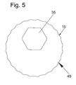
- the edge of the adjusting disk is wave-shaped and has depressions 31, such that the adjusting pins 15 engage in the depressions 31 in the manner of a grid, whereby an independent adjustment of the adjusting disk 10 is prevented in a simple manner ( Fig. 5 )
- the frame part 22 - here formed in a manner known per se - is pushed between the clamping plate 2 and the receiving plate 3. Then, the holding pins 14 are aligned and the horizontal position is pre-fixed with the screw 8. Now the vertical position can be adjusted with the adjusting device 34. Finally, the clamping screws 7 are fixed and the spindles 6 set. This type of assembly is simple and yet very precise feasible.
Landscapes
- Engineering & Computer Science (AREA)
- Mechanical Engineering (AREA)
- Hinges (AREA)
Abstract
Description
Die Erfindung betrifft eine Bandaufnahme nach dem Oberbegriff des Anspruchs 1.The invention relates to a tape recording according to the preamble of
Aus der
Bei diesem Bandaufnahmeelement können die Tür und insbesondere eine schwere Tür nach dem Lösen der Klemmschrauben nach unten rutschen. Um das Verrutschen zu verhindern, muß das Türgewicht bei gelösten Klemmschrauben gehalten werden und bei Justierung der Höhenlage des Türblatts muß das gesamte Türgewicht angehoben werden. In das Bandaufnahmeelement können übliche Bänder eingesetzt werden.In this tape receiving element, the door and in particular a heavy door after slackening the clamping screws can slide down. In order to prevent slippage, the door weight must be kept with the clamping screws loosened and when adjusting the height of the door leaf, the entire door weight must be raised. In the tape receiving element conventional tapes can be used.
Aus der
Die Verwendung von speziellen Rahmenteilen hat den Nachteil, dass die Verwendungsmöglichkeiten eingeschränkt werden und KombinationsMöglichkeiten mit anderen Bändern ausgeschlossen werden. Die direkte Klemmung des Bandlappens durch eine Schraube bei der Höhenverstellung kann bei schweren Türen problematisch werden und zum Verrutschen oder Verdrehen des Bandlappens führen. Die kurzen Gewindestifte mit Spitze müssen das gesamte Türgewicht bewegen, bzw. bei der Verstellung nach oben muß die gesamte Arbeit mit einem Gewindestift geleistet werden. Die Gewindestifte berühren die schrägen Bolzen nur auf einer kurzen Linie, was zu einer hohen Flächenpressung führt. Bei gelöster Klemmung muß der Bolzen mit dem Gewindestift die gesamte Belastung übertragen und bei der Verstellung von schweren Türen besteht die Gefahr der dauerhaften Verformung. Die Führung mit einem Langloch beim Einschieben oder Verstellen der Seitenlage kann das Verdrehen des Rahmenteils nicht sicher verhindern.The use of special frame parts has the disadvantage that the possibilities of use are limited and combinations with other bands are excluded. The direct clamping of the hinge strap by a screw in the height adjustment can be problematic for heavy doors and lead to slipping or twisting the hinge. The short threaded pins with tip must move the entire weight of the door, or in the adjustment to the top, the entire work must be done with a set screw. The grub screws touch the oblique bolts only on a short line, which leads to a high surface pressure. When the clamp is loosened, the bolt must transfer the entire load with the threaded pin and there is a risk of permanent deformation when adjusting heavy doors. The guide with a slot when inserting or adjusting the side position can not prevent the rotation of the frame part sure.
Der Erfindung liegt die Aufgabe zugrunde, die vorstehend beschriebenen Probleme zumindest teilweise zu beheben.The invention is based, at least partially, to remedy the problems described above the task.
Diese Aufgabe wird durch den Gegenstand des Anspruchs 1 gelöst.This object is solved by the subject matter of
Vorteilhafte Ausgestaltungen sind den Unteransprüchen zu entnehmen.Advantageous embodiments can be found in the dependent claims.
Erfindungsgemäß weist die Bandaufnahme eine Verstelleinrichtung mit einer Verstellscheibe auf, welche außermittig von einer Verstellwelle durchsetzt ist, wobei die Verstellscheibe auf wenigstens einen Verstellzapfen an der Klemmplatte oder ggf. der Aufnahmeplatte einwirkt.According to the invention, the tape holder has an adjusting device with an adjusting disk, which is passed off-center by an adjusting shaft, wherein the adjusting disk acts on at least one adjusting pin on the clamping plate or possibly the receiving plate.
Die Bandaufnahme verfügt damit über eine integrierte Hilfe zur Verstellung, insbesondere zur Höhenverstellung verfügt, die zudem in bevorzugter Weise derart ausgestaltet werden kann, dass sie auch übliche und vorhandene Bänder bzw. Rahmenteile aufnehmen kann, wobei sie das Rahmenteil unmittelbar klemmt und dabei das Verdrehen oder Verrutschen des Rahmenteils bei Einstellungen der Türlage sicher verhindert.The tape recording thus has an integrated aid for the adjustment, in particular for height adjustment, which can also be configured in a preferred manner so that they can also accommodate conventional and existing tapes or frame parts, wherein it clamps the frame member directly and thereby twisting or Slipping of the frame part safely prevented when setting the door position.
Derart kann das Türband bzw. dass daran angeordnete Türblatt auf einfache Weise in einer Dimension- insbesondere in vertikaler Richtung - verschoben werden.In this way, the door hinge or the door leaf arranged thereon can be displaced in a simple manner in one dimension, in particular in the vertical direction.
Ist eine Verstellung in weiteren Dimensionen gewünscht, kann diese Verstellbarkeit auch auf andere Weise realisiert werden, so durch Verstellspindeln oder einfach durch ein Verschieben in horizontaler Richtung. Es ist auch denkbar, in horizontaler Richtung eine zweite Verstelleinrichtung der aufgezeigten Art am Band auszubilden.If an adjustment in other dimensions desired, this adjustability can also be realized in other ways, so by adjusting spindles or simply by a displacement in the horizontal direction. It is also conceivable to form a second adjusting device of the type shown on the belt in the horizontal direction.
Vorzugsweise ist die Verstellscheibe kreisrund. Denkbar ist aber theoretisch auch eine elliptische Form.Preferably, the adjusting disc is circular. In theory, however, an elliptical shape is also conceivable.
Nachfolgend wird die Erfindung anhand eines Ausführungsbeispiels unter Bezug auf die Zeichnung näher beschrieben. Es zeigt:
-
Fig. 1 eine Sprengansicht einer erfindungsgemäßen Bandaufnahme; -
Fig. 2 eine Schnittansicht durch die zusammengesetzte Bandaufnahme ausFig.1 ; -
Fig. 3 einen Schnitt durch eine an einem Rahmen montierte Bandaufnahme mit eingesetztem Band; -
Fig. 4 eine perspektivische Ansicht von Bauelementen der Bandaufnahme ausFig.1 mit einem Türband; und -
Fig. 5 eine Skizze von Elementen einer weiteren erfindungsgemäßen Bandaufnahme.
-
Fig. 1 an explosive view of a tape recording according to the invention; -
Fig. 2 a sectional view through the composite tape recordingFig.1 ; -
Fig. 3 a section through a mounted on a frame tape recording with inserted tape; -
Fig. 4 a perspective view of components of the tape recordingFig.1 with a door hinge; and -
Fig. 5 a sketch of elements of another tape recording according to the invention.
Sofern nachfolgend Begriffe wie horizontal und vertikal verwendet werden, sind diese nicht einschränkend zu verstehen sondern diesen lediglich zur Veranschaulichung anhand des Beispiels von Türbändern mit vertikal ausgerichteter Drehachse.As used herein, terms such as horizontal and vertical are not meant to be limiting but merely illustrative thereof by way of example of door hinges having a vertically oriented axis of rotation.
Die Bandaufnahme weist eine Frontplatte 1 auf, an der ein Bügel 5 angebracht ist. Dieser Bügel 5 kann ein- oder mehrteilig ausgebildet sein. Er kann auch durch eine Platte mit Distanzstücken zur Frontplatte gebildet werden.The tape holder has a
Die Frontplatte 1 ist mit dem Bügel 5 verschraubbar, wobei zwischen diesen beiden Elementen 1, 5 im montierten Zustand ein Aufnahmeraum R für Funktionselemente der Bandaufnahmevorrichtung gebildet wird.The
Der Bügel 5 weist einen im montierten Zustand zur Frontplatte 1 beabstandeten Grundabschnitt 5a auf, der an seinen beiden Enden senkrecht zum Grundabschnitt verlaufende Schenkel 5b, 5c aufweist, an die relativ zum Grundabschnitt nach außen hin rechtwinklig Befestigungsabschnitte 5d, 5e angeformt sind, die im montierten Zustand wiederum auf den Endbereichen der Frontplatte aufliegen und Durchgangslöcher 31 für Schrauben aufweisen, die im montierten Zustand mit korrespondierenden Durchgangslöcher 32 in der Frontplatte 1 fluchten (Schrauben hier nicht dargestellt).The
Hier sind in den Aufnahmeraum R ausgehend von der Frontplatte 1 in Richtung des Bügels 5 nebeneinander drei im wesentlichen parallel zur Frontplatte ausgerichtete Platten eingesetzt: eine Klemmplatte 2, eine Aufnahmeplatte 3 und eine Verstellplatte 4.Here are in the receiving space R, starting from the
Die Schenkel 5b, 5c des Bügels sind derart gebogen ausgebildet, dass sie im Zusammenspiel eine Aufnahme für hier ebenfalls abgerundete Endbereiche 33 der Verstellplatte 4 ausbilden, die von der offenen Seite des Bügels 5 her in den Bügel 5 einsetzbar ist.The
Durch die Verstellplatte 4 sind zwei zueinander parallel ausgerichtete Verstellspindeln 6 geschraubt, die zwischen die Frontplatte 1 und den Bügel 5 eingesetzt werden. Hier sind die Verstellspindeln 6 jeweils in den voneinander abgewandten Endbereichen der Verstellplatte 4 angeordnet. Die Verstellspindeln 6 (siehe auch
Die Klemmplatte 2 ist ferner mit Klemmschrauben 7 an der Verstellplatte befestigt ist, welche ein Festklemmen eines Bandlappens (in
Die Aufnahmeplatte 3 ist gemeinsam mit der Klemmplatte 2 bei gelösten Klemmschrauben 7 als Einheit relativ zur Verstellplatte 4 mittels einer Verstelleinrichtung 34 vertikal verschiebbar.The
In Ergänzung der zwei Stellspindeln 6 ist hierzu wenigstens eine weitere Verstellspindel 11 zwischen der Frontplatte und dem Bügel angeordnet, die einen Teil der Verstelleinrichtung 34 bildet.In addition to the two adjusting
Diese Verstellspindel 11 durchsetzt eine Klemmplatte 2, die Aufnahmeplatte 3 und die Verstellplatte 4 und eine Öffnung 32 einer Verstellplatte 10 als weiteres Element der Verstelleinrichtung 34.This adjusting
Die Verstellspindel 11 ist formschlüssig mit der Verstellplatte 10 verbunden, was z.B. dadurch realisierbar ist, dass die Öffnung 32 die Kontur eines Innenmehrkants, beispielsweise eines Innensechskants, hat und die Verstellspindel 11 eine korrespondierende Kontur eines Außenmehrkant, insbesondere eines Außensechskants. Die Verstellscheibe 10 ist vorzugsweise in Richtung der Achse der Verstellspindel 11 auf dieser verschieblich geführt. Wie in
Die Aufnahmeplatte 3 ist auf ihrer der Verstellplatte 10 zugewandten Seite mit zwei Verstellzapfen 15 versehen, die beidseits eines Langloches 18 angeordnet sind, welche die Verstellspindel 11 im montierten Zustand durchsetzt. Die Klemmplatte weist ein korrespondierendes Langloch 17 auf.The
Die Verstellplatte 11 greift zwischen diese beiden Verstellzapfen 15.The adjusting
Die Verstellscheibe 10 ist dabei derart angeordnet und relativ zu den Verstellzapfen 15 ausgelegt, dass sie bei einem Drehen der Verstellspindel 11 nach Art eines Verstellexzenters mit ihrem Außenumfangsrand auf jeweils einen der Verstellzapfen 15 einwirkt, so dass sie die Einheit aus der Aufnahmeplatte 3 und der Klemmplatte 2 senkrecht zu ihrer Erstreckungsebene verschiebt.The adjusting
Wird die Verstellspindel 11 gedreht, die an der Verstellplatte 4 zwar verdrehbar ist, verschieben sich die Klemmplatte 2 und die Aufnahmeplatte 3 vertikal mit dem Türband.If the adjusting
Derart wird mit nur wenigen Mitteln in kompakter Anordnung eine Einrichtung zur Einstellung der Vertikalposition eines Türblattes realisiert.Such a device for adjusting the vertical position of a door leaf is realized with only a few resources in a compact arrangement.
Die Aufnahmeplatte 3 weist auf ihrer der Verstellscheibe 10 gegenüberliegenden Seite Haltezapfen 14 auf, die von dieser in Richtung der Klemmplatte 4 vorstehen und die ein zwischen der Klemmplatte 2 und der Aufnahmeplatte 3 eingeschobenes Rahmenteil 22 des Türbandes 36 in seiner Lage zur Aufnahmeplatte 3 nach seiner Horizontalausrichtung vorfixieren, wobei das Rahmenteil 22 in der Vertikalrichtung verschiebbar bleibt. Die Haltezapfen 14 greifen dabei in Aufnahmenuten 23 im Rahmenteil 22 ein (siehe auch
Die Klemmschraube 8 durchsetzt eine Bohrung 37 der Klemmplatte 2 und ist in ein Gewindeloch 16 in der Aufnahmeplatte 3 eingeschraubt. Mit der Klemmschraube 8, die durch ein Langloch 39 der Frontplatte 1 zugänglich ist, kann die Lage des Rahmenteils 22 zwischen der Aufnahmeplatte 3 und der Klemmplatte 2 vorfixiert werden, ohne dass die Klemmschrauben 7 angezogen sein müssen. Derart wird auch die Horizontalausrichtung deutlich vereinfacht.The clamping
Die Klemmschrauben 7 sind durch die Langlöcher 12 in der Klemmplatte 2 und die Langlöcher 13 in der Aufnahmeplatte 3 geführt und in Gewindelöcher 20 in der Verstellplatte 4 geschraubt, so dass bei gelösten Klemmschrauben 7 die Aufnahmeplatte 3 und die Klemmplatte 2 gemeinsam vertikal verschoben werden können und dabei von den Klemmschrauben 7 geführt werden.The clamping screws 7 are guided through the
Die Klemmschrauben 7 sind ferner durch Distanzplatten 9 geführt, welche zwischen der Aufnahmeplatte 3 und der Verstellplatte 4 angeordnet sind und welche beim Anziehen der Klemmschrauben ein Verformen der Aufnahmeplatte 3 verhindern.The clamping screws 7 are further guided by
Das Rahmenteil weist hier in an sich bekannter Weise drei Aufnahmenuten 22 auf, die in drei Verstellfenster 24 übergehen, wobei diese Kontur an sich bekannt ist. In wenigstens eines oder zwei der Verstellfenster greifen die Haltezapfen 14 ein.The frame part has here in a conventional manner three
Die Verstellspindel 11 durchsetzt dagegen das mittige Verstellfenster 24 des eingeschobenen Rahmenteils 22 (
Die Verstellspindel 11 weist an den Enden einen abgesetzten Ansatz 28 auf, der bei zusammenmontierter Tasche genau in die Aufnahmelöcher 29 und 30 des Bügels bzw. der Frontplatte greift und das Drehen der Verstellspindel ermöglicht.The adjusting
Es ist auch denkbar, dass der Rand der Verstellscheibe wellenförmig ausgebildet ist und Vertiefungen 31 aufweist, derart, dass die Verstellzapfen 15 rasterartig in die Vertiefungen 31 eingreifen, wodurch auf einfache Weise ein selbstständiges Verstellen der Verstellscheibe 10 verhindert wird (
Bei der Montage wird das - hier in an sich in bekannter Weise ausgebildete - Rahmenteil 22 zwischen die Klemmplatte 2 und die Aufnahmeplatte 3 geschoben. Sodann werden die Haltezapfen 14 ausgerichtet und die horizontale Lage wird mit der Schraube 8 vorfixiert. Jetzt kann die vertikale Lage mit der Verstelleinrichtung 34 eingestellt werden. Schließlich werden noch die Klemmschrauben 7 fixiert und die Spindeln 6 eingestellt. Diese Art der Montage ist einfach und dennoch besonders präzise durchführbar.During assembly, the frame part 22 - here formed in a manner known per se - is pushed between the clamping
- 11
- Frontplattefront panel
- 22
- Klemmplatteclamp
- 33
- Aufnahmeplattemounting plate
- 44
- Verstellplatteadjusting plate
- 55
-
Bügel; Abschnitte, Schenkel 5a - 5eHanger; Sections,
legs 5a - 5e - 66
- Spindelspindle
- 77
- Klemmschraube außenClamping screw outside
- 88th
- Klemmschraube innenClamping screw inside
- 99
- Distanzplattespacer plate
- 1010
- Verstellscheibeadjusting disc
- 1111
- Verstellspindel innenAdjusting spindle inside
- 1212
- LanglochLong hole
- 1313
- LanglochLong hole
- 1414
- Haltezapfenretaining pins
- 1515
- Verstellzapfenadjustment peg
- 1616
- Gewindelochthreaded hole
- 1717
- LanglochLong hole
- 1818
- LanglochLong hole
- 1919
- Gewindelochthreaded hole
- 2020
- Gewindelochthreaded hole
- 2121
- DurchgangslochThrough Hole
- Z22Z22
- Rahmenteilframe part
- 2323
- Aufnahmenutreceiving groove
- 2424
- Verstellfenster RTAdjusting window RT
- 2525
- Flügelteilwing part
- 2626
- Türblattdoor leaf
- 2727
- Türzargedoor frame
- 2828
- Ansatzapproach
- 2929
- Aufnahmeloch BügelRecording hole hanger
- 3030
- Aufnahmeloch FrontplatteRecording hole front panel
- 31, 3231, 32
- DurchgangslöcherThrough holes
- 3333
- Endbereicheend regions
- 3434
- Verstelleinrichtungadjustment
- 3636
- Türbandhinge
- 3737
- Bohrungdrilling
- 3838
- Ansatzkonturapproach contour
- 3939
- LanglochLong hole
Claims (14)
Priority Applications (1)
| Application Number | Priority Date | Filing Date | Title |
|---|---|---|---|
| PL07123119T PL1936082T3 (en) | 2006-12-19 | 2007-12-13 | Hinge retainer with integrated height adjustment for door frames |
Applications Claiming Priority (1)
| Application Number | Priority Date | Filing Date | Title |
|---|---|---|---|
| DE102006060463A DE102006060463B3 (en) | 2006-12-19 | 2006-12-19 | Strip holder for inserting into door casements comprises an adjusting unit with an adjusting plate penetrated by an adjusting spindle |
Publications (3)
| Publication Number | Publication Date |
|---|---|
| EP1936082A2 true EP1936082A2 (en) | 2008-06-25 |
| EP1936082A3 EP1936082A3 (en) | 2012-07-04 |
| EP1936082B1 EP1936082B1 (en) | 2015-03-04 |
Family
ID=39134755
Family Applications (1)
| Application Number | Title | Priority Date | Filing Date |
|---|---|---|---|
| EP07123119.5A Active EP1936082B1 (en) | 2006-12-19 | 2007-12-13 | Hinge retainer with integrated height adjustment for door frames |
Country Status (3)
| Country | Link |
|---|---|
| EP (1) | EP1936082B1 (en) |
| DE (1) | DE102006060463B3 (en) |
| PL (1) | PL1936082T3 (en) |
Cited By (1)
| Publication number | Priority date | Publication date | Assignee | Title |
|---|---|---|---|---|
| CN113719207A (en) * | 2021-08-10 | 2021-11-30 | 浙江王力安防产品有限公司 | Hinge adjusting structure |
Families Citing this family (4)
| Publication number | Priority date | Publication date | Assignee | Title |
|---|---|---|---|---|
| DE102008016367B4 (en) * | 2008-03-29 | 2016-01-07 | Bartels Systembeschläge GmbH | Door hinge for concealed installation for rotatably connecting a door leaf to a door frame with three-dimensional adjustment and internal adjustment |
| DE102008036151A1 (en) | 2008-08-01 | 2010-02-04 | Glutz Deutschland Gmbh | Hinge strap with a substructure for attachment to a door leaf |
| DE102010012144B3 (en) * | 2010-03-20 | 2011-09-15 | Simonswerk, Gesellschaft mit beschränkter Haftung | Door hinge for rebated building doors made of wood |
| EP3401479B1 (en) * | 2017-05-10 | 2023-09-06 | Grass GmbH | Upper flap fitting for furniture |
Citations (2)
| Publication number | Priority date | Publication date | Assignee | Title |
|---|---|---|---|---|
| DE20210049U1 (en) | 2002-06-29 | 2003-02-20 | Bartels Systembeschlaege Gmbh | Hinge holder element for door cases and casings comprises adjusting spindles inserted in receiving bores between the rear plate and the front plate |
| DE102004042924B3 (en) | 2004-09-02 | 2005-12-22 | Simonswerk, Gmbh | Door hinge and hinge-recess arrangement, has hinge flap which is thicker than spacing between connection surface and carrier plate, and with tapered insertion edge that is thinner than spacing |
Family Cites Families (4)
| Publication number | Priority date | Publication date | Assignee | Title |
|---|---|---|---|---|
| DE19951155C2 (en) * | 1999-10-23 | 2003-02-06 | Simonswerk,Gmbh | hinge device |
| DE10051966A1 (en) * | 2000-10-20 | 2002-05-16 | Winkhaus Fa August | Display device for a tilt or turn-tilt wing hinged to a frame |
| AT6962U1 (en) * | 2003-02-21 | 2004-06-25 | Blum Gmbh Julius | HINGE |
| NO20061548L (en) * | 2006-04-05 | 2007-10-08 | Frip As | Hinge height adjustment device |
-
2006
- 2006-12-19 DE DE102006060463A patent/DE102006060463B3/en active Active
-
2007
- 2007-12-13 EP EP07123119.5A patent/EP1936082B1/en active Active
- 2007-12-13 PL PL07123119T patent/PL1936082T3/en unknown
Patent Citations (2)
| Publication number | Priority date | Publication date | Assignee | Title |
|---|---|---|---|---|
| DE20210049U1 (en) | 2002-06-29 | 2003-02-20 | Bartels Systembeschlaege Gmbh | Hinge holder element for door cases and casings comprises adjusting spindles inserted in receiving bores between the rear plate and the front plate |
| DE102004042924B3 (en) | 2004-09-02 | 2005-12-22 | Simonswerk, Gmbh | Door hinge and hinge-recess arrangement, has hinge flap which is thicker than spacing between connection surface and carrier plate, and with tapered insertion edge that is thinner than spacing |
Cited By (1)
| Publication number | Priority date | Publication date | Assignee | Title |
|---|---|---|---|---|
| CN113719207A (en) * | 2021-08-10 | 2021-11-30 | 浙江王力安防产品有限公司 | Hinge adjusting structure |
Also Published As
| Publication number | Publication date |
|---|---|
| DE102006060463B3 (en) | 2008-04-03 |
| EP1936082B1 (en) | 2015-03-04 |
| PL1936082T3 (en) | 2015-07-31 |
| EP1936082A3 (en) | 2012-07-04 |
Similar Documents
| Publication | Publication Date | Title |
|---|---|---|
| EP2715021B1 (en) | Hinge | |
| DE202015103874U1 (en) | Device for connecting two furniture parts | |
| EP1936082B1 (en) | Hinge retainer with integrated height adjustment for door frames | |
| EP2085553B1 (en) | Fitting for a corner support | |
| EP2365167B1 (en) | Hinge, especially for building closing doors | |
| EP1893836B1 (en) | Furniture hinge | |
| EP0285229A2 (en) | Adjustable hinge, especially for doors | |
| EP2366857B1 (en) | Mounting arrangement for a sliding door | |
| EP1094183B1 (en) | Hinge device | |
| EP2365166B1 (en) | Hinge, especially for building closing doors | |
| DE102006012157B4 (en) | Three-dimensionally adjustable belt pocket system with adjustment aid for height adjustment and associated frame part | |
| EP2206861A2 (en) | Door hinge assembly | |
| DE19921796B4 (en) | Belt pocket for a hinge construction | |
| DE202010013187U1 (en) | Arrangement of a drive unit of an opening or locking device | |
| EP2149664B1 (en) | Supporting structure for a hinge and hinge with such a supporting structure for attachment to a door leaf | |
| EP1394347B1 (en) | Device for guiding sliding partitions and elastic guiding element | |
| EP1632630B1 (en) | Slot of door fittings for adjustably mounting the hinge | |
| AT500599B1 (en) | MULTI-DIMENSIONAL ADJUSTABLE DOOR BAND | |
| EP2172610B1 (en) | Hinge mounting part | |
| EP2304148B1 (en) | Hinge system | |
| DE102006012051B4 (en) | Tape holder with integrated height adjustment for door frames for mounting frame parts for three-dimensional adjustment | |
| EP3219891A1 (en) | Three-dimensionally adjustable hinge system | |
| EP2740872B1 (en) | Corner bearing for concealed assembly | |
| EP2754807A1 (en) | Concealed door hinge | |
| EP1106763B1 (en) | Hinge for doors, windows or like that |
Legal Events
| Date | Code | Title | Description |
|---|---|---|---|
| PUAI | Public reference made under article 153(3) epc to a published international application that has entered the european phase |
Free format text: ORIGINAL CODE: 0009012 |
|
| AK | Designated contracting states |
Kind code of ref document: A2 Designated state(s): AT BE BG CH CY CZ DE DK EE ES FI FR GB GR HU IE IS IT LI LT LU LV MC MT NL PL PT RO SE SI SK TR |
|
| AX | Request for extension of the european patent |
Extension state: AL BA HR MK RS |
|
| PUAL | Search report despatched |
Free format text: ORIGINAL CODE: 0009013 |
|
| AK | Designated contracting states |
Kind code of ref document: A3 Designated state(s): AT BE BG CH CY CZ DE DK EE ES FI FR GB GR HU IE IS IT LI LT LU LV MC MT NL PL PT RO SE SI SK TR |
|
| AX | Request for extension of the european patent |
Extension state: AL BA HR MK RS |
|
| RIC1 | Information provided on ipc code assigned before grant |
Ipc: E05D 7/04 20060101AFI20120530BHEP |
|
| 17P | Request for examination filed |
Effective date: 20121128 |
|
| AKX | Designation fees paid |
Designated state(s): AT BE BG CH CY CZ DE DK EE ES FI FR GB GR HU IE IS IT LI LT LU LV MC MT NL PL PT RO SE SI SK TR |
|
| 17Q | First examination report despatched |
Effective date: 20140312 |
|
| GRAP | Despatch of communication of intention to grant a patent |
Free format text: ORIGINAL CODE: EPIDOSNIGR1 |
|
| INTG | Intention to grant announced |
Effective date: 20141015 |
|
| GRAS | Grant fee paid |
Free format text: ORIGINAL CODE: EPIDOSNIGR3 |
|
| GRAA | (expected) grant |
Free format text: ORIGINAL CODE: 0009210 |
|
| AK | Designated contracting states |
Kind code of ref document: B1 Designated state(s): AT BE BG CH CY CZ DE DK EE ES FI FR GB GR HU IE IS IT LI LT LU LV MC MT NL PL PT RO SE SI SK TR |
|
| REG | Reference to a national code |
Ref country code: GB Ref legal event code: FG4D Free format text: NOT ENGLISH |
|
| REG | Reference to a national code |
Ref country code: CH Ref legal event code: NV Representative=s name: ISLER AND PEDRAZZINI AG, CH Ref country code: CH Ref legal event code: EP |
|
| REG | Reference to a national code |
Ref country code: IE Ref legal event code: FG4D Free format text: LANGUAGE OF EP DOCUMENT: GERMAN |
|
| REG | Reference to a national code |
Ref country code: DE Ref legal event code: R096 Ref document number: 502007013765 Country of ref document: DE Effective date: 20150409 |
|
| REG | Reference to a national code |
Ref country code: AT Ref legal event code: REF Ref document number: 714071 Country of ref document: AT Kind code of ref document: T Effective date: 20150415 |
|
| REG | Reference to a national code |
Ref country code: NL Ref legal event code: T3 |
|
| PG25 | Lapsed in a contracting state [announced via postgrant information from national office to epo] |
Ref country code: LT Free format text: LAPSE BECAUSE OF FAILURE TO SUBMIT A TRANSLATION OF THE DESCRIPTION OR TO PAY THE FEE WITHIN THE PRESCRIBED TIME-LIMIT Effective date: 20150304 Ref country code: SE Free format text: LAPSE BECAUSE OF FAILURE TO SUBMIT A TRANSLATION OF THE DESCRIPTION OR TO PAY THE FEE WITHIN THE PRESCRIBED TIME-LIMIT Effective date: 20150304 Ref country code: FI Free format text: LAPSE BECAUSE OF FAILURE TO SUBMIT A TRANSLATION OF THE DESCRIPTION OR TO PAY THE FEE WITHIN THE PRESCRIBED TIME-LIMIT Effective date: 20150304 Ref country code: ES Free format text: LAPSE BECAUSE OF FAILURE TO SUBMIT A TRANSLATION OF THE DESCRIPTION OR TO PAY THE FEE WITHIN THE PRESCRIBED TIME-LIMIT Effective date: 20150304 |
|
| REG | Reference to a national code |
Ref country code: PL Ref legal event code: T3 |
|
| REG | Reference to a national code |
Ref country code: LT Ref legal event code: MG4D |
|
| PG25 | Lapsed in a contracting state [announced via postgrant information from national office to epo] |
Ref country code: LV Free format text: LAPSE BECAUSE OF FAILURE TO SUBMIT A TRANSLATION OF THE DESCRIPTION OR TO PAY THE FEE WITHIN THE PRESCRIBED TIME-LIMIT Effective date: 20150304 |
|
| PG25 | Lapsed in a contracting state [announced via postgrant information from national office to epo] |
Ref country code: SK Free format text: LAPSE BECAUSE OF FAILURE TO SUBMIT A TRANSLATION OF THE DESCRIPTION OR TO PAY THE FEE WITHIN THE PRESCRIBED TIME-LIMIT Effective date: 20150304 Ref country code: EE Free format text: LAPSE BECAUSE OF FAILURE TO SUBMIT A TRANSLATION OF THE DESCRIPTION OR TO PAY THE FEE WITHIN THE PRESCRIBED TIME-LIMIT Effective date: 20150304 Ref country code: PT Free format text: LAPSE BECAUSE OF FAILURE TO SUBMIT A TRANSLATION OF THE DESCRIPTION OR TO PAY THE FEE WITHIN THE PRESCRIBED TIME-LIMIT Effective date: 20150706 Ref country code: RO Free format text: LAPSE BECAUSE OF FAILURE TO SUBMIT A TRANSLATION OF THE DESCRIPTION OR TO PAY THE FEE WITHIN THE PRESCRIBED TIME-LIMIT Effective date: 20150304 |
|
| PG25 | Lapsed in a contracting state [announced via postgrant information from national office to epo] |
Ref country code: IS Free format text: LAPSE BECAUSE OF FAILURE TO SUBMIT A TRANSLATION OF THE DESCRIPTION OR TO PAY THE FEE WITHIN THE PRESCRIBED TIME-LIMIT Effective date: 20150704 |
|
| REG | Reference to a national code |
Ref country code: DE Ref legal event code: R097 Ref document number: 502007013765 Country of ref document: DE |
|
| PLBE | No opposition filed within time limit |
Free format text: ORIGINAL CODE: 0009261 |
|
| STAA | Information on the status of an ep patent application or granted ep patent |
Free format text: STATUS: NO OPPOSITION FILED WITHIN TIME LIMIT |
|
| PG25 | Lapsed in a contracting state [announced via postgrant information from national office to epo] |
Ref country code: DK Free format text: LAPSE BECAUSE OF FAILURE TO SUBMIT A TRANSLATION OF THE DESCRIPTION OR TO PAY THE FEE WITHIN THE PRESCRIBED TIME-LIMIT Effective date: 20150304 |
|
| 26N | No opposition filed |
Effective date: 20151207 |
|
| PG25 | Lapsed in a contracting state [announced via postgrant information from national office to epo] |
Ref country code: SI Free format text: LAPSE BECAUSE OF FAILURE TO SUBMIT A TRANSLATION OF THE DESCRIPTION OR TO PAY THE FEE WITHIN THE PRESCRIBED TIME-LIMIT Effective date: 20150304 |
|
| PG25 | Lapsed in a contracting state [announced via postgrant information from national office to epo] |
Ref country code: BE Free format text: LAPSE BECAUSE OF NON-PAYMENT OF DUE FEES Effective date: 20151231 |
|
| PG25 | Lapsed in a contracting state [announced via postgrant information from national office to epo] |
Ref country code: MC Free format text: LAPSE BECAUSE OF FAILURE TO SUBMIT A TRANSLATION OF THE DESCRIPTION OR TO PAY THE FEE WITHIN THE PRESCRIBED TIME-LIMIT Effective date: 20150304 Ref country code: LU Free format text: LAPSE BECAUSE OF FAILURE TO SUBMIT A TRANSLATION OF THE DESCRIPTION OR TO PAY THE FEE WITHIN THE PRESCRIBED TIME-LIMIT Effective date: 20151213 |
|
| GBPC | Gb: european patent ceased through non-payment of renewal fee |
Effective date: 20151213 |
|
| REG | Reference to a national code |
Ref country code: IE Ref legal event code: MM4A |
|
| REG | Reference to a national code |
Ref country code: FR Ref legal event code: ST Effective date: 20160831 |
|
| PG25 | Lapsed in a contracting state [announced via postgrant information from national office to epo] |
Ref country code: GB Free format text: LAPSE BECAUSE OF NON-PAYMENT OF DUE FEES Effective date: 20151213 Ref country code: IE Free format text: LAPSE BECAUSE OF NON-PAYMENT OF DUE FEES Effective date: 20151213 |
|
| PG25 | Lapsed in a contracting state [announced via postgrant information from national office to epo] |
Ref country code: FR Free format text: LAPSE BECAUSE OF NON-PAYMENT OF DUE FEES Effective date: 20151231 |
|
| PG25 | Lapsed in a contracting state [announced via postgrant information from national office to epo] |
Ref country code: HU Free format text: LAPSE BECAUSE OF FAILURE TO SUBMIT A TRANSLATION OF THE DESCRIPTION OR TO PAY THE FEE WITHIN THE PRESCRIBED TIME-LIMIT; INVALID AB INITIO Effective date: 20071213 Ref country code: BG Free format text: LAPSE BECAUSE OF FAILURE TO SUBMIT A TRANSLATION OF THE DESCRIPTION OR TO PAY THE FEE WITHIN THE PRESCRIBED TIME-LIMIT Effective date: 20150304 |
|
| PG25 | Lapsed in a contracting state [announced via postgrant information from national office to epo] |
Ref country code: CY Free format text: LAPSE BECAUSE OF FAILURE TO SUBMIT A TRANSLATION OF THE DESCRIPTION OR TO PAY THE FEE WITHIN THE PRESCRIBED TIME-LIMIT Effective date: 20150304 Ref country code: GR Free format text: LAPSE BECAUSE OF FAILURE TO SUBMIT A TRANSLATION OF THE DESCRIPTION OR TO PAY THE FEE WITHIN THE PRESCRIBED TIME-LIMIT Effective date: 20150304 |
|
| PG25 | Lapsed in a contracting state [announced via postgrant information from national office to epo] |
Ref country code: MT Free format text: LAPSE BECAUSE OF FAILURE TO SUBMIT A TRANSLATION OF THE DESCRIPTION OR TO PAY THE FEE WITHIN THE PRESCRIBED TIME-LIMIT Effective date: 20150304 Ref country code: TR Free format text: LAPSE BECAUSE OF FAILURE TO SUBMIT A TRANSLATION OF THE DESCRIPTION OR TO PAY THE FEE WITHIN THE PRESCRIBED TIME-LIMIT Effective date: 20150304 |
|
| PGFP | Annual fee paid to national office [announced via postgrant information from national office to epo] |
Ref country code: NL Payment date: 20221118 Year of fee payment: 16 |
|
| PGFP | Annual fee paid to national office [announced via postgrant information from national office to epo] |
Ref country code: CH Payment date: 20230101 Year of fee payment: 16 |
|
| PGFP | Annual fee paid to national office [announced via postgrant information from national office to epo] |
Ref country code: IT Payment date: 20221230 Year of fee payment: 16 |
|
| PGFP | Annual fee paid to national office [announced via postgrant information from national office to epo] |
Ref country code: CZ Payment date: 20231130 Year of fee payment: 17 Ref country code: AT Payment date: 20231204 Year of fee payment: 17 |
|
| PGFP | Annual fee paid to national office [announced via postgrant information from national office to epo] |
Ref country code: PL Payment date: 20231110 Year of fee payment: 17 |
|
| PGFP | Annual fee paid to national office [announced via postgrant information from national office to epo] |
Ref country code: DE Payment date: 20240122 Year of fee payment: 17 Ref country code: CH Payment date: 20240102 Year of fee payment: 17 |