EP1935731A2 - Gabelstapler mit einer Führung zur seitlichen Batterieentnahme - Google Patents
Gabelstapler mit einer Führung zur seitlichen Batterieentnahme Download PDFInfo
- Publication number
- EP1935731A2 EP1935731A2 EP07023264A EP07023264A EP1935731A2 EP 1935731 A2 EP1935731 A2 EP 1935731A2 EP 07023264 A EP07023264 A EP 07023264A EP 07023264 A EP07023264 A EP 07023264A EP 1935731 A2 EP1935731 A2 EP 1935731A2
- Authority
- EP
- European Patent Office
- Prior art keywords
- wedge
- holding device
- battery
- push rod
- truck according
- Prior art date
- Legal status (The legal status is an assumption and is not a legal conclusion. Google has not performed a legal analysis and makes no representation as to the accuracy of the status listed.)
- Granted
Links
Images

Classifications
-
- B—PERFORMING OPERATIONS; TRANSPORTING
- B60—VEHICLES IN GENERAL
- B60K—ARRANGEMENT OR MOUNTING OF PROPULSION UNITS OR OF TRANSMISSIONS IN VEHICLES; ARRANGEMENT OR MOUNTING OF PLURAL DIVERSE PRIME-MOVERS IN VEHICLES; AUXILIARY DRIVES FOR VEHICLES; INSTRUMENTATION OR DASHBOARDS FOR VEHICLES; ARRANGEMENTS IN CONNECTION WITH COOLING, AIR INTAKE, GAS EXHAUST OR FUEL SUPPLY OF PROPULSION UNITS IN VEHICLES
- B60K1/00—Arrangement or mounting of electrical propulsion units
- B60K1/04—Arrangement or mounting of electrical propulsion units of the electric storage means for propulsion
-
- B—PERFORMING OPERATIONS; TRANSPORTING
- B60—VEHICLES IN GENERAL
- B60L—PROPULSION OF ELECTRICALLY-PROPELLED VEHICLES; SUPPLYING ELECTRIC POWER FOR AUXILIARY EQUIPMENT OF ELECTRICALLY-PROPELLED VEHICLES; ELECTRODYNAMIC BRAKE SYSTEMS FOR VEHICLES IN GENERAL; MAGNETIC SUSPENSION OR LEVITATION FOR VEHICLES; MONITORING OPERATING VARIABLES OF ELECTRICALLY-PROPELLED VEHICLES; ELECTRIC SAFETY DEVICES FOR ELECTRICALLY-PROPELLED VEHICLES
- B60L53/00—Methods of charging batteries, specially adapted for electric vehicles; Charging stations or on-board charging equipment therefor; Exchange of energy storage elements in electric vehicles
- B60L53/80—Exchanging energy storage elements, e.g. removable batteries
-
- B—PERFORMING OPERATIONS; TRANSPORTING
- B66—HOISTING; LIFTING; HAULING
- B66F—HOISTING, LIFTING, HAULING OR PUSHING, NOT OTHERWISE PROVIDED FOR, e.g. DEVICES WHICH APPLY A LIFTING OR PUSHING FORCE DIRECTLY TO THE SURFACE OF A LOAD
- B66F9/00—Devices for lifting or lowering bulky or heavy goods for loading or unloading purposes
- B66F9/06—Devices for lifting or lowering bulky or heavy goods for loading or unloading purposes movable, with their loads, on wheels or the like, e.g. fork-lift trucks
- B66F9/075—Constructional features or details
- B66F9/07513—Details concerning the chassis
- B66F9/0754—Battery removal arrangements
-
- B—PERFORMING OPERATIONS; TRANSPORTING
- B60—VEHICLES IN GENERAL
- B60K—ARRANGEMENT OR MOUNTING OF PROPULSION UNITS OR OF TRANSMISSIONS IN VEHICLES; ARRANGEMENT OR MOUNTING OF PLURAL DIVERSE PRIME-MOVERS IN VEHICLES; AUXILIARY DRIVES FOR VEHICLES; INSTRUMENTATION OR DASHBOARDS FOR VEHICLES; ARRANGEMENTS IN CONNECTION WITH COOLING, AIR INTAKE, GAS EXHAUST OR FUEL SUPPLY OF PROPULSION UNITS IN VEHICLES
- B60K1/00—Arrangement or mounting of electrical propulsion units
- B60K1/04—Arrangement or mounting of electrical propulsion units of the electric storage means for propulsion
- B60K2001/0455—Removal or replacement of the energy storages
- B60K2001/0461—Removal or replacement of the energy storages from the side
-
- B—PERFORMING OPERATIONS; TRANSPORTING
- B60—VEHICLES IN GENERAL
- B60K—ARRANGEMENT OR MOUNTING OF PROPULSION UNITS OR OF TRANSMISSIONS IN VEHICLES; ARRANGEMENT OR MOUNTING OF PLURAL DIVERSE PRIME-MOVERS IN VEHICLES; AUXILIARY DRIVES FOR VEHICLES; INSTRUMENTATION OR DASHBOARDS FOR VEHICLES; ARRANGEMENTS IN CONNECTION WITH COOLING, AIR INTAKE, GAS EXHAUST OR FUEL SUPPLY OF PROPULSION UNITS IN VEHICLES
- B60K1/00—Arrangement or mounting of electrical propulsion units
- B60K1/04—Arrangement or mounting of electrical propulsion units of the electric storage means for propulsion
- B60K2001/0455—Removal or replacement of the energy storages
- B60K2001/0472—Removal or replacement of the energy storages from below
-
- B—PERFORMING OPERATIONS; TRANSPORTING
- B60—VEHICLES IN GENERAL
- B60L—PROPULSION OF ELECTRICALLY-PROPELLED VEHICLES; SUPPLYING ELECTRIC POWER FOR AUXILIARY EQUIPMENT OF ELECTRICALLY-PROPELLED VEHICLES; ELECTRODYNAMIC BRAKE SYSTEMS FOR VEHICLES IN GENERAL; MAGNETIC SUSPENSION OR LEVITATION FOR VEHICLES; MONITORING OPERATING VARIABLES OF ELECTRICALLY-PROPELLED VEHICLES; ELECTRIC SAFETY DEVICES FOR ELECTRICALLY-PROPELLED VEHICLES
- B60L2200/00—Type of vehicles
- B60L2200/40—Working vehicles
- B60L2200/42—Fork lift trucks
-
- B—PERFORMING OPERATIONS; TRANSPORTING
- B60—VEHICLES IN GENERAL
- B60Y—INDEXING SCHEME RELATING TO ASPECTS CROSS-CUTTING VEHICLE TECHNOLOGY
- B60Y2200/00—Type of vehicle
- B60Y2200/10—Road Vehicles
- B60Y2200/15—Fork lift trucks, Industrial trucks
-
- Y—GENERAL TAGGING OF NEW TECHNOLOGICAL DEVELOPMENTS; GENERAL TAGGING OF CROSS-SECTIONAL TECHNOLOGIES SPANNING OVER SEVERAL SECTIONS OF THE IPC; TECHNICAL SUBJECTS COVERED BY FORMER USPC CROSS-REFERENCE ART COLLECTIONS [XRACs] AND DIGESTS
- Y02—TECHNOLOGIES OR APPLICATIONS FOR MITIGATION OR ADAPTATION AGAINST CLIMATE CHANGE
- Y02P—CLIMATE CHANGE MITIGATION TECHNOLOGIES IN THE PRODUCTION OR PROCESSING OF GOODS
- Y02P90/00—Enabling technologies with a potential contribution to greenhouse gas [GHG] emissions mitigation
- Y02P90/60—Electric or hybrid propulsion means for production processes
-
- Y—GENERAL TAGGING OF NEW TECHNOLOGICAL DEVELOPMENTS; GENERAL TAGGING OF CROSS-SECTIONAL TECHNOLOGIES SPANNING OVER SEVERAL SECTIONS OF THE IPC; TECHNICAL SUBJECTS COVERED BY FORMER USPC CROSS-REFERENCE ART COLLECTIONS [XRACs] AND DIGESTS
- Y02—TECHNOLOGIES OR APPLICATIONS FOR MITIGATION OR ADAPTATION AGAINST CLIMATE CHANGE
- Y02T—CLIMATE CHANGE MITIGATION TECHNOLOGIES RELATED TO TRANSPORTATION
- Y02T10/00—Road transport of goods or passengers
- Y02T10/60—Other road transportation technologies with climate change mitigation effect
- Y02T10/70—Energy storage systems for electromobility, e.g. batteries
-
- Y—GENERAL TAGGING OF NEW TECHNOLOGICAL DEVELOPMENTS; GENERAL TAGGING OF CROSS-SECTIONAL TECHNOLOGIES SPANNING OVER SEVERAL SECTIONS OF THE IPC; TECHNICAL SUBJECTS COVERED BY FORMER USPC CROSS-REFERENCE ART COLLECTIONS [XRACs] AND DIGESTS
- Y02—TECHNOLOGIES OR APPLICATIONS FOR MITIGATION OR ADAPTATION AGAINST CLIMATE CHANGE
- Y02T—CLIMATE CHANGE MITIGATION TECHNOLOGIES RELATED TO TRANSPORTATION
- Y02T10/00—Road transport of goods or passengers
- Y02T10/60—Other road transportation technologies with climate change mitigation effect
- Y02T10/7072—Electromobility specific charging systems or methods for batteries, ultracapacitors, supercapacitors or double-layer capacitors
Definitions
- the invention relates to an industrial truck, in particular forklift truck, with a vehicle frame, which has a lateral removal opening for a battery block, wherein for the battery block a holding device and at least one swing-out support device for the holding device is provided, wherein the holding device by means of a guide between an operating position, in the holder is completely within the vehicle frame, and a battery changing position, in which the holding device is completely outside the vehicle frame, is movable.
- the removal device must be made very stable in order to transfer the weight of the battery to the truck can. Therefore it is, for example from the DE 10 2005 025 647 known to provide a arranged on the guide device, pivotable on a road surface support device. If the support device lowered, the holding device is partially supported on this, so that the truck can not tip over and forces acting on the attachment of the fixture on the truck can be reduced.
- the pivoting or extension of the support device can be made for example by means of a drive device.
- electrical or hydraulic drive devices are expensive, require power, are prone to error and difficult to maintain.
- the invention is therefore based on the object to provide an industrial truck according to the preamble of claim 1, which is simple in construction and in which a support of the removal device and the battery pack arranged thereon is made possible by simple means.
- the support device by means of spring force and / or weight from a raised to a lowered position is movable and at least one device for automatic locking of the support device is provided in the lowered position.
- the support device is lowered by spring force and / or weight, no external power supply is necessary.
- a spring drive is simple, maintenance-free, easy to protect against overload and inexpensive to produce. In the interaction of weight and spring force is with very high security ensures that the support is really lowered.
- An automatic locking in the lowered position is particularly advantageous because so the support member against unintentional pivoting, in particular retraction, is secured without the operator must intervene by inserting or loosening the lock. In this case, embodiments are to be preferred in which the spring drive does not have to apply the forces required for locking or only to a small extent.
- the device for locking the support device in the lowered position is designed as a wedge device.
- Wedge devices allow easy fixation of moving parts, in which the strength of the fixation increases with increasing distance. A solution of the fixation is possible with little effort and very short adjustment.
- the wedge device is designed so that the forces to achieve the wedge effect by the weight of the battery and / or the holding device can be applied. This can be dispensed with expensive devices that apply the forces for locking the support device. With increasing weight, for example when using a heavier battery, the locking effect is increased. The power to release the lock is therefore also dependent on the weight of the battery, so that no unnecessary large forces must be applied to light batteries.
- the swing-out supporting device prefferably has at least one first articulated arm which is pivotably arranged on the holding device and has a roller rotatably mounted on the pivotably arranged arm.
- a roller allows easy lateral movement of the holding device.
- the swing-out support device has at least one second articulated arm between the roller and a first push rod movable parallel to the extension direction. By moving the push rod, the roller can be raised or lowered,
- the wedge tip is aligned in the direction of movement of the push rod away from the roller, a movement of the push rod in this direction can be blocked and thus the roller in position locked.
- a second, parallel to Ausschubraum movable push rod which has a second wedge-shaped element which can be brought into engagement with the first wedge-shaped element. By moving the push rods in opposite directions, the wedge device and thus the support member can be locked.
- the wedge-shaped elements are mounted in a guide with a preferably rectangular cross-section.
- a guide is a particularly simple way to both guide the wedge-shaped elements and bring about the wedge effect by a force approximately perpendicular to the direction of movement of the push rods.
- At least one of the push rods, preferably the second push rod, by means of spring force against the Ausschubides the battery from a fully inserted position (operating position) in a fully extended position (battery replacement position) is movable.
- the push rods preferably the second push rod, by means of spring force against the Ausschubides the battery from a fully inserted position (operating position) in a fully extended position (battery replacement position) is movable.
- At least one of the wedge-shaped elements on the side facing away from the wedge surface has a wave-shaped profile and the guide of the wedge-shaped elements on the side surface facing surface has an approximately similar wave-shaped profile.
- the first push rod preferably on the wedge tip of the first wedge-shaped element, a stop on which a part of the second push rod, preferably facing away from the wedge tip portion of the second wedge-shaped element, directed by a counter to the wedge action Relative movement of the push rods can be brought into contact. Characterized a entrainment of the first push rod by the second push rod is possible in a movement that leads to the release of the wedge effect, for example, leads to the pivoting of the support device.
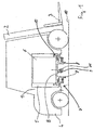
- FIG. 1 shows a forklift invention in side view.
- the load-bearing element of the forklift is a vehicle frame 1.
- a mast 2 is mounted with a load-receiving means 3 movable up and down.
- a tail weight 4 is movable up and down.
- a laterally open battery compartment 5 In a free space of the vehicle frame is a laterally open battery compartment 5, in which a battery block 6 is arranged.
- the battery block 6 rests on a holding device 7, which can be moved out of the battery compartment 5 in the lateral direction by means of a telescopic guide 8.
- a swing-out support device 9 is attached on the holding device 7. As long as the holding device 7 is in the operating position within the vehicle frame 1, the support device 9 is pivoted in and is located within the vehicle contour. As soon as the support device 9 is moved out of the vehicle, it is automatically swung out and supports the weight of the battery block 6 directly on the roadway 10. At the lower end of the support device 9 is a roller 11, which rolls on the roadway 10 during the extension movement.
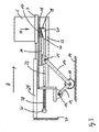
- FIG. 2 is schematically the guide 8 of the retainer 7 shown in side view.
- the roller 11 On the holding device 7 with the battery 6, the roller 11 is attached via a joint 12 and a first articulated arm 13.
- a second articulated arm 14 and a hinge 15 connect the roller 11 with a first push rod 16, which is movably mounted in relation to the holding device 7 parallel to the extension direction A of the battery 6.
- a first wedge member 17 At the end of the first push rod 16, a first wedge member 17 is arranged, the tip 18 points away in the direction of movement A of the push rod 16 away from the roller 11.
- a stop 19 is attached.
- the wedge device 20 further comprises a second wedge element 21, which is attached to a second push rod 22.
- the two wedge elements 17, 21 are guided in a guide 23 with a rectangular cross section, which is fastened to the holding device 7.
- the underside 24 of the second wedge element 21 has a wave-shaped profile.
- the underside 24 of the second wedge element facing side 25 of the guide 23 has an approximately identical profile. This causes movements of the second wedge member 21 in relation to the guide 23 to be reliably prevented upon the occurrence of the wedge effect.
- a stop 26 is arranged, which is in the operating position of the holding device 7 on a fixedly connected to the frame 1 of the truck component, such as a wall 27 of the battery compartment 5 in contact. Between stop 26 and holding device 7, a helical spring 28 is disposed on the second push rod 22. The coil spring 28 is maximally compressed when the holding device 7 (operating position) is inserted.
- a double-acting hydraulic cylinder 29 which is mounted between the frame 1 of the truck and the holding device 7, the holding device 7 can be moved sideways in the direction of the arrow A from the truck.
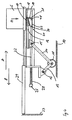
- the partially ejected state (battery replacement position) is in FIG. 3 shown.
- the holding device 7 When pushing out of the holding device 7, the holding device 7 is moved away from the wall 27 of the battery compartment 5.
- the second push rod 22 is moved counter to the removal direction A and the second Wedge element 21 comes into contact with the first wedge element 17. Since the support roller 11 is unloaded, the wedge elements 17, 21 can easily slide in the guide 23 and the joint 15 is also moved against the removal direction A.
- the roller 11 is pressed down over the second articulated arm 14 until it comes into contact with the roadway 10.
- the ground contact of the roller 11 a part of the weight of the battery 6 is transmitted via the roller 11 on the roadway 10.
- the articulated arm 14 is pushed in removal direction A and between the wedge elements 17, 21, the wedge effect occurs. Due to the wave-shaped surfaces 24, 25 engage with each other and reliably prevent further movement of the second wedge member 21 in relation to the guide 23 and thus the holding device 7. Thus, the holding device 7 during the further extension safely through the roller 11 on the roadway 10th supported and relieved the truck.
- the ejected state (battery replacement position) is in FIG. 4 shown.
- the majority of the load of the battery 6 now acts on the roller 11th
- the roller 11 When retracting the holding device 7, the roller 11 also rolls on the road surface 10 and thus supports the holding device 7 until the load is taken over by the guide 8 and the stop 26 comes into contact with the wall 27 of the battery compartment 5.
- the second push rod 22 is pressed counter to the direction of movement B of the holding device 7, so that the wedge effect of the wedge elements 17, 21 is lifted and the second push rod 22 with the tip 30 of the second wedge member 21 opposite side 31 against the stop 19 at the top 18th of the first wedge member 17 abuts.
- the second push rod 22 now also pushes the first push rod 16 and the associated joint 15 in removal direction A, as a result of which the second pivot arm 14 is pivoted upwards and the roller 11 is raised to the operating position.
- the arrangement shown is characterized both by its simple structure, which allows the pivoting in and out of the roller 11 alone by the force of the hydraulic cylinder 29 and the spring 28, and in that even at different distances of the holding device 7 from the roadway 10th , as they may result, for example, due to the degree of wear of the vehicle tires or unevenness of the road surface 10, the roller 11 safely extended and is locked. For example, reduces the distance of the holding device 7 from the road surface 10 due to tire wear, so the roller 11 meets earlier on the roadway 10 and thus previously triggers a lock by blocking the wedge device 20 from. Elaborate drive devices for pivoting the roller 11 and sensors that detect the placement of the roller 11 on the roadway 10 can be saved.
- the push rods 16, 22 are not superimposed on each other but arranged side by side and thus the wedge device 20 is installed practically rotated by 90 °, resulting in a particularly flat structure.
- the single roller 11 other means may be used which allow a simple movement of the supporting device 9 over the ground, for example in the form of a sliding element or several rollers, which can be arranged either side by side or linearly.
- the hydraulic cylinder 29 of course, another drive for the Ausschub conceivable.
Landscapes
- Engineering & Computer Science (AREA)
- Transportation (AREA)
- Mechanical Engineering (AREA)
- Power Engineering (AREA)
- Structural Engineering (AREA)
- Chemical & Material Sciences (AREA)
- Combustion & Propulsion (AREA)
- Civil Engineering (AREA)
- Life Sciences & Earth Sciences (AREA)
- Geology (AREA)
- Forklifts And Lifting Vehicles (AREA)
Abstract
Description
- Die Erfindung betrifft ein Flurförderzeug, insbesondere Gabelstapler, mit einem Fahrzeugrahmen, der eine seitliche Entnahmeöffnung für einen Batterieblock aufweist, wobei für den Batterieblock eine Haltevorrichtung und mindestens eine ausschwenkbare Stützvorrichtung für die Haltevorrichtung vorgesehen ist, wobei die Haltevorrichtung mittels einer Führung zwischen einer Betriebsposition, in der sich die Haltevorrichtung vollständig innerhalb des Fahrzeugrahmens befindet, und einer Batteriewechselposition, in der sich die Haltevorrichtung vollständig außerhalb des Fahrzeugrahmens befindet, bewegbar ist.
- Flurförderzeuge, insbesondere Gegengewichtsgabelstapler, sind vor allem in jüngerer Zeit häufig mit einer seitlichen Batterieentnahmeöffnung ausgeführt. Um den Batterieblock oder eine andere Energieversorgungseinheit, beispielsweise eine Brennstoffzelleneinheit, zu wechseln, wird der im Gabelstapler vorhandene Batterieblock in horizontaler Richtung aus dem Batteriefach des Gabelstaplers heraus bewegt.
- Häufig ist es bei den Betreibern von Gabelstaplern üblich, die Batterieblöcke mittels eines Krans zu transportieren. Um dies bei Gabelstaplern mit einer seitlichen Batterieentnahmeöffnung zu ermöglichen, muss der Batterieblock zunächst vollständig aus dem Batteriefach heraus bewegt werden. Erst dann kann der Batterieblock an den Kran angehängt und angehoben werden. Analog hierzu kann während des Einsetzens in das Batteriefach der Batterieblock mittels des Krans nur neben die Entnahmeöffnung bewegt werden. Um den Batterieblock dann in horizontaler Richtung durch die Entnahmeöffnung in das Batteriefach zu bewegen, bedarf es einer Hilfsvorrichtung.
- Hilfsvorrichtungen, die es erlauben, den Batterieblock ohne Zuhilfenahme eines Gabelhubwagens in horizontaler Richtung in das Batteriefach hinein oder aus dem Batteriefach heraus zu bewegen, sind im Stand der Technik bereits bekannt. In der
DE 102 40 854 A1 ist beispielsweise beschrieben, unten im Batteriefach als Haltevorrichtung für die Batterie bei der Entnahme eine ausziehbare Rollenbahn anzuordnen. Nach dem Ausziehen der Rollenbahn kann der Batterieblock auf der Rollenbahn vollständig aus dem Batteriefach heraus gerollt werden. - Wenn sich die Batterie neben dem Flurförderzeug befindet, liegt ihr gesamtes Gewicht auf der Haltevorrichtung. Ist diese nur am Flurförderzeug befestigt, kann sich der Gesamtschwerpunkt des Fahrzeugs durch das außerhalb der Radbasis befindliche Gewicht der Batterie soweit verschieben, dass das Fahrzeug umzukippen droht. Zudem muss die Entnahmevorrichtung sehr stabil ausgeführt werden, um das Gewicht der Batterie auf das Flurförderzeug übertragen zu können. Daher ist es, beispielsweise aus der
DE 10 2005 025 647 , bekannt, eine an der Führungsvorrichtung angeordnete, auf eine Fahrbahnoberfläche schwenkbare Stützvorrichtung vorzusehen. Ist die Stützvorrichtung abgesenkt, stützt sich die Haltevorrichtung teilweise auf dieser ab, so dass das Flurförderzeug nicht mehr umkippen kann und Kräfte, die auf die Befestigung der Haltevorrichtung am Flurförderzeug wirken, reduziert werden. - Um den Vorgang weitestgehend zu automatisieren, Zeit einzusparen und die Bedienperson von körperlicher Arbeit zu entlasten, kann das Ausschwenken oder Ausfahren der Stützvorrichtung beispielsweise mittels einer Antriebsvorrichtung vorgenommen werden. Elektrische oder hydraulische Antriebsvorrichtungen sind jedoch aufwändig, benötigen eine Energieversorgung, sind fehleranfällig und schwierig zu warten.
- Der Erfindung liegt daher die Aufgabe zugrunde, ein Flurförderzeug gemäß dem Oberbegriff des Anspruchs 1 zur Verfügung zu stellen, das einfach aufgebaut ist und bei dem eine Abstützung der Entnahmevorrichtung und des darauf angeordneten Batterieblocks mit einfachen Mitteln ermöglicht wird.
- Diese Aufgabe wird erfindungsgemäß dadurch gelöst, dass die Stützvorrichtung mittels Federkraft und/oder Gewichtskraft von einer angehobenen in eine abgesenkte Stellung bewegbar ist und mindestens eine Vorrichtung zur selbsttätigen Arretierung der Stützvorrichtung in der abgesenkten Stellung vorgesehen ist. Indem die Stützvorrichtung mittels Federkraft und/oder Gewichtskraft absenkbar ist, ist keine externe Energieversorgung notwendig. Ein Federantrieb ist einfach aufgebaut, wartungsfrei, einfach gegen Überlastung abzusichern und kostengünstig herstellbar. Im Zusammenspiel von Gewichtskraft und Federkraft wird mit besonders hoher Sicherheit gewährleistet, dass die Stütze wirklich abgesenkt wird. Eine selbsttätige Arretierung in der abgesenkten Stellung ist dabei besonders vorteilhaft, weil so das Stützelement gegen unbeabsichtigtes Verschwenken, insbesondere Einfahren, abgesichert wird, ohne dass die Bedienperson durch Einsetzen oder Lösen der Arretierung eingreifen muss. Dabei sind Ausführungsformen zu bevorzugen, bei denen der Federantrieb die zur Arretierung erforderlichen Kräfte nicht oder nur zu geringen Teilen aufbringen muss.
- Es ist von besonderem Vorteil, wenn die Vorrichtung zur Arretierung der Stützvorrichtung in der abgesenkten Stellung als Keilvorrichtung ausgebildet ist. Keilvorrichtungen erlauben eine einfache Fixierung von beweglichen Teilen, bei denen sich die Stärke der Fixierung mit zunehmendem Weg erhöht. Eine Lösung der Fixierung ist mit geringem einmaligem Kraftaufwand und sehr kurzem Verstellweg möglich.
- Weiterhin ist es von besonderem Vorteil, wenn die Keilvorrichtung so ausgebildet ist, dass die Kräfte zur Erzielung der Keilwirkung durch die Gewichtskraft der Batterie und/oder der Haltevorrichtung aufbringbar sind. Damit kann auf aufwändige Vorrichtungen, die die Kräfte zur Arretierung der Stützvorrichtung aufbringen, verzichtet werden. Bei zunehmendem Gewicht, beispielsweise bei Verwendung einer schwereren Batterie, wird auch die Arretierungswirkung erhöht. Die Kraft zum Lösen der Arretierung ist damit auch vom Gewicht der Batterie abhängig, so dass bei leichten Batterien keine unnötig großen Kräfte aufgebracht werden müssen.
- Es ist zweckmäßig, wenn die ausschwenkbare Stützvorrichtung mindestens einen ersten, an der Haltevorrichtung schwenkbar angeordneten Gelenkarm mit einer an dem schwenkbar angeordneten Arm drehbar gelagerten Rolle aufweist. Eine Rolle ermöglicht eine problemlose seitliche Bewegung der Haltevorrichtung.
- Es ist ebenfalls zweckmäßig, wenn die ausschwenkbare Stützvorrichtung mindestens einen zweiten Gelenkarm zwischen der Rolle und einer ersten parallel zur Ausschubrichtung bewegbaren Schubstange aufweist. Durch Bewegung der Schubstange ist die Rolle anheb- beziehungsweise absenkbar,
- Indem die erste Schubstange ein erstes keilförmiges Element aufweist, dessen Keilspitze in die Bewegungsrichtung der Schubstange von der Rolle weg ausgerichtet ist, ist eine Bewegung der Schubstange in diese Richtung blockierbar und somit die Rolle in ihrer Position arretierbar.
- Es ist weiterhin Vorteil, wenn eine zweite, parallel zur Ausschubrichtung bewegbare Schubstange vorgesehen ist, die ein zweites keilförmiges Element aufweist, das mit dem ersten keilförmigen Element in Eingriff bringbar ist. Durch Bewegung der Schubstangen in gegenläufige Richtungen ist die Keilvorrichtung und damit das Stützelement arretierbar.
- Ebenso ist es vorteilhaft, wenn die keilförmigen Elemente in einer Führung mit vorzugsweise rechteckigem Querschnitt gelagert sind. Eine derartige Führung ist eine besonders einfache Möglichkeit, die keilförmigen Elemente sowohl zu führen als auch die Keilwirkung durch eine Kraft annähernd senkrecht zur Bewegungsrichtung der Schubstangen herbeizuführen.
- Es ist ebenso vorteilhaft, wenn mindestens eine der Schubstangen, vorzugsweise die zweite Schubstange, mittels Federkraft entgegen der Ausschubrichtung der Batterie von einer vollständig eingeschobenen Position (Betriebsposition) in eine vollständig ausgeschobene Position (Batteriewechselposition) bewegbar ist. Damit ist eine besonders einfache Möglichkeit der Bewegung einer oder beider Schubstangen möglich, die als Antrieb für das Ausschwenken der Stützvorrichtung dient.
- Weiterhin ist es von Vorteil, wenn mindestens eines der keilförmigen Elemente an der der Keilfläche abgewandten Seitenfläche ein wellenförmiges Profil aufweist und die Führung der keilförmigen Elemente an der der Seitenfläche zugewandten Fläche ein annähernd gleichartiges wellenförmiges Profil aufweist. Dadurch wird ein Verrutschen der Keile sowohl untereinander als auch gemeinsam in Relation zu der Führung zuverlässig verhindert.
- Vorteilhafterweise weist die erste Schubstange, vorzugsweise an der Keilspitze des ersten keilförmigen Elements, einen Anschlag auf, an welchen ein Teil der zweiten Schubstange, vorzugsweise der der Keilspitze abgewandte Teil des zweiten keilförmigen Elements, durch eine entgegen der Keilwirkung gerichtete Relativbewegung der Schubstangen in Kontakt bringbar ist. Dadurch ist bei einer Bewegung, die zum Lösen der Keilwirkung führt, eine Mitnahme der ersten Schubstange durch die zweite Schubstange möglich, die beispielsweise zum Einschwenken der Stützvorrichtung führt.
- Weitere Vorteile und Einzelheiten der Erfindung werden anhand des in den schematischen Figuren dargestellten Ausführungsbeispiels näher erläutert. Gleiche Teile sind mit gleichen Bezugszeichen gekennzeichnet. Dabei zeigt
- Figur 1
- einen erfindungsgemäßen Gabelstapler in Seitenansicht,
- Figur 2
- schematisch die Führung für die Haltevorrichtung in eingeschobener Stellung (Betriebsposition),
- Figur 3
- schematisch die Führung für die Haltevorrichtung in teilweise ausgezogener Stellung,
- Figur 4
- schematisch die Führung für die Haltevorrichtung in vollständig ausgezogener Stellung (Batteriewechselposition).
-
Figur 1 zeigt einen erfindungsgemäßen Gabelstapler in Seitenansicht. Das tragende Element des Gabelstaplers ist ein Fahrzeugrahmen 1. Vorne am Gabelstapler ist ein Hubgerüst 2 mit einem nach oben und unten bewegbaren Lastaufnahmemittel 3 befestigt. Am hinteren Ende des Gabelstaplers befindet sich ein Heckgewicht 4. - In einem Freiraum des Fahrzeugrahmens befindet sich ein seitlich offenes Batteriefach 5, in dem ein Batterieblock 6 angeordnet ist. Der Batterieblock 6 steht auf einer Haltevorrichtung 7 auf, welche mittels einer teleskopischen Führung 8 in seitlicher Richtung aus dem Batteriefach 5 heraus bewegt werden kann.
- An der Haltevorrichtung 7 ist eine ausschwenkbare Stützevorrichtung 9 befestigt. Solange sich die Haltevorrichtung 7 in der Betriebsposition innerhalb des Fahrzeugrahmens 1 befindet, ist die Stützvorrichtung 9 eingeschwenkt und befindet sich innerhalb der Fahrzeugkontur. Sobald die Stützvorrichtung 9 aus dem Fahrzeug heraus bewegt wird, wird sie selbsttätig ausgeschwenkt und stützt die Gewichtskraft des Batterieblocks 6 direkt an der Fahrbahn 10 ab. Am unteren Ende der Stützvorrichtung 9 befindet sich eine Rolle 11, die während der Ausfahrbewegung auf der Fahrbahn 10 abrollt.
- In
Figur 2 ist schematisch die Führung 8 der eingeschobenen Haltevorrichtung 7 in Seitenansicht dargestellt. An der Haltevorrichtung 7 mit der Batterie 6 ist über ein Gelenk 12 und einen ersten Gelenkarm 13 die Rolle 11 befestigt. Ein zweiter Gelenkarm 14 und ein Gelenk 15 verbinden die Rolle 11 mit einer ersten Schubstange 16, die in Relation zu der Haltevorrichtung 7 parallel zur Ausschubrichtung A der Batterie 6 beweglich gelagert ist. Am Ende der ersten Schubstange 16 ist ein erstes Keilelement 17 angeordnet, dessen Spitze 18 in Bewegungsrichtung A der Schubstange 16 gesehen von der Rolle 11 wegzeigt. An der Spitze 18 des ersten Keilelements 17 ist ein Anschlag 19 angebracht. - Die erfindungsgemäße Keilvorrichtung 20 umfasst weiterhin ein zweites Keilelement 21, das an einer zweiten Schubstange 22 angebracht ist. Geführt werden die beiden Keilelemente 17, 21 in einer Führung 23 mit rechteckigem Querschnitt, die an der Haltevorrichtung 7 befestigt ist. Die Unterseite 24 des zweiten Keilelements 21 weist ein wellenförmiges Profil auf. Die der Unterseite 24 des zweiten Keilelements zugewandte Seite 25 der Führung 23 weist ein annähernd identisches Profil auf. Dies bewirkt, dass Bewegungen des zweiten Keilelements 21 in Relation zu der Führung 23 bei Eintreten der Keilwirkung zuverlässig unterbunden werden.
- An der dem zweiten Keilelement 21 abgewandten Seite der zweiten Schubstange 22 ist ein Anschlag 26 angeordnet, der in der Betriebsposition der Haltevorrichtung 7 an einem fest mit dem Rahmen 1 des Flurförderzeugs verbundenen Bauteil, beispielsweise einer Wand 27 des Batteriefachs 5, in Kontakt steht. Zwischen Anschlag 26 und Haltevorrichtung 7 ist auf der zweiten Schubstange 22 eine Schraubenfeder 28 angeordnet. Die Schraubenfeder 28 ist bei eingeschobener Haltevorrichtung 7 (Betriebsposition) maximal komprimiert. Mittels eines doppeltwirkenden Hydraulikzylinders 29, der zwischen dem Rahmen 1 des Flurförderzeugs und der Haltevorrichtung 7 angebracht ist, kann die Haltevorrichtung 7 seitwärts in Richtung des Pfeils A aus dem Flurförderzeug herausbewegt werden.
- Der teilweise ausgeschobene Zustand (Batteriewechselposition) ist in
Figur 3 dargestellt. Beim Ausschieben der Haltevorrichtung 7 wird die Haltevorrichtung 7 von der Wand 27 des Batteriefachs 5 wegbewegt. Durch die Federkraft der Feder 28 wird die zweite Schubstange 22 entgegen der Entnahmerichtung A bewegt und das zweite Keilelement 21 gelangt in Kontakt zum ersten Keilelement 17. Da die Stützrolle 11 unbelastet ist, können die Keilelemente 17, 21 leicht in der Führung 23 gleiten und das Gelenk 15 wird ebenfalls entgegen der Entnahmerichtung A bewegt. Dadurch wird über den zweiten Gelenkarm 14 die Rolle 11 nach unten gedrückt, bis diese in Kontakt mit der Fahrbahn 10 kommt. Durch den Bodenkontakt der Rolle 11 wird ein Teil der Gewichtskraft der Batterie 6 über die Rolle 11 auf die Fahrbahn 10 übertragen. Dadurch wird der Gelenkarm 14 in Entnahmerichtung A geschoben und zwischen den Keilelementen 17, 21 tritt die Keilwirkung ein. Aufgrund der wellenförmigen Oberflächen 24, 25 greifen diese ineinander und verhindern zuverlässig eine weitere Bewegung des zweiten Keilelements 21 in Relation zu der Führung 23 und damit der Haltevorrichtung 7. Damit wird die Haltevorrichtung 7 während des weiteren Ausfahrvorgangs sicher durch die Rolle 11 auf der Fahrbahn 10 abgestützt und das Flurförderzeug entlastet. - Der ausgeschobene Zustand (Batteriewechselposition) ist in
Figur 4 dargestellt. Der Großteil der Last der Batterie 6 wirkt nun auf die Rolle 11. - Beim Einfahren der Haltevorrichtung 7 rollt die Rolle 11 ebenfalls auf der Fahrbahn 10 ab und stützt so die Haltevorrichtung 7 bis die Last von der Führung 8 übernommen wird und der Anschlag 26 in Kontakt mit der Wand 27 des Batteriefachs 5 kommt. Die zweite Schubstange 22 wird entgegen der Bewegungsrichtung B der Haltevorrichtung 7 gedrückt, so dass die Keilwirkung der Keilelemente 17, 21 aufgehoben wird und die zweite Schubstange 22 mit der der Spitze 30 des zweiten Keilelements 21 abgewandten Seite 31 gegen den Anschlag 19 an der Spitze 18 des ersten Keilelements 17 stößt. Dadurch drückt die zweite Schubstange 22 nun auch die erste Schubstange 16 und das damit verbundene Gelenk 15 in Entnahmerichtung A, wodurch der zweite Schwenkarm 14 nach oben geschwenkt wird und die Rolle 11 in die Betriebsposition angehoben wird.
- Die gezeigte Anordnung zeichnet sich sowohl durch ihren einfachen Aufbau aus, der das Ein- und Ausschwenken der Rolle 11 alleine durch die Kraft des Hydraulikzylinders 29 beziehungsweise der Feder 28 ermöglicht, als auch darin, dass auch bei unterschiedlichen Abständen der Haltevorrichtung 7 von der Fahrbahn 10, wie sie sich beispielsweise aufgrund des Abnutzungsgrades der Fahrzeugreifen oder Unebenheiten der Fahrbahn 10 ergeben können, die Rolle 11 sicher ausgefahren und arretiert wird. Verringert sich beispielsweise der Abstand der Haltevorrichtung 7 von der Fahrbahn 10 aufgrund von Reifenverschleiß, so trifft die Rolle 11 früher auf der Fahrbahn 10 auf und löst damit früher eine Arretierung durch Blockieren der Keilvorrichtung 20 aus. Aufwändige Antriebsvorrichtungen für das Ausschwenken der Rolle 11 sowie Sensoren, die das Aufsetzen der Rolle 11 auf der Fahrbahn 10 detektieren, können so eingespart werden.
- Selbstverständlich sind auch andere Ausführungsformen der Erfindung denkbar, indem beispielsweise die Schubstangen 16, 22 nicht übereinander sonder nebeneinander angeordnet werden und somit auch die Keilvorrichtung 20 praktisch um 90 ° gedreht eingebaut ist, was einen besonders flachen Aufbau ergibt. Anstelle der einzelnen Rolle 11 könne auch andere Mittel verwendet werden ,die eine einfache Bewegung der Stützvorrichtung 9 über den Boden erlauben, beispielsweise in Form eines Gleitelements oder mehrerer Rollen, die entweder nebeneinander oder linear angeordnet werden können. Anstelle des Hydraulikzylinders 29 ist selbstverständlich auch ein anderer Antrieb für den Ausschub denkbar.
Claims (11)
- Flurförderzeug , insbesondere Gabelstapler, mit einem Fahrzeugrahmen (1), der eine seitliche Entnahmeöffnung für einen Batterieblock (6) aufweist, wobei für den Batterieblock (6) eine Haltevorrichtung (7) und mindestens eine ausschwenkbare Stützvorrichtung (9) für die Haltevorrichtung (7) vorgesehen ist, wobei die Haltevorrichtung (7) mittels einer Führung (8) zwischen einer Betriebsposition, in der sich die Haltevorrichtung (7) vollständig innerhalb des Fahrzeugrahmens (1) befindet, und einer Batteriewechselposition, in der sich die Haltevorrichtung (7) vollständig außerhalb des Fahrzeugrahmens (1) befindet, bewegbar ist, dadurch gekennzeichnet, dass die Stützvorrichtung (9) mittels Federkraft und/oder Gewichtskraft von einer angehobenen in eine abgesenkte Stellung bewegbar ist und mindestens eine Vorrichtung (20) zur selbsttätigen Arretierung der Stützvorrichtung (9) in der abgesenkten Stellung vorgesehen ist.
- Flurförderzeug nach Anspruch 1, dadurch gekennzeichnet, dass die Vorrichtung (20) zur Arretierung der Stützvorrichtung (9) in der abgesenkten Stellung als Keilvorrichtung (20) ausgebildet ist.
- Flurförderzeug nach Anspruch 1 oder 2, dadurch gekennzeichnet, dass die Keilvorrichtung (20) derart ausgebildet ist, dass die Kräfte zur Erzielung der Keilwirkung durch die Gewichtskraft der Batterie (6) und/oder der Haltevorrichtung (7) aufbringbar sind.
- Flurförderzeug nach einem der Ansprüche 1 bis 3, dadurch gekennzeichnet, dass die ausschwenkbare Stützvorrichtung (9) mindestens einen ersten, an der Haltevorrichtung (7) schwenkbar angeordneten Gelenkarm (13) mit einer an dem schwenkbar angeordneten Gelenkarm (13) drehbar gelagerten Rolle (11) aufweist.
- Flurförderzeug nach einem der Ansprüche 1 bis 4, dadurch gekennzeichnet, dass die ausschwenkbare Stützvorrichtung (9) mindestens einen zweiten Gelenkarm (14) zwischen der Rolle (11) und einer ersten parallel zur Ausschubrichtung A bewegbaren Schubstange (16) aufweist.
- Flurförderzeug nach einem der Ansprüche 1 bis 5, dadurch gekennzeichnet, dass die erste Schubstange (16) ein erstes keilförmiges Element (17) aufweist, dessen Keilspitze (18) in die Bewegungsrichtung der Schubstange (16) von der Rolle (11) weg ausgerichtet ist.
- Flurförderzeug nach einem der Ansprüche 1 bis 6, dadurch gekennzeichnet, dass eine zweite, parallel zur Ausschubrichtung bewegbare Schubstange (22) vorgesehen ist, die ein zweites keilförmiges Element (21) aufweist, das mit dem ersten keilförmigen Element (17) in Eingriff bringbar ist.
- Flurförderzeug nach einem der Ansprüche 1 bis 7, dadurch gekennzeichnet, dass die keilförmigen Elemente (17, 21) in einer Führung (20) mit vorzugsweise rechteckigem Querschnitt gelagert sind.
- Flurförderzeug nach einem der Ansprüche 1 bis 8, dadurch gekennzeichnet, dass mindestens eine der Schubstangen (16, 22), vorzugsweise die zweite Schubstange (22), mittels Federkraft entgegen der Ausschubrichtung der Batterie (6) von einer vollständig eingeschobenen Position (Betriebsposition) in eine vollständig ausgeschobene Position (Batteriewechselposition) bewegbar ist.
- Flurförderzeug nach einem der Ansprüche 1 bis 9, dadurch gekennzeichnet, dass mindestens eines der keilförmigen Elemente (17, 21) an der der Keilfläche abgewandten Seitenfläche (24) ein wellenförmiges Profil aufweist und die Führung (23) der keilförmigen Elemente (17, 21) an der der Seitenfläche zugewandten Fläche (25) ein annähernd gleichartiges wellenförmiges Profil aufweist.
- Flurförderzeug nach einem der Ansprüche 1 bis 10, dadurch gekennzeichnet, dass die erste Schubstange (16), vorzugsweise an der Keilspitze (18) des ersten keilförmigen Elements (17), einen Anschlag (19) aufweist, an welchen ein Teil der zweiten Schubstange (22), vorzugsweise der der Keilspitze (30) abgewandte Teil (31) des zweiten keilförmigen Elements (21), durch eine entgegen der Keilwirkung gerichtete Relativbewegung der Schubstangen (17, 22) in Kontakt bringbar ist.
Applications Claiming Priority (1)
| Application Number | Priority Date | Filing Date | Title |
|---|---|---|---|
| DE102006061071A DE102006061071A1 (de) | 2006-12-22 | 2006-12-22 | Gabelstapler mit einer Führung zur seitlichen Batterieentnahme |
Publications (3)
| Publication Number | Publication Date |
|---|---|
| EP1935731A2 true EP1935731A2 (de) | 2008-06-25 |
| EP1935731A3 EP1935731A3 (de) | 2012-10-31 |
| EP1935731B1 EP1935731B1 (de) | 2013-11-13 |
Family
ID=39105912
Family Applications (1)
| Application Number | Title | Priority Date | Filing Date |
|---|---|---|---|
| EP07023264.0A Not-in-force EP1935731B1 (de) | 2006-12-22 | 2007-11-30 | Gabelstapler mit einer Führung zur seitlichen Batterieentnahme |
Country Status (2)
| Country | Link |
|---|---|
| EP (1) | EP1935731B1 (de) |
| DE (1) | DE102006061071A1 (de) |
Cited By (7)
| Publication number | Priority date | Publication date | Assignee | Title |
|---|---|---|---|---|
| FR2955296A1 (fr) * | 2010-01-18 | 2011-07-22 | Peugeot Citroen Automobiles Sa | Vehicule electrique ou partiellement electrique equipe d'un dispositif permettant de faciliter le remplacement de son dispositif de stockage d'energie electrique |
| EP2392540A1 (de) * | 2010-06-04 | 2011-12-07 | Linde Material Handling GmbH | Flurförderzeug |
| DE102012105456A1 (de) | 2012-06-22 | 2013-12-24 | Still Gmbh | Flurförderzeug mit einem seitlichen Wechsel einer Energieversorgungseinheit |
| CN105564392A (zh) * | 2015-12-10 | 2016-05-11 | 宋焕炜 | 新能源汽车电源更替设施 |
| US9783076B2 (en) | 2014-09-18 | 2017-10-10 | Zhejiang Geely Holding Group Co., Ltd | Electric vehicle |
| CN112993467A (zh) * | 2018-08-21 | 2021-06-18 | 赵海霞 | 一种新能源汽车电池组机构 |
| CN119461165A (zh) * | 2024-11-06 | 2025-02-18 | 杭叉集团股份有限公司 | 一种叉车动力电池自动更换系统 |
Families Citing this family (5)
| Publication number | Priority date | Publication date | Assignee | Title |
|---|---|---|---|---|
| DE102008032305B4 (de) | 2008-07-09 | 2022-11-24 | Linde Material Handling Gmbh | Flurförderzeug |
| DE102008034431B4 (de) * | 2008-07-24 | 2015-01-08 | Jungheinrich Aktiengesellschaft | Batteriewagen zur Aufnahme eines Batterietrogs für ein Flurförderzeug |
| DE102013216399A1 (de) * | 2013-08-19 | 2015-02-19 | Jungheinrich Aktiengesellschaft | Batteriebetriebenes Arbeitsfahrzeug, insbesondere Flurförderzeug |
| DE102014012463B4 (de) | 2014-08-21 | 2020-06-04 | Diehl Defence Gmbh & Co. Kg | Vorrichtung zur Unterflur-Montage eines Generators an einem Kraftfahrzeug |
| CN109910673A (zh) * | 2019-02-26 | 2019-06-21 | 深圳市辉腾创新科技有限公司 | 一种电动汽车换电站浮动式精准定位装置 |
Family Cites Families (4)
| Publication number | Priority date | Publication date | Assignee | Title |
|---|---|---|---|---|
| JPS59105298U (ja) * | 1982-12-30 | 1984-07-16 | 株式会社豊田自動織機製作所 | リ−チ式バツテリフオ−クリフトのバツテリストツパ |
| JPH0549441U (ja) * | 1991-12-17 | 1993-06-29 | 小松フォークリフト株式会社 | フォークリフトトラックのバッテリー出し入れ装置 |
| JPH08165094A (ja) * | 1994-12-09 | 1996-06-25 | Nippon Yusoki Co Ltd | 産業車両のバッテリーテーブル |
| DE102005022094A1 (de) * | 2005-05-12 | 2006-11-16 | Still Gmbh | Flurförderzeug mit einem seitlich ausziehbaren Batterieblock |
-
2006
- 2006-12-22 DE DE102006061071A patent/DE102006061071A1/de not_active Withdrawn
-
2007
- 2007-11-30 EP EP07023264.0A patent/EP1935731B1/de not_active Not-in-force
Cited By (10)
| Publication number | Priority date | Publication date | Assignee | Title |
|---|---|---|---|---|
| FR2955296A1 (fr) * | 2010-01-18 | 2011-07-22 | Peugeot Citroen Automobiles Sa | Vehicule electrique ou partiellement electrique equipe d'un dispositif permettant de faciliter le remplacement de son dispositif de stockage d'energie electrique |
| EP2392540A1 (de) * | 2010-06-04 | 2011-12-07 | Linde Material Handling GmbH | Flurförderzeug |
| DE102012105456A1 (de) | 2012-06-22 | 2013-12-24 | Still Gmbh | Flurförderzeug mit einem seitlichen Wechsel einer Energieversorgungseinheit |
| US9783076B2 (en) | 2014-09-18 | 2017-10-10 | Zhejiang Geely Holding Group Co., Ltd | Electric vehicle |
| CN105564392A (zh) * | 2015-12-10 | 2016-05-11 | 宋焕炜 | 新能源汽车电源更替设施 |
| CN112993467A (zh) * | 2018-08-21 | 2021-06-18 | 赵海霞 | 一种新能源汽车电池组机构 |
| CN112993468A (zh) * | 2018-08-21 | 2021-06-18 | 赵海霞 | 一种新能源汽车电池组机构的工作方法 |
| CN112993467B (zh) * | 2018-08-21 | 2022-09-02 | 宁波宏德众悦科技股份有限公司 | 一种新能源汽车电池组机构 |
| CN112993468B (zh) * | 2018-08-21 | 2022-11-22 | 常州麦塔科技有限公司 | 一种新能源汽车电池组机构的工作方法 |
| CN119461165A (zh) * | 2024-11-06 | 2025-02-18 | 杭叉集团股份有限公司 | 一种叉车动力电池自动更换系统 |
Also Published As
| Publication number | Publication date |
|---|---|
| EP1935731B1 (de) | 2013-11-13 |
| DE102006061071A1 (de) | 2008-06-26 |
| EP1935731A3 (de) | 2012-10-31 |
Similar Documents
| Publication | Publication Date | Title |
|---|---|---|
| EP1935731B1 (de) | Gabelstapler mit einer Führung zur seitlichen Batterieentnahme | |
| EP0011250B1 (de) | Fahrzeug zum Laden und Transportieren von Schwergut, insbesondere von Kraftfahrzeugen | |
| EP3013728B1 (de) | Hebevorrichtung zum heben und senken von fahrzeugen | |
| EP1415874B1 (de) | Batteriewechselsystem für ein Flurförderzeug | |
| EP1396466B1 (de) | Flurförderzeug mit einer seitlichen Batterieentnahmeöffnung | |
| DE9418354U1 (de) | Lastklemmvorrichtung mit erweitertem vertikalem Bewegungsbereich | |
| EP3609833B1 (de) | Hebebühne zum anheben von fahrzeugen | |
| DE102018112568A1 (de) | Flurförderzeug mit aus- und einfahrbarem Zusatzrad | |
| EP1925588B1 (de) | Gabelstapler mit einer Führung zum seitlichen Ausziehen eines Batterieblocks | |
| DE3620964C2 (de) | ||
| EP2065334B1 (de) | Kippmechanismus für ein Hubgerüst eines Flurförderzeugs und Transportverfahren für ein Flurförderzeug | |
| EP2953887B1 (de) | Vorrichtung zur aufnahme und zum transport von lasten | |
| DE4110489A1 (de) | Palettentransportgeraet | |
| DE102010050930B4 (de) | Mobile Hebebühne sowie Verfahren zur Überwachung eines Fahrwerks der mobilen Hebebühne | |
| DE19938727A1 (de) | Hebe- und Ladevorrichtung | |
| DE20020741U1 (de) | Kommissionierfahrzeug | |
| AT522493A2 (de) | Fahrbare Hubeinrichtung in Leichtbau | |
| EP1122207B1 (de) | Schwenkschubgabel | |
| DE102010026743A1 (de) | Hubladebühne und Verfahren zum Betrieb einer an einem Fahrzeug angeordneten Hubladebühne | |
| DE102018112567A1 (de) | Flurförderzeug mit Hubgerüst | |
| DE4323328A1 (de) | Anbaugerät für Flurförderzeuge | |
| EP0438998A2 (de) | Transportwagen, insbesondere Niederflurwagen, sowie ein Verfahren zum Be- und Entladen desselben | |
| DE102019001681B4 (de) | Fahrzeug und Rampe hierfür | |
| DE102017110215A1 (de) | Stempelbühne für Fahrzeuge sowie Hubeinrichtung für Stempelbühne | |
| EP2128076B1 (de) | Hubanordnung für ein Flurförderzeug |
Legal Events
| Date | Code | Title | Description |
|---|---|---|---|
| PUAI | Public reference made under article 153(3) epc to a published international application that has entered the european phase |
Free format text: ORIGINAL CODE: 0009012 |
|
| AK | Designated contracting states |
Kind code of ref document: A2 Designated state(s): AT BE BG CH CY CZ DE DK EE ES FI FR GB GR HU IE IS IT LI LT LU LV MC MT NL PL PT RO SE SI SK TR |
|
| AX | Request for extension of the european patent |
Extension state: AL BA HR MK RS |
|
| PUAL | Search report despatched |
Free format text: ORIGINAL CODE: 0009013 |
|
| AK | Designated contracting states |
Kind code of ref document: A3 Designated state(s): AT BE BG CH CY CZ DE DK EE ES FI FR GB GR HU IE IS IT LI LT LU LV MC MT NL PL PT RO SE SI SK TR |
|
| AX | Request for extension of the european patent |
Extension state: AL BA HR MK RS |
|
| RIC1 | Information provided on ipc code assigned before grant |
Ipc: B66F 9/075 20060101ALI20120926BHEP Ipc: B60S 5/06 20060101AFI20120926BHEP Ipc: B60K 1/04 20060101ALI20120926BHEP Ipc: B60L 11/18 20060101ALI20120926BHEP |
|
| 17P | Request for examination filed |
Effective date: 20130418 |
|
| AKX | Designation fees paid |
Designated state(s): AT BE BG CH CY CZ DE DK EE ES FI FR GB GR HU IE IS IT LI LT LU LV MC MT NL PL PT RO SE SI SK TR |
|
| GRAP | Despatch of communication of intention to grant a patent |
Free format text: ORIGINAL CODE: EPIDOSNIGR1 |
|
| RIC1 | Information provided on ipc code assigned before grant |
Ipc: B60S 5/06 20060101AFI20130711BHEP Ipc: B60K 1/04 20060101ALI20130711BHEP Ipc: B60L 11/18 20060101ALI20130711BHEP Ipc: B66F 9/075 20060101ALI20130711BHEP |
|
| INTG | Intention to grant announced |
Effective date: 20130731 |
|
| GRAS | Grant fee paid |
Free format text: ORIGINAL CODE: EPIDOSNIGR3 |
|
| GRAA | (expected) grant |
Free format text: ORIGINAL CODE: 0009210 |
|
| AK | Designated contracting states |
Kind code of ref document: B1 Designated state(s): AT BE BG CH CY CZ DE DK EE ES FI FR GB GR HU IE IS IT LI LT LU LV MC MT NL PL PT RO SE SI SK TR |
|
| REG | Reference to a national code |
Ref country code: GB Ref legal event code: FG4D Free format text: NOT ENGLISH |
|
| REG | Reference to a national code |
Ref country code: CH Ref legal event code: EP |
|
| REG | Reference to a national code |
Ref country code: AT Ref legal event code: REF Ref document number: 640434 Country of ref document: AT Kind code of ref document: T Effective date: 20131215 |
|
| REG | Reference to a national code |
Ref country code: IE Ref legal event code: FG4D Free format text: LANGUAGE OF EP DOCUMENT: GERMAN |
|
| REG | Reference to a national code |
Ref country code: DE Ref legal event code: R096 Ref document number: 502007012492 Country of ref document: DE Effective date: 20140109 |
|
| REG | Reference to a national code |
Ref country code: NL Ref legal event code: VDEP Effective date: 20131113 |
|
| REG | Reference to a national code |
Ref country code: LT Ref legal event code: MG4D |
|
| PG25 | Lapsed in a contracting state [announced via postgrant information from national office to epo] |
Ref country code: SE Free format text: LAPSE BECAUSE OF FAILURE TO SUBMIT A TRANSLATION OF THE DESCRIPTION OR TO PAY THE FEE WITHIN THE PRESCRIBED TIME-LIMIT Effective date: 20131113 Ref country code: NL Free format text: LAPSE BECAUSE OF FAILURE TO SUBMIT A TRANSLATION OF THE DESCRIPTION OR TO PAY THE FEE WITHIN THE PRESCRIBED TIME-LIMIT Effective date: 20131113 Ref country code: FI Free format text: LAPSE BECAUSE OF FAILURE TO SUBMIT A TRANSLATION OF THE DESCRIPTION OR TO PAY THE FEE WITHIN THE PRESCRIBED TIME-LIMIT Effective date: 20131113 Ref country code: IS Free format text: LAPSE BECAUSE OF FAILURE TO SUBMIT A TRANSLATION OF THE DESCRIPTION OR TO PAY THE FEE WITHIN THE PRESCRIBED TIME-LIMIT Effective date: 20140313 Ref country code: LT Free format text: LAPSE BECAUSE OF FAILURE TO SUBMIT A TRANSLATION OF THE DESCRIPTION OR TO PAY THE FEE WITHIN THE PRESCRIBED TIME-LIMIT Effective date: 20131113 |
|
| PG25 | Lapsed in a contracting state [announced via postgrant information from national office to epo] |
Ref country code: LV Free format text: LAPSE BECAUSE OF FAILURE TO SUBMIT A TRANSLATION OF THE DESCRIPTION OR TO PAY THE FEE WITHIN THE PRESCRIBED TIME-LIMIT Effective date: 20131113 Ref country code: ES Free format text: LAPSE BECAUSE OF FAILURE TO SUBMIT A TRANSLATION OF THE DESCRIPTION OR TO PAY THE FEE WITHIN THE PRESCRIBED TIME-LIMIT Effective date: 20131113 Ref country code: CY Free format text: LAPSE BECAUSE OF FAILURE TO SUBMIT A TRANSLATION OF THE DESCRIPTION OR TO PAY THE FEE WITHIN THE PRESCRIBED TIME-LIMIT Effective date: 20131113 |
|
| BERE | Be: lapsed |
Owner name: STILL G.M.B.H. Effective date: 20131130 |
|
| PG25 | Lapsed in a contracting state [announced via postgrant information from national office to epo] |
Ref country code: PT Free format text: LAPSE BECAUSE OF FAILURE TO SUBMIT A TRANSLATION OF THE DESCRIPTION OR TO PAY THE FEE WITHIN THE PRESCRIBED TIME-LIMIT Effective date: 20140313 |
|
| REG | Reference to a national code |
Ref country code: CH Ref legal event code: PL |
|
| PG25 | Lapsed in a contracting state [announced via postgrant information from national office to epo] |
Ref country code: EE Free format text: LAPSE BECAUSE OF FAILURE TO SUBMIT A TRANSLATION OF THE DESCRIPTION OR TO PAY THE FEE WITHIN THE PRESCRIBED TIME-LIMIT Effective date: 20131113 Ref country code: LI Free format text: LAPSE BECAUSE OF NON-PAYMENT OF DUE FEES Effective date: 20131130 Ref country code: CH Free format text: LAPSE BECAUSE OF NON-PAYMENT OF DUE FEES Effective date: 20131130 |
|
| REG | Reference to a national code |
Ref country code: DE Ref legal event code: R097 Ref document number: 502007012492 Country of ref document: DE |
|
| REG | Reference to a national code |
Ref country code: IE Ref legal event code: MM4A |
|
| PG25 | Lapsed in a contracting state [announced via postgrant information from national office to epo] |
Ref country code: MC Free format text: LAPSE BECAUSE OF FAILURE TO SUBMIT A TRANSLATION OF THE DESCRIPTION OR TO PAY THE FEE WITHIN THE PRESCRIBED TIME-LIMIT Effective date: 20131113 Ref country code: CZ Free format text: LAPSE BECAUSE OF FAILURE TO SUBMIT A TRANSLATION OF THE DESCRIPTION OR TO PAY THE FEE WITHIN THE PRESCRIBED TIME-LIMIT Effective date: 20131113 Ref country code: PL Free format text: LAPSE BECAUSE OF FAILURE TO SUBMIT A TRANSLATION OF THE DESCRIPTION OR TO PAY THE FEE WITHIN THE PRESCRIBED TIME-LIMIT Effective date: 20131113 Ref country code: RO Free format text: LAPSE BECAUSE OF FAILURE TO SUBMIT A TRANSLATION OF THE DESCRIPTION OR TO PAY THE FEE WITHIN THE PRESCRIBED TIME-LIMIT Effective date: 20131113 Ref country code: SK Free format text: LAPSE BECAUSE OF FAILURE TO SUBMIT A TRANSLATION OF THE DESCRIPTION OR TO PAY THE FEE WITHIN THE PRESCRIBED TIME-LIMIT Effective date: 20131113 |
|
| PLBE | No opposition filed within time limit |
Free format text: ORIGINAL CODE: 0009261 |
|
| STAA | Information on the status of an ep patent application or granted ep patent |
Free format text: STATUS: NO OPPOSITION FILED WITHIN TIME LIMIT |
|
| PG25 | Lapsed in a contracting state [announced via postgrant information from national office to epo] |
Ref country code: BE Free format text: LAPSE BECAUSE OF NON-PAYMENT OF DUE FEES Effective date: 20131130 Ref country code: DK Free format text: LAPSE BECAUSE OF FAILURE TO SUBMIT A TRANSLATION OF THE DESCRIPTION OR TO PAY THE FEE WITHIN THE PRESCRIBED TIME-LIMIT Effective date: 20131113 |
|
| 26N | No opposition filed |
Effective date: 20140814 |
|
| GBPC | Gb: european patent ceased through non-payment of renewal fee |
Effective date: 20140213 |
|
| PG25 | Lapsed in a contracting state [announced via postgrant information from national office to epo] |
Ref country code: IE Free format text: LAPSE BECAUSE OF NON-PAYMENT OF DUE FEES Effective date: 20131130 |
|
| REG | Reference to a national code |
Ref country code: DE Ref legal event code: R097 Ref document number: 502007012492 Country of ref document: DE Effective date: 20140814 |
|
| REG | Reference to a national code |
Ref country code: AT Ref legal event code: MM01 Ref document number: 640434 Country of ref document: AT Kind code of ref document: T Effective date: 20131130 |
|
| PG25 | Lapsed in a contracting state [announced via postgrant information from national office to epo] |
Ref country code: GB Free format text: LAPSE BECAUSE OF NON-PAYMENT OF DUE FEES Effective date: 20140213 |
|
| PG25 | Lapsed in a contracting state [announced via postgrant information from national office to epo] |
Ref country code: SI Free format text: LAPSE BECAUSE OF FAILURE TO SUBMIT A TRANSLATION OF THE DESCRIPTION OR TO PAY THE FEE WITHIN THE PRESCRIBED TIME-LIMIT Effective date: 20131113 Ref country code: AT Free format text: LAPSE BECAUSE OF NON-PAYMENT OF DUE FEES Effective date: 20131130 |
|
| PG25 | Lapsed in a contracting state [announced via postgrant information from national office to epo] |
Ref country code: TR Free format text: LAPSE BECAUSE OF FAILURE TO SUBMIT A TRANSLATION OF THE DESCRIPTION OR TO PAY THE FEE WITHIN THE PRESCRIBED TIME-LIMIT Effective date: 20131113 |
|
| PG25 | Lapsed in a contracting state [announced via postgrant information from national office to epo] |
Ref country code: BG Free format text: LAPSE BECAUSE OF FAILURE TO SUBMIT A TRANSLATION OF THE DESCRIPTION OR TO PAY THE FEE WITHIN THE PRESCRIBED TIME-LIMIT Effective date: 20131113 Ref country code: LU Free format text: LAPSE BECAUSE OF NON-PAYMENT OF DUE FEES Effective date: 20131130 Ref country code: HU Free format text: LAPSE BECAUSE OF FAILURE TO SUBMIT A TRANSLATION OF THE DESCRIPTION OR TO PAY THE FEE WITHIN THE PRESCRIBED TIME-LIMIT; INVALID AB INITIO Effective date: 20071130 |
|
| PG25 | Lapsed in a contracting state [announced via postgrant information from national office to epo] |
Ref country code: GR Free format text: LAPSE BECAUSE OF NON-PAYMENT OF DUE FEES Effective date: 20131113 Ref country code: MT Free format text: LAPSE BECAUSE OF FAILURE TO SUBMIT A TRANSLATION OF THE DESCRIPTION OR TO PAY THE FEE WITHIN THE PRESCRIBED TIME-LIMIT Effective date: 20131113 |
|
| REG | Reference to a national code |
Ref country code: FR Ref legal event code: PLFP Year of fee payment: 9 |
|
| PG25 | Lapsed in a contracting state [announced via postgrant information from national office to epo] |
Ref country code: GR Free format text: LAPSE BECAUSE OF FAILURE TO SUBMIT A TRANSLATION OF THE DESCRIPTION OR TO PAY THE FEE WITHIN THE PRESCRIBED TIME-LIMIT Effective date: 20140214 |
|
| REG | Reference to a national code |
Ref country code: FR Ref legal event code: PLFP Year of fee payment: 10 |
|
| REG | Reference to a national code |
Ref country code: DE Ref legal event code: R082 Ref document number: 502007012492 Country of ref document: DE Representative=s name: PATENTSHIP PATENTANWALTSGESELLSCHAFT MBH, DE |
|
| REG | Reference to a national code |
Ref country code: DE Ref legal event code: R082 Ref document number: 502007012492 Country of ref document: DE Representative=s name: PATENTSHIP PATENTANWALTSGESELLSCHAFT MBH, DE |
|
| REG | Reference to a national code |
Ref country code: FR Ref legal event code: PLFP Year of fee payment: 11 |
|
| PGFP | Annual fee paid to national office [announced via postgrant information from national office to epo] |
Ref country code: FR Payment date: 20221118 Year of fee payment: 16 |
|
| P01 | Opt-out of the competence of the unified patent court (upc) registered |
Effective date: 20230518 |
|
| PGFP | Annual fee paid to national office [announced via postgrant information from national office to epo] |
Ref country code: IT Payment date: 20231130 Year of fee payment: 17 Ref country code: DE Payment date: 20231120 Year of fee payment: 17 |
|
| PG25 | Lapsed in a contracting state [announced via postgrant information from national office to epo] |
Ref country code: FR Free format text: LAPSE BECAUSE OF NON-PAYMENT OF DUE FEES Effective date: 20231130 |
|
| PG25 | Lapsed in a contracting state [announced via postgrant information from national office to epo] |
Ref country code: FR Free format text: LAPSE BECAUSE OF NON-PAYMENT OF DUE FEES Effective date: 20231130 |
|
| REG | Reference to a national code |
Ref country code: DE Ref legal event code: R119 Ref document number: 502007012492 Country of ref document: DE |
|
| PG25 | Lapsed in a contracting state [announced via postgrant information from national office to epo] |
Ref country code: DE Free format text: LAPSE BECAUSE OF NON-PAYMENT OF DUE FEES Effective date: 20250603 |
|
| PG25 | Lapsed in a contracting state [announced via postgrant information from national office to epo] |
Ref country code: IT Free format text: LAPSE BECAUSE OF NON-PAYMENT OF DUE FEES Effective date: 20241130 |