EP1935239A2 - Vorrichtung und Verfahren zum Trennen und Mischen von lebendem Bestand - Google Patents
Vorrichtung und Verfahren zum Trennen und Mischen von lebendem Bestand Download PDFInfo
- Publication number
- EP1935239A2 EP1935239A2 EP08154450A EP08154450A EP1935239A2 EP 1935239 A2 EP1935239 A2 EP 1935239A2 EP 08154450 A EP08154450 A EP 08154450A EP 08154450 A EP08154450 A EP 08154450A EP 1935239 A2 EP1935239 A2 EP 1935239A2
- Authority
- EP
- European Patent Office
- Prior art keywords
- feed
- conveyor
- discharge
- bale
- discharge side
- Prior art date
- Legal status (The legal status is an assumption and is not a legal conclusion. Google has not performed a legal analysis and makes no representation as to the accuracy of the status listed.)
- Granted
Links
Images

Classifications
-
- A—HUMAN NECESSITIES
- A01—AGRICULTURE; FORESTRY; ANIMAL HUSBANDRY; HUNTING; TRAPPING; FISHING
- A01F—PROCESSING OF HARVESTED PRODUCE; HAY OR STRAW PRESSES; DEVICES FOR STORING AGRICULTURAL OR HORTICULTURAL PRODUCE
- A01F29/00—Cutting apparatus specially adapted for cutting hay, straw or the like
- A01F29/005—Cutting apparatus specially adapted for cutting hay, straw or the like for disintegrating and cutting up bales of hay, straw or fodder
-
- A—HUMAN NECESSITIES
- A01—AGRICULTURE; FORESTRY; ANIMAL HUSBANDRY; HUNTING; TRAPPING; FISHING
- A01K—ANIMAL HUSBANDRY; AVICULTURE; APICULTURE; PISCICULTURE; FISHING; REARING OR BREEDING ANIMALS, NOT OTHERWISE PROVIDED FOR; NEW BREEDS OF ANIMALS
- A01K5/00—Feeding devices for stock or game ; Feeding wagons; Feeding stacks
- A01K5/001—Fodder distributors with mixer or shredder
- A01K5/005—Fodder distributors with mixer or shredder where fodder, e.g. bales, is conveyed by conveyor or slide to mixing or shredding elements on transversal and horizontal axes
Definitions
- the invention relates to an apparatus for separating and mixing feed for livestock, comprising at least one unit for processing feed, which unit comprises a conveyor alley for receiving one or more bales of feed, which conveyor alley comprises conveying means for conveying the received bale(s) of feed from an inlet side to a discharge side, and separating means for separating feed from a bale that has been conveyed to the discharge side, said apparatus furthermore comprising a mixing bin for mixing feed components into a feed mixture and means for supplying separated feed to the mixing bin, as well as to a method for separating and mixing feed for livestock.
- the object of the invention is to provide an improved apparatus and method of this kind.
- the apparatus is to that end characterised in that the separating element is configured as a cutting unit arranged for separating a slice of feed from the end facing towards the discharge side of the bale that is present at the discharge side.
- the cutting unit is arranged for following a cutting path such that the end side facing towards the discharge side of the remaining part of the bale is rearwardly inclined with respect to the vertical. More in particular, the cutting unit is arranged for separating a slice of feed according to a cutting path such that the remaining part of the bale is narrower at the upper side than at the bottom side.
- one or more bales of feed is (are) placed on one or more conveyor alleys, the bale(s) placed on the conveyor alley(s) are conveyed from an inlet side to a discharge side, and feed is separated from a bale that has been conveyed to the discharge side, which separated feed is mixed into a feed mixture in a mixing bin.
- this method is characterised in that a slice of feed is separated from the end facing towards the discharge side of the bale that is present at the discharge side, and that preferably in such a manner that the end side of the remaining part of the bale facing towards the discharge side is rearwardly inclined with respect to the vertical.
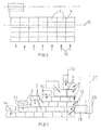
- Fig. 1 is a schematic plan view of a first embodiment of the apparatus according to the invention.
- Fig. 2 is a schematic plan view of a second embodiment of the apparatus according to the invention.
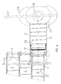
- Fig. 3 is a partial cross-sectional view of a conveyor alley of the apparatus according to the invention.
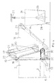
- Fig. 4 is a schematic side view of the discharge side of the conveyor alleys of the apparatus according to Fig. 1 .
- Fig. 5 is a larger-scale view of a part of the side view of Fig. 4 .
- Fig. 6 is a schematic plan view of the discharge side of the apparatus of Fig. 1 .
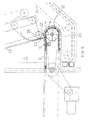
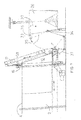
- Fig. 7 is a side view corresponding to Fig. 4 of the discharge side of a third embodiment of the apparatus according to the invention.
- Fig. 1 a schematic plan view is shown of an apparatus for separating and mixing feed for livestock, which apparatus comprises six units 1 arranged in side-by-side relationship for processing feed. A larger or a smaller number of units, even a single unit, may be used in other embodiments.
- Each unit 1 comprises a conveyor alley or conveyor passageway 2 for receiving one or more bales of feed 3, possibly with loose fodder between said bales.
- the feed placed on the various conveyor alleys 2 may consist of bales of maize and grass of different qualities, bales of stray and bales of alfalfa, for example.
- Fig. 3 is a partial cross-sectional view of a conveyor alley 2, which clearly shows that the conveyor alleys 2 are bounded by sideboards 4 on either side.
- Fig. 3 furthermore shows that each conveyor alley 2 comprises conveying means, in the form of endless conveyor chains 5 in the illustrated embodiment, which extend between return sprockets 6 and 7 as shown in Figs. 3 and 4 .
- conveying means other than conveyor chains may be used, for example a block slide, hydraulic conveying means and the like.
- the upper part of the conveyor chains 5 is guided in troughs 8, which extend in the longitudinal direction of a bottom 9 of the associated conveyor alley 2.
- Carriers 10 extending transversely to the conveying direction are provided on the conveyor chains 5.
- the carriers 10 are supported on the bottom 9 and are capable of moving the bales that have been placed on the conveyor alley 2 at an inlet side 11 towards a discharge side 12 when the conveyor chains 5 are driven.
- the drive unit for the conveyor chains 5 is schematically indicated at 13 in Fig. 4 .
- Fig. 1 the direction in which the bales 3 are fed to the conveyor alleys 2 is indicated by arrows 14.
- said feeding direction extends transversely to the conveying direction of the bales on the conveyor alleys 2.
- the sideboards 4 are strengthened at the inlet side 11, functioning as bumper boards, so that the bales can be pushed against said bumper boards by means of a tractor so as to ensure that the bales are correctly placed on the bottom 9, with their longitudinal axis extending in the conveying direction of the conveyor. This prevents the bales 3 getting wedged between the sideboards 4.
- bales are placed on the bottom 9 with their longitudinal axis in line with the conveying direction of the conveyor alleys 2 in Fig. 1 , it is also possible, if desired, to place the bales 3 on the bottom 9 with their longitudinal axis extending transversely to the conveying direction of the conveyor alleys 2.
- FIG. 2 such an embodiment is shown in schematic plan view, in which the feeding direction likewise extends in line with the conveying direction of the conveyor chains 5, as indicated by an arrow 15.
- Fig. 4 is a schematic side view of the discharge side of the conveyor alleys of the apparatus according to Fig. 1 , showing a frame 16 disposed at the discharge side 12 of the conveyor alley 2.
- Said frame 16 extends over the discharge sides 12 of all the side-by-side conveyor alleys 2 and carries a cutting unit 17, which forms part of a discharge unit 18 in this embodiment.
- the discharge unit 18 is guided on a transverse guide 19 at the upper side of the frame 16 and a transverse guide 20 at the bottom side of the frame 16.
- the cutting unit 17 is movable transversely to the conveyor alleys 2, with a drive unit (not shown) moving the cutting unit 17 to operating positions in which the cutting unit 17 and the discharge unit 18 are in line with a conveyor alley 2, as is shown in plan view in Fig. 6 .
- the cutting unit 17 comprises a frame 20, along which the cutting unit 17 can be moved up and down by a drive unit 21 (schematically indicated).
- the frame 20 is disposed at an angle with respect to the vertical, so that the cutting unit 17 will follow an inclined cutting path upon moving downwards, with a cutting knife 22, which is shown in more detail in Fig. 5 , forming an inclined cut surface 23.
- the cutting path does not have to be a straight line, but that it may also follow a curved line, so that the cut surface will not be flat but curved.
- a cutting knife comprising two reciprocable blades may be used.
- the cutting unit 17 may also be provided with cutting means other than the cutting knife 22.
- the term cutting unit as used in the description and the claims is to be understood to mean any unit by means of which a slice of feed can be separated from the end of the bale that faces towards the discharge side.
- the cutting unit 17 cuts a slice of feed from the end facing towards the discharge side of the bale 3 that is present at the discharge side, forming the inclined cut surface, which may or may not be curved, so that the end side of the remaining part of the bale 3 is rearwardly inclined with respect to the vertical. Moreover, said remaining part of the bale 3 is shorter at the upper side than at the bottom side in this case. This achieves that no chunks of feed will come off the remaining part of the bale and fall into the discharge unit 18, and that the remaining part of the bale 3 will remain in a stable position on the bottom 9 of the conveyor alley 2, also if the mayor part has already been cut from the bale.
- the cutting unit 17 can precisely cut a desired amount of feed from the bale 3 present at the discharge side 12, which amount can be measured by weighing means (not shown). Once the desired amount of feed has been cut from the bale 3, the cutting process is stopped.
- the thickness of the slice of feed that is cut from the bale 3 by the cutting unit 17 can be selected by varying the distance over which the bale is moved to the discharge side by the conveyor chains 5. According to one embodiment (not shown) of the apparatus described herein, the thickness of the slice to be separated can also be determined in that the cutting unit 17 is movable in the longitudinal direction of the conveyor alleys 2.
- the discharge unit 18 comprises a discharge conveyor belt 24 that can be driven by a drive unit 25 (schematically indicated).
- the discharge conveyor belt 24 discharges the feed that has been cut from the bale 3 to a mixing bin 26, which is suspended from a rail 27 in this embodiment.
- the mixing bin 26 is provided with flaps 28 (schematically indicated) on either side, via which the feed mixture from the mixing bin 26 can be delivered to the livestock.
- a mixing element 29 Disposed inside the mixing bin 26 is a mixing element 29, for example in the form of a vertical mixing screw. It is also possible to fit the mixing bin with more than one vertical mixing screw.
- the mixing element 29 ensures that a correct homogeneous composition of the feed mixture is obtained, which mixture may consist of portions from various bales 3 from the various conveyor alleys 2 and any other feed components.
- the feed can be mixed to obtain a feed mixture.
- the mixing bin 26 is moved to the livestock shed via the rail 27. In the shed, the feed mixture is delivered to the livestock in a metered manner via the flaps 28.
- the mixing bin 26 is provided with a driving motor for moving the mixing bin along the rail 27, with the power supply to the driving motor possibly taking place via the rail 27 or by means of a battery. Furthermore it is possible for the mixing bin 26 to move the discharge unit 18 to the conveyor alleys 2 from which feed is to be received. The mixing bin 26 may to that end be coupled to the discharge unit 18 at the location of the conveyor alleys 2.
- the amount of feed can be determined by weighing means (not shown). Said weighing means can weigh the feed that falls into the discharge unit 18, for example. This has the advantage that the discharge unit 18 can receive feed components in a desired composition thereof before the mixing bin 26 is present. Alternatively, the weighing means can determine the amount of feed in the mixing bin 26. According to another possibility, the weighing means can weigh both the feed in the discharge unit 18 and the feed in the mixing bin 26. To that end weighing sensors may be provided in the supporting structure of the conveyor belt 24 and in the suspension of the mixing bin 26 from the rail 27. Since the cutting unit 17 cuts feed from a bale 3 according to the cut surface 23 as described above, the cutting process can be stopped at the exact moment that a desired amount of separated feed is obtained. The remaining part of the bale 3 remains stable, so that no chunks of feed will undesirably fall into the discharge unit 18.
- the cutting unit 17 moves upwards to the position of rest that is shown in Fig. 4 . Subsequently the conveyor chains 5 are moved some distance from the discharge side 12 towards the inlet side, so that the conveyor alley 2 will be entirely clear at the discharge side. The cutting unit 17 and the discharge unit 18 can then be moved to a next conveyor alley 2 for a different type of feed.
- the apparatus as described herein may comprise a suitable control unit by means of which the feeding process can be controlled fully automatically.
- the discharge conveyor belt 24 comprises a portion 30 that extends under the discharge side 12 of the conveyor alleys 2.
- the discharge unit 18 comprises sideboards 31.
- the spacing between the sideboards 31 and the width of the discharge conveyor belts 24 are at least equal to the spacing between the boards 4 that bound the widest conveyor alley 2.
- a transverse slot 32 is provided in the bottom 9 at the location of the return sprocket 7, into which slot the cutting knife 22 of the cutting unit 17 may extend, which ensures that the cutting unit 17 will correctly separate the slice of feed from the bale 3 that is present at the discharge side 12.
- One of the boards 4 that bound each conveyor alley 2 at the discharge side 12 may be movable in a direction transverse to the conveying direction, for example be pivotable about a vertical axis, in which case a driving element, e.g. a cylinder-piston assembly, may push the movable board 4 against the bale that is present at the discharge side 12. This causes the bale to be clamped between the two boards 4, so that the bale 3 is held while being cut by the cutting unit 17. This helps to obtain a correct cutting result and prevents the bale from being pulled apart and chunks of feed unintentionally falling into the discharge unit 18.
- a driving element e.g. a cylinder-piston assembly
- Fig. 7 shows an alternative embodiment of the apparatus according to the invention, in which the cutting unit 17 does not comprise a discharge unit 18.
- the mixing bin 26 comprises a loading bucket 33 (schematically indicated).
- Said loading bucket 33 is pivotally connected to the mixing bin 26 at 34 and comprises three pivotally interconnected parts 35, 36 and 37, which parts can be moved from the position that is illustrated in a broken line in figure 7 to the loading position that is illustrated in a full line for loading the mixing bin 26.
- the loading bucket part 37 is positioned under the discharge side 12 of the conveyor alley 2 opposite which the mixing bin 26 is positioned.
- the loading bucket parts 34-36 are provided with side walls that can slide over each other.
- a non-movable discharge unit may be used with the cutting unit 17 that is shown in Fig. 7 , which discharge unit comprises a first conveyor belt extending transversely to the conveyor alleys 2, partially under the discharge sides 12 thereof, which conveyor belt supplies the separated feed to a second conveyor belt. Said second conveyor belt slopes upwards and is capable of depositing the feed in the mixing bin 26.
- the weighing means comprise sensors accommodated in the supporting structure of the conveyor belt(s).
- the cutting unit 17 is provided with discharge means for discharging the separated slice of feed from the cutting unit.
- discharge means for discharging the separated slice of feed from the cutting unit.
- a roller 38 is shown as an example of said discharge means, which roller is rotatably mounted - drivably, if desired - in the cutting unit 17.
- Applicant's Dutch patent application No. 1028732 for a further explanation of possible embodiments of such discharge means reference is made to Applicant's Dutch patent application No. 1028732 .
- the conveyor alleys 2 in an inclined position, at least the part thereof that is located at the discharge side, so that the discharge side 12 will be positioned higher than the inlet side 11.
- the cutting unit 17 can follow a cutting path substantially perpendicular to the bottom of the conveyor alley, for example, so that the end side of the remaining part of the bale 3 that faces towards the discharge side 12 is rearwardly inclined with respect to the vertical.
- material of the bale is prevented from unintentionally falling into the discharge unit 18 or the mixing bin 26, and the remaining part of the bale will remain in a stable position on the bottom of the conveyor alley 2.
- the cutting path may be curved, and the cutting path may also extend at an angle to the bottom of the conveyor.
Landscapes
- Life Sciences & Earth Sciences (AREA)
- Environmental Sciences (AREA)
- Birds (AREA)
- Animal Husbandry (AREA)
- Biodiversity & Conservation Biology (AREA)
- Apparatuses For Bulk Treatment Of Fruits And Vegetables And Apparatuses For Preparing Feeds (AREA)
- Feeding And Watering For Cattle Raising And Animal Husbandry (AREA)
- Feed For Specific Animals (AREA)
- Fodder In General (AREA)
Applications Claiming Priority (2)
| Application Number | Priority Date | Filing Date | Title |
|---|---|---|---|
| NL1029075A NL1029075C2 (nl) | 2005-05-19 | 2005-05-19 | Inrichting en werkwijze voor het losmaken en mengen van voer voor vee. |
| EP06113032A EP1723846B1 (de) | 2005-05-19 | 2006-04-25 | Anlage und Verfahren zum Trennen und Mischen von Viehfutter |
Related Parent Applications (2)
| Application Number | Title | Priority Date | Filing Date |
|---|---|---|---|
| EP06113032A Division EP1723846B1 (de) | 2005-05-19 | 2006-04-25 | Anlage und Verfahren zum Trennen und Mischen von Viehfutter |
| EP06113032.4 Division | 2006-04-25 |
Publications (5)
| Publication Number | Publication Date |
|---|---|
| EP1935239A2 true EP1935239A2 (de) | 2008-06-25 |
| EP1935239A3 EP1935239A3 (de) | 2009-02-25 |
| EP1935239B1 EP1935239B1 (de) | 2010-10-06 |
| EP1935239B2 EP1935239B2 (de) | 2018-09-26 |
| EP1935239B8 EP1935239B8 (de) | 2018-12-19 |
Family
ID=35295352
Family Applications (6)
| Application Number | Title | Priority Date | Filing Date |
|---|---|---|---|
| EP08154449A Expired - Lifetime EP1935238B1 (de) | 2005-05-19 | 2006-04-25 | Vorrichtung und Verfahren zum Trennen und Mischen von Viehfutter |
| EP06113032A Expired - Lifetime EP1723846B1 (de) | 2005-05-19 | 2006-04-25 | Anlage und Verfahren zum Trennen und Mischen von Viehfutter |
| EP08154431A Withdrawn EP1935237A3 (de) | 2005-05-19 | 2006-04-25 | Anlage und Verfahren zum Trennen und Mischen von Viehfutter |
| EP08154450.4A Expired - Lifetime EP1935239B8 (de) | 2005-05-19 | 2006-04-25 | Vorrichtung und Verfahren zum Trennen und Mischen von Viehfutter |
| EP08154447A Expired - Lifetime EP1938682B1 (de) | 2005-05-19 | 2006-04-25 | Anlage und Verfahren zum Trennen und Mischen von Viehfutter |
| EP08154451A Withdrawn EP1935240A3 (de) | 2005-05-19 | 2006-04-25 | Vorrichtung und Verfahren zum Trennen und Mischen von Viehfutter |
Family Applications Before (3)
| Application Number | Title | Priority Date | Filing Date |
|---|---|---|---|
| EP08154449A Expired - Lifetime EP1935238B1 (de) | 2005-05-19 | 2006-04-25 | Vorrichtung und Verfahren zum Trennen und Mischen von Viehfutter |
| EP06113032A Expired - Lifetime EP1723846B1 (de) | 2005-05-19 | 2006-04-25 | Anlage und Verfahren zum Trennen und Mischen von Viehfutter |
| EP08154431A Withdrawn EP1935237A3 (de) | 2005-05-19 | 2006-04-25 | Anlage und Verfahren zum Trennen und Mischen von Viehfutter |
Family Applications After (2)
| Application Number | Title | Priority Date | Filing Date |
|---|---|---|---|
| EP08154447A Expired - Lifetime EP1938682B1 (de) | 2005-05-19 | 2006-04-25 | Anlage und Verfahren zum Trennen und Mischen von Viehfutter |
| EP08154451A Withdrawn EP1935240A3 (de) | 2005-05-19 | 2006-04-25 | Vorrichtung und Verfahren zum Trennen und Mischen von Viehfutter |
Country Status (5)
| Country | Link |
|---|---|
| EP (6) | EP1935238B1 (de) |
| AT (1) | ATE392809T1 (de) |
| DE (4) | DE602006017572D1 (de) |
| DK (4) | DK1938682T3 (de) |
| NL (1) | NL1029075C2 (de) |
Families Citing this family (10)
| Publication number | Priority date | Publication date | Assignee | Title |
|---|---|---|---|---|
| EP2042033A3 (de) * | 2007-09-28 | 2009-06-17 | Skiold Mullerup A/S | Futterzuführmagazin wobei Futter auf einem Transportband in eine Futterschneideabteilung befördert wird |
| WO2009045158A1 (en) * | 2007-10-02 | 2009-04-09 | Delaval Holding Ab | Method and system for preparing feed |
| NL2001757C2 (nl) | 2008-07-04 | 2010-01-05 | Trioliet Mullos | Inrichting voor het losmaken en mengen van voer voor vee. |
| DE102010033886B4 (de) | 2010-08-10 | 2014-12-31 | B. Strautmann & Söhne GmbH u. Co. KG | Verfahren und Vorrichtung zur Ermittlung der Homogenität einer Futtermischung |
| DE102010033887B4 (de) | 2010-08-10 | 2015-02-19 | B. Strautmann & Söhne GmbH u. Co. KG | Verfahren und Vorrichtung zur optimierten Fütterung von Milchvieh |
| DE102010033888A1 (de) | 2010-08-10 | 2012-02-16 | B. Strautmann & Söhne GmbH u. Co. KG | Verfahren und Vorrichtung zur Optimierung der Futterentnahme aus Flachsilos |
| EP3125681B1 (de) * | 2014-04-03 | 2017-11-08 | DeLaval Holding AB | Tierfutterhandhabungsanordnung und verfahren zur steuerung davon |
| ES2528416B1 (es) | 2014-07-01 | 2015-07-08 | Grupo Tatoma, S.L. | Planta estática de preparación de mezclas alimentarias para ganado rumiante |
| CN107593630B (zh) * | 2017-10-31 | 2022-09-23 | 广西民族大学 | 一种桑蚕喂食装置 |
| NL2021282B1 (en) * | 2018-07-11 | 2020-01-20 | Africhtings En Handelsstal De Visser | Forage processor |
Citations (2)
| Publication number | Priority date | Publication date | Assignee | Title |
|---|---|---|---|---|
| NL1026841C2 (nl) | 2004-08-13 | 2006-02-14 | Trioliet Mullos | Inrichting voor het losmaken en mengen van voer voor vee. |
| NL1028732C2 (nl) | 2005-04-11 | 2006-10-12 | Trioliet Mullos | Inrichting voor het uithalen en verwerken van ruwvoer voor vee. |
Family Cites Families (15)
| Publication number | Priority date | Publication date | Assignee | Title |
|---|---|---|---|---|
| DE1026841B (de) | 1953-12-02 | 1958-03-27 | Licentia Gmbh | Stabfoermiger unterteilter Leiter fuer hohen Beanspruchungen ausgesetzte Wechselstrommaschinen |
| DE1028732B (de) | 1953-12-24 | 1958-04-24 | Dcm Daniels Cotton Maschinenfa | Flache Kulierwirkmaschine |
| US3830438A (en) * | 1972-01-20 | 1974-08-20 | Hesston Corp | Machine for feeding materials from a stack |
| DE2502422A1 (de) * | 1975-01-22 | 1976-07-29 | Hubert Wellermann | Vorrichtung zur herstellung von trennschnitten in gaerfutter |
| DE2810676A1 (de) † | 1978-03-11 | 1979-09-20 | Krone Bernhard Gmbh Maschf | Dosiervorrichtung fuer landwirtschaftliche erntegueter |
| US4258886A (en) * | 1978-06-22 | 1981-03-31 | Ezra C. Lundahl, Inc. | Variable stack feeder with hydraulic control |
| DE4027527A1 (de) * | 1990-08-31 | 1992-03-05 | Strautmann & Soehne | Geraet zum aufnehmen, zerschneiden und verteilen von stroh- und futterballen |
| US5333799A (en) * | 1993-02-09 | 1994-08-02 | A & P Mfg., Inc. | Bale cutting machine |
| DE9303751U1 (de) * | 1993-03-13 | 1994-07-21 | Aßfalg, Alois, 89597 Unterwachingen | Ladewagen zum Abtragen von Erntegut wie Silage, Halmgut o.dgl. aus einem Futterstock |
| DE4319507A1 (de) † | 1993-06-12 | 1994-12-15 | Strautmann & Soehne | Gerät zum Aufnehmen, Zerschneiden und Verteilen von zylindrischen oder quaderförmigen Futterballen |
| FR2759538B1 (fr) † | 1997-02-20 | 1999-05-07 | Lucas Sa G | Dispositif demeleur-dechiqueteur de produits du genre fourrage ou paille, disposes en vrac ou en balles dans la benne d'une machine distributrice |
| NL1006170C2 (nl) * | 1997-05-30 | 1998-12-01 | Trioliet Mullos | Werkwijze en inrichting voor het mengen van voer. |
| NL1011109C2 (nl) * | 1999-01-22 | 2000-07-25 | Trioliet Mullos | Verplaatsbare inrichting voor afgeven van voer en werkwijze voor het afgeven van voer. |
| DE19938090A1 (de) * | 1999-09-10 | 2001-02-15 | Bernd Zielke | Ballenauflöser/Ballenfräse für Rund- und Quaderballen |
| NL1022678C2 (nl) * | 2003-02-14 | 2004-08-17 | Trioliet Mullos | Werkwijze en inrichting voor het uithalen van een hoeveelheid voer uit een voedervoorraad. |
-
2005
- 2005-05-19 NL NL1029075A patent/NL1029075C2/nl not_active IP Right Cessation
-
2006
- 2006-04-25 EP EP08154449A patent/EP1935238B1/de not_active Expired - Lifetime
- 2006-04-25 DK DK08154447.0T patent/DK1938682T3/da active
- 2006-04-25 DK DK08154450.4T patent/DK1935239T4/en active
- 2006-04-25 EP EP06113032A patent/EP1723846B1/de not_active Expired - Lifetime
- 2006-04-25 EP EP08154431A patent/EP1935237A3/de not_active Withdrawn
- 2006-04-25 EP EP08154450.4A patent/EP1935239B8/de not_active Expired - Lifetime
- 2006-04-25 DE DE602006017572T patent/DE602006017572D1/de not_active Expired - Lifetime
- 2006-04-25 DE DE602006016312T patent/DE602006016312D1/de not_active Expired - Lifetime
- 2006-04-25 DE DE602006017412T patent/DE602006017412D1/de not_active Expired - Lifetime
- 2006-04-25 DK DK08154449.6T patent/DK1935238T3/da active
- 2006-04-25 DK DK06113032T patent/DK1723846T3/da active
- 2006-04-25 EP EP08154447A patent/EP1938682B1/de not_active Expired - Lifetime
- 2006-04-25 DE DE602006000974T patent/DE602006000974T2/de not_active Expired - Lifetime
- 2006-04-25 EP EP08154451A patent/EP1935240A3/de not_active Withdrawn
- 2006-04-25 AT AT06113032T patent/ATE392809T1/de not_active IP Right Cessation
Patent Citations (2)
| Publication number | Priority date | Publication date | Assignee | Title |
|---|---|---|---|---|
| NL1026841C2 (nl) | 2004-08-13 | 2006-02-14 | Trioliet Mullos | Inrichting voor het losmaken en mengen van voer voor vee. |
| NL1028732C2 (nl) | 2005-04-11 | 2006-10-12 | Trioliet Mullos | Inrichting voor het uithalen en verwerken van ruwvoer voor vee. |
Also Published As
| Publication number | Publication date |
|---|---|
| DK1723846T3 (da) | 2008-08-04 |
| EP1723846B1 (de) | 2008-04-23 |
| EP1723846A1 (de) | 2006-11-22 |
| EP1935240A3 (de) | 2009-02-25 |
| EP1938682A3 (de) | 2009-02-25 |
| EP1935239B8 (de) | 2018-12-19 |
| EP1935237A2 (de) | 2008-06-25 |
| EP1935238A3 (de) | 2009-02-25 |
| ATE392809T1 (de) | 2008-05-15 |
| DK1935239T3 (da) | 2011-01-24 |
| DK1938682T3 (da) | 2010-12-13 |
| EP1938682A2 (de) | 2008-07-02 |
| EP1935238A2 (de) | 2008-06-25 |
| EP1935240A2 (de) | 2008-06-25 |
| NL1029075C2 (nl) | 2006-11-21 |
| DK1935239T4 (en) | 2019-01-07 |
| DE602006017412D1 (de) | 2010-11-18 |
| DK1935238T3 (da) | 2011-01-31 |
| EP1935237A3 (de) | 2009-02-25 |
| EP1935239A3 (de) | 2009-02-25 |
| DE602006017572D1 (de) | 2010-11-25 |
| DE602006000974D1 (de) | 2008-06-05 |
| EP1935239B2 (de) | 2018-09-26 |
| DE602006000974T2 (de) | 2009-05-28 |
| EP1938682B1 (de) | 2010-08-18 |
| DE602006016312D1 (de) | 2010-09-30 |
| EP1935239B1 (de) | 2010-10-06 |
| EP1935238B1 (de) | 2010-10-13 |
Similar Documents
| Publication | Publication Date | Title |
|---|---|---|
| US5025992A (en) | Hay feeding apparatus | |
| EP1935239B1 (de) | Vorrichtung und Verfahren zum Trennen und Mischen von Viehfutter | |
| EP2386201B1 (de) | Vorichtung zum Trennen und Mischen von Futter für Nutztiere | |
| US10674675B2 (en) | Processing of blocks or bales of feed | |
| US12122615B2 (en) | Insert feed unit as well as a method for its operation | |
| CA2499678C (en) | Round baler leaf reclamation device | |
| US4538949A (en) | Conveyor for conveying silage or the like material | |
| EP1625787B1 (de) | Anlage zum Trennen und Mischen von Viehfutter | |
| DK158062B (da) | Optagelses- og fordelingsvogn til ensilage, halm- og lignende materiale | |
| CA2088571C (en) | Apparatus for top and tailing vegetables | |
| US4018391A (en) | Controlled hay bale metering and feeding device | |
| CA1039685A (en) | Stack feeding apparatus | |
| EP2061306B1 (de) | Vorrichtung zur dosierung von futter für vieh | |
| US3786783A (en) | Feed conveying and dispensing apparatus | |
| CA2568004A1 (en) | In-feed distributing unit | |
| JP3035503U (ja) | 家畜用飼料の搬送装置 | |
| AU724286B2 (en) | A bale dispenser | |
| WO2025122020A1 (en) | Autonomous feed preparation vehicle and feed preparation system with the use of the autonomous feed preparation vehicle | |
| SU1219022A1 (ru) | Установка дл раздачи кормов в животноводческих помещени х | |
| JPH04110356U (ja) | 氷垂直搬送装置の放出部構造 | |
| GB2111375A (en) | Apparatus for unloading silage from a bunker silo | |
| DE2646957A1 (de) | Vorrichtung zum abgeben von rohem viehfutter | |
| NL8900154A (nl) | Een constructie voor het automatisch voeren van koeien. | |
| CS235862B1 (cs) | Příčný dopravník, zejména pro zemědělské stroje | |
| KR20070090865A (ko) | 볏짚 커팅장치 |
Legal Events
| Date | Code | Title | Description |
|---|---|---|---|
| PUAI | Public reference made under article 153(3) epc to a published international application that has entered the european phase |
Free format text: ORIGINAL CODE: 0009012 |
|
| AC | Divisional application: reference to earlier application |
Ref document number: 1723846 Country of ref document: EP Kind code of ref document: P |
|
| AK | Designated contracting states |
Kind code of ref document: A2 Designated state(s): AT BE BG CH CY CZ DE DK EE ES FI FR GB GR HU IE IS IT LI LT LU LV MC NL PL PT RO SE SI SK TR |
|
| PUAL | Search report despatched |
Free format text: ORIGINAL CODE: 0009013 |
|
| AK | Designated contracting states |
Kind code of ref document: A3 Designated state(s): AT BE BG CH CY CZ DE DK EE ES FI FR GB GR HU IE IS IT LI LT LU LV MC NL PL PT RO SE SI SK TR |
|
| RIC1 | Information provided on ipc code assigned before grant |
Ipc: A01K 5/00 20060101AFI20080522BHEP Ipc: A01F 29/00 20060101ALI20090121BHEP |
|
| 17P | Request for examination filed |
Effective date: 20090810 |
|
| 17Q | First examination report despatched |
Effective date: 20090910 |
|
| AKX | Designation fees paid |
Designated state(s): DE DK NL |
|
| GRAP | Despatch of communication of intention to grant a patent |
Free format text: ORIGINAL CODE: EPIDOSNIGR1 |
|
| GRAS | Grant fee paid |
Free format text: ORIGINAL CODE: EPIDOSNIGR3 |
|
| GRAA | (expected) grant |
Free format text: ORIGINAL CODE: 0009210 |
|
| AC | Divisional application: reference to earlier application |
Ref document number: 1723846 Country of ref document: EP Kind code of ref document: P |
|
| AK | Designated contracting states |
Kind code of ref document: B1 Designated state(s): DE DK NL |
|
| REG | Reference to a national code |
Ref country code: NL Ref legal event code: T3 |
|
| REF | Corresponds to: |
Ref document number: 602006017412 Country of ref document: DE Date of ref document: 20101118 Kind code of ref document: P |
|
| REG | Reference to a national code |
Ref country code: DK Ref legal event code: T3 |
|
| PLBI | Opposition filed |
Free format text: ORIGINAL CODE: 0009260 |
|
| 26 | Opposition filed |
Opponent name: GEA FARM TECHNOLOGIES GMBH Effective date: 20110706 |
|
| PLAX | Notice of opposition and request to file observation + time limit sent |
Free format text: ORIGINAL CODE: EPIDOSNOBS2 |
|
| REG | Reference to a national code |
Ref country code: DE Ref legal event code: R026 Ref document number: 602006017412 Country of ref document: DE Effective date: 20110706 |
|
| PLBB | Reply of patent proprietor to notice(s) of opposition received |
Free format text: ORIGINAL CODE: EPIDOSNOBS3 |
|
| PLCK | Communication despatched that opposition was rejected |
Free format text: ORIGINAL CODE: EPIDOSNREJ1 |
|
| APAH | Appeal reference modified |
Free format text: ORIGINAL CODE: EPIDOSCREFNO |
|
| APBM | Appeal reference recorded |
Free format text: ORIGINAL CODE: EPIDOSNREFNO |
|
| APBP | Date of receipt of notice of appeal recorded |
Free format text: ORIGINAL CODE: EPIDOSNNOA2O |
|
| APBQ | Date of receipt of statement of grounds of appeal recorded |
Free format text: ORIGINAL CODE: EPIDOSNNOA3O |
|
| PLAB | Opposition data, opponent's data or that of the opponent's representative modified |
Free format text: ORIGINAL CODE: 0009299OPPO |
|
| R26 | Opposition filed (corrected) |
Opponent name: GEA FARM TECHNOLOGIES GMBH Effective date: 20110706 |
|
| APBU | Appeal procedure closed |
Free format text: ORIGINAL CODE: EPIDOSNNOA9O |
|
| PUAH | Patent maintained in amended form |
Free format text: ORIGINAL CODE: 0009272 |
|
| STAA | Information on the status of an ep patent application or granted ep patent |
Free format text: STATUS: PATENT MAINTAINED AS AMENDED |
|
| 27A | Patent maintained in amended form |
Effective date: 20180926 |
|
| AK | Designated contracting states |
Kind code of ref document: B2 Designated state(s): DE DK NL |
|
| REG | Reference to a national code |
Ref country code: DE Ref legal event code: R102 Ref document number: 602006017412 Country of ref document: DE |
|
| REG | Reference to a national code |
Ref country code: DK Ref legal event code: T4 Effective date: 20190104 |
|
| REG | Reference to a national code |
Ref country code: NL Ref legal event code: FP |
|
| REG | Reference to a national code |
Ref country code: NL Ref legal event code: PD Owner name: TRIOLIET HOLDING B.V; NL Free format text: DETAILS ASSIGNMENT: CHANGE OF OWNER(S), ASSIGNMENT; FORMER OWNER NAME: TRIOLIET MULLOS B.V. Effective date: 20190215 |
|
| PGFP | Annual fee paid to national office [announced via postgrant information from national office to epo] |
Ref country code: DE Payment date: 20200429 Year of fee payment: 15 Ref country code: NL Payment date: 20200429 Year of fee payment: 15 Ref country code: DK Payment date: 20200430 Year of fee payment: 15 |
|
| REG | Reference to a national code |
Ref country code: DE Ref legal event code: R119 Ref document number: 602006017412 Country of ref document: DE |
|
| REG | Reference to a national code |
Ref country code: DK Ref legal event code: EBP Effective date: 20210430 |
|
| REG | Reference to a national code |
Ref country code: NL Ref legal event code: MM Effective date: 20210501 |
|
| PG25 | Lapsed in a contracting state [announced via postgrant information from national office to epo] |
Ref country code: DE Free format text: LAPSE BECAUSE OF NON-PAYMENT OF DUE FEES Effective date: 20211103 |
|
| PG25 | Lapsed in a contracting state [announced via postgrant information from national office to epo] |
Ref country code: NL Free format text: LAPSE BECAUSE OF NON-PAYMENT OF DUE FEES Effective date: 20210501 |
|
| PG25 | Lapsed in a contracting state [announced via postgrant information from national office to epo] |
Ref country code: DK Free format text: LAPSE BECAUSE OF NON-PAYMENT OF DUE FEES Effective date: 20210430 |