EP1932741A2 - Hybrid-Antrieb mit Doppelkupplung - Google Patents
Hybrid-Antrieb mit Doppelkupplung Download PDFInfo
- Publication number
- EP1932741A2 EP1932741A2 EP07021058A EP07021058A EP1932741A2 EP 1932741 A2 EP1932741 A2 EP 1932741A2 EP 07021058 A EP07021058 A EP 07021058A EP 07021058 A EP07021058 A EP 07021058A EP 1932741 A2 EP1932741 A2 EP 1932741A2
- Authority
- EP
- European Patent Office
- Prior art keywords
- clutch
- double clutch
- electric motor
- output shaft
- closed
- Prior art date
- Legal status (The legal status is an assumption and is not a legal conclusion. Google has not performed a legal analysis and makes no representation as to the accuracy of the status listed.)
- Withdrawn
Links
Images


Classifications
-
- B—PERFORMING OPERATIONS; TRANSPORTING
- B60—VEHICLES IN GENERAL
- B60W—CONJOINT CONTROL OF VEHICLE SUB-UNITS OF DIFFERENT TYPE OR DIFFERENT FUNCTION; CONTROL SYSTEMS SPECIALLY ADAPTED FOR HYBRID VEHICLES; ROAD VEHICLE DRIVE CONTROL SYSTEMS FOR PURPOSES NOT RELATED TO THE CONTROL OF A PARTICULAR SUB-UNIT
- B60W20/00—Control systems specially adapted for hybrid vehicles
- B60W20/10—Controlling the power contribution of each of the prime movers to meet required power demand
-
- B—PERFORMING OPERATIONS; TRANSPORTING
- B60—VEHICLES IN GENERAL
- B60K—ARRANGEMENT OR MOUNTING OF PROPULSION UNITS OR OF TRANSMISSIONS IN VEHICLES; ARRANGEMENT OR MOUNTING OF PLURAL DIVERSE PRIME-MOVERS IN VEHICLES; AUXILIARY DRIVES FOR VEHICLES; INSTRUMENTATION OR DASHBOARDS FOR VEHICLES; ARRANGEMENTS IN CONNECTION WITH COOLING, AIR INTAKE, GAS EXHAUST OR FUEL SUPPLY OF PROPULSION UNITS IN VEHICLES
- B60K6/00—Arrangement or mounting of plural diverse prime-movers for mutual or common propulsion, e.g. hybrid propulsion systems comprising electric motors and internal combustion engines
- B60K6/20—Arrangement or mounting of plural diverse prime-movers for mutual or common propulsion, e.g. hybrid propulsion systems comprising electric motors and internal combustion engines the prime-movers consisting of electric motors and internal combustion engines, e.g. HEVs
- B60K6/50—Architecture of the driveline characterised by arrangement or kind of transmission units
-
- B—PERFORMING OPERATIONS; TRANSPORTING
- B60—VEHICLES IN GENERAL
- B60K—ARRANGEMENT OR MOUNTING OF PROPULSION UNITS OR OF TRANSMISSIONS IN VEHICLES; ARRANGEMENT OR MOUNTING OF PLURAL DIVERSE PRIME-MOVERS IN VEHICLES; AUXILIARY DRIVES FOR VEHICLES; INSTRUMENTATION OR DASHBOARDS FOR VEHICLES; ARRANGEMENTS IN CONNECTION WITH COOLING, AIR INTAKE, GAS EXHAUST OR FUEL SUPPLY OF PROPULSION UNITS IN VEHICLES
- B60K6/00—Arrangement or mounting of plural diverse prime-movers for mutual or common propulsion, e.g. hybrid propulsion systems comprising electric motors and internal combustion engines
- B60K6/20—Arrangement or mounting of plural diverse prime-movers for mutual or common propulsion, e.g. hybrid propulsion systems comprising electric motors and internal combustion engines the prime-movers consisting of electric motors and internal combustion engines, e.g. HEVs
- B60K6/22—Arrangement or mounting of plural diverse prime-movers for mutual or common propulsion, e.g. hybrid propulsion systems comprising electric motors and internal combustion engines the prime-movers consisting of electric motors and internal combustion engines, e.g. HEVs characterised by apparatus, components or means specially adapted for HEVs
- B60K6/38—Arrangement or mounting of plural diverse prime-movers for mutual or common propulsion, e.g. hybrid propulsion systems comprising electric motors and internal combustion engines the prime-movers consisting of electric motors and internal combustion engines, e.g. HEVs characterised by apparatus, components or means specially adapted for HEVs characterised by the driveline clutches
- B60K6/387—Actuated clutches, i.e. clutches engaged or disengaged by electric, hydraulic or mechanical actuating means
-
- B—PERFORMING OPERATIONS; TRANSPORTING
- B60—VEHICLES IN GENERAL
- B60K—ARRANGEMENT OR MOUNTING OF PROPULSION UNITS OR OF TRANSMISSIONS IN VEHICLES; ARRANGEMENT OR MOUNTING OF PLURAL DIVERSE PRIME-MOVERS IN VEHICLES; AUXILIARY DRIVES FOR VEHICLES; INSTRUMENTATION OR DASHBOARDS FOR VEHICLES; ARRANGEMENTS IN CONNECTION WITH COOLING, AIR INTAKE, GAS EXHAUST OR FUEL SUPPLY OF PROPULSION UNITS IN VEHICLES
- B60K17/00—Arrangement or mounting of transmissions in vehicles
-
- B—PERFORMING OPERATIONS; TRANSPORTING
- B60—VEHICLES IN GENERAL
- B60K—ARRANGEMENT OR MOUNTING OF PROPULSION UNITS OR OF TRANSMISSIONS IN VEHICLES; ARRANGEMENT OR MOUNTING OF PLURAL DIVERSE PRIME-MOVERS IN VEHICLES; AUXILIARY DRIVES FOR VEHICLES; INSTRUMENTATION OR DASHBOARDS FOR VEHICLES; ARRANGEMENTS IN CONNECTION WITH COOLING, AIR INTAKE, GAS EXHAUST OR FUEL SUPPLY OF PROPULSION UNITS IN VEHICLES
- B60K23/00—Arrangement or mounting of control devices for vehicle transmissions, or parts thereof, not otherwise provided for
-
- B—PERFORMING OPERATIONS; TRANSPORTING
- B60—VEHICLES IN GENERAL
- B60K—ARRANGEMENT OR MOUNTING OF PROPULSION UNITS OR OF TRANSMISSIONS IN VEHICLES; ARRANGEMENT OR MOUNTING OF PLURAL DIVERSE PRIME-MOVERS IN VEHICLES; AUXILIARY DRIVES FOR VEHICLES; INSTRUMENTATION OR DASHBOARDS FOR VEHICLES; ARRANGEMENTS IN CONNECTION WITH COOLING, AIR INTAKE, GAS EXHAUST OR FUEL SUPPLY OF PROPULSION UNITS IN VEHICLES
- B60K6/00—Arrangement or mounting of plural diverse prime-movers for mutual or common propulsion, e.g. hybrid propulsion systems comprising electric motors and internal combustion engines
- B60K6/20—Arrangement or mounting of plural diverse prime-movers for mutual or common propulsion, e.g. hybrid propulsion systems comprising electric motors and internal combustion engines the prime-movers consisting of electric motors and internal combustion engines, e.g. HEVs
- B60K6/22—Arrangement or mounting of plural diverse prime-movers for mutual or common propulsion, e.g. hybrid propulsion systems comprising electric motors and internal combustion engines the prime-movers consisting of electric motors and internal combustion engines, e.g. HEVs characterised by apparatus, components or means specially adapted for HEVs
-
- B—PERFORMING OPERATIONS; TRANSPORTING
- B60—VEHICLES IN GENERAL
- B60K—ARRANGEMENT OR MOUNTING OF PROPULSION UNITS OR OF TRANSMISSIONS IN VEHICLES; ARRANGEMENT OR MOUNTING OF PLURAL DIVERSE PRIME-MOVERS IN VEHICLES; AUXILIARY DRIVES FOR VEHICLES; INSTRUMENTATION OR DASHBOARDS FOR VEHICLES; ARRANGEMENTS IN CONNECTION WITH COOLING, AIR INTAKE, GAS EXHAUST OR FUEL SUPPLY OF PROPULSION UNITS IN VEHICLES
- B60K6/00—Arrangement or mounting of plural diverse prime-movers for mutual or common propulsion, e.g. hybrid propulsion systems comprising electric motors and internal combustion engines
- B60K6/20—Arrangement or mounting of plural diverse prime-movers for mutual or common propulsion, e.g. hybrid propulsion systems comprising electric motors and internal combustion engines the prime-movers consisting of electric motors and internal combustion engines, e.g. HEVs
- B60K6/42—Arrangement or mounting of plural diverse prime-movers for mutual or common propulsion, e.g. hybrid propulsion systems comprising electric motors and internal combustion engines the prime-movers consisting of electric motors and internal combustion engines, e.g. HEVs characterised by the architecture of the hybrid electric vehicle
- B60K6/48—Parallel type
-
- B—PERFORMING OPERATIONS; TRANSPORTING
- B60—VEHICLES IN GENERAL
- B60K—ARRANGEMENT OR MOUNTING OF PROPULSION UNITS OR OF TRANSMISSIONS IN VEHICLES; ARRANGEMENT OR MOUNTING OF PLURAL DIVERSE PRIME-MOVERS IN VEHICLES; AUXILIARY DRIVES FOR VEHICLES; INSTRUMENTATION OR DASHBOARDS FOR VEHICLES; ARRANGEMENTS IN CONNECTION WITH COOLING, AIR INTAKE, GAS EXHAUST OR FUEL SUPPLY OF PROPULSION UNITS IN VEHICLES
- B60K6/00—Arrangement or mounting of plural diverse prime-movers for mutual or common propulsion, e.g. hybrid propulsion systems comprising electric motors and internal combustion engines
- B60K6/20—Arrangement or mounting of plural diverse prime-movers for mutual or common propulsion, e.g. hybrid propulsion systems comprising electric motors and internal combustion engines the prime-movers consisting of electric motors and internal combustion engines, e.g. HEVs
- B60K6/50—Architecture of the driveline characterised by arrangement or kind of transmission units
- B60K6/54—Transmission for changing ratio
- B60K6/547—Transmission for changing ratio the transmission being a stepped gearing
-
- B—PERFORMING OPERATIONS; TRANSPORTING
- B60—VEHICLES IN GENERAL
- B60W—CONJOINT CONTROL OF VEHICLE SUB-UNITS OF DIFFERENT TYPE OR DIFFERENT FUNCTION; CONTROL SYSTEMS SPECIALLY ADAPTED FOR HYBRID VEHICLES; ROAD VEHICLE DRIVE CONTROL SYSTEMS FOR PURPOSES NOT RELATED TO THE CONTROL OF A PARTICULAR SUB-UNIT
- B60W10/00—Conjoint control of vehicle sub-units of different type or different function
- B60W10/02—Conjoint control of vehicle sub-units of different type or different function including control of driveline clutches
-
- B—PERFORMING OPERATIONS; TRANSPORTING
- B60—VEHICLES IN GENERAL
- B60W—CONJOINT CONTROL OF VEHICLE SUB-UNITS OF DIFFERENT TYPE OR DIFFERENT FUNCTION; CONTROL SYSTEMS SPECIALLY ADAPTED FOR HYBRID VEHICLES; ROAD VEHICLE DRIVE CONTROL SYSTEMS FOR PURPOSES NOT RELATED TO THE CONTROL OF A PARTICULAR SUB-UNIT
- B60W10/00—Conjoint control of vehicle sub-units of different type or different function
- B60W10/04—Conjoint control of vehicle sub-units of different type or different function including control of propulsion units
- B60W10/06—Conjoint control of vehicle sub-units of different type or different function including control of propulsion units including control of combustion engines
-
- B—PERFORMING OPERATIONS; TRANSPORTING
- B60—VEHICLES IN GENERAL
- B60W—CONJOINT CONTROL OF VEHICLE SUB-UNITS OF DIFFERENT TYPE OR DIFFERENT FUNCTION; CONTROL SYSTEMS SPECIALLY ADAPTED FOR HYBRID VEHICLES; ROAD VEHICLE DRIVE CONTROL SYSTEMS FOR PURPOSES NOT RELATED TO THE CONTROL OF A PARTICULAR SUB-UNIT
- B60W10/00—Conjoint control of vehicle sub-units of different type or different function
- B60W10/04—Conjoint control of vehicle sub-units of different type or different function including control of propulsion units
- B60W10/08—Conjoint control of vehicle sub-units of different type or different function including control of propulsion units including control of electric propulsion units, e.g. motors or generators
-
- B—PERFORMING OPERATIONS; TRANSPORTING
- B60—VEHICLES IN GENERAL
- B60W—CONJOINT CONTROL OF VEHICLE SUB-UNITS OF DIFFERENT TYPE OR DIFFERENT FUNCTION; CONTROL SYSTEMS SPECIALLY ADAPTED FOR HYBRID VEHICLES; ROAD VEHICLE DRIVE CONTROL SYSTEMS FOR PURPOSES NOT RELATED TO THE CONTROL OF A PARTICULAR SUB-UNIT
- B60W10/00—Conjoint control of vehicle sub-units of different type or different function
- B60W10/10—Conjoint control of vehicle sub-units of different type or different function including control of change-speed gearings
-
- B—PERFORMING OPERATIONS; TRANSPORTING
- B60—VEHICLES IN GENERAL
- B60W—CONJOINT CONTROL OF VEHICLE SUB-UNITS OF DIFFERENT TYPE OR DIFFERENT FUNCTION; CONTROL SYSTEMS SPECIALLY ADAPTED FOR HYBRID VEHICLES; ROAD VEHICLE DRIVE CONTROL SYSTEMS FOR PURPOSES NOT RELATED TO THE CONTROL OF A PARTICULAR SUB-UNIT
- B60W10/00—Conjoint control of vehicle sub-units of different type or different function
- B60W10/10—Conjoint control of vehicle sub-units of different type or different function including control of change-speed gearings
- B60W10/11—Stepped gearings
- B60W10/113—Stepped gearings with two input flow paths, e.g. double clutch transmission selection of one of the torque flow paths by the corresponding input clutch
-
- B—PERFORMING OPERATIONS; TRANSPORTING
- B60—VEHICLES IN GENERAL
- B60W—CONJOINT CONTROL OF VEHICLE SUB-UNITS OF DIFFERENT TYPE OR DIFFERENT FUNCTION; CONTROL SYSTEMS SPECIALLY ADAPTED FOR HYBRID VEHICLES; ROAD VEHICLE DRIVE CONTROL SYSTEMS FOR PURPOSES NOT RELATED TO THE CONTROL OF A PARTICULAR SUB-UNIT
- B60W20/00—Control systems specially adapted for hybrid vehicles
-
- F—MECHANICAL ENGINEERING; LIGHTING; HEATING; WEAPONS; BLASTING
- F16—ENGINEERING ELEMENTS AND UNITS; GENERAL MEASURES FOR PRODUCING AND MAINTAINING EFFECTIVE FUNCTIONING OF MACHINES OR INSTALLATIONS; THERMAL INSULATION IN GENERAL
- F16D—COUPLINGS FOR TRANSMITTING ROTATION; CLUTCHES; BRAKES
- F16D21/00—Systems comprising a plurality of actuated clutches
- F16D21/08—Serially-arranged clutches interconnecting two shafts only when all the clutches are engaged
-
- B—PERFORMING OPERATIONS; TRANSPORTING
- B60—VEHICLES IN GENERAL
- B60Y—INDEXING SCHEME RELATING TO ASPECTS CROSS-CUTTING VEHICLE TECHNOLOGY
- B60Y2400/00—Special features of vehicle units
- B60Y2400/42—Clutches or brakes
- B60Y2400/428—Double clutch arrangements; Dual clutches
-
- F—MECHANICAL ENGINEERING; LIGHTING; HEATING; WEAPONS; BLASTING
- F16—ENGINEERING ELEMENTS AND UNITS; GENERAL MEASURES FOR PRODUCING AND MAINTAINING EFFECTIVE FUNCTIONING OF MACHINES OR INSTALLATIONS; THERMAL INSULATION IN GENERAL
- F16H—GEARING
- F16H3/00—Toothed gearings for conveying rotary motion with variable gear ratio or for reversing rotary motion
- F16H3/006—Toothed gearings for conveying rotary motion with variable gear ratio or for reversing rotary motion power being selectively transmitted by parallel flow paths, e.g. dual clutch transmissions
-
- Y—GENERAL TAGGING OF NEW TECHNOLOGICAL DEVELOPMENTS; GENERAL TAGGING OF CROSS-SECTIONAL TECHNOLOGIES SPANNING OVER SEVERAL SECTIONS OF THE IPC; TECHNICAL SUBJECTS COVERED BY FORMER USPC CROSS-REFERENCE ART COLLECTIONS [XRACs] AND DIGESTS
- Y02—TECHNOLOGIES OR APPLICATIONS FOR MITIGATION OR ADAPTATION AGAINST CLIMATE CHANGE
- Y02T—CLIMATE CHANGE MITIGATION TECHNOLOGIES RELATED TO TRANSPORTATION
- Y02T10/00—Road transport of goods or passengers
- Y02T10/60—Other road transportation technologies with climate change mitigation effect
- Y02T10/62—Hybrid vehicles
-
- Y—GENERAL TAGGING OF NEW TECHNOLOGICAL DEVELOPMENTS; GENERAL TAGGING OF CROSS-SECTIONAL TECHNOLOGIES SPANNING OVER SEVERAL SECTIONS OF THE IPC; TECHNICAL SUBJECTS COVERED BY FORMER USPC CROSS-REFERENCE ART COLLECTIONS [XRACs] AND DIGESTS
- Y10—TECHNICAL SUBJECTS COVERED BY FORMER USPC
- Y10S—TECHNICAL SUBJECTS COVERED BY FORMER USPC CROSS-REFERENCE ART COLLECTIONS [XRACs] AND DIGESTS
- Y10S903/00—Hybrid electric vehicles, HEVS
- Y10S903/902—Prime movers comprising electrical and internal combustion motors
-
- Y—GENERAL TAGGING OF NEW TECHNOLOGICAL DEVELOPMENTS; GENERAL TAGGING OF CROSS-SECTIONAL TECHNOLOGIES SPANNING OVER SEVERAL SECTIONS OF THE IPC; TECHNICAL SUBJECTS COVERED BY FORMER USPC CROSS-REFERENCE ART COLLECTIONS [XRACs] AND DIGESTS
- Y10—TECHNICAL SUBJECTS COVERED BY FORMER USPC
- Y10T—TECHNICAL SUBJECTS COVERED BY FORMER US CLASSIFICATION
- Y10T74/00—Machine element or mechanism
- Y10T74/19—Gearing
- Y10T74/19219—Interchangeably locked
- Y10T74/19233—Plurality of counter shafts
Definitions
- the present invention relates to a dual clutch for a hybrid drive of a motor vehicle according to the preamble of claim 1.
- the invention also relates to a motor vehicle with such a double clutch.
- a hybrid vehicle refers to a vehicle that uses a plurality of power sources, such as an internal combustion engine and an electric motor.
- so-called parallel hybrid drives are usually used in hybrid vehicles, which allow the electric motor and the internal combustion engine not only alternatively, but also cumulatively introduce torque into a transmission.
- a parallel hybrid drive does not always operate at an optimum operating point, as the internal combustion engine and the electric motor are mechanically coupled together by a transmission. Therefore, the use of a dual-clutch transmission is usually proposed in the prior art here.
- Such a dual-clutch transmission is for example from the DE 10 2004 062 530 A1 known, which is designed so that it can initiate a torque from the electric motor and / or torque from the engine into the drive train according to a respective operating condition while achieving a high efficiency.
- the present invention is concerned with the problem of providing for a dual clutch of the generic type an improved or at least another embodiment, which allows a compact design of the same in particular when used in a hybrid drive.
- the invention is based on the general idea to replace in a parallel hybrid drive for a motor vehicle two usually on the input and output side of the electric motor arranged clutches by a commercial double clutch and thereby shorten a length of the drive train significantly.
- the double clutch used in this case has an input shaft which can be driven by an internal combustion engine and an output shaft which is connected to a transmission, wherein in addition an intermediate shaft which can be driven coaxially with the output shaft and driven by an electric motor is provided.
- the input shaft and the intermediate shaft can be coupled to one another via a first clutch of the double clutch, while the intermediate shaft and the output shaft can be coupled to one another via a second clutch of the double clutch.
- the electric motor is directly connected drive-connected with the intermediate shaft.
- the output shaft extends coaxially through the electric motor.
- the electric motor in contrast to the prior art, is arranged closely adjacent to the double clutch and is not installed away from it, whereby additional torque transmission elements would have to be provided.
- the latter also saves weight, which is particularly advantageous in addition to the low space requirement, especially in sports car construction.
- the input shaft is arranged coaxially to the output shaft.
- the coaxial orientation of the input shaft to the output shaft offers the great advantage that no force deflection, for example by means of a universal joint, is required, and thus only small transmission or translation losses occur.
- Fig. 1 has a double clutch 1 according to the invention for an otherwise not shown hybrid drive of a motor vehicle, one of an internal combustion engine 7 drivable input shaft 2 on.
- the double clutch 1 On the output side, the double clutch 1 has one, connected to a transmission 3 output shaft 4.
- the input shaft 2 and the output shaft 4 are in accordance with the Fig. 1 arranged coaxially with each other.
- the double clutch 1 has an intermediate shaft 6 drivable by an electric motor 5 and running coaxially with the output shaft 4.
- the intermediate shaft 6 is also arranged coaxially with the input shaft 2 and the output shaft 4.
- the intermediate shaft 6 is preferably formed as a hollow shaft, within which the output shaft 4 extends.
- the dual clutch 1 has two clutches, namely a first clutch K1 and a second clutch K2.
- the first clutch K1 is arranged between the input shaft 2 and the intermediate shaft 6 and connects in the closed state, the two shafts 2 and 6.
- the second clutch K2 of the dual clutch 1 are coupled together.
- the electric motor 5 is connected directly to the intermediate shaft 6.
- the hybrid drive is preferably designed as a parallel hybrid drive, so that the internal combustion engine 7 and the electric motor 5 can introduce torque into the transmission 3 not only alternatively but also cumulatively.
- the double clutch 1 By means of the double clutch 1 according to the invention, it is possible to integrate a standard dual clutch into a hybrid drive and thereby to save two previously separately installed clutches, which were usually arranged on the drive and driven side of the electric motor 5.
- the double clutch 1 according to the invention allows a much more compact design of the drive train of the hybrid drive, which is particularly advantageous in view of an ever-smaller space available.
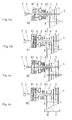
- Fig. 2a to 2d now different operating states of the dual clutch 1 and the hybrid drive are shown.
- Fig. 2a Both the first clutch K1 and the second clutch K2 of the dual clutch 1 are closed and the electric motor 5 is turned off.
- the equipped with the hybrid drive according to the invention motor vehicle drives purely internal combustion engine, at the same time the electric motor 5 can be used as a generator and an energy storage device, not shown, for example, a vehicle battery, can charge.
- the internal combustion engine 7 drives the input shaft 2, whose torque is transmitted to the intermediate shaft 6 due to the closed clutch K1. Since the intermediate shaft 6 is directly connected to the electric motor 5, the engine 7 also drives the electric motor 5. Due to the also closed second clutch K2 transmitted from the input shaft 2 to the intermediate shaft 6 torque is transmitted to the output shaft 4, which is drivingly connected to the transmission 3.
- Fig. 2b a loading operation state in which the motor vehicle equipped with the hybrid drive according to the invention is not moved.
- the torque is generated by the internal combustion engine 7 and transmitted to the input shaft 2. Since the clutch K1 is closed, the torque is transmitted to the intermediate shaft 6 and thus to the electric motor 5, which here is used exclusively as a generator for charging the vehicle battery.
- the second clutch K2 of the dual clutch 1 is opened, so that no torque is transmitted from the intermediate shaft 6 to the output shaft 4 or the transmission 3.
- an electric motor operating state is shown in which the motor vehicle is operated purely electrically.
- the electric motor 5 generates a torque, which it passes on to the intermediate shaft 6. Due to the closed clutch K2, the torque is transmitted from the intermediate shaft 6 to the output shaft 4 and thus to the transmission 3.
- the first clutch K1 is opened, so that no torque can be transmitted from the intermediate shaft 6 to the input shaft 2 and thus to the engine 7. It is conceivable, however, that to start the internal combustion engine 7, the first clutch K1 is closed and the second clutch K2 is at least slightly opened, so that the electric motor 5 can start or tow the combustion engine 7.
- a so-called boost operating state is shown, in which both the first clutch K1 and the second clutch K2 of the dual clutch 1 are closed and both the engine 7 and the electric motor 5 generate a torque.
- the torque generated by the engine 7 is transmitted via the input shaft 2 due to the closed clutch K1 to the intermediate shaft 6, which is driven by the electric motor 5 simultaneously.
- the cumulative torque at the intermediate shaft 6 is then transmitted to the output shaft 4 and thus to the transmission 3 due to the closed second clutch K2.
- Such a boost operating state can be useful, for example, if a particularly rapid acceleration of the motor vehicle is to be achieved or if the power of the electric motor 5, for example due to at least partially discharged batteries, no longer sufficient for driving the vehicle alone.
- a double clutch 1 according to the invention is shown, in which case extending between the electric motor 5 and a coaxial with the output shaft 4 to the transmission 3 out External output shaft 8, a third clutch K3 is arranged.
- the output shaft 4 of the double clutch 1 with a first group 9 of gears, for example, odd-numbered gears, and the external output shaft 8 with a second group 10 of gears, for example, with straight gears be drivingly connected.
- FIG. 4a an engine driving state is shown in which the two clutches K1 and K2 of the dual clutch 1 are closed while the third clutch K3 is opened.
- the electric motor 5 is switched off. From the engine 7, a torque is transmitted to the input shaft 2 and from there via the first clutch K1 to the intermediate shaft 6 and via the second clutch K2 to the output shaft 4.
- the output shaft 4 is preferably drivably connected to the first group 9 of gears, so for example, the odd gears. Since the intermediate shaft 6 and thus the electric motor 5 are also driven by the engine 7, in this operating state, the electric motor 5 can be used as a generator for charging the vehicle battery.
- a combustion drive state is shown in which the internal combustion engine 7, the second group 10 of gears, so for example, the even gears are driven.
- the first clutch K1 of the dual clutch 1 is closed, as well as the third clutch K3.
- the electric motor 5 is switched off.
- the operating state according to the Fig. 4b is transmitted from the engine 7, a torque to the input shaft 2 and the closed first clutch K1 of the dual clutch 1 to the intermediate shaft 6.
- the intermediate shaft 6 is drive-connected directly to the electric motor 5 and via the closed third clutch K3 to the external output shaft 8.
- the electric motor 5 can also be used as a generator for charging a vehicle battery.
- Driving in this operating state takes place exclusively internal combustion engine in the second group 10 of gears, for example in the even gears.
- Fig. 4c an electric drive state is shown in which only the second clutch K2 of the dual clutch 1 is closed while the first clutch K1 and the third clutch K3 are opened.
- the internal combustion engine 7 is switched off in this electric drive state.
- the electric motor 5 generates a torque which it transmits to the intermediate shaft 6 and via the closed clutch K2 to the output shaft 4.
- the output shaft 4 is in this case connectable to the first group 9 of gears.
- Fig. 4d is also shown an electric drive state in which the electric motor 5 generates a torque which it transmits due to the closed third clutch K3 to the external output shaft 8 and thus to the second group 10 of gears.
- the first clutch K1 and the second clutch K2 of the dual clutch 1 are opened, so that a transmission of torque from the intermediate shaft 6 can be done neither on the input shaft 2 nor on the output shaft 4.
- the internal combustion engine 7 may in an electric drive state according to the Fig. 4c and 4d the first clutch K1 of the dual clutch 1 are closed, so that the electric motor 5 tows the engine 7.
Landscapes
- Engineering & Computer Science (AREA)
- Chemical & Material Sciences (AREA)
- Combustion & Propulsion (AREA)
- Mechanical Engineering (AREA)
- Transportation (AREA)
- General Engineering & Computer Science (AREA)
- Automation & Control Theory (AREA)
- Hybrid Electric Vehicles (AREA)
- Electric Propulsion And Braking For Vehicles (AREA)
- Arrangement Of Transmissions (AREA)
- Structure Of Transmissions (AREA)
Abstract
Description
- Die vorliegende Erfindung betrifft eine Doppelkupplung für einen Hybrid-Antrieb eines Kraftfahrzeuges gemäß dem Oberbegriff des Anspruchs 1. Die Erfindung betrifft außerdem ein Kraftfahrzeug mit einer derartigen Doppelkupplung.
- Im allgemeinen bezeichnet ein Hybridfahrzeug ein Fahrzeug, welches eine Mehrzahl von Energiequellen verwendet, beispielsweise einen Verbrennungsmotor und einen Elektromotor. Um einen möglichst hohen energetischen Wirkungsgrad erzielen zu können, werden bei Hybridfahrzeugen üblicherweise so genannte Parallel-Hybrid-Antriebe eingesetzt, welche es ermöglichen, dass der Elektromotor und der Verbrennungsmotor nicht nur alternativ, sondern auch kumulativ Drehmoment in ein Getriebe einleiten. Im Unterschied zu einem Serien-Hybrid-Antrieb, bei welchem Energie zuerst von mechanischer Energie des Verbrennungsmotors in elektrische Energie umgewandelt und dann zum Betreiben des Elektromotors verwendet wird, arbeitet ein Parallel-Hybrid-Antrieb nicht immer an einem optimalen Arbeitspunkt, da der Verbrennungsmotor und der Elektromotor mechanisch miteinander durch ein Getriebe gekuppelt sind. Deshalb wird hier im Stand der Technik üblicherweise die Verwendung eines Doppelkupplungsgetriebes vorgeschlagen.
- Ein derartiges Doppelkupplungsgetriebe ist beispielsweise aus der
DE 10 2004 062 530 A1 bekannt, das so ausgebildet ist, dass es entsprechend eines jeweiligen Betriebszustandes unter Erreichung eines hohen Wirkungsgrades ein Drehmoment vom Elektromotor und/oder ein Drehmoment vom Verbrennungsmotor in den Antriebsstrang einleiten kann. - Die vorliegende Erfindung beschäftigt sich mit dem Problem, für eine Doppelkupplung der gattungsgemäßen Art eine verbesserte oder zumindest eine andere Ausführungsform anzugeben, welche insbesondere bei der Verwendung in einem Hybrid-Antrieb eine kompakte Bauform desselben erlaubt.
- Erfindungsgemäß wird dieses Problem durch den Gegenstand des unabhängigen Anspruchs 1 gelöst. Vorteilhafte Ausführungsformen sind Gegenstand der abhängigen Ansprüche.
- Die Erfindung beruht auf dem allgemeinen Gedanken, bei einem Parallel-Hybrid-Antrieb für ein Kraftfahrzeug zwei üblicherweise an- und abtriebseitig des Elektromotors angeordnete Kupplungen durch eine handelsübliche Doppelkupplung zu ersetzen und dadurch eine Baulänge des Antriebsstranges deutlich zu verkürzen. Die verwendete Doppelkupplung weist dabei eine, von einem Verbrennungsmotor antreibbare Eingangswelle und eine, mit einem Getriebe verbundene Ausgangswelle auf, wobei zusätzlich eine, von einem Elektromotor antreibbare koaxial zur Ausgangswelle verlaufende Zwischenwelle vorgesehen ist. Die Eingangswelle und die Zwischenwelle sind über eine erste Kupplung der Doppelkupplung miteinander kuppelbar, während die Zwischenwelle und die Ausgangswelle über eine zweite Kupplung der Doppelkupplung miteinander kuppelbar sind. Der Elektromotor ist dabei direkt mit der Zwischenwelle antriebsverbunden. Durch ein betriebszustandsabhängiges Öffnen bzw. Schließen der beiden Kupplungen der Doppelkupplung lassen sich somit einzelne Betriebszustände einfach realisieren. So kann beispielsweise rein verbrennungsmotorisch gefahren werden, sofern beide Kupplungen geschlossen sind und der Elektromotor nicht bestromt wird. In diesem Zustand kann der Elektromotor als Generator wirken und eine Energiespeichereinrichtung aufladen. Soll kein Antriebsmoment auf das Getriebe übertragen werden, so kann die zweite Kupplung geöffnet werden und über die geschlossene erste Kupplung der Elektromotor durch den Verbrennungsmotor angetrieben und zum Laden der Energiespeichereinrichtung verwendet werden. Bei einem rein elektrischen Fahren hingegen ist lediglich die zweite Kupplung geschlossen und die erste Kupplung geöffnet, so dass der Verbrennungsmotor vom Elektromotor abgekoppelt ist. In einem Boostbetrieb sind beide Kupplungen geschlossen und sowohl der Elektromotor als auch der Verbrennungsmotor leiten ein Drehmoment in das Getriebe ein.
- Zweckmäßig verläuft die Ausgangswelle koaxial durch den Elektromotor hindurch. Hierdurch kann eine besonders kompakte und bauraumminimierende Bauweise erreicht werden, da der Elektromotor im Unterschied zum Stand der Technik eng benachbart zur Doppelkupplung angeordnet und nicht abseits von dieser eingebaut ist, wodurch zusätzliche Drehmomentübertragungselemente vorgesehen werden müssten. Insbesondere letzteres spart auch Gewicht, was neben dem geringen Bauraumbedarf insbesondere im Sportwagenbau von besonderem Vorteil ist.
- Bei einer weiteren vorteilhaften Ausführungsform der erfindungsgemäßen Lösung ist die Eingangswelle koaxial zur Ausgangswelle angeordnet. Die koaxiale Ausrichtung der Eingangswelle zur Ausgangswelle bietet den großen Vorteil, dass keine Kraftumlenkung, beispielsweise mit Hilfe eines Kardangelenkes, erforderlich ist, und dadurch lediglich geringe Übertragungs- bzw. Übersetzungsverluste auftreten.
- Weitere wichtige Merkmale und Vorteile der Erfindung ergeben sich aus den Unteransprüchen, aus den Zeichnungen und aus der zugehörigen Figurenbeschreibung anhand der Zeichnungen.
- Es versteht sich, dass die vorstehend genannten und die nachstehend noch zu erläuternden Merkmale nicht nur in der jeweils angegebenen Kombination, sondern auch in anderen Kombinationen oder in Alleinstellung verwendbar sind, ohne den Rahmen der vorliegenden Erfindung zu verlassen.
- Bevorzugte Ausführungsbeispiele der Erfindung sind in den Zeichnungen dargestellt und werden in der nachfolgenden Beschreibung näher erläutert, wobei sich gleiche Bezugszeichen auf gleiche oder ähnliche oder funktional gleiche Bauteile beziehen.
- Dabei zeigen, jeweils schematisch,
- Fig. 1
- eine erfindungsgemäße Doppelkupplung für ein Hybridfahrzeug,
- Fig. 2a bis d
- unterschiedliche Betriebszustände der erfindungsgemäßen Doppelkupplung,
- Fig. 3
- eine erfindungsgemäße Doppelkupplung mit einer zusätzlichen dritten Kupplung,
- Fig. 4a bis d
- unterschiedliche Betriebszustände der erfindungsgemäßen Doppelkupplung mit der zusätzlichen dritten Kupplung.
- Entsprechend der
Fig. 1 weist eine erfindungsgemäße Doppelkupplung 1 für einen im übrigen nicht gezeigten Hybrid-Antrieb eines Kraftfahrzeuges, eine, von einem Verbrennungsmotor 7 antreibbare Eingangswelle 2 auf. Abtriebsseitig besitzt die Doppelkupplung 1 eine, mit einem Getriebe 3 verbundene Ausgangswelle 4. Die Eingangswelle 2 und die Ausgangswelle 4 sind dabei gemäß derFig. 1 koaxial zueinander angeordnet. Des Weiteren weist die Doppelkupplung 1 eine, von einem Elektromotor 5 antreibbare und koaxial zur Ausgangswelle 4 verlaufende Zwischenwelle 6 auf. Die Zwischenwelle 6 ist dabei ebenfalls koaxial zur Eingangswelle 2 bzw. zur Ausgangswelle 4 angeordnet. Des Weiteren ist die Zwischenwelle 6 vorzugsweise als Hohlwelle ausgebildet, innerhalb welcher die Ausgangswelle 4 verläuft.
Generell weist die Doppelkupplung 1 zwei Kupplungen, nämlich eine erste Kupplung K1 und eine zweite Kupplung K2 auf. Die erste Kupplung K1 ist dabei zwischen der Eingangswelle 2 und der Zwischenwelle 6 angeordnet und verbindet in geschlossenem Zustand die beiden Wellen 2 und 6. Über die zweite Kupplung K2 der Doppelkupplung 1 sind die Zwischenwelle 6 und die Ausgangswelle 4 miteinander kuppelbar. Der Elektromotor 5 ist dabei direkt mit der Zwischenwelle 6 verbunden. - Der Hybrid-Antrieb ist dabei vorzugsweise als Parallel-Hybrid-Antrieb ausgebildet, so dass der Verbrennungsmotor 7 und der Elektromotor 5 nicht nur alternativ, sondern auch kumulativ Drehmoment in das Getriebe 3 einleiten können.
- Durch die erfindungsgemäße Doppelkupplung 1 ist es möglich, eine serienmäßige Doppelkupplung in einen Hybrid-Antrieb zu integrieren und dadurch zwei bisher separat verbaute Kupplungen, welche üblicherweise antriebs- und abtriebsseitig des Elektromotors 5 angeordnet waren, einzusparen. Insbesondere erlaubt die erfindungsgemäße Doppelkupplung 1 eine deutlich kompaktere Bauweise des Antriebsstranges des Hybrid-Antriebes, was im Hinblick auf ein immer geringer werdendes Bauraumangebot von besonderem Vorteil ist.
- Gemäß den
Fig. 2a bis 2d sind nun unterschiedliche Betriebszustände der Doppelkupplung 1 bzw. des Hybrid-Antriebes gezeigt. InFig. 2a sind sowohl die erste Kupplung K1 als auch die zweite Kupplung K2 der Doppelkupplung 1 geschlossen und der Elektromotor 5 ist abgeschaltet. In diesem Zustand fährt das mit dem erfindungsgemäßen Hybrid-Antrieb ausgerüstete Kraftfahrzeug rein verbrennungsmotorisch, wobei gleichzeitig der Elektromotor 5 als Generator verwendet werden kann und eine nicht gezeigte Energiespeichereinrichtung, beispielsweise ein Fahrzeugbatterie, aufladen kann. Beim Betriebszustand gemäß derFig. 2a treibt somit der Verbrennungsmotor 7 die Eingangswelle 2 an, deren Drehmoment aufgrund der geschlossenen Kupplung K1 auf die Zwischenwelle 6 übertragen wird. Da die Zwischenwelle 6 direkt mit dem Elektromotor 5 verbunden ist, treibt der Verbrennungsmotor 7 auch den Elektromotor 5 an. Aufgrund der ebenfalls geschlossenen zweiten Kupplung K2 wird das von der Eingangswelle 2 auf die Zwischenwelle 6 übertragene Drehmoment an die Ausgangswelle 4 übertragen, welche mit dem Getriebe 3 antriebsverbunden ist. - Gemäß der
Fig. 2b ist ein Ladebetriebszustand gezeigt, in welchem das mit dem erfindungsgemäßen Hybrid-Antrieb ausgerüstete Kraftfahrzeug nicht bewegt wird. Das Drehmoment wird hierbei vom Verbrennungsmotor 7 erzeugt und auf die Eingangswelle 2 übertragen. Da die Kupplung K1 geschlossen ist, wird das Drehmoment an die Zwischenwelle 6 und damit an den Elektromotor 5 weitergegeben, welcher hier ausschließlich als Generator zum Aufladen der Fahrzeugbatterie verwendet wird. Die zweite Kupplung K2 der Doppelkupplung 1 ist geöffnet, so dass von der Zwischenwelle 6 kein Drehmoment auf die Ausgangswelle 4 bzw. das Getriebe 3 übertragen wird. - Gemäß der
Fig. 2c ist ein Elektromotor-Betriebszustand gezeigt, in welchem das Kraftfahrzeug rein elektrisch betrieben wird. Der Elektromotor 5 erzeugt hierbei ein Drehmoment, welches er an die Zwischenwelle 6 weitergibt. Aufgrund der geschlossenen Kupplung K2 wird das Drehmoment von der Zwischenwelle 6 auf die Ausgangswelle 4 und damit an das Getriebe 3 übertragen. Demgegenüber ist die erste Kupplung K1 geöffnet, so dass von der Zwischenwelle 6 kein Drehmoment an die Eingangswelle 2 und damit an den Verbrennungsmotor 7 übertragen werden kann. Denkbar ist jedoch, dass zu einem Starten des Verbrennungsmotors 7 die erste Kupplung K1 geschlossen und die zweite Kupplung K2 zumindest leicht geöffnet wird, so dass der Elektromotor 5 den Verbrennungsmotor 7 anlassen bzw. anschleppen kann. - In
Fig. 2d ist ein so genannter Boost-Betriebszustand gezeigt, bei welchem sowohl die erste Kupplung K1 als auch die zweite Kupplung K2 der Doppelkupplung 1 geschlossen sind und sowohl der Verbrennungsmotor 7 als auch der Elektromotor 5 ein Drehmoment erzeugen. Das vom Verbrennungsmotor 7 erzeugte Drehmoment wird dabei über die Eingangswelle 2 aufgrund der geschlossenen Kupplung K1 an die Zwischenwelle 6 übertragen, die gleichzeitig vom Elektromotor 5 angetrieben ist. Das kumulative Drehmoment an der Zwischenwelle 6 wird dann aufgrund der geschlossenen zweiten Kupplung K2 an die Ausgangswelle 4 und damit an das Getriebe 3 übertragen. Ein derartiger Boost-Betriebszustand kann beispielsweise dann sinnvoll sein, wenn eine besonders schnelle Beschleunigung des Kraftfahrzeuges erreicht werden soll oder wenn die Leistung des Elektromotors 5, beispielsweise aufgrund von zumindest teilweise entladenen Batterien, nicht mehr zum alleinigen Fahren des Kraftfahrzeuges ausreicht. - In
Fig. 3 ist eine erfindungsgemäße Doppelkupplung 1 gezeigt, wobei hier zwischen dem Elektromotor 5 und einer koaxial zur Ausgangswelle 4 zum Getriebe 3 hin verlaufenden Außenabtriebswelle 8 eine dritte Kupplung K3 angeordnet ist. Dabei kann die Ausgangswelle 4 der Doppelkupplung 1 mit einer ersten Gruppe 9 von Gängen, beispielsweise mit ungeraden Gängen, und die Außenabtriebswelle 8 mit einem zweiten Gruppe 10 von Gängen, beispielsweise mit geraden Gängen, antriebsverbunden sein. - In den
Fig. 4a bis 4d sind dabei wiederum unterschiedliche Betriebszustände gezeigt. GemäßFig. 4a ist ein Verbrennungsmotor-Antriebszustand gezeigt, in welchem die beiden Kupplungen K1 und K2 der Doppelkupplung 1 geschlossen sind, während die dritte Kupplung K3 geöffnet ist. Der Elektromotor 5 ist dabei abgeschaltet. Vom Verbrennungsmotor 7 wird ein Drehmoment auf die Eingangswelle 2 und von dieser über die erste Kupplung K1 an die Zwischenwelle 6 und über die zweite Kupplung K2 an die Ausgangswelle 4 übertragen. Die Ausgangswelle 4 ist dabei vorzugsweise mit der ersten Gruppe 9 von Gängen, also beispielsweise den ungeraden Gängen antriebsverbindbar. Da die Zwischenwelle 6 und damit der Elektromotor 5 ebenfalls vom Verbrennungsmotor 7 angetrieben werden, kann in diesem Betriebszustand der Elektromotor 5 als Generator zum Aufladen der Fahrzeugbatterie genutzt werden. - Gemäß
Fig. 4b ist ein Verbrennungsantriebszustand gezeigt, bei welchem vom Verbrennungsmotor 7 die zweite Gruppe 10 von Gängen, also beispielsweise die geraden Gänge, antreibbar sind. Hierzu ist die erste Kupplung K1 der Doppelkupplung 1 geschlossen, ebenso wie die dritte Kupplung K3. Der Elektromotor 5 ist abgeschaltet. In dem Betriebszustand gemäß derFig. 4b wird vom Verbrennungsmotor 7 ein Drehmoment auf die Eingangswelle 2 und über die geschlossene erste Kupplung K1 der Doppelkupplung 1 an die Zwischenwelle 6 übertragen. Die Zwischenwelle 6 ist direkt mit dem Elektromotor 5 und über die geschlossene dritte Kupplung K3 mit der Außenabtriebswelle 8 antriebsverbunden. In diesem Betriebszustand kann der Elektromotor 5 ebenfalls als Generator zum Laden einer Fahrzeugbatterie verwendet werden. Ein Fahren in diesem Betriebszustand erfolgt dabei ausschließlich verbrennungsmotorisch in der zweiten Gruppe 10 von Gängen, beispielsweise in den geraden Gängen. - In
Fig. 4c ist ein Elektroantriebszustand gezeigt, bei welchem ausschließlich die zweite Kupplung K2 der Doppelkupplung 1 geschlossen ist, während die erste Kupplung K1 und die dritte Kupplung K3 geöffnet sind. Der Verbrennungsmotor 7 ist in diesem Elektroantriebszustand abgeschaltet. Der Elektromotor 5 erzeugt dabei ein Drehmoment, welches er an die Zwischenwelle 6 und über die geschlossene Kupplung K2 an die Ausgangswelle 4 überträgt. Die Ausgangswelle 4 ist hierbei mit der ersten Gruppe 9 von Gängen verbindbar. - Gemäß der
Fig. 4d ist ebenfalls ein Elektroantriebszustand gezeigt, bei welchem der Elektromotor 5 ein Drehmoment erzeugt, welches er aufgrund der geschlossenen dritten Kupplung K3 an die Außenabtriebswelle 8 und damit an die zweite Gruppe 10 von Gängen überträgt. Die erste Kupplung K1 und die zweite Kupplung K2 der Doppelkupplung 1 sind geöffnet, so dass eine Übertragung eines Drehmomentes von der Zwischenwelle 6 weder auf die Eingangswelle 2 noch auf die Ausgangswelle 4 erfolgen kann. - Zum Wiederstarten des Verbrennungsmotors 7 kann bei einem Elektroantriebszustand gemäß den
Fig. 4c und 4d die erste Kupplung K1 der Doppelkupplung 1 geschlossen werden, so dass der Elektromotor 5 den Verbrennungsmotor 7 anschleppt. - Allen gezeigten Ausführungsformen der erfindungsgemäßen Doppelkupplung 1 ist dabei gemein, dass die Ausgangswelle 4 koaxial durch den Elektromotor 5 verläuft und dadurch eine besonders kompakte Bauweise erreicht werden kann.
Claims (13)
- Doppelkupplung (1) für einen Hybrid-Antrieb eines Kraftfahrzeugs,- mit einer von einem Verbrennungsmotor (7) antreibbaren Eingangswelle (2),- mit einer, mit einem Getriebe (3) verbundenen Ausgangswelle (4),- mit einer von einem Elektromotor (5) antreibbaren und koaxial zur Ausgangswelle (4) verlaufenden Zwischenwelle (6),- wobei die Eingangswelle (2) und die Zwischenwelle (6) über eine erste Kupplung (K1) der Doppelkupplung (1) miteinander kuppelbar sind,dadurch gekennzeichnet, dass die Zwischenwelle (6) und die Ausgangswelle (4) über eine zweite Kupplung (K2) der Doppelkupplung (1) miteinander kuppelbar sind.
- Doppelkupplung nach Anspruch 1, dadurch gekennzeichnet, dass die Eingangswelle (2) koaxial zur Ausgangswelle (4) angeordnet ist.
- Doppelkupplung nach Anspruch 1 oder 2, dadurch gekennzeichnet, dass der Hybrid-Antrieb als Parallel-Hybrid-Antrieb ausgebildet ist, so dass der Verbrennungsmotor (7) und der Elektromotor (5) nicht nur alternativ, sondern auch kumulativ Drehmoment in das Getriebe (3) einleiten können.
- Doppelkupplung nach einem der Ansprüche 1 bis 3, dadurch gekennzeichnet, dass in einem Verbrennungsantriebszustand die erste und die zweite Kupplung (K1, K2) der Doppelkupplung (1) geschlossen sind und der Elektromotor (5) abgeschaltet ist.
- Doppelkupplung nach einem der Ansprüche 1 bis 3, dadurch gekennzeichnet, dass in einem Elektroantriebszustand ausschließlich die erste Kupplung (K1) der Doppelkupplung (1) geschlossen ist.
- Doppelkupplung nach einem der Ansprüche 1 bis 3, dadurch gekennzeichnet, dass in einem Ladezustand zumindest die erste Kupplung (K1) der Doppelkupplung (1) geschlossen ist und der Elektromotor (5) als Generator zum Laden einer Energiespeichereinrichtung genutzt werden kann.
- Doppelkupplung nach einem der Ansprüche 1 bis 3, dadurch gekennzeichnet, dass in einem Boostzustand die erste und die zweite Kupplung (K1, K2) der Doppelkupplung (1) geschlossen sind und die Ausgangswelle (4) sowohl vom Verbrennungsmotor (7) als auch vom Elektromotor (5) angetrieben ist.
- Doppelkupplung nach einem der Ansprüche 1 bis 7, dadurch gekennzeichnet, dass zwischen dem Elektromotor (5) und einer koaxial zur Ausgangswelle (4) zum Getriebe (3) hin verlaufenden Außenabtriebswelle (8) eine dritte Kupplung (K3) angeordnet ist.
- Doppelkupplung nach Anspruch 8, dass die Ausgangswelle (4) der Doppelkupplung (1) mit einer ersten Gruppe (9) von Gängen und die Außenabtriebswelle (8) mit einer zweiten Gruppe (10) von Gängen des Getriebes (3) antriebsverbunden ist.
- Doppelkupplung nach Anspruch 9, dadurch gekennzeichnet, dass in einem Verbrennungsantriebszustand zum Antrieb des Getriebes (3) in einem Gang der ersten Gruppe (9) ausschließlich die erste und die zweite Kupplung (K1, K2) der Doppelkupplung (1) geschlossen sind und zum Antrieb des Getriebes (3) in einem Gang der zweiten Gruppe (10) ausschließlich die erste und die dritte Kupplung (K1, K3) der Doppelkupplung (1) geschlossen sind und der Elektromotor (5) jeweils abgeschaltet ist.
- Doppelkupplung nach Anspruch 9, dadurch gekennzeichnet, dass in einem Elektroantriebszustand zum Antrieb des Getriebes (3) in einem Gang der ersten Gruppe (9) ausschließlich die zweite Kupplung (K2) der Doppelkupplung (1) geschlossen ist und zum Antrieb des Getriebes (3) in einem Gang der zweiten Gruppe (10) ausschließlich die dritte Kupplung (K3) der Doppelkupplung (1) geschlossen ist, der Verbrennungsmotor (7) jeweils abgeschaltet ist.
- Doppelkupplung nach einem der Ansprüche 1 bis 11, dadurch gekennzeichnet, dass die Ausgangswelle (4) koaxial durch den Elektromotor (5) verläuft.
- Kraftfahrzeug mit einer Doppelkupplung (1) nach einem der Ansprüche 1 bis 12.
Applications Claiming Priority (1)
| Application Number | Priority Date | Filing Date | Title |
|---|---|---|---|
| DE102006058947A DE102006058947A1 (de) | 2006-12-14 | 2006-12-14 | Doppelkupplung für einen Hybrid-Antrieb |
Publications (2)
| Publication Number | Publication Date |
|---|---|
| EP1932741A2 true EP1932741A2 (de) | 2008-06-18 |
| EP1932741A3 EP1932741A3 (de) | 2011-03-23 |
Family
ID=39246875
Family Applications (1)
| Application Number | Title | Priority Date | Filing Date |
|---|---|---|---|
| EP07021058A Withdrawn EP1932741A3 (de) | 2006-12-14 | 2007-10-27 | Hybrid-Antrieb mit Doppelkupplung |
Country Status (6)
| Country | Link |
|---|---|
| US (1) | US7784573B2 (de) |
| EP (1) | EP1932741A3 (de) |
| JP (1) | JP4477666B2 (de) |
| KR (1) | KR101421730B1 (de) |
| CN (1) | CN101204921B (de) |
| DE (1) | DE102006058947A1 (de) |
Cited By (2)
| Publication number | Priority date | Publication date | Assignee | Title |
|---|---|---|---|---|
| CN103373225A (zh) * | 2012-04-17 | 2013-10-30 | 舍弗勒技术股份两合公司 | 用于机动车的传动系 |
| FR3021593A1 (fr) * | 2014-06-03 | 2015-12-04 | Peugeot Citroen Automobiles Sa | Module motopropulseur hybride comprenant trois accouplements debrayables et procede de pilotage du module |
Families Citing this family (24)
| Publication number | Priority date | Publication date | Assignee | Title |
|---|---|---|---|---|
| ITMO20050209A1 (it) * | 2005-08-05 | 2007-02-06 | Giorgio Bordini | Sistema di trazione ibrido |
| DE102006058947A1 (de) * | 2006-12-14 | 2008-06-19 | Dr.Ing.H.C. F. Porsche Ag | Doppelkupplung für einen Hybrid-Antrieb |
| JP5004289B2 (ja) * | 2007-08-02 | 2012-08-22 | 三菱ふそうトラック・バス株式会社 | ハイブリッド電気自動車の駆動装置 |
| JP2009292215A (ja) * | 2008-06-03 | 2009-12-17 | Aisin Ai Co Ltd | ハイブリッド車用動力伝達装置及びその変速操作方法 |
| DE102008041565A1 (de) * | 2008-08-26 | 2010-03-04 | Robert Bosch Gmbh | Verfahren zum Betreiben einer Hybridantriebsvorrichtung eines Kraftfahrzeugs sowie Hybridantriebsvorrichtung und elektronisches Steuergerät |
| ITBO20090061A1 (it) | 2009-02-09 | 2010-08-10 | Ferrari Spa | Veicolo stradale con propulsione ibrida |
| DE102009002176B4 (de) * | 2009-04-03 | 2017-07-20 | Robert Bosch Gmbh | Verfahren und Vorrichtung zum Betreiben eines Hybridfahrzeuges |
| US8056663B2 (en) * | 2009-06-12 | 2011-11-15 | GM Global Technology Operations LLC | Hybrid module for interconnecting an engine and a dual-clutch transmission |
| JP5309000B2 (ja) * | 2009-11-24 | 2013-10-09 | 本田技研工業株式会社 | ハイブリッド車両 |
| JP2011112130A (ja) * | 2009-11-26 | 2011-06-09 | Aisin Ai Co Ltd | 動力伝達装置 |
| DE102010008726A1 (de) * | 2010-02-20 | 2011-08-25 | Dr. Ing. h.c. F. Porsche Aktiengesellschaft, 70435 | Verfahren zum Betreiben eines Antriebssystems für ein Kraftfahrzeug |
| US8991579B2 (en) * | 2010-10-22 | 2015-03-31 | Exedy Corporation | Clutch device |
| US8795008B2 (en) | 2011-04-06 | 2014-08-05 | Twin Disc, Inc. | Two-into-two or one hybrid power device for a marine vehicle |
| DE102011089467B4 (de) | 2011-12-21 | 2023-10-05 | Zf Friedrichshafen Ag | Hybridantrieb eines Kraftfahrzeugs und Verfahren zum Betreiben desselben |
| DE102012109791A1 (de) * | 2012-10-15 | 2014-04-17 | Dr. Ing. H.C. F. Porsche Aktiengesellschaft | Verfahren zur Durchführung eines Boostbetriebes eines Hybrid-Fahrzeugs |
| DE102012112418A1 (de) * | 2012-12-17 | 2014-06-18 | Dr. Ing. H.C. F. Porsche Aktiengesellschaft | Verfahren zum Verteilen eines Wunschdrehmomentes |
| ITBO20130291A1 (it) | 2013-06-11 | 2014-12-12 | Ferrari Spa | Veicolo stradale con propulsione ibrida |
| WO2015152474A1 (ko) * | 2014-03-31 | 2015-10-08 | 강명구 | 피스톤 엔진과 로터리 엔진이 조합된 자동차의 동력전달장치 |
| CN105082992A (zh) * | 2014-04-18 | 2015-11-25 | 比亚迪股份有限公司 | 动力传动系统及具有该动力传动系统的车辆 |
| CN105291809B (zh) * | 2014-07-17 | 2018-09-07 | 广州汽车集团股份有限公司 | 一种电动汽车动力耦合系统及其控制方法 |
| KR102274073B1 (ko) * | 2016-10-06 | 2021-07-08 | 섀플러 테크놀로지스 아게 운트 코. 카게 | 하이브리드 모듈 |
| IT201800006198A1 (it) | 2018-06-11 | 2019-12-11 | Veicolo stradale con cambio a doppia frizione e con propulsione ibrida e relativo metodo di controllo | |
| DE102018009252A1 (de) * | 2018-11-24 | 2020-05-28 | Borgwarner Inc. | Dreifachkupplungseinrichtung und Antriebsstrang mit einer solchen Dreifachkupplungseinrichtung |
| DE102019202969A1 (de) * | 2019-03-05 | 2020-09-10 | Zf Friedrichshafen Ag | Hybrid-Getriebeanordnung für einen Kraftfahrzeugantriebsstrang sowie Verfahren zum Betreiben eines Hybrid-Antriebsstranges |
Citations (1)
| Publication number | Priority date | Publication date | Assignee | Title |
|---|---|---|---|---|
| DE102004062530A1 (de) | 2003-12-24 | 2005-10-06 | Hyundai Motor Company | Doppelkupplungsgetriebe für ein Hybrid-Elektrofahrzeug und Verfahren zum Betreiben desselben |
Family Cites Families (40)
| Publication number | Priority date | Publication date | Assignee | Title |
|---|---|---|---|---|
| US4463621A (en) * | 1981-12-23 | 1984-08-07 | Ford Motor Company | Multiple countershaft automatic transmission |
| DE4031571A1 (de) * | 1990-10-05 | 1992-04-09 | Daimler Benz Ag | Verfahren zum schalten eines mehrwege-zahnraederwechselgetriebes mit jeweils durch eine zahnradkupplung mit ihrer welle kuppelbaren losraedern |
| SE467426B (sv) * | 1990-11-01 | 1992-07-13 | Volvo Ab | Motorfordonsvaexellaada |
| JP3454036B2 (ja) * | 1995-11-13 | 2003-10-06 | トヨタ自動車株式会社 | ハイブリッド駆動装置 |
| JPH1014171A (ja) * | 1996-06-20 | 1998-01-16 | Nippon Soken Inc | ハイブリッド車のクラッチユニット |
| DE19711820A1 (de) * | 1996-08-08 | 1998-09-24 | Volkswagen Ag | Verfahren zum Schalten eines Doppelkupplungsgetriebes und Doppelkupplungsgetriebe |
| IT1295948B1 (it) * | 1997-11-04 | 1999-05-28 | Fiat Ricerche | Sistema motopropulsore per un autoveicolo. |
| EP0984202B1 (de) * | 1998-08-25 | 2002-07-31 | Ford Global Technologies, Inc., A subsidiary of Ford Motor Company | Wechselgetriebe in 3-Wellenbauweise, insbesondere für Kraftfahrzeuge |
| US7185722B1 (en) * | 2000-02-04 | 2007-03-06 | Hitachi, Ltd. | Power transmission apparatus of motor vehicles |
| CN1401060A (zh) * | 2000-02-15 | 2003-03-05 | 卢克摩擦片和离合器两合公司 | 转矩传递装置,尤其是具有复式离合器变速机构的转矩传递装置 |
| JP4199456B2 (ja) * | 2000-03-10 | 2008-12-17 | 株式会社日立製作所 | 自動変速機及びその制御装置 |
| DE10133695B4 (de) * | 2000-07-18 | 2015-08-13 | Schaeffler Technologies AG & Co. KG | Doppelkuplungsgetriebe |
| JP3711850B2 (ja) * | 2000-08-21 | 2005-11-02 | いすゞ自動車株式会社 | ハイブリッド駆動装置 |
| FR2814121B1 (fr) * | 2000-09-19 | 2003-02-14 | Peugeot Citroen Automobiles Sa | Groupe motopropulseur pour un vehicule automobile a propulsion hybride |
| US6460425B1 (en) * | 2001-01-10 | 2002-10-08 | New Venture Gear, Inc. | Twin clutch automated transmission |
| US6499370B2 (en) * | 2001-01-10 | 2002-12-31 | New Venture Gear, Inc. | Twin clutch automated transaxle with motor/generator synchronization |
| ATE361440T1 (de) * | 2001-01-12 | 2007-05-15 | Zf Sachs Ag | Kraftfahrzeug mit einem mehrfach- kupplungseinrichtung aufweisenden antriebsstrang |
| DE10290628D2 (de) * | 2001-02-23 | 2004-04-15 | Luk Lamellen & Kupplungsbau | Getriebe |
| DE10209514B4 (de) * | 2001-03-30 | 2016-06-09 | Schaeffler Technologies AG & Co. KG | Antriebsstrang |
| JP2003336701A (ja) * | 2002-05-22 | 2003-11-28 | Hitachi Ltd | 自動変速機 |
| DE10250853A1 (de) * | 2002-10-25 | 2004-05-19 | Getrag Getriebe- Und Zahnradfabrik Hermann Hagenmeyer Gmbh & Cie Kg | Antriebsstrang für ein Kraftfahrzeug sowie Verfahren zum Starten eines Verbrennungsmotors und Verfahren zum Generieren von elektrischem Strom |
| DE10360075A1 (de) * | 2003-01-09 | 2004-07-22 | Luk Lamellen Und Kupplungsbau Beteiligungs Kg | Parallelschaltgetriebe für Allradantrieb und Parallelschaltgetriebe für Quereinbau in ein Frontalantriebsfahrzeug |
| DE10325647A1 (de) * | 2003-06-06 | 2004-02-05 | Daimlerchrysler Ag | Doppelkupplungsgetriebe |
| DE10339758A1 (de) * | 2003-08-27 | 2005-06-09 | Daimlerchrysler Ag | Doppelkupplungsgetriebe in Windungsanordnung |
| US7082850B2 (en) * | 2003-12-30 | 2006-08-01 | Eaton Corporation | Hybrid powertrain system |
| JP4517694B2 (ja) * | 2004-03-22 | 2010-08-04 | 日産自動車株式会社 | ツインクラッチ式マニュアルトランスミッション |
| US7222686B2 (en) * | 2004-04-12 | 2007-05-29 | Tm4, Inc. | Drive train for series/parallel hybrid vehicle |
| FR2871106B1 (fr) * | 2004-06-03 | 2007-10-05 | Peugeot Citroen Automobiles Sa | Element de transmission a double embrayage pour chaine de traction hybride de vehicule automobile, procede de montage, et vehicule automobile equipe d'un tel element |
| JP4661131B2 (ja) * | 2004-08-18 | 2011-03-30 | 日産自動車株式会社 | 自動変速機の変速制御装置 |
| DE102004043386B4 (de) * | 2004-09-08 | 2013-02-21 | Zf Friedrichshafen Ag | Getriebevorrichtung in Vorgelegebauweise |
| EP1714816B1 (de) * | 2005-04-19 | 2008-04-09 | Getrag Ford Transmissions GmbH | Schaltgetriebe |
| EP1714817A1 (de) * | 2005-04-19 | 2006-10-25 | Getrag Ford Transmissions GmbH | Hybrid-Doppelkupplungsgetriebe |
| DE502005003092D1 (de) * | 2005-04-19 | 2008-04-17 | Getrag Ford Transmissions Gmbh | Doppelkupplungsgetriebe |
| DE102005035328B4 (de) * | 2005-07-28 | 2015-04-09 | Zf Friedrichshafen Ag | Doppelkupplungsgetriebe mit integrierter Elektromaschine und dessen Anwendung |
| DE102005063248B4 (de) * | 2005-12-21 | 2010-09-30 | Getrag Getriebe- Und Zahnradfabrik Hermann Hagenmeyer Gmbh & Cie Kg | Doppelkupplungsanordnung |
| US7462121B2 (en) * | 2006-05-12 | 2008-12-09 | Ford Global Technologies, Llc | Hybrid electric vehicle powertrain with four-wheel drive characteristics |
| US7490526B2 (en) * | 2006-05-22 | 2009-02-17 | Magna Powertrain Usa, Inc. | Dual clutch powershift transmission with transfer shaft |
| US7469609B2 (en) * | 2006-06-28 | 2008-12-30 | Ford Global Technologies, Llc | Output reduction dual clutch transmission with clutch coupler |
| US7611004B2 (en) * | 2006-08-07 | 2009-11-03 | Deere & Company | Control system and method for controlling an operational mode of a vehicle via multiple clutch assemblies |
| DE102006058947A1 (de) * | 2006-12-14 | 2008-06-19 | Dr.Ing.H.C. F. Porsche Ag | Doppelkupplung für einen Hybrid-Antrieb |
-
2006
- 2006-12-14 DE DE102006058947A patent/DE102006058947A1/de not_active Withdrawn
-
2007
- 2007-10-27 EP EP07021058A patent/EP1932741A3/de not_active Withdrawn
- 2007-12-13 US US11/955,829 patent/US7784573B2/en not_active Expired - Fee Related
- 2007-12-13 JP JP2007321458A patent/JP4477666B2/ja not_active Expired - Fee Related
- 2007-12-13 KR KR1020070129501A patent/KR101421730B1/ko not_active Expired - Fee Related
- 2007-12-14 CN CN2007103009351A patent/CN101204921B/zh not_active Expired - Fee Related
Patent Citations (1)
| Publication number | Priority date | Publication date | Assignee | Title |
|---|---|---|---|---|
| DE102004062530A1 (de) | 2003-12-24 | 2005-10-06 | Hyundai Motor Company | Doppelkupplungsgetriebe für ein Hybrid-Elektrofahrzeug und Verfahren zum Betreiben desselben |
Cited By (2)
| Publication number | Priority date | Publication date | Assignee | Title |
|---|---|---|---|---|
| CN103373225A (zh) * | 2012-04-17 | 2013-10-30 | 舍弗勒技术股份两合公司 | 用于机动车的传动系 |
| FR3021593A1 (fr) * | 2014-06-03 | 2015-12-04 | Peugeot Citroen Automobiles Sa | Module motopropulseur hybride comprenant trois accouplements debrayables et procede de pilotage du module |
Also Published As
| Publication number | Publication date |
|---|---|
| JP4477666B2 (ja) | 2010-06-09 |
| JP2008150033A (ja) | 2008-07-03 |
| CN101204921A (zh) | 2008-06-25 |
| KR20080055676A (ko) | 2008-06-19 |
| DE102006058947A1 (de) | 2008-06-19 |
| CN101204921B (zh) | 2013-08-21 |
| KR101421730B1 (ko) | 2014-07-22 |
| US20080142283A1 (en) | 2008-06-19 |
| EP1932741A3 (de) | 2011-03-23 |
| US7784573B2 (en) | 2010-08-31 |
Similar Documents
| Publication | Publication Date | Title |
|---|---|---|
| DE102006058947A1 (de) | Doppelkupplung für einen Hybrid-Antrieb | |
| DE102012009484B3 (de) | Doppelkupplungsgetriebe | |
| EP2608977B1 (de) | Hybridantriebsordnung für ein kraftfahrzeug | |
| DE102010010435A1 (de) | Antriebssystem und Verfahren zum Betreiben eines derartigen Antriebssystems, insbesondere für ein Kraftfahrzeug | |
| WO2009056193A2 (de) | Hybridfahrzeug mit doppelkupplungsgetriebe | |
| DE102020119290A1 (de) | Elektrische Antriebsvorrichtung für ein Fahrzeug | |
| DE102009039360A1 (de) | Hybridantriebsstrang für ein Kraftfahrzeug und Verfahren zu dessen Betrieb | |
| DE102019202967A1 (de) | Getriebeanordnung für einen Kraftfahrzeugantriebsstrang und Verfahren zum Betreiben einer Getriebeanordnung | |
| DE102008000953A1 (de) | Parallelhybridantriebsanordnung für ein Fahrzeug | |
| DE102019202969A1 (de) | Hybrid-Getriebeanordnung für einen Kraftfahrzeugantriebsstrang sowie Verfahren zum Betreiben eines Hybrid-Antriebsstranges | |
| DE102015201458A1 (de) | Hybrid-Antriebsstrang für ein Kraftfahrzeug | |
| DE102010008101A1 (de) | Doppelkupplungsgetriebe | |
| DE102009050956B4 (de) | Antriebsstrang für ein Allrad-Hybridfahrzeug mit zwei Verbrennungsmotoren sowie Verfahren zum Betrieb eines Antriebsstranges | |
| DE102013200826A1 (de) | Hybridantriebsystem für ein Kraftfahrzeug | |
| DE102016220512A1 (de) | Hybridantriebssystem für ein Transportmittel, insbesondere für ein Kraftfahrzeug | |
| DE102016100807A1 (de) | Hybridantriebsstrang für ein Kraftfahrzeug | |
| DE102021214535A1 (de) | Elektromotorisch und elektrodynamisch schaltbares Hybridgetriebe | |
| DE102012208678A1 (de) | Antriebsanordnung | |
| DE102011086062A1 (de) | Elektrifizierte Antriebsanordnung für ein Hybridfahrzeug | |
| DE102010007941B4 (de) | Hybridfahrzeug | |
| DE102020203774A1 (de) | Hybridgetriebe mit zwei Planetenradsätzen | |
| DE102022202926B4 (de) | Kompaktes Dreigang-Hybridgetriebe | |
| DE102019202970A1 (de) | Getriebeanordnung, Antriebsstrang und Verfahren zu dessen Betreiben | |
| DE102007004462A1 (de) | Hybridantriebsanordnung für ein Fahrzeug mit einem Antriebsstrang | |
| DE102014019431A1 (de) | Hybridantrieb für ein Fahrzeug |
Legal Events
| Date | Code | Title | Description |
|---|---|---|---|
| PUAI | Public reference made under article 153(3) epc to a published international application that has entered the european phase |
Free format text: ORIGINAL CODE: 0009012 |
|
| AK | Designated contracting states |
Kind code of ref document: A2 Designated state(s): AT BE BG CH CY CZ DE DK EE ES FI FR GB GR HU IE IS IT LI LT LU LV MC MT NL PL PT RO SE SI SK TR |
|
| AX | Request for extension of the european patent |
Extension state: AL BA HR MK RS |
|
| RAP1 | Party data changed (applicant data changed or rights of an application transferred) |
Owner name: DR. ING. H.C. F. PORSCHE AKTIENGESELLSCHAFT |
|
| RAP1 | Party data changed (applicant data changed or rights of an application transferred) |
Owner name: DR. ING. H.C. F. PORSCHE AG |
|
| PUAL | Search report despatched |
Free format text: ORIGINAL CODE: 0009013 |
|
| AK | Designated contracting states |
Kind code of ref document: A3 Designated state(s): AT BE BG CH CY CZ DE DK EE ES FI FR GB GR HU IE IS IT LI LT LU LV MC MT NL PL PT RO SE SI SK TR |
|
| AX | Request for extension of the european patent |
Extension state: AL BA HR MK RS |
|
| RIC1 | Information provided on ipc code assigned before grant |
Ipc: B60K 6/387 20071001ALI20110216BHEP Ipc: B60W 10/08 20060101ALN20110216BHEP Ipc: B60K 6/547 20071001ALI20110216BHEP Ipc: B60K 6/48 20071001ALI20110216BHEP Ipc: F16D 21/08 20060101ALI20110216BHEP Ipc: B60W 10/02 20060101ALN20110216BHEP Ipc: B60W 20/00 20060101AFI20080411BHEP Ipc: B60W 10/10 20060101ALN20110216BHEP Ipc: B60W 10/06 20060101ALN20110216BHEP |
|
| 17P | Request for examination filed |
Effective date: 20110923 |
|
| AKX | Designation fees paid |
Designated state(s): DE FR GB |
|
| RBV | Designated contracting states (corrected) |
Designated state(s): DE FR GB IT |
|
| GRAP | Despatch of communication of intention to grant a patent |
Free format text: ORIGINAL CODE: EPIDOSNIGR1 |
|
| INTG | Intention to grant announced |
Effective date: 20160803 |
|
| STAA | Information on the status of an ep patent application or granted ep patent |
Free format text: STATUS: THE APPLICATION IS DEEMED TO BE WITHDRAWN |
|
| 18D | Application deemed to be withdrawn |
Effective date: 20161214 |