EP1930613A1 - Ölschöpfanordnung zur Ölversorgung von zueinander drehenden Maschinenbauteilen - Google Patents
Ölschöpfanordnung zur Ölversorgung von zueinander drehenden Maschinenbauteilen Download PDFInfo
- Publication number
- EP1930613A1 EP1930613A1 EP07022246A EP07022246A EP1930613A1 EP 1930613 A1 EP1930613 A1 EP 1930613A1 EP 07022246 A EP07022246 A EP 07022246A EP 07022246 A EP07022246 A EP 07022246A EP 1930613 A1 EP1930613 A1 EP 1930613A1
- Authority
- EP
- European Patent Office
- Prior art keywords
- oil
- channel
- annular channel
- rotation
- housing
- Prior art date
- Legal status (The legal status is an assumption and is not a legal conclusion. Google has not performed a legal analysis and makes no representation as to the accuracy of the status listed.)
- Granted
Links
Images



Classifications
-
- F—MECHANICAL ENGINEERING; LIGHTING; HEATING; WEAPONS; BLASTING
- F16—ENGINEERING ELEMENTS AND UNITS; GENERAL MEASURES FOR PRODUCING AND MAINTAINING EFFECTIVE FUNCTIONING OF MACHINES OR INSTALLATIONS; THERMAL INSULATION IN GENERAL
- F16D—COUPLINGS FOR TRANSMITTING ROTATION; CLUTCHES; BRAKES
- F16D13/00—Friction clutches
- F16D13/58—Details
- F16D13/72—Features relating to cooling
-
- F—MECHANICAL ENGINEERING; LIGHTING; HEATING; WEAPONS; BLASTING
- F16—ENGINEERING ELEMENTS AND UNITS; GENERAL MEASURES FOR PRODUCING AND MAINTAINING EFFECTIVE FUNCTIONING OF MACHINES OR INSTALLATIONS; THERMAL INSULATION IN GENERAL
- F16D—COUPLINGS FOR TRANSMITTING ROTATION; CLUTCHES; BRAKES
- F16D25/00—Fluid-actuated clutches
- F16D25/12—Details not specific to one of the before-mentioned types
- F16D25/123—Details not specific to one of the before-mentioned types in view of cooling and lubrication
-
- F—MECHANICAL ENGINEERING; LIGHTING; HEATING; WEAPONS; BLASTING
- F16—ENGINEERING ELEMENTS AND UNITS; GENERAL MEASURES FOR PRODUCING AND MAINTAINING EFFECTIVE FUNCTIONING OF MACHINES OR INSTALLATIONS; THERMAL INSULATION IN GENERAL
- F16D—COUPLINGS FOR TRANSMITTING ROTATION; CLUTCHES; BRAKES
- F16D13/00—Friction clutches
- F16D13/58—Details
- F16D13/74—Features relating to lubrication
-
- F—MECHANICAL ENGINEERING; LIGHTING; HEATING; WEAPONS; BLASTING
- F16—ENGINEERING ELEMENTS AND UNITS; GENERAL MEASURES FOR PRODUCING AND MAINTAINING EFFECTIVE FUNCTIONING OF MACHINES OR INSTALLATIONS; THERMAL INSULATION IN GENERAL
- F16H—GEARING
- F16H57/00—General details of gearing
- F16H57/04—Features relating to lubrication or cooling or heating
- F16H57/042—Guidance of lubricant
- F16H57/0427—Guidance of lubricant on rotary parts, e.g. using baffles for collecting lubricant by centrifugal force
-
- F—MECHANICAL ENGINEERING; LIGHTING; HEATING; WEAPONS; BLASTING
- F16—ENGINEERING ELEMENTS AND UNITS; GENERAL MEASURES FOR PRODUCING AND MAINTAINING EFFECTIVE FUNCTIONING OF MACHINES OR INSTALLATIONS; THERMAL INSULATION IN GENERAL
- F16H—GEARING
- F16H57/00—General details of gearing
- F16H57/04—Features relating to lubrication or cooling or heating
- F16H57/0447—Control of lubricant levels, e.g. lubricant level control dependent on temperature
-
- F—MECHANICAL ENGINEERING; LIGHTING; HEATING; WEAPONS; BLASTING
- F16—ENGINEERING ELEMENTS AND UNITS; GENERAL MEASURES FOR PRODUCING AND MAINTAINING EFFECTIVE FUNCTIONING OF MACHINES OR INSTALLATIONS; THERMAL INSULATION IN GENERAL
- F16H—GEARING
- F16H57/00—General details of gearing
- F16H57/04—Features relating to lubrication or cooling or heating
- F16H57/042—Guidance of lubricant
- F16H57/0421—Guidance of lubricant on or within the casing, e.g. shields or baffles for collecting lubricant, tubes, pipes, grooves, channels or the like
- F16H57/0423—Lubricant guiding means mounted or supported on the casing, e.g. shields or baffles for collecting lubricant, tubes or pipes
-
- F—MECHANICAL ENGINEERING; LIGHTING; HEATING; WEAPONS; BLASTING
- F16—ENGINEERING ELEMENTS AND UNITS; GENERAL MEASURES FOR PRODUCING AND MAINTAINING EFFECTIVE FUNCTIONING OF MACHINES OR INSTALLATIONS; THERMAL INSULATION IN GENERAL
- F16H—GEARING
- F16H57/00—General details of gearing
- F16H57/04—Features relating to lubrication or cooling or heating
- F16H57/0457—Splash lubrication
-
- F—MECHANICAL ENGINEERING; LIGHTING; HEATING; WEAPONS; BLASTING
- F16—ENGINEERING ELEMENTS AND UNITS; GENERAL MEASURES FOR PRODUCING AND MAINTAINING EFFECTIVE FUNCTIONING OF MACHINES OR INSTALLATIONS; THERMAL INSULATION IN GENERAL
- F16H—GEARING
- F16H57/00—General details of gearing
- F16H57/04—Features relating to lubrication or cooling or heating
- F16H57/0467—Elements of gearings to be lubricated, cooled or heated
- F16H57/0473—Friction devices, e.g. clutches or brakes
-
- F—MECHANICAL ENGINEERING; LIGHTING; HEATING; WEAPONS; BLASTING
- F16—ENGINEERING ELEMENTS AND UNITS; GENERAL MEASURES FOR PRODUCING AND MAINTAINING EFFECTIVE FUNCTIONING OF MACHINES OR INSTALLATIONS; THERMAL INSULATION IN GENERAL
- F16H—GEARING
- F16H57/00—General details of gearing
- F16H57/04—Features relating to lubrication or cooling or heating
- F16H57/048—Type of gearings to be lubricated, cooled or heated
- F16H57/0493—Gearings with spur or bevel gears
- F16H57/0495—Gearings with spur or bevel gears with fixed gear ratio
Definitions
- the present invention relates to an oil scooping arrangement for supplying oil to a machine component rotating in a stationary housing about an axis of rotation and running in an oil sump or of machine components rotating relative to one another.
- the invention further relates to a multi-plate clutch with a ⁇ lschöpfan let the aforementioned type.
- a hydraulically actuated multi-plate clutch known.
- a piston which can be displaced axially in a hydraulic chamber is provided, which can exert an axial force on the disk pack.
- the hydraulic chamber is connected to a pump, which can act on the piston hydraulically.
- the hydraulic system comprises a common oil filling which serves both to actuate the piston and to cool the plate pack.
- a wet-running multi-plate clutch which comprises an outer disk carrier, are held in the outer disk rotatably, and an inner disk carrier, are rotatably mounted on the inner disk comprises.
- On the inner disc carrier a disc with Abstreifarmen is mounted, which promote oil on rotation through axial openings of the disc in the interior of the multi-plate clutch.
- the present invention has for its object to propose an improved oil extraction system, which ensures a reliable lubrication and cooling oil supply of rotating machine components, and in particular a multi-plate clutch to provide with improved lubrication and cooling capabilities.
- an oil scooping assembly for use in a stationary housing having machine components rotatable relative thereto about an axis of rotation, comprising an oil return member connectable to the housing and having a scraper for abutment against an outer surface of one of the machine components; at least one channel, which is supplied by the scraper with oil and which opens into a coaxial with the axis of rotation annular channel; and a ⁇ lschöpfrad connectable with one of the machine components with a plurality of wings distributed around the rotation axis, which dive into the annular channel and promote rotation of the ⁇ lschöpfrads relative to the oil return element oil from the annular channel.
- the advantage of the invention ⁇ lschöpfan ever is that the machine components are reliably supplied with rotation about the axis of rotation with oil.
- the design with stationary oil return element and with respect to this rotating ⁇ lschöpfrad is particularly effective because once arrived in the annular channel oil is forced through the wings of the ⁇ lschöpfrads mandatory in the interior of the machine component.
- the use of the scraper is particularly favorable because it can strip on the outer surface located oil on rotation of the machine component and can guide in the direction of the channel. In this way, a large volume of oil flow to the channel and thus ultimately to the rotating components, such as a multi-plate clutch, be promoted.
- the scraper preferably extends in the axial direction, wherein it is aligned in the assembled state along the outer surface of the rotating machine component and conforms to this.
- the scraper blade-like or C-shaped in cross-section which has a favorable effect on the strippable from the outer surface of oil.
- the ⁇ lschöpfrad is connectable to the same machine component, abutting on the outer surface of the scraper of the oil return element.
- Oil return element and ⁇ lschöpfrad act directly together.
- the scraper, the channel and the annular channel are made in one piece and together form the oil return element.
- the oil return element comprises a disc-shaped base body on which the radial channel, the annular channel and the wiper are mounted.
- the channel is preferably arranged on the base body, wherein a side wall of the channel is formed by the surface of the base body.
- the main body is preferably slightly conical.
- the annular channel has viewed in longitudinal section an approximately C-shaped profile which is open in the direction of the machine component, so that the wings of the ⁇ lschöpfrads can dip into the annulus.
- the annular channel is formed by an outer annular web, a coaxial inner annular web and a bottom, which is part of the base body.
- the radially inner end of the channel ends axially adjacent to the annular channel, wherein in the bottom of the annular channel a connecting aperture is provided.
- the aperture is preferably arranged in a radially inner portion of the bottom. In this way, an undercut is formed, which ensures that once reached in the annular channel oil can not escape to the outside.
- the ⁇ lschöpfrad comprises a ring on which the wings are mounted axially projecting.
- the ring preferably has axial apertures circumferentially adjacent to the vanes and through which the oil is pumped from the vanes toward the coupling.
- the wings are designed so that they promote oil upon rotation of the oil return element in the axial direction through the openings. For this they have a scoop-like shape in radial view.
- the ⁇ lschöpfrad with another machine component than the machine component, on which the oil return element abuts with its scraper, connectable is particularly suitable when the axial Connection options are limited to the rotating in the oil sump machine component.
- the scraper and the channel are made in one piece and together form the oil return element.
- the oil return element is connected according to a preferred embodiment with its channel to a connecting channel formed in the housing, which opens into the annular channel.
- the oil return element and the ⁇ lschöpfrad interact indirectly via the channels arranged in the housing.
- the annular channel is open in the housing radially inward, that is, the oil is carried out here from the annular channel in the interior of this coaxial machine component.
- the oil scoop wheel comprises a ring with radial apertures, the blades projecting like blades in the circumferential direction adjacent to the apertures of the ring to promote oil radially inwardly through the apertures upon rotation in a preferred direction of rotation.
- a multi-plate clutch with a ⁇ lschöpfan onion comprising a rotatable about an axis of rotation, running in an oil sump outer disk carrier with outer disks; a rotatably mounted relative to the outer disk carrier in a housing about the axis of rotation inner disk carrier with inner disks, wherein the inner disks and the outer disks are arranged axially alternately and form a disk set; an integrally formed on one of the two plate carrier base part with a plurality of circumferentially distributed axial apertures, which defines an annular coupling space formed between the two plate carriers; a with an integral with the housing oil return element having a voltage applied to an outer surface of the outer disk carrier above the oil sump scraper, connected to the scraper channel and a channel connected to the axis of rotation coaxial annular channel; and a ⁇ lschöpfrad associated with the bottom part with a plurality of circumferentially distributed, arranged in the region
- the multi-plate clutch according to the invention has the above-mentioned advantages of a reliable oil supply and thus good lubrication and cooling, resulting in a long life leads.
- the use of the stationary oil return element is particularly favorable, since gravity contributes to the fact that oil passes through the radial channel from the outer end to radially inward into the annular channel. Once in the annular channel oil is pumped through the wings of the rotating ⁇ lschöpfrads in the interior of the multi-plate clutch. By means of the scraper, a large amount of oil can be skimmed off the outer plate carrier and directed towards the channel.
- the oil-collecting unit used here may in particular have any of the configurations mentioned in connection with the first variant.
- the bottom part is firmly connected to the outer disk carrier, in particular designed in one piece.
- the axial openings, which connect the interior of the housing with the interior of the coupling, are preferably arranged in a radially inner portion of the bottom part. This ensures that the oil flows radially inward of the inner disc carrier so that it passes between the discs to lubricate and cool them.
- the inner disk carrier is preferably designed sleeve-shaped or in the form of a hollow shaft and has in the region of the disk set radial openings through which the oil can flow outwards to the disk set. It is mentioned here only for the sake of completeness, that the floor can of course also be connected to the inner disk carrier or designed in one piece with this.
- the bottom part radially inwardly has a hub which dips axially into the hollow shaft.
- a sealing ring is provided between one end of the inner disk carrier and the bottom.
- a multi-plate clutch with a ⁇ lschöpfan onion comprising a housing with a sleeve approach, in which radially inwardly to a rotational axis coaxial annular channel is formed; a rotatably mounted in the housing about the axis of rotation inner disk carrier with inner disks, wherein the inner disk carrier is designed sleeve-shaped and has a plurality of circumferentially distributed radial openings in the region of the annular channel; a rotatably mounted relative to the inner disk carrier about the axis of rotation, in an oil sump outer disk carrier with outer disks, wherein the inner disks and the outer disks are arranged axially alternately and form a disk set; a fixed to the housing oil return element having a voltage applied to an outer surface of the outer disk carrier above the oil sump scraper and connected to the scraper channel which is connected to the annular channel for oil supply; a connected to the inner disc carrier ⁇ l
- the sleeve projection has a connecting channel with an outer inlet opening, into which the channel opens, and an inner outlet opening, which opens into the annular channel on.
- the connecting channel in the installed state of the multi-plate clutch is aligned approximately vertically, so that the force of gravity can be exploited for oil supply.
- the sleeve-shaped inner disk carrier in the region of the disk pack has radial openings. It is particularly favorable for the oil lubrication of the multi-plate clutch when the inner diameter of the inner disk carrier increases from the plane of the first openings in the region of the ⁇ lschöpfrads to the level of the second openings in the region of the disk set.
- the outer disk carrier preferably has a one-piece integrally formed on this bottom part with a hub into which a shaft can be inserted rotatably.
- the outer disk carrier has a cylindrical outer surface, along which the scraper extends longitudinally.
- the scraper is aligned approximately parallel to the axis of rotation, outside the oil sump in an area above the coupling. Between the standing scraper and the rotating outer disc carrier a minimal gap is formed, so that friction losses are avoided.
- the components of the ⁇ lschöpfan onion can be made for example of plastic, in particular by injection molding, but also as metal parts from sheet metal.
- the ⁇ lschöpfrad can be connected to the associated machine component, for example by means of clips, press or screw.
- the oil return element is preferably supported axially via a shoulder arranged in the housing and thus aligned relative to the outer disk carrier. For attachment to the housing in particular screw or adhesive connections come into question.
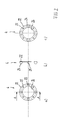
- FIGS. 1 and 2 will be described together below. They show a two-part oil scoop arrangement 2, which has an oil return element 3 and an oil scoop wheel 4 cooperating therewith.
- the oil return element 3 is inserted into a housing, not shown here, in which it is held stationary.
- the ⁇ lschöpfrad 4 is to be attached to a rotatably mounted in the housing machine component with which it rotates together about an axis of rotation relative to the stationary oil return element 3.
- the oil return element 3 comprises a disk-shaped main body 5, one mounted on the base body 5 and from radially outward to radially inwardly extending channel 6 and a radially inner annular channel 7, in which the radial channel 6 opens.
- the main body 5 is designed in the form of a conical disk and has in a radially outer peripheral portion a first axial opening 8, which serves as an access opening to the channel 6.
- Radially inside the main body 5 has a second axial opening 9, which serves as a connection of the channel 6 with the annular channel 7.
- the main body 5 further comprises a scraper 10, which is integrally formed on the cone disk and extending in the axial direction.
- the scraper 10 serves to abut against an outer surface of the rotating machine component in order to scrape off oil from the outer surface in a preferred direction of rotation during rotation of the machine component and to promote it in the direction of the access opening 8.
- the scraper 10 is designed in cross section approximately C-shaped and has an inner wall portion 12 which has a radius adapted to the radius of the outer surface of the machine component curvature, a rear wall 13 and an outer wall portion 14, which is at a radial distance from the inner wall portion 12th extends, about half its circumference extent.
- the free axial end of the scraper 10 is bevelled with respect to the longitudinal axis A.
- the access opening 8 and the opening 9 each have an approximately rectangular cross section, wherein the shape of the access opening 8 is adapted to the cross section of the scraper 10 and the inside of a concave and externally bounded by a convex edge approximately parallel thereto.
- the access opening 8 has a similar contour whose inner concave edge is adapted to the radius of the annular channel 7.
- the annular channel 7 has - viewed in longitudinal section - an approximately C-shaped profile and comprises an outer annular web 15, an inner annular web 16 for this purpose coaxial and a bottom 17 which is formed by the main body 5.
- the access opening 8 is formed in a radially inner portion of the bottom 17, namely adjacent to the inner annular web 16 so that once in the annular channel 7 reached oil can not flow back into the radial channel 6 due to centrifugal forces.
- the annular channel 7 is open in the axial direction to the machine component, so that the oil can be promoted by the ⁇ lschöpfrad 4 from the annular opening 18 thus formed in the interior of the machine component for cooling and lubrication purposes.
- the radial channel 6 is arranged on the disc-shaped main body 5, wherein the machine component facing side wall of the channel 6 is formed by the surface of the base body 5.
- the disc-shaped base body 5 is slightly conical, so that the channel 6 opens axially adjacent to the annular channel 7, wherein the access opening 8 and ring opening 18 lie in a common plane.
- Radially outward, the main body 5 has a flange portion 19 for axial support against a corresponding radial shoulder of the housing.
- at least one bore 20 is provided in the flange portion, in which a screw, not shown here, can be inserted and screwed into a corresponding threaded bore in the housing.
- the oil return element 3 with scraper 10, channel 6 and annular channel 7 is made in one piece from plastic, other materials are not excluded.
- the ⁇ lschöpfrad 4 as a detail in the FIGS. 2a) to 2c ), includes an annular disc 22 having circumferentially distributed apertures 23 and axially extending wings 24 each disposed adjacent to the apertures 23. Further circumferentially distributed holes 25 are provided which serve for axial attachment to the machine component, not shown here. It can be seen that the wings 24 have a scoop-like shape in radial view, so that they promote in rotation about the axis of rotation in a preferred direction of rotation oil in the associated respectively upstream in the circumferential direction opening 23. In the assembled state of the oil scoop arrangement 2, the circumferentially distributed vanes 24 engage in the annular channel 7 of the oil return element 3 in order to pump the oil located here into the interior of the machine component.
- the average diameter of the annular disc 22 corresponds approximately to the mean diameter of the annular channel 7.
- the radial width of the annular disc 22 and the wing 24 attached thereto is approximately the radial width of the annular channel 7, and the axial height of the wings 24 corresponds approximately to the axial depth of the annular channel 7, so that a total of the largest possible volume of oil flow from the annular channel 7 can be promoted in the interior of the machine component.
- the annular disc 22 has a central bore 26 through which a drive shaft, not shown here and can be connected to the machine component to pass.
- FIGS. 3 to 5 show a clutch assembly 32, in addition to the in the FIGS. 1 and 2 shown ⁇ lschöpfan angel 2 a multi-plate clutch 33 as a machine component, further comprises a Axialverstellvorraum 34 for actuating the multi-plate clutch 33 and an electric motor 61 for driving the Axialverstellvorraum 34.
- the clutch assembly 32 further includes a housing 35 in which the aforementioned components are received or attached to this.
- the multi-plate clutch 33 comprises two rotatable relative to each other about the axis of rotation A parts, namely an outer disk carrier 36, are rotatably and axially movably received in the outer disk 37, and an inner disk carrier 38, rotatably held on the inner disk 39 and axially movable.
- the outer disk 37 and the inner disk 39 are arranged axially alternately to each other and together form a disk set 40.
- the inner disk carrier 38 is designed in the form of a hollow shaft having a flange 42 at its free end for connection to a drive train, not shown.
- a plurality of radial apertures 41 are provided in the hollow shaft, through which cooling oil conveyed into the interior of the multi-disk clutch 33 can reach the clutch disks 37, 39.
- the inner disk carrier 38 is rotatably mounted relative to the housing 35 by means of a radial bearing 43 about the axis of rotation A and axially supported by means of a thrust bearing 44 relative to the housing 35.
- a radial shaft seal 45 is seated between the housing 35 and the inner disk carrier 38 a.
- the outer disk carrier 36 is cup-shaped and comprises a cylindrical shell portion, a bottom 46 and a hub 47 with an internal toothing.
- a connecting shaft (not shown, is to be inserted non-rotatably, which is to be stored with its free end in a stocked with a radial bearing 48 bore 49 of the inner disk carrier 38.
- the shell portion, the bottom 46 and the hub 47 are integrally formed and together form the clutch basket of the multi-disc clutch 33.
- the disk package 40 is axially supported on a fixedly connected to the inner disk carrier 38 supporting disk 50, which in turn against a seated in an annular groove of the inner disk carrier 38 Circlip 52 is axially supported.
- the disk set 40 is acted upon axially by a thrust washer 53, which in a corresponding recess of a pressure plate 54th is held.
- spring means 55 are effective in the form of disc springs, which act on the pressure plate 54 and the disk set 40 in axially opposite directions, that is in the opening direction of the multi-plate clutch 33 are effective.
- the spring means 55 are axially supported against a fixed relative to the inner disk carrier retaining ring 56.
- a sealing ring 51 in the form of a plastic ring, which prevents that promoted in the clutch basket cooling oil on the inside of the bottom flows radially outward without being in contact with the disk set get.
- Another purpose of the plastic ring 51 is to keep the outer disk carrier 36 axially spaced from the inner disk carrier 38.
- the oil scooping arrangement 2 In order to cool and lubricate the multi-plate clutch 33, the oil scooping arrangement 2 is provided, which conveys oil from the oil sump located in the housing 35 into the interior of the multidisk clutch 33. It can be seen that the oil return element 3 is axially supported with its flange portion 19 against a radial shoulder 27 of the housing 35 and fixed by means of at least one screw 28 to the housing 35. The screw 28 also serves as anti-rotation, so as to ensure that the scraper 10 is always held in the upper region of the housing 35 and the channel 6 leads vertically downwards.
- the annular channel 7 is coaxial with the axis of rotation A of the multi-plate clutch 33 and forms a central bore 29 through which the rotatably connected to the hub 47 shaft can pass.
- the ⁇ lschöpfrad 4 is fixed with its annular disc 22 on the bottom 46 of the outer disk carrier 36, preferably screwed.
- the screws 30, which are in FIG. 3 are visible, are screwed into threaded holes in the bottom 46.
- the bottom 46 and the annular disc 22 have opaque axial openings 23, 31 so that the cooling oil from the annular chamber 7 through the openings 23, 31 can enter the interior of the multi-plate clutch 33 to cool the plate pack 40 and the rotating components lubricate.
- the oil return element 3 is mounted in the housing 35 so that the scraper 10 is aligned parallel to the longitudinal axis A and thus along the outer surface of the outer disk carrier 36. In this way it is achieved that The surface 21 of the outer disk carrier 36 after passing through the oil sump adhering oil stripped on the scraper 10 and is directed to the access opening 8 in the channel 6. In order to direct as much oil in the channel 8, the scraper 10 extends in the axial direction over most of the outer disk carrier 36. For a maximum oil volume flow is further provided that the oil return element 3 is held in the housing 35 that between The radial gap formed by the wiper 10 and the outer disk carrier 36 is minimal. However, a touching contact between the scraper 10 and the cylindrical outer surface of the outer disk carrier 36 should be avoided in order to prevent friction losses.
- FIG. 5 The course of the cooling oil flow is in FIG. 5 illustrated by the arrows. It can be seen that the oil is stripped from the scraper 10 of the surface 21 of the outer disk carrier 36 and conveyed through the access opening 8 in the radial channel 6. Due to gravity, the oil flows in the radial channel 6 down and passes through the connection opening 9 in the annular channel 7. From here, the oil is pumped by the rotation of the ⁇ lschöpfrads 4 by means of the wings 24 through the apertures 31 into the interior of the multi-plate clutch. Here, the oil first flows in the axial direction within the designed as a hollow shaft inner disk carrier 38 to the radial openings 41.
- the oil passes due to the centrifugal forces through the openings 41 to the disk set 40, where it flows between the discs to the outside and thereby absorbs frictional heat of the clutch plates and transported away. Radially outward, the oil then flows through between the outer disk carrier 36 and the pressure plate 54 formed circumferential gap from the interior of the multi-plate clutch 33 in the interior of the housing 35 formed oil sump 11.
- the rotation of the outer disk carrier 36 in the oil sump 11 remains an oil film on the outer surface stick, which is transported up and stripped by the scraper 10. This is where the cycle starts from the beginning.
- Axleverstellvorraum 34 is designed in the form of a ball ramp assembly, with other actuating mechanisms, such as hydraulic actuators, are also conceivable.
- the ball ramp assembly 34 comprises two relatively rotatable discs, namely a support plate 57 and a control disc 58, of which the support plate 57 is axially supported relative to the stationary housing 35 and of which the adjusting disc 58 is axially displaceable.
- the two disks 57, 58 have in their mutually facing end faces a plurality of circumferentially distributed ball grooves 59, 60 with opposite slopes.
- Each two opposing ball grooves 59, 60 which extend in the circumferential direction, form a pair and each receive a ball over which the discs 57, 58 axially support.
- the balls are held in an axially between the two disks 57, 58 held cage 62 in the circumferential direction to each other.
- the balls are not visible because they are outside of the illustrated section plane.
- the depth of a pair of ball grooves 59, 60 is variable over the circumference, so that a rotation of the discs 57, 58 to each other to an axial displacement and thus an actuation of the pressure plate 54 of the multi-plate clutch 33 leads.
- the support disk 57 sits in a recess of the housing 35 against rotation.
- the adjusting disc 58 is mounted radially over the ball seats in the grooves with respect to the support disc 57 and rotatably driven via a toothed segment 63 about the axis of rotation A.
- Axial between the adjusting disc 58 and the pressure plate 54 is an axial bearing 64 interposed, which allows a transmission of the axial forces with simultaneous relative rotational movement.
- the two discs 57, 58 When fully opened friction clutch, the two discs 57, 58 are in the closest possible position to each other. With a corresponding rotation of the adjusting disk 58, the balls in the ball grooves 12, 13 run into areas of lesser depth. Thus, between the discs 57, 58, a spread takes place, wherein the adjusting disc 58 is axially displaced in the direction of the disk pack 40 and this applied via the thrust bearing 64 and the pressure plate 54. According to the rotation of the adjusting washer 58, the multi-plate clutch 33 is locked to a predetermined extent, and there is a coupling of the outer disk carrier 36 to the inner disk carrier 38. The designed as a plate springs spring means 55 cause the adjusting disk 58 with unconfirmed electric motor 61 back to its original position in Direction support plate 57 is moved.
- the ball ramp assembly 34 is drivable via a reduction stage 64 of the electric motor 61 which is flanged to the housing 35.
- the reduction stage 64 comprises a pinion 65 with two serrations 66, 67 which is rotatably mounted on a pin 68 parallel to the axis of rotation A.
- the spur gearing 66 of larger diameter is in meshing engagement with the drive shaft 69 of the electric motor 61, while the spur gearing 67 of smaller diameter meshes with the toothed segment 63 of the adjusting disc 58.
- the bolt 68 is seated with one end in a bore of the housing 35 and is held with its second end in a lid 70 inserted into the housing 35.
- the lid 70 is seated in a bore of the housing 35 a sealing.
- FIGS. 6 and 7 The following are the FIGS. 6 and 7 described together.
- the structure of the oil extraction unit 2 'shown here is similar to that of the FIGS. 1 and 2 , so that reference is made to the above description in terms of similarities. In the present case, the same or corresponding components are provided with primed by one.
- oil return element 3 ' forms together with in FIG. 7 shown ⁇ lschöpfrad 4 'together the ⁇ lschmüinheit 2'.
- the oil return element 3 ' is limited to its functional components. It comprises a scraper 10 'extending in the axial direction, which has a C-shaped profile viewed in cross-section, a tubular channel 6' adjoining it, and a fastening element 19 'on its upper side.
- the fastening element 19 ' is designed in the form of a radial projection which is to be brought into abutment against a shoulder in the housing and is to be fastened thereto by means of a screw connection.
- the tubular channel 6 ' has in the immediate connection to the scraper 10' first a first extending in the axial direction of the first channel portion 71, which merges into a radially extending second channel portion 72.
- the second channel section 72 serves to connect to a connecting channel, not shown here.
- the rear wall of the second channel section 72 is formed by a base body 5 ', which has a flattening on the inside radially to prevent rotation relative to a housing, not shown here.
- the ⁇ lschöpfrad 4 ' as a detail in the FIGS. 7a and 7b is shown, comprises an annular disc 22 'with a plurality of circumferentially distributed openings 23' and of the annular disc 22 'radially projecting wings 24', which are each adjacent in the circumferential direction to the openings 23 'are arranged. It can be seen that the wings 24 'in radial view have a scoop-shaped shape, so that they promote in rotation about the axis of rotation in a preferred direction of rotation oil in the respective forward in the circumferential direction opening 23' radially inward.
- the annular disc 22 ' has a central bore 26', so that it can be pushed onto a rotating machine component, in particular an inner disk carrier. In this case, the attachment to the machine component can be produced for example by means of a press fit or screw.
- FIGS. 8 and 9 show a coupling arrangement 32 'according to the invention in a second embodiment, which corresponds to that of the FIGS. 4 and 5 largely corresponds.
- the following section deals primarily with the differences.
- the longitudinal section through the coupling 32 ' is selected such that the electric motor 61' can be seen in the lower half of the picture, the structure and mode of operation being identical to that of FIG. 4 are.
- the present clutch assembly 32 ' is an oil scooping assembly 2' according to the FIGS. 6 and 7 for cooling and lubricating the multi-plate clutch 33 ', which conveys oil from the oil sump located in the housing 35' into the interior of the multi-plate clutch 33 '.
- the oil return element 3 ' is axially supported with its attachment portion 19' against a radial shoulder, not shown here, of the housing 35 'and fixed by means of screws relative thereto.
- the flattened body 5 ' serves to prevent rotation of the oil return element 3' relative to the sleeve extension 73, so that it is ensured that the scraper 10 'in a defined position in the upper region of the outer disk carrier 36' on the outer surface 21 'bears.
- the channel 6 'of the oil return element 3 ' opens into a sleeve in the approach from radially outward to radially inwardly extending connecting channel 74, which in turn opens into a radially inwardly open annular channel 7'.
- the connecting channel 74 is oriented approximately vertically, so that here inflowing oil can flow radially inward toward the annular channel 7 'due to gravity.
- the annular channel 7 ' is formed in a cylindrical inner surface 75 of the sleeve projection 73 and lies axially between the thrust bearing 44 and the support plate 57'. In this case, forms the radial contact surface of the support plate 57 ', with which it is axially supported relative to the housing 35', the side wall of the annular channel 7 '.
- the inner disk carrier 38 ' is largely designed in the form of a hollow shaft, at the first end Vietnamese tubular shaft, at the first end Vietnamese tubular shaft, and at its opposite second end, a flange 42 'is provided for connection to a drive train, not shown.
- the inner disk carrier In the axial overlap region with the annular channel 7 ', the inner disk carrier has a plurality of radial first openings 31' distributed over the circumference, which open into a cavity 77 formed in the sleeve-shaped inner disk carrier 38.
- the cavity 77 is axially closed by a web 78 in the direction of the flange 42 '.
- a plurality of radial second openings 41 are provided in the inner disk carrier 38, through which the cooling oil conveyed into the cavity 77 can reach the clutch disks 37', 39 '. It can be seen that the cavity 77 opens conically from the inlet region of the first openings 31 'in the direction of the second openings 41'. By this configuration it is achieved that the oil in the cavity 77 through the apertures 31 'reached upon rotation of the inner disk carrier 38' due to centrifugal forces in the direction of the second openings 41 'flows.
- the inner disk carrier 38' has a bearing shoulder 79 in which the shaft rotatably connected to the hub 47 'can be rotatably mounted on the axis of rotation A by means of a bearing 48'.
- the bearing shoulder 79 has at least one axially extending passageway 76.
- FIG. 9 The course of the cooling oil flow is in FIG. 9 illustrated by the arrows. It can be seen that the oil from the scraper 10 'from the surface 21' of the outer disk carrier 36 'is stripped and conveyed into the channel 6'. This opens into the housing 35 'formed in the connecting channel 74, where the oil flows due to gravity down and enters the annular channel 7'. From here, the oil is pumped by means of the wings 24 'through the apertures 31' into the interior of the inner disk carrier 38 'due to the rotation of the oil spout connected to the inner disk carrier 38. The conveying process takes place in the radial direction.
- the inner disk carrier and the housing are designed so that a promotion can be done by means of ⁇ lschöpfrads in the axial direction.
- the oil flows in the axial direction up to the radial second openings 41'.
- the oil passes through the second openings 41 'due to the centrifugal forces to the disk set 40', where it flows between the disks to the outside and thereby absorbs heat of friction of the clutch plates and transported away.
- Radially outward the oil then flows through between the outer disk carrier 36 'and the pressure plate 54' formed circumferential gap from the interior of the multi-plate clutch 33 'in the interior of the housing 35' formed in the oil sump 11 '.
- an oil film adheres to the outer surface 21 ', which is transported upwards and stripped by the scraper 10'. This is where the cycle starts from the beginning.
Landscapes
- Engineering & Computer Science (AREA)
- General Engineering & Computer Science (AREA)
- Mechanical Engineering (AREA)
- Hydraulic Clutches, Magnetic Clutches, Fluid Clutches, And Fluid Joints (AREA)
- General Details Of Gearings (AREA)
- Mechanical Operated Clutches (AREA)
Abstract
Description
- Die vorliegende Erfindung betrifft eine Ölschöpfanordnung zur Ölversorgung eines in einem stehenden Gehäuse um eine Drehachse rotierenden, in einem Ölsumpf laufenden Maschinenbauteil bzw. von zueinander rotierenden Maschinenbauteilen. Die Erfindung betrifft weiterhin eine Lamellenkupplung mit einer Ölschöpfanordnung der vorstehend genannten Art.
- Aus der
DE 103 49 030 B4 ist eine hydraulisch betätigte Lamellenkupplung bekannt. Zur Betätigung ist ein in einer Hydraulikkammer axial verschiebbarer Kolben vorgesehen, der auf das Lamellenpaket eine Axialkraft ausüben kann. Die Hydraulikkammer ist mit einer Pumpe verbunden, die den Kolben hydraulisch beaufschlagen kann. Das Hydrauliksystem umfaßt eine gemeinsame Ölfüllung, die sowohl zur Betätigung des Kolbens als auch zum Kühlen des Lamellenpakets dient. - Aus der
JP 11-082537 - Der vorliegenden Erfindung liegt die Aufgabe zugrunde, ein verbessertes Ölschöpfsystem vorzuschlagen, das eine zuverlässige Schmier- und Kühlölversorgung von rotierenden Maschinenbauteilen gewährleistet, sowie insbesondere eine Lamellenkupplung mit verbesserten Schmier- und Kühlmöglichkeiten bereitzustellen.
- Die Lösung hierfür besteht in einer Ölschöpfanordnung zur Verwendung in einem stehenden Gehäuse mit darin relativ zueinander um eine Drehachse drehbaren Maschinenbauteilen, umfassend ein mit dem Gehäuse verbindbares Ölrückführelement, das einen Abstreifer zum Anliegen an einer Außenfläche eines der Maschinenbauteile aufweist; zumindest einen Kanal, der vom Abstreifer mit Öl versorgt wird und der in einen zur Drehachse koaxialen Ringkanal mündet; und ein mit einem der Maschinenbauteile verbindbares Ölschöpfrad mit mehreren um die Drehachse verteilten Flügeln, die in den Ringkanal eintauchen und bei Drehung des Ölschöpfrads relativ zum Ölrückführelement Öl aus dem Ringkanal fördern.
- Der Vorteil der erfindungsgemäßen Ölschöpfanordnung besteht darin, daß die Maschinenbauteile bei Rotation um die Drehachse zuverlässig mit Öl versorgt werden. Die Ausgestaltung mit stehendem Ölrückführelement und gegenüber diesem drehenden Ölschöpfrad ist dabei besonders effektiv, da einmal in den Ringkanal gelangtes Öl durch die Flügel des Ölschöpfrads zwingend in den Innenraum des Maschinenbauteils gepumpt wird. Dadurch, daß das Ölrückführelement samt Abstreifer im Gehäuse ortsfest gehalten ist, wird ein gezielter Ölvolumenstrom erzeugt. Die Verwendung des Abstreifers ist besonders günstig, da dieser bei Rotation des Maschinenbauteils an dessen Außenfläche befindliches Öl abstreifen und in Richtung zum Kanal leiten kann. Hierdurch kann ein großer Ölvolumenstrom zum Kanal und damit letztlich zu den drehenden Bauteilen, beispielsweise einer Lamellenkupplung, gefördert werden.
- Der Abstreifer erstreckt sich vorzugsweise in axiale Richtung, wobei er in montiertem Zustand entlang der Außenfläche des drehenden Maschinenbauteils ausgerichtet ist und sich an dieser anschmiegt. Nach einer bevorzugten Ausgestaltung ist der Abstreifer im Querschnitt schaufelartig oder C-förmig gestaltet, was sich günstig auf die von der Außenfläche abstreifbare Ölmenge auswirkt. Die Ölschöpfanordnung ist so in dem stehenden Gehäuse zu befestigen, daß der radiale Kanal etwa vertikal ausgerichtet ist, so daß das Öl aufgrund der Schwerkraft nach radial innen in den Ringkanal läuft. Selbstverständlich können auch mehrere in radiale Richtung verlaufende Kanäle vorgesehen sein, die in den Ringraum münden.
- Nach einer ersten Variante ist das Ölschöpfrad mit demselben Maschinenbauteil verbindbar, an dessen Außenfläche der Abstreifer des Ölrückführelements anliegt. Ölrückführelement und Ölschöpfrad wirken dabei unmittelbar zusammen. Vorzugsweise sind der Abstreifer, der Kanal und der Ringkanal einteilig hergestellt und bilden gemeinsam das Ölrückführelement. Nach einer bevorzugten Ausgestaltung umfaßt das Ölrückführelement einen scheibenförmigen Grundkörper, an dem der radiale Kanal, der Ringkanal und der Abstreifer angebracht sind. Dabei ist der Kanal vorzugsweise auf dem Grundkörper angeordnet, wobei eine Seitenwand des Kanals durch die Oberfläche des Grundkörpers gebildet ist. Der Grundkörper ist vorzugsweise leicht konisch gestaltet. Der Ringkanal hat im Längsschnitt betrachtet ein etwa C-förmiges Profil, das in Richtung zum Maschinenbauteil geöffnet ist, so daß die Flügel des Ölschöpfrads in den Ringraum eintauchen können. Vorzugsweise wird der Ringkanal durch einen äußeren Ringsteg, einen hierzu koaxialen inneren Ringsteg und einen Boden gebildet, der Teil des Grundkörpers ist. Nach einer bevorzugten Ausgestaltung endet das radial innere Ende des Kanals axial benachbart zum Ringkanal, wobei im Boden des Ringkanals ein verbindender Durchbruch vorgesehen ist. Der Durchbruch ist vorzugsweise in einem radial innenliegenden Abschnitt des Bodens angeordnet. Auf diese Weise ist eine Hinterschneidung gebildet, die gewährleistet, daß einmal in den Ringkanal gelangtes Öl nicht mehr nach außen entweichen kann. Nach einer bevorzugten Ausgestaltung umfaßt das Ölschöpfrad einen Ring, an dem die Flügel axial abstehend angebracht sind. Bei Rotation des Maschinenbauteils laufen die Flügel in dem Ringkanal um die Drehachse um. Der Ring hat vorzugsweise axiale Durchbrüche, die in Umfangsrichtung benachbart zu den Flügeln angeordnet sind und durch die das Öl von den Flügeln in Richtung Kupplung gepumpt wird. Die Flügel sind derart gestaltet, daß sie bei Rotation des Ölrückführelements Öl in axiale Richtung durch die Durchbrüche fördern. Hierfür haben sie in Radialansicht eine schaufelartige Gestalt.
- Nach einer zweiten Variante ist das Ölschöpfrad mit einem anderen Maschinenbauteil als dem Maschinenbauteil, an dem das Ölrückführelement mit seinem Abstreifer anliegt, verbindbar. Diese Variante bietet sich insbesondere an, wenn die axialen Anschlußmöglichkeiten an das im Ölsumpf drehende Maschinenbauteil limitiert sind. Vorzugsweise sind der Abstreifer und der Kanal einteilig hergestellt und bilden gemeinsam das Ölrückführelement. Das Ölrückführelement ist nach einer bevorzugten Ausgestaltung mit seinem Kanal an einen im Gehäuse ausgebildeten Verbindungskanal angeschlossen ist, der in den Ringkanal mündet. Insofern wirken bei dieser Variante das Ölrückführelement und das Ölschöpfrad mittelbar über die im Gehäuse angeordneten Kanäle zusammen. Der Ringkanal ist im Gehäuse nach radial innen geöffnet, das heißt die Ölförderung erfolgt hier aus dem Ringkanal in den Innenraum des hierzu koaxialen Maschinenbauteils. Vorzugsweise umfaßt das Ölschöpfrad einen Ring mit radialen Durchbrüchen, wobei die Flügel in Umfangsrichtung benachbart zu den Durchbrüchen von dem Ring schaufelartig abstehen, um bei Rotation in einer Vorzugsdrehrichtung Öl durch die Durchbrüche nach radial innen zu fördern.
- Die Lösung der obengenannten Aufgabe besteht weiter in einer Lamellenkupplung mit einer Ölschöpfanordnung gemäß der ersten Variante, umfassend einen um eine Drehachse drehbaren, in einem Ölsumpf laufenden Außenlamellenträger mit Außenlamellen; einen relativ zum Außenlamellenträger in einem Gehäuse um die Drehachse drehbar gelagerten Innenlamellenträger mit Innenlamellen, wobei die Innenlamellen und die Außenlamellen axial abwechselnd angeordnet sind und ein Lamellenpaket bilden; ein an einen der beiden Lamellenträger angeformtes Bodenteil mit mehreren umfangsverteilten axialen Durchbrüchen, das einen zwischen den beiden Lamellenträgern gebildeten ringförmigen Kupplungsraum begrenzt; ein mit einem mit dem Gehäuse fest verbundenes Ölrückführelement, das einen oberhalb des Ölsumpfes an einer Außenfläche des Außenlamellenträgers anliegenden Abstreifer, einen mit dem Abstreifer verbundenen Kanal und einen mit dem Kanal verbundenen zur Drehachse koaxialen Ringkanal aufweist; und ein mit dem Bodenteil verbundenes Ölschöpfrad mit mehreren in Umfangsrichtung verteilten, im Bereich der Durchbrüche angeordneten Flügeln, die in den Ringkanal eintauchen und bei Drehung des Bodenteils relativ zum Gehäuse Öl aus dem Ringkanal durch die Durchbrüche in den Kupplungsraum fördern.
- Die erfindungsgemäße Lamellenkupplung hat die obengenannten Vorteile einer zuverlässigen Ölversorgung und damit einer guten Schmierung und Kühlung, was zu einer hohen Lebensdauer führt. Die Verwendung des stehenden Ölrückführelements ist besonders günstig, da die Schwerkraft so dazu beiträgt, daß Öl durch den radialen Kanal vom äußeren Ende nach radial innen in den Ringkanal läuft. Einmal in den Ringkanal gelangtes Öl wird durch die Flügel des drehenden Ölschöpfrads in den Innenraum der Lamellenkupplung gepumpt. Mittels dem Abstreifer kann eine große Ölmenge vom Außenlamellenträger abgeschöpft und in Richtung Kanal geleitet werden. Die hier verwendete Ölschöpfeinheit kann insbesondere jede der im Zusammenhang mit der ersten Variante genannten Ausgestaltungen aufweisen.
- Nach einer bevorzugten Ausgestaltung ist das Bodenteil mit dem Außenlamellenträger fest verbunden, insbesondere einteilig gestaltet. Die axialen Durchbrüche, die den Innenraum des Gehäuses mit dem Innenraum der Kupplung verbinden, sind vorzugsweise in einem radial innenliegenden Abschnitt des Bodenteils angeordnet. So wird gewährleistet, daß das Öl radial innerhalb des Innenlamellenträgers einströmt, so daß es zwischen die Lamellen gelangt, um diese zu schmieren und zu kühlen. Hierfür ist der Innenlamellenträger vorzugsweise hülsenförmig bzw. in Form einer Hohlwelle gestaltet und hat im Bereich des Lamellenpakets radiale Durchbrüche, durch die das Öl nach außen zum Lamellenpaket fließen kann. Es sei hier nur der Vollständigkeit halber erwähnt, daß der Boden selbstverständlich auch mit dem Innenlamellenträger verbunden bzw. einteilig mit diesem gestaltet sein kann. Nach einer bevorzugten Weiterbildung hat das Bodenteil radial innen eine Nabe, die in die Hohlwelle axial eintaucht. Vorzugsweise ist zwischen einem Ende des Innenlamellenträgers und dem Boden ein Dichtring vorgesehen. So wird verhindert, daß das in den Kupplungsraum einströmende Öl innen entlang des Bodens nach radial außen strömt, ohne mit den Lamellen in Kontakt zu kommen. Vielmehr wird erreicht, daß das Öl innerhalb des Innenlamellenträgers axial in den Bereich des Lamellenpakets strömt, um durch die radialen Durchbrüche zu den Lamellen zu gelangen. Das Öl strömt dann zwischen den Lamellen nach radial außen und verläßt den Kupplungsraum durch außenliegende Spalte wieder.
- Eine weitere Lösung der obengenannten Aufgabe besteht in einer Lamellenkupplung mit einer Ölschöpfanordnung gemäß der zweiten Variante, umfassend ein Gehäuse mit einem Hülsenansatz, in dem radial innen ein zu einer Drehachse koaxialer Ringkanal gebildet ist; einen im Gehäuse um die Drehachse drehbar gelagerten Innenlamellenträger mit Innenlamellen, wobei der Innenlamellenträger hülsenförmig gestaltet ist und im Bereich des Ringkanals mehrere umfangsverteilte radiale Durchbrüche aufweist; einen relativ zum Innenlamellenträger um die Drehachse drehbar gelagerten, in einem Ölsumpf laufenden Außenlamellenträger mit Außenlamellen, wobei die Innenlamellen und die Außenlamellen axial abwechselnd angeordnet sind und ein Lamellenpaket bilden; ein mit dem Gehäuse fest verbundenes Ölrückführelement, das einen oberhalb des Ölsumpfes an einer Außenfläche des Außenlamellenträgers anliegenden Abstreifer und einen mit dem Abstreifer verbundenen Kanal aufweist, der mit dem Ringkanal zur Ölversorgung verbunden ist; ein mit dem Innenlamellenträger verbundenes Ölschöpfrad mit mehreren umfangsverteilten Flügeln, die im Bereich der Durchbrüche angeordnet sind und in den Ringkanal eintauchen und bei Drehung des Innenlamellenträgers relativ zum Gehäuse Öl aus dem Ringkanal durch die Durchbrüche in den Kupplungsraum fördern. Diese Lamellenkupplung bietet in Analogie dieselben Vorteile, wie die obengenannte Lösung. Die hier verwendete Ölschöpfeinheit kann insbesondere jede der im Zusammenhang mit der zweiten Variante genannten Ausgestaltungen aufweisen.
- Nach einer bevorzugten Ausgestaltung weist der Hülsenansatz einen Verbindungskanal mit einer außenliegenden Eintrittsöffnung, in die der Kanal mündet, und einer innenliegenden Austrittsöffnung, die in den Ringkanal mündet, auf. Dabei ist der Verbindungskanal im Einbauzustand der Lamellenkupplung etwa vertikal ausgerichtet, so daß die Schwerkraft zur Ölversorgung ausgenutzt werden kann. Vorzugsweise hat der hülsenförmige Innenlamellenträger im Bereich des Lamellenpakets radiale Durchbrüche. Es ist für die Ölschmierung der Lamellenkupplung besonders günstig, wenn der Innendurchmesser des Innenlamellenträgers von der Ebene der ersten Durchbrüche im Bereich des Ölschöpfrads bis zur Ebene der zweiten Durchbrüche im Bereich des Lamellenpakets zunimmt. Auf diese Weise fließt das Öl bei Drehung des Innenlamellenträgers und damit einwirkender Zentrifugalkraft automatisch in Richtung größeren Querschnitts, das heißt in Richtung Lamellenpaket. Auch bei dieser Lösung weist der Außenlamellenträger vorzugsweise ein hieran einteilig angeformtes Bodenteil mit einer Nabe auf, in die eine Welle drehfest eingesteckt werden kann.
- Nach einer bevorzugten Ausführungsform, die für beide obengenannte Lösungen gilt, hat der Außenlamellenträger eine zylindrische Außenfläche, entlang derer sich der Abstreifer längs erstreckt. Dabei ist der Abstreifer etwa parallel zur Drehachse ausgerichtet, und zwar außerhalb des Ölsumpfs in einem Bereich oberhalb der Kupplung. Zwischen dem stehenden Abstreifer und dem drehenden Außenlamellenträger ist ein minimaler Spalt gebildet, so daß Reibungsverluste vermieden werden. Die Bauteile der Ölschöpfanordnung können beispielsweise aus Kunststoff, insbesondere im Spritzgußverfahren, aber auch als Umformteile aus Blech hergestellt werden. Das Ölschöpfrad kann mit dem zugehörigen Maschinenbauteil beispielsweise mittels clipsen, pressen oder schrauben verbunden sein. Das Ölrückführelement ist vorzugsweise über eine im Gehäuse angeordnete Schulter axial abgestützt und somit relativ zum Außenlamellenträger ausgerichtet. Zur Befestigung mit dem Gehäuse kommen insbesondere Schraub- oder Klebeverbindungen in Frage.
- Bevorzugte Ausführungsbeispiele der Erfindung sind in den Zeichnungsfiguren dargestellt und werden nachstehend beschrieben. Es zeigt
- Figur 1
- ein Ölrückführelement einer erfindungsgemäßen Ölschöpfanordnung in einer ersten Ausführungsform
- a) in axialer Vorderansicht;
- b) im Längsschnitt gemäß Schnittlinie A-A nach Darstellung 1a);
- c) in axialer Rückansicht;
- Figur 2
- ein Ölschöpfrad für ein Ölrückführelement aus
Figur 1 - a) in axialer Vorderansicht;
- b) im Längsschnitt gemäß Schnittlinie A-A nach Darstellung 2a);
- c) in axialer Rückansicht;
- Figur 3
- eine erfindungsgemäße Lamellenkupplung in einer ersten Ausführungsform mit einer Ölschöpfanordnung gemäß den
Figuren 1 und2 in Explosionsdarstellung im Längsschnitt; - Figur 4
- die Lamellenkupplung gemäß
Figur 3 in fertig montiertem Zustand im Längsschnitt; - Figur 5
- die Lamellenkupplung aus
Figur 4 mit eingezeichnetem Verlauf des Ölflusses; - Figur 6
- ein Ölrückführelement einer erfindungsgemäßen Ölschöpfanordnung in einer zweiten Ausführungsform
- a) in axialer Rückansicht;
- b) im Längsschnitt gemäß Schnittlinie A-A nach Darstellung 6a);
- c) im Querschnitt gemäß Schnittlinie B-B nach Darstellung 6b);
- Figur 7
- ein Ölschöpfrad für ein Ölrückführelement nach
Figur 6 - a) im Querschnitt;
- b) im Längsschnitt;
- Figur 8
- eine erfindungsgemäße Lamellenkupplung in einer zweiten Ausführungsform mit einer Ölschöpfanordnung gemäß den
Figuren 6 und7 im Längsschnitt; - Figur 9
- die Lamellenkupplung aus
Figur 8 mit eingezeichnetem Verlauf des Ölflusses; - Die
Figuren 1 und2 werden im folgenden gemeinsam beschrieben. Sie zeigen eine zweiteilige Ölschöpfanordnung 2, die ein Ölrückführelement 3 und ein hiermit zusammenwirkendes Ölschöpfrad 4 aufweist. Das Ölrückführelement 3 wird in ein hier nicht dargestelltes Gehäuse eingesetzt, in dem es ortsfest gehalten wird. Das Ölschöpfrad 4 ist an einem in dem Gehäuse drehbar gelagerten Maschinenbauteil anzubringen, mit dem es gemeinsam um eine Drehachse relativ zu dem stehenden Ölrückführelement 3 rotiert. - Das Ölrückführelement 3, das als Einzelheit in den
Figuren 1a) bis 1c ) dargestellt ist, umfaßt einen scheibenförmigen Grundkörper 5, einen auf dem Grundkörper 5 angebrachten und von radial außen nach radial innen verlaufenden Kanal 6 sowie einen radial innenliegenden Ringkanal 7, in den der Radialkanal 6 mündet. Der Grundkörper 5 ist in Form einer Konusscheibe gestaltet und hat in einem radial außenliegenden Umfangsabschnitt einen ersten axialen Durchbruch 8, der als Zutrittsöffnung zum Kanal 6 dient. Radial innen hat der Grundkörper 5 einen zweiten axialen Durchbruch 9, der als Verbindung des Kanals 6 mit dem Ringkanal 7 dient. Der Grundkörper 5 umfaßt weiter einen Abstreifer 10, der an die Konusscheibe angeformt ist und sich in axiale Richtung erstreckt. Der Abstreifer 10 dient dazu, an einer Außenfläche des rotierenden Maschinenbauteils anzuliegen, um bei Rotation des Maschinenbauteils in einer Vorzugsdrehrichtung Öl von der Außenfläche abzuschöpfen und in Richtung der Zutrittsöffnung 8 zu fördern. Hierfür ist der Abstreifer 10 im Querschnitt etwa C-Förmig gestaltet und hat einen inneren Wandungsabschnitt 12, der eine an den Radius der Außenfläche des Maschinenbauteils angepaßte Krümmung aufweist, eine Rückwand 13 und einen äußeren Wandungsabschnitt 14, der sich mit radialem Abstand zum inneren Wandungsabschnitt 12 erstreckt, und zwar etwa über dessen halbe Umfangserstreckung. Das freie axiale Ende des Abstreifers 10 ist gegenüber der Längsachse A abgeschrägt. - Es ist ersichtlich, daß die Zutrittsöffnung 8 und der Durchbruch 9 jeweils einen etwa rechteckigen Querschnitt haben, wobei die Gestalt der Zutrittsöffnung 8 an den Querschnitt des Abstreifers 10 angepaßt ist und innen von einer konkaven und außen von einer hierzu etwa parallelen konvexen Kante begrenzt ist. Die Zutrittsöffnung 8 hat eine ähnliche Kontur, deren innere konkave Kante an den Radius des Ringkanals 7 angepaßt ist. Der Ringkanal 7 hat - im Längsschnitt betrachtet - ein etwa C-förmiges Profil und umfaßt einen äußeren Ringsteg 15, einen hierzu koaxialen inneren Ringsteg 16 und einen Boden 17, der durch den Grundkörper 5 gebildet wird. Dabei ist die Zutrittsöffnung 8 in einem radial innenliegenden Abschnitt des Bodens 17, und zwar benachbart zum inneren Ringsteg 16 gebildet, damit einmal in den Ringkanal 7 gelangtes Öl aufgrund von Zentrifugalkräften nicht wieder in den Radialkanal 6 zurückfließen kann. Der Ringkanal 7 ist in axiale Richtung zum Maschinenbauteil hin offen, so daß das Öl von dem Ölschöpfrad 4 aus der so gebildeten Ringöffnung 18 in das Innere des Maschinenbauteils zu Kühl- und Schmierzwecken gefördert werden kann.
- Der radiale Kanal 6 ist auf dem scheibenförmigen Grundkörper 5 angeordnet, wobei die dem Maschinenbauteil zugewandte Seitenwand des Kanals 6 durch die Oberfläche des Grundkörpers 5 gebildet ist. Der scheibenförmige Grundkörper 5 ist leicht konisch gestaltet, so daß der Kanal 6 axial benachbart zum Ringkanal 7 mündet, wobei die Zutrittsöffnung 8 und Ringöffnung 18 in einer gemeinsamen Ebene liegen. Radial außen hat der Grundkörper 5 einen Flanschabschnitt 19 zum axialen Abstützen gegen eine entsprechende radiale Schulter des Gehäuses. Zur Verdrehsicherung sind ist in dem Flanschabschnitt zumindest eine Bohrung 20 vorgesehen, in die eine hier nicht dargestellte Schraube eingesteckt und in eine entsprechende Gewindebohrung im Gehäuse eingedreht werden kann. Das Ölrückführelement 3 mit Abstreifer 10, Kanal 6 und Ringkanal 7 ist einteilig aus Kunststoff hergestellt, wobei andere Materialien nicht ausgeschlossen sind.
- Das Ölschöpfrad 4, das als Einzelheit in den
Figuren 2a) bis 2c ) dargestellt ist, umfaßt eine Ringscheibe 22 mit umfangsverteilten Öffnungen 23 und axial abstehenden Flügeln 24, die jeweils benachbart zu den Öffnungen 23 angeordnet sind. Weiter sind umfangsverteilte Bohrungen 25 vorgesehen, die zur axialen Befestigung an dem hier nicht dargestellten Maschinenbauteil dienen. Es ist ersichtlich, daß die Flügel 24 in Radialansicht eine schaufelförmige Gestalt aufweisen, so daß sie bei Rotation um die Drehachse in einer Vorzugsdrehrichtung Öl in die zugehörige jeweils in Umfangsrichtung davorliegende Öffnung 23 fördern. In montiertem Zustand der Ölschöpfanordnung 2 greifen die umfangsverteilten Flügel 24 in den Ringkanal 7 des Ölrückführelements 3 ein, um das hier befindliche Öl in den Innenraum des Maschinenbauteils zu pumpen. Demnach entspricht der mittlere Durchmesser der Ringscheibe 22 etwa dem mittleren Durchmesser des Ringkanals 7. Weiter beträgt die radiale Breite der Ringscheibe 22 und der hierauf befestigten Flügel 24 etwa der radialen Breite des Ringkanals 7, und die axiale Höhe der Flügel 24 entspricht etwa der axialen Tiefe des Ringkanals 7, so daß insgesamt ein möglichst größer Ölvolumenstrom aus dem Ringkanal 7 in das Innere des Maschinenbauteils gefördert werden kann. Die Ringscheibe 22 hat eine zentrale Bohrung 26, durch die eine hier nicht dargestellte und mit dem Maschinenbauteil zu verbindende Antriebswelle hindurchtreten kann. - Die
Figuren 3 bis 5 , die im folgenden gemeinsam beschrieben werden, zeigen eine Kupplungsanordnung 32, die neben der in denFiguren 1 und2 gezeigten Ölschöpfanordnung 2 eine Lamellenkupplung 33 als Maschinenbauteil, ferner eine Axialverstellvorrichtung 34 zum Betätigen der Lamellenkupplung 33 sowie einen Elektromotor 61 zum Ansteuern der Axialverstellvorrichtung 34 aufweist. Die Kupplungsanordnung 32 umfaßt weiter ein Gehäuse 35, in dem die vorstehend genannten Bauteile aufgenommen bzw. an diesem angebracht sind. - Die Lamellenkupplung 33 umfaßt zwei relativ zueinander um die Drehachse A drehbare Teile, nämlich einen Außenlamellenträger 36, in dem Außenlamellen 37 drehfest und axial beweglich aufgenommen sind, und einen Innenlamellenträger 38, an dem Innenlamellen 39 drehfest und axial beweglich gehalten sind. Die Außenlamellen 37 und die Innenlamellen 39 sind axial abwechselnd zueinander angeordnet und bilden gemeinsam ein Lamellenpaket 40. Der Innenlamellenträger 38 ist in Form einer Hohlwelle gestaltet, die an ihrem freien Ende einen Flansch 42 zum Anschließen an einen nicht dargestellten Antriebsstrang aufweist. Im Bereich des Lamellenpakets 40 sind mehrere radiale Durchbrüche 41 in der Hohlwelle vorgesehen, durch die in den Innenraum der Lamellenkupplung 33 gefördertes Kühlöl zu den Kupplungslamellen 37, 39 gelangen kann. Der Innenlamellenträger 38 ist gegenüber dem Gehäuse 35 mittels eines Radiallagers 43 um die Drehachse A drehbar gelagert und mittels eines Axiallagers 44 gegenüber dem Gehäuse 35 axial abgestützt. Zum Abdichten sitzt ein Radialwellendichtring 45 zwischen dem Gehäuse 35 und dem Innenlamellenträger 38 ein. Der Außenlamellenträger 36 ist topfförmig gestaltet und umfaßt einen zylindrischen Mantelabschnitt, einen Boden 46 und eine Nabe 47 mit einer Innenverzahnung. In die Nabe 47 ist eine nicht dargestellte Anschlußwelle drehfest einzustecken, die mit ihrem freien Ende in einer mit Radiallager 48 bestückten Bohrung 49 des Innenlamellenträgers 38 zu lagern ist. Der Mantelabschnitt, der Boden 46 und die Nabe 47 sind einteilig gestaltet und bilden gemeinsam den Kupplungskorb der Lamellenkupplung 33. Das Lamellenpaket 40 ist an einer mit dem Innenlamellenträger 38 fest verbundenen Stützscheibe 50 axial abgestützt, die ihrerseits gegen einen in einer Ringnut des Innenlamellenträgers 38 einsitzenden Sicherungsring 52 axial abgestützt ist. Das Lamellenpaket 40 wird von einer Druckscheibe 53 axial beaufschlagt, die in einer entsprechenden Ausnehmung einer Druckplatte 54 gehalten ist. Zwischen der Druckplatte 54 und dem Innenlamellenträger 38 sind Federmittel 55 in Form von Tellerfedern wirksam, die die Druckplatte 54 und das Lamellenpaket 40 in axial entgegengesetzte Richtungen beaufschlagen, das heißt im Öffnungssinn der Lamellenkupplung 33 wirksam sind. Die Federmittel 55 sind gegen einen gegenüber dem Innenlamellenträger fixierten Sicherungsring 56 axial abgestützt. Zwischen dem Boden 46 des Außenlamellenträgers 36 und dem hierzu benachbarten Ende des Innenlamellenträgers 38 sitzt ein Dichtring 51 in Form eines Kunststoffrings ein, der verhindert, daß in den Kupplungskorb gefördertes Kühlöl an der Innenseite des Bodens nach radial außen fließt, ohne mit dem Lamellenpaket in Kontakt zu kommen. Eine weiterer Zweck des Kunststoffrings 51 ist es, den Außenlamellenträger 36 axial beabstandet vom Innenlamellenträger 38 zu halten.
- Um die Lamellenkupplung 33 zu kühlen und zu schmieren, ist die Ölschöpfanordnung 2 vorgesehen, welche Öl aus dem im Gehäuse 35 befindlichen Ölsumpf in das Innere der Lamellenkupplung 33 fördert. Es ist ersichtlich, daß das Ölrückführelement 3 mit seinem Flanschabschnitt 19 gegen eine radiale Schulter 27 des Gehäuses 35 axial abgestützt und mittels zumindest einer Schraubverbindung 28 an dem Gehäuse 35 fixiert. Dabei dient die Schraubverbindung 28 auch als Verdrehsicherung, so daß gewährleistet ist, daß der Abstreifer 10 stets im oberen Bereich des Gehäuses 35 gehalten ist und der Kanal 6 vertikal nach unten führt. Der Ringkanal 7 liegt koaxial zur Drehachse A der Lamellenkupplung 33 und bildet eine zentrale Bohrung 29, durch die die drehfest mit der Nabe 47 zu verbindende Welle hindurchtreten kann. Das Ölschöpfrad 4 ist mit seiner Ringscheibe 22 an dem Boden 46 des Außenlamellenträgers 36 befestigt, und zwar vorzugsweise verschraubt. Die Schrauben 30, die in
Figur 3 ersichtlich sind, werden in Gewindebohrungen im Boden 46 eingedreht. Der Boden 46 und die Ringscheibe 22 weisen sich deckende axiale Öffnungen 23, 31 auf, damit das Kühlöl aus der Ringkammer 7 durch die Öffnungen 23, 31 in das Innere der Lamellenkupplung 33 gelangen kann, um das Lamellenpaket 40 zu kühlen und die drehenden Bauteile zu schmieren. - Es ist ersichtlich, daß das Ölrückführelement 3 so in dem Gehäuse 35 befestigt ist, daß der Abstreifer 10 parallel zur Längsachse A und damit entlang der Außenfläche des Außenlamellenträgers 36 ausgerichtet ist. Auf diese Weise wird erreicht, daß an der Oberfläche 21 des Außenlamellenträgers 36 nach dem Durchlaufen des Ölsumpfes haftendes Öl an dem Abstreifer 10 abgestreift und zur Zutrittsöffnung 8 in den Kanal 6 gelenkt wird. Um möglichst viel Öl in den Kanal 8 zu lenken, erstreckt sich der Abstreifer 10 in axiale Richtung über den größten Teil des Außenlamellenträgers 36. Für einen größtmöglichen Ölvolumenstrom ist weiter vorgesehen, daß das Ölrückführelement 3 so in dem Gehäuse 35 gehalten ist, daß der zwischen dem Abstreifer 10 und dem Außenlamellenträger 36 gebildete Radialspalt minimal ist. Allerdings soll ein berührender Kontakt zwischen dem Abstreifer 10 und der zylindrischen Außenfläche des Außenlamellenträgers 36 vermieden werden, um Reibungsverluste zu verhindern.
- Der Verlauf des Kühlölstroms ist in
Figur 5 anhand der eingezeichneten Pfeile dargestellt. Hieraus geht hervor, daß das Öl von dem Abstreifer 10 von der Oberfläche 21 des Außenlamellenträgers 36 abgestreift und durch die Zutrittsöffnung 8 in den Radialkanal 6 gefördert wird. Aufgrund der Schwerkraft fließt das Öl in dem Radialkanal 6 nach unten und gelangt durch die Verbindungsöffnung 9 in den Ringkanal 7. Von hier wird das Öl aufgrund der Drehung des Ölschöpfrads 4 mittels der Flügel 24 durch die Durchbrüche 31 in das Innere der Lamellenkupplung gepumpt. Hier fließt das Öl zunächst in axiale Richtung innerhalb des als Hohlwelle gestalteten Innenlamellenträgers 38 bis zu den radialen Durchbrüchen 41. Das Öl gelangt aufgrund der Zentrifugalkräfte durch die Durchbrüche 41 zum Lamellenpaket 40, wo es zwischen den Scheiben nach außen fließt und dabei Reibungswärme der Kupplungslamellen aufnimmt und abtransportiert. Radial außen strömt das Öl dann durch zwischen dem Außenlamellenträger 36 und der Druckplatte 54 gebildeten umlaufende Spalte aus dem Innenraum der Lamellenkupplung 33 in den im Innenraum des Gehäuses 35 gebildeten Ölsumpf 11. Durch die Rotation des Außenlamellenträgers 36 im Ölsumpf 11 bleibt ein Ölfilm an der Außenfläche haften, der nach oben transportiert und von dem Abstreifer 10 abgestreift wird. Hier beginnt der Kreislauf von vorn. - Die zur Betätigung der Lamellenkupplung 33 vorgesehene Axialverstellvorrichtung 34 ist in Form einer Kugelrampenanordnung gestaltet, wobei andere Betätigungsmechanismen, wie beispielsweise hydraulische Aktuatoren, ebenfalls denkbar sind.
- Die Kugelrampenanordnung 34 umfaßt zwei relativ zueinander verdrehbare Scheiben, nämlich eine Stützscheibe 57 und eine Stellscheibe 58, von denen die Stützscheibe 57 gegenüber dem ortsfesten Gehäuse 35 axial abgestützt ist und von denen die Stellscheibe 58 axial verschiebbar ist. Die beiden Scheiben 57, 58 weisen in ihren einander zugewandten Stirnflächen mehrere umfangsverteilte Kugelrillen 59, 60 mit gegenläufigen Steigungen auf. Jeweils zwei einander gegenüberliegende Kugelrillen 59, 60, welche in Umfangsrichtung verlaufen, bilden ein Paar und nehmen jeweils eine Kugel auf, über die sich die Scheiben 57, 58 axial abstützen. Die Kugeln sind in einem axial zwischen den beiden Scheiben 57, 58 gehaltenen Käfig 62 in Umfangsrichtung zueinander gehalten. Vorliegend sind die Kugeln nicht sichtbar, da sie sich außerhalb der dargestellten Schnittebene befinden. Die Tiefe eines Paares von Kugelrillen 59, 60 ist über den Umfang veränderlich, so daß ein Verdrehen der Scheiben 57, 58 zueinander zu einer Axialverschiebung und somit einer Betätigung der Druckplatte 54 der Lamellenkupplung 33 führt. Vorliegend sitzt die Stützscheibe 57 in einer Ausnehmung des Gehäuses 35 verdrehgesichert ein. Die Stellscheibe 58 ist über die in den Kugelrillen einsitzenden Kugeln gegenüber der Stützscheibe 57 radial gelagert und über ein Zahnsegment 63 um die Drehachse A drehend antreibbar. Axial zwischen der Stellscheibe 58 und der Druckplatte 54 ist ein Axiallager 64 zwischengeschaltet, das eine Übertragung der Axialkräfte unter gleichzeitiger Relativdrehbewegung ermöglicht.
- Bei vollständig geöffneter Reibungskupplung befinden sich die beiden Scheiben 57, 58 in der zueinander nächstmöglichen Position. Bei entsprechender Verdrehung der Stellscheibe 58 laufen die Kugeln in den Kugelrillen 12, 13 in Bereiche geringerer Tiefe. So findet zwischen den Scheiben 57, 58 eine Spreizung statt, wobei die Stellscheibe 58 axial in Richtung zum Lamellenpaket 40 verschoben wird und dieses über das Axiallager 64 und die Druckplatte 54 beaufschlagt. Entsprechend der Verdrehung der Stellscheibe 58 wird die Lamellenkupplung 33 in einem vorbestimmten Maße gesperrt, und es erfolgt eine Ankopplung des Außenlamellenträgers 36 an den Innenlamellenträger 38. Die als Tellerfedern gestalteten Federmittel 55 bewirken, daß die Stellscheibe 58 bei unbetätigtem Elektromotor 61 wieder in ihre Ausgangsposition in Richtung Stützscheibe 57 verschoben wird.
- Die Kugelrampenanordnung 34 ist über eine Untersetzungsstufe 64 von dem Elektromotor 61 antreibbar, der an das Gehäuse 35 angeflanscht ist. Die Untersetzungsstufe 64 umfaßt ein Ritzel 65 mit zwei Stirnverzahnungen 66, 67, das auf einem Bolzen 68 parallel zur Drehachse A drehbar gelagert ist. Die Stirnverzahnung 66 größeren Durchmessers ist mit der Antriebswelle 69 des Elektromotors 61 in Verzahnungseingriff, während die Stirnverzahnung 67 kleineren Durchmessers mit dem Zahnsegment 63 der Stellscheibe 58 kämmt. Der Bolzen 68 sitzt mit einem Ende in einer Bohrung des Gehäuses 35 ein und ist mit seinem zweiten Ende in einem in das Gehäuse 35 eingesetzten Deckel 70 gehalten. Der Deckel 70 sitzt in einer Bohrung des Gehäuses 35 dichtend ein.
- Im folgenden werden die
Figuren 6 und7 gemeinsam beschrieben. Der Aufbau der hier gezeigten Ölschöpfeinheit 2' ähnelt derjenigen aus denFiguren 1 und2 , so daß hinsichtlich der Gemeinsamkeiten auf obige Beschreibung Bezug genommen wird. Vorliegend sind gleiche bzw. einander entsprechende Bauteile mit um eins gestrichenen Bezugszeichen versehen. - Das in
Figur 6 gezeigte Ölrückführelement 3' bildet zusammen mit dem inFigur 7 gezeigten Ölschöpfrad 4' gemeinsam die Ölschöpfeinheit 2'. Es ist ersichtlich, daß das Ölrückführelement 3' auf seine Funktionsbauteile beschränkt ist. Es umfaßt einen sich in axiale Richtung erstreckenden Abstreifer 10', der ein im Querschnitt betrachtet ein C-förmiges Profil aufweist, einen hieran anschließenden rohrförmigen Kanal 6' sowie an seiner Oberseite ein Befestigungselement 19'. Das Befestigungselement 19' ist in Form eines radialen Ansatzes gestaltet, der gegen eine Schulter im Gehäuse zur Anlage zu bringen ist und gegenüber dieser mittels einer Schraubverbindung zu befestigen ist. Der rohrförmige Kanal 6' hat im unmittelbaren Anschluß an den Abstreifer 10' zunächst einen sich in axialer Richtung erstreckenden ersten Kanalabschnitt 71, der in einen radial verlaufenden zweiten Kanalabschnitt 72 übergeht. Dabei dient der zweite Kanalabschnitt 72 zum Anschließen an einen hier nicht dargestellten Verbindungskanal. Die Rückwand des zweiten Kanalabschnitts 72 ist durch einen Grundkörper 5' gebildet, der radial innen eine Abflachung zur Verdrehsicherung gegenüber einem hier nicht dargestellten Gehäuse aufweist. - Das Ölschöpfrad 4', das als Einzelheit in den
Figuren 7a und 7b dargestellt ist, umfaßt eine Ringscheibe 22' mit mehreren umfangsverteilten Öffnungen 23' und von der Ringscheibe 22' radial abstehende Flügel 24', die jeweils in Umfangsrichtung benachbart zu den Öffnungen 23' angeordnet sind. Es ist ersichtlich, daß die Flügel 24' in Radialansicht eine schaufelförmige Gestalt aufweisen, so daß sie bei Rotation um die Drehachse in einer Vorzugsdrehrichtung Öl in die jeweils in Umfangsrichtung davorliegende Öffnung 23' nach radial innen fördern. Die Ringscheibe 22' hat eine zentrale Bohrung 26', so daß sie auf ein drehendes Maschinenbauteil, insbesondere einen Innenlamellenträger, aufgeschoben werden kann. Dabei kann die Befestigung an dem Maschinenbauteil beispielsweise mittels einer Preßpassung oder Schraubverbindungen hergestellt werden. - Im folgenden werden die
Figuren 8 und9 gemeinsam beschrieben. Diese zeigen eine erfindungsgemäße Kupplungsanordnung 32' in einer zweiten Ausführungsform, die derjenigen aus denFiguren 4 und5 weitgehend entspricht. Insofern wird hinsichtlich der Gemeinsamkeiten auf obige Beschreibung verwiesen, wobei gleiche bzw. einander entsprechende Bauteile mit um eins gestrichenen Bezugszeichen versehen sind. Im folgenden wird primär auf die Unterschiede eingegangen. - Vorliegend ist der Längsschnitt durch die Kupplung 32' so gewählt, daß der Elektromotor 61' in der unteren Bildhälfte zu sehen ist, wobei Aufbau und Funktionsweise identisch zu derjenigen aus
Figur 4 sind. Es ist erkennbar, daß die vorliegende Kupplungsanordnung 32' eine Ölschöpfanordnung 2' gemäß denFiguren 6 und7 zum Kühlen und zum Schmieren der Lamellenkupplung 33' beinhaltet, die Öl aus dem im Gehäuse 35' befindlichen Ölsumpf in das Innere der Lamellenkupplung 33' fördert. Das Ölrückführelement 3' ist mit seinem Befestigungsabschnitt 19' gegen eine hier nicht dargestellte radiale Schulter des Gehäuses 35' axial abgestützt und mittels Schrauben gegenüber diesem fixiert. Dabei ist der Grundkörper 5' bzw. der zweite Kanalabschnitt 72 mit einem zur Drehachse A' koaxialen Hülsenansatz 73 des Gehäuses 35' in Anlagekontakt. Der abgeflachte Grundkörper 5' dient zur Verdrehsicherung des Ölrückführelementes 3' gegenüber dem Hülsenansatz 73, so daß gewährleistet ist, daß der Abstreifer 10' in einer definierten Position im oberen Bereich des Außenlamellenträger 36' an dessen Außenfläche 21' anliegt. Der Kanal 6' des Ölrückführelementes 3' mündet in einen im Hülsenansatz von radial außen nach radial innen verlaufenden Verbindungskanal 74, der wiederum in einen radial innen offenen Ringkanal 7' mündet. Dabei ist der Verbindungskanal 74 in etwa vertikal ausgerichtet, so daß hierin einströmendes Öl aufgrund der Schwerkraft nach radial innen in Richtung zum Ringkanal 7' fließen kann. Der Ringkanal 7' ist in einer zylindrischen Innenfläche 75 des Hülsenansatzes 73 ausgebildet und liegt axial zwischen dem Axiallager 44 und der Stützscheibe 57'. Dabei bildet die radiale Anlagefläche der Stützscheibe 57', mit der diese gegenüber dem Gehäuse 35' axial abgestützt ist, die Seitenwandung des Ringkanals 7'. - Der Innenlamellenträger 38' ist weitestgehend in Form einer Hohlwelle gestaltet, an deren kupplungsseitigem ersten Ende die Innenlamellen 39' drehfest angebracht sind, und an deren entgegengesetztem zweiten Ende ein Flansch 42' zum Anschließen an einen nicht dargestellten Antriebsstranges vorgesehen ist. Im axialen Überdeckungsbereich mit dem Ringkanal 7' hat der Innenlamellenträger mehrere über den Umfang verteilte radiale erste Durchbrüche 31', die in einen in dem hülsenförmigen Innenlamellenträger 38 gebildeten Hohlraum 77 münden. Der Hohlraum 77 wird durch einen Steg 78 in Richtung zum Flansch 42' axial geschlossen. Im Bereich des Lamellenpaketes 40' sind mehrere radiale zweite Durchbrüche 41 in dem Innenlamellenträger 38 vorgesehen, durch die das in den Hohlraum 77 geförderte Kühlöl zu den Kupplungslamellen 37', 39' gelangen kann. Es ist ersichtlich, daß sich der Hohlraum 77 vom Eintrittsbereich der ersten Durchbrüche 31' in Richtung zu den zweiten Durchbrüchen 41' konusförmig öffnet. Durch diese Ausgestaltung wird erreicht, daß das in den Hohlraum 77 durch die Durchbrüche 31' gelangte Öl bei Drehung des Innenlamellenträgers 38' aufgrund von Zentrifugalkräften in Richtung zu den zweiten Durchbrüchen 41' fließt. In einem zur Nabe 47' axial benachbarten Bereich hat der Innenlamellenträger 38' einen Lagerabsatz 79, in dem die mit der Nabe 47' drehfest verbundene Welle mittels eines Lagers 48' auf der Drehachse A drehbar zu lagern ist. Damit das in dem Hohlraum 77 befindliche Öl in Richtung zu den zweiten Durchbrüchen 41' fließen kann, hat der Lagerabsatz 79 zumindest einen axial verlaufenden Durchtrittskanal 76.
- Der Verlauf des Kühlölstromes ist in
Figur 9 anhand der eingezeichneten Pfeile dargestellt. Es ist ersichtlich, daß das Öl von dem Abstreifer 10' von der Oberfläche 21' des Außenlamellenträgers 36' abgestreift und in den Kanal 6' gefördert wird. Dieser mündet in den im Gehäuse 35' ausgebildeten Verbindungskanal 74, wo das Öl aufgrund der Schwerkraft nach unten fließt und in den Ringkanal 7' gelangt. Von hier wird das Öl aufgrund der Drehung des mit dem Innenlamellenträgers 38 verbundenen Ölschöpfrades mittels der Flügel 24' durch die Durchbrüche 31' in das Innere des Innenlamellenträgers 38' gepumpt. Dabei erfolgt der Fördervorgang in radialer Richtung. Es ist jedoch auch eine Anordnung denkbar, bei der der Innenlamellenträger und das Gehäuse so gestaltet sind, daß eine Förderung mittels des Ölschöpfrads in axialer Richtung erfolgen kann. Innerhalb des Innenlamellenträgers 38' fließt das Öl in axialer Richtung bis zu den radialen zweiten Durchbrüchen 41'. Das Öl gelangt aufgrund der Zentrifugalkräfte durch die zweiten Durchbrüche 41' zum Lamellenpaket 40', wo es zwischen den Scheiben nach außen fließt und dabei Reibungswärme der Kupplungslamellen aufnimmt und abtransportiert. Radial außen strömt das Öl dann durch zwischen dem Außenlamellenträger 36' und der Druckplatte 54' gebildete umlaufende Spalte aus dem Innenraum der Lamellenkupplung 33' in den im Innenraum des Gehäuses 35' gebildeten Ölsumpf 11'. Durch die Rotation des Außenlamellenträgers 36' im Ölsumpf 11' bleibt ein Ölfilm an der Außenfläche 21' haften, der nach oben transportiert und von dem Abstreifer 10' abgestreift wird. Hier beginnt der Kreislauf von vorne. -
- 2
- Ölschöpfanordnung
- 3
- Ölrückführelement
- 4
- Ölschöpfrad
- 5
- Grundkörper
- 6
- Kanal
- 7
- Ringkanal
- 8
- Durchbruch
- 9
- Durchbruch
- 10
- Abstreifer
- 11
- Ölsumpf
- 12
- Wandungsabschnitt
- 13
- Rückwand
- 14
- Wandungsabschnitt
- 15
- äußerer Ringsteg
- 16
- innerer Ringsteg
- 17
- Boden
- 18
- Ringöffnung
- 19
- Flanschabschnitt
- 20
- Bohrung
- 21
- Außenfläche
- 22
- Ringscheibe
- 23
- Öffnung
- 24
- Flügel
- 25
- Bohrung
- 26
- Bohrung
- 27
- Schulter
- 28
- Schraubverbindung
- 29
- Bohrung
- 30
- Schraube
- 31
- Öffnung
- 32
- Kupplungsanordnung
- 33
- Lammellenkupplung
- 34
- Axialverstellvorrichtung
- 35
- Gehäuse
- 36
- Außenlammellenträger
- 37
- Außenlamellen
- 38
- Innenlamellenträger
- 39
- Innenlamellen
- 40
- Lammellenpaket
- 41
- Durchbruch
- 42
- Flansch
- 43
- Radiallager
- 44
- Axiallager
- 45
- Wellendichtring
- 46
- Boden
- 47
- Nabe
- 48
- Radiallager
- 49
- Bohrung
- 50
- Stützscheibe
- 51
- Dichtring
- 52
- Sicherungsring
- 53
- Druckscheibe
- 54
- Druckplatte
- 55
- Federmittel
- 56
- Sicherungsring
- 57
- Stützscheibe
- 58
- Stellscheibe
- 59
- Kugelrille
- 60
- Kugelrille
- 61
- Elektromotor
- 62
- Käfig
- 63
- Zahnsegment
- 64
- Axiallager
- 65
- Ritzel
- 66
- Stirnverzahnung
- 67
- Stirnverzahnung
- 68
- Bolzen
- 69
- Antriebswelle
- 70
- Deckel
- 71
- erster Kanalabschnitt
- 72
- zweiter Kanalabschnitt
- 73
- Hülsenansatz
- 74
- Verbindungskanal
- 75
- Innenfläche
- 76
- Durchtrittskanal
- 77
- Hohlraum
- 78
- Steg
- 79
- Lagerabsatz
- A
- Drehachse
Claims (22)
- Ölschöpfanordnung zur Verwendung in einem stehenden Gehäuse mit darin relativ zueinander um eine Drehachse drehbaren Maschinenbauteilen, umfassend
ein mit dem Gehäuse verbindbares Ölrückführelement (3), das einen Abstreifer (10) zum Anliegen an einer Außenfläche (21) eines der Maschinenbauteile aufweist;
zumindest einen Kanal (6), der vom Abstreifer (10) mit Öl versorgt wird und der in einen zur Drehachse (A) koaxialen Ringkanal (7) mündet; und
ein mit einem der Maschinenbauteile verbindbares Ölschöpfrad (4) mit mehreren um die Drehachse (A) verteilten Flügeln (24), die in den Ringkanal (7) eintauchen und bei Drehung des Ölschöpfrads (4) relativ zum Ölrückführelement (3) Öl aus dem Ringkanal (7) fördern. - Ölschöpfanordnung nach Anspruch 1,
dadurch gekennzeichnet,
daß das Ölschöpfrad (4) mit demselben Maschinenbauteil verbindbar ist, an dessen Außenfläche (21) der Abstreifer (10) des Ölrückführelements (3) anliegt. (Figuren 1, 2) - Ölschöpfanordnung nach Anspruch 2,
dadurch gekennzeichnet,
daß der Abstreifer (10), der Kanal (6) und der Ringkanal (7) einteilig hergestellt sind und gemeinsam das Ölrückführelement (3) bilden. - Ölschöpfanordnung nach Anspruch 2 oder 3,
dadurch gekennzeichnet,
daß der Kanal (6) vom Abstreifer (10) zum Ringkanal (7) im wesentlichen radial verläuft. - Ölschöpfanordnung nach einem der Ansprüche 2 bis 4,
dadurch gekennzeichnet,
daß der Ringkanal (7) im Längsschnitt betrachtet ein etwa C-förmiges Profil aufweist, das seitlich geöffnet ist. - Ölschöpfanordnung nach einem der Ansprüche 2 bis 5,
dadurch gekennzeichnet,
daß das Ölrückführelement (3) einen Grundkörper (5) aufweist, an dem der Kanal (6) und der Ringkanal (7) angeordnet sind. - Ölschöpfanordnung nach Anspruch 6,
dadurch gekennzeichnet,
daß der Grundkörper (5) scheibenförmig gestaltet ist und einen den Kanal (6) mit dem Ringkanal (7) verbindenden Durchbruch (9) aufweist. - Ölschöpfanordnung nach einem der Ansprüche 2 bis 7,
dadurch gekennzeichnet,
daß das Ölschöpfrad (4) einen Ring (22) mit axialen Durchbrüchen (23) umfaßt, wobei die Flügel (24) in Umfangsrichtung benachbart zu den Durchbrüchen (23) von dem Ring schaufelartig abstehen, um bei Rotation des Maschinenbauteils (33) in einer Vorzugsdrehrichtung Öl durch die Durchbrüche (23) zu fördern. - Ölschöpfanordnung nach Anspruch 1,
dadurch gekennzeichnet,
daß das Ölschöpfrad (4') mit einem anderen Maschinenbauteil als dem Maschinenbauteil, an dem das Ölrückführelement (3') mit seinem Abstreifer (10') anliegt, verbindbar ist. (Figuren 6, 7) - Ölschöpfanordnung nach Anspruch 9,
dadurch gekennzeichnet,
daß der Abstreifer (10') und der Kanal (7') einteilig hergestellt sind und gemeinsam das Ölrückführelement (3') bilden. - Ölschöpfanordnung nach Anspruch 9,
dadurch gekennzeichnet,
daß das Ölrückführelement (3') mit seinem Kanal (7') an einen im Gehäuse (35') ausgebildeten Verbindungskanal (74) angeschlossen ist, der in den Ringkanal (7') mündet. - Ölschöpfanordnung nach einem der Ansprüche 9 bis 11,
dadurch gekennzeichnet,
daß der Ringkanal (7') im Gehäuse (35') nach radial innen geöffnet ist. - Ölschöpfanordnung nach einem der Ansprüche 9 bis 12,
dadurch gekennzeichnet,
daß das Ölschöpfrad (4') einen Ring (22') mit radialen Durchbrüchen (23') umfaßt, wobei die Flügel (24') in Umfangsrichtung benachbart zu den Durchbrüchen (23') von dem Ring schaufelartig abstehen, um bei Rotation in einer Vorzugsdrehrichtung Öl durch die Durchbrüche (23') nach radial innen zu fördern. - Ölschöpfanordnung nach einem der Ansprüche 1 bis 13,
dadurch gekennzeichnet,
daß der Abstreifer (10) im Querschnitt ein etwa C-förmiges Profil aufweist. - Lamellenkupplung (33) mit einer Ölschöpfanordnung (2), umfassend
einen um eine Drehachse (A) drehbaren, in einem Ölsumpf laufenden Außenlamellenträger (36) mit Außenlamellen (38);
einen relativ zum Außenlamellenträger (36) in einem Gehäuse (35) um die Drehachse (A) drehbar gelagerten Innenlamellenträger (38) mit Innenlamellen (39), wobei die Innenlamellen (39) und die Außenlamellen (38) axial abwechselnd angeordnet sind und ein Lamellenpaket (40) bilden;
ein an einen der beiden Lamellenträger (36, 38) angeformtes Bodenteil (46) mit mehreren umfangsverteilten axialen Durchbrüchen (31), das einen zwischen den beiden Lamellenträgern (36, 38) gebildeten ringförmigen Kupplungsraum begrenzt;
ein mit einem mit dem Gehäuse (35) fest verbundenes Ölrückführelement (3), das einen oberhalb des Ölsumpfes an einer Außenfläche des Außenlamellenträgers (38) anliegenden Abstreifer (10), einen mit dem Abstreifer verbundenen Kanal (6) und einen mit dem Kanal (6) verbundenen zur Drehachse (A) koaxialen Ringkanal (7) aufweist; und
ein mit dem Bodenteil (46) verbundenes Ölschöpfrad (4) mit mehreren in Umfangsrichtung verteilten, im Bereich der Durchbrüche (31) angeordneten Flügeln (24), die in den Ringkanal (7) eintauchen und bei Drehung des Bodenteils (46) relativ zum Gehäuse (35) Öl aus dem Ringkanal (7) durch die Durchbrüche (31) in den Kupplungsraum fördern. (Figuren 3 bis 5) - Lamellenkupplung nach Anspruch 15,
dadurch gekennzeichnet,
daß das Ölrückführelement (3) derart im Gehäuse (35) angeordnet ist, daß der Kanal (6) etwa vertikal ausgerichtet ist. - Lamellenkupplung nach Anspruch 15 oder 16,
dadurch gekennzeichnet,
daß das Bodenteil (46) und der Außenlamellenträger (36) einteilig gestaltet sind, wobei radial innen an das Bodenteil (46) eine Nabe (47) angeformt ist, in die eine Welle drehfest eingesteckt werden kann. - Lamellenkupplung nach Anspruch 17,
dadurch gekennzeichnet,
daß der Innenlamellenträger (38) hülsenförmig gestaltet ist und im Bereich des Lamellenpakets (40) radiale Durchbrüche (41) aufweist, wobei die Nabe (47) in den Innenlamellenträger (38) axial eintaucht. - Lamellenkupplung (33') mit einer Ölschöpfanordnung (2'), umfassend
ein Gehäuse (35') mit einem Hülsenansatz (73), in dem radial innen ein zu einer Drehachse (A') koaxialer Ringkanal (7') gebildet ist;
einen im Gehäuse (35') um die Drehachse (A') drehbar gelagerten Innenlamellenträger (38') mit Innenlamellen (39'), wobei der Innenlamellenträger (38') hülsenförmig gestaltet ist und im Bereich des Ringkanals (7') mehrere umfangsverteilte radiale Durchbrüche (31') aufweist;
einen relativ zum Innenlamellenträger (38') um die Drehachse (A') drehbar gelagerten, in einem Ölsumpf laufenden Außenlamellenträger (36') mit Außenlamellen (38'), wobei die Innenlamellen (39') und die Außenlamellen (38') axial abwechselnd angeordnet sind und ein Lamellenpaket (40') bilden;
ein mit dem Gehäuse (35') fest verbundenes Ölrückführelement (3'), das einen oberhalb des Ölsumpfes an einer Außenfläche (21') des Außenlamellenträgers (38') anliegenden Abstreifer (10') und einen mit dem Abstreifer (10') verbundenen Kanal (6') aufweist, der mit dem Ringkanal (7') zur Ölversorgung verbunden ist;
ein mit dem Innenlamellenträger (38') verbundenes Ölschöpfrad (4') mit mehreren umfangsverteilten Flügeln (24'), die im Bereich der Durchbrüche (31') angeordnet sind und in den Ringkanal (7') eintauchen und bei Drehung des Innenlamellenträgers (38') relativ zum Gehäuse (35') Öl aus dem Ringkanal (7') durch die Durchbrüche (31') in den Kupplungsraum fördern. (Figur 8, 9) - Lamellenkupplung nach Anspruch 19,
dadurch gekennzeichnet,
daß der Hülsenansatz (73) einen Verbindungskanal (74) mit einer außenliegenden Eintrittsöffnung, in die der Kanal (6') mündet, und einer innenliegenden Austrittsöffnung, die in den Ringkanal (7') mündet, aufweist. - Lamellenkupplung nach Anspruch 19 oder 20,
dadurch gekennzeichnet,
daß der Verbindungskanal (74) im Einbauzustand der Lamellenkupplung etwa vertikal ausgerichtet ist. - Lamellenkupplung nach einem der Ansprüche 19 bis 21,
dadurch gekennzeichnet,
daß der Innenlamellenträger (38') im Bereich des Lamellenpakets (40') radiale Durchbrüche (41') aufweist.
Applications Claiming Priority (1)
| Application Number | Priority Date | Filing Date | Title |
|---|---|---|---|
| DE102006055808A DE102006055808B4 (de) | 2006-11-27 | 2006-11-27 | Ölschöpfanordnung zur Ölversorgung von zueinander drehenden Maschinenbauteilen |
Publications (2)
| Publication Number | Publication Date |
|---|---|
| EP1930613A1 true EP1930613A1 (de) | 2008-06-11 |
| EP1930613B1 EP1930613B1 (de) | 2009-06-03 |
Family
ID=39081815
Family Applications (1)
| Application Number | Title | Priority Date | Filing Date |
|---|---|---|---|
| EP07022246A Not-in-force EP1930613B1 (de) | 2006-11-27 | 2007-11-16 | Ölschöpfanordnung zur Ölversorgung von zueinander drehenden Maschinenbauteilen |
Country Status (7)
| Country | Link |
|---|---|
| US (1) | US20080128212A1 (de) |
| EP (1) | EP1930613B1 (de) |
| JP (1) | JP2008157448A (de) |
| KR (1) | KR20080048004A (de) |
| CN (1) | CN101201141B (de) |
| AT (1) | ATE433059T1 (de) |
| DE (2) | DE102006055808B4 (de) |
Cited By (4)
| Publication number | Priority date | Publication date | Assignee | Title |
|---|---|---|---|---|
| WO2014012544A1 (de) * | 2012-07-20 | 2014-01-23 | Schaeffler Technologies AG & Co. KG | Kupplungseinrichtung und aussenlamellenträger |
| WO2016206683A1 (de) * | 2015-06-23 | 2016-12-29 | Schaeffler Technologies AG & Co. KG | Kupplungseinrichtung mit axial wirkender fluidfördereinrichtung |
| FR3052215A1 (fr) * | 2016-06-07 | 2017-12-08 | Peugeot Citroen Automobiles Sa | Cible annulaire de capteur de rotation |
| EP3473914A1 (de) * | 2017-10-20 | 2019-04-24 | United Technologies Corporation | Schmiermittelschaufel |
Families Citing this family (27)
| Publication number | Priority date | Publication date | Assignee | Title |
|---|---|---|---|---|
| FR2932238B1 (fr) * | 2008-06-04 | 2010-10-22 | France Reducteurs | Boitier de transmission comprenant des moyens d'agitation d'huile et engin automoteur associe |
| JP5551573B2 (ja) * | 2010-11-26 | 2014-07-16 | 株式会社ニフコ | 潤滑オイル収集案内具 |
| DE102014207527A1 (de) * | 2013-05-03 | 2014-11-06 | Schaeffler Technologies Gmbh & Co. Kg | Reibkupplung |
| US9353846B2 (en) | 2013-08-23 | 2016-05-31 | American Axle & Manufacturing, Inc. | Power transmitting component with torque transfer device configured with fluid evacuation and lubrication system |
| US9163715B2 (en) | 2013-08-23 | 2015-10-20 | American Axle & Manufacturing, Inc. | Clutched power transmitting device with filter element |
| US9303696B2 (en) | 2013-08-23 | 2016-04-05 | American Axle & Manufacturing, Inc. | Optimized outer clutch housing for reduced spin loss, improved oil flow and improved clutch durability |
| DE102014007540A1 (de) * | 2014-05-22 | 2015-11-26 | Daimler Ag | Getriebevorrichtung |
| DE102014212808A1 (de) * | 2014-07-02 | 2016-01-07 | Schaeffler Technologies AG & Co. KG | Optimierung der Ölverteilung einer nassen/feuchten Mehrscheibenkupplung |
| DE102016100141B4 (de) * | 2015-01-29 | 2017-08-24 | American Axle & Manufacturing, Inc. | Kraftübertragungsvorrichtung mit Kupplung und mit Filterelement |
| US9732630B2 (en) * | 2015-03-27 | 2017-08-15 | United Technologies Corporation | Oil scoop and shaft with axially-oriented hole |
| US9797268B2 (en) * | 2015-03-27 | 2017-10-24 | United Technologies Corporation | Oil scoop with integrated sensor |
| JP6348457B2 (ja) | 2015-06-10 | 2018-06-27 | 株式会社椿本チエイン | 伝動装置 |
| US9718479B2 (en) * | 2015-08-31 | 2017-08-01 | Electro-Motive Diesel, Inc. | Traction motor with self-contained drive end bearing lubrication |
| US10054171B2 (en) * | 2015-09-29 | 2018-08-21 | Jtekt Corporation | Driving force transmitting apparatus |
| DE102015223390B4 (de) * | 2015-11-26 | 2020-10-01 | Zf Friedrichshafen Ag | Fahrzeugkupplung mit Schmiermittelkanälen |
| US10309519B2 (en) * | 2017-02-17 | 2019-06-04 | Ford Global Technologies, Llc | Baffle for automotive transmission |
| KR101981399B1 (ko) * | 2017-09-26 | 2019-05-22 | 현대위아 주식회사 | 처닝오일 순환시스템을 갖는 습식다판 클러치 |
| JP6705855B2 (ja) * | 2018-03-14 | 2020-06-03 | 本田技研工業株式会社 | 変速機の潤滑油供給構造 |
| DE102018116301A1 (de) * | 2018-07-05 | 2020-01-09 | Schaeffler Technologies AG & Co. KG | Leitungselement, Hybridmodul und Antriebsanordnung |
| CN109578789B (zh) * | 2019-01-08 | 2023-09-12 | 漳州宾玮五金配件有限公司 | 一种点油机 |
| CN112431867A (zh) * | 2020-11-17 | 2021-03-02 | 苏州绿控传动科技股份有限公司 | 自动离合器执行机构 |
| CN114810849B (zh) * | 2022-04-19 | 2025-07-29 | 北京博格华纳汽车传动器有限公司 | 一种智能扭矩管理器的开放式润滑系统 |
| KR102696916B1 (ko) * | 2022-07-12 | 2024-08-19 | 현대트랜시스 주식회사 | 오일 가이드 장치 |
| DE102022118293A1 (de) * | 2022-07-21 | 2024-02-01 | Dr. Ing. H.C. F. Porsche Aktiengesellschaft | Getriebeeinrichtung für ein Kraftfahrzeug |
| US12129919B2 (en) * | 2022-12-14 | 2024-10-29 | Dana Italia S.R.L. | Systems for lubricant distribution |
| FR3147240B1 (fr) * | 2023-03-31 | 2025-03-21 | Renault Sas | Palier comprenant un moyen d’acheminement d’huile. |
| US12480571B2 (en) | 2023-12-15 | 2025-11-25 | Dana Italia S.R.L. | Lubricant system including a baffle |
Citations (6)
| Publication number | Priority date | Publication date | Assignee | Title |
|---|---|---|---|---|
| GB191019614A (en) * | 1910-08-22 | 1910-11-10 | Walter Hall | An Improvement relating to the Lubrication of Internal Combustion Engines. |
| JPS6155498A (ja) * | 1984-08-28 | 1986-03-19 | Toshiba Corp | 軸受の自己給油装置 |
| DE19531695A1 (de) * | 1995-08-29 | 1997-03-06 | Kloeckner Humboldt Deutz Ag | Rückschlagventil für die Ölrückführleitung eines Kurbelgehäuseentlüftungsventils |
| US5720372A (en) * | 1995-07-25 | 1998-02-24 | Honda Giken Kogyo Kabushiki Kaisha | Lubricating structure of hydraulic clutch |
| JPH1182537A (ja) | 1997-09-04 | 1999-03-26 | Dainatsukusu:Kk | 冷却用油捕集機能を有する湿式多板クラッチ |
| DE10349030B4 (de) | 2003-10-13 | 2005-10-20 | Gkn Driveline Int Gmbh | Axialverstellvorrichtung |
Family Cites Families (11)
| Publication number | Priority date | Publication date | Assignee | Title |
|---|---|---|---|---|
| US1375376A (en) * | 1920-01-30 | 1921-04-19 | Western Electric Mfg Company | Oil-seal for bearings |
| US1686271A (en) * | 1926-11-19 | 1928-10-02 | Morgan Construction Co | Journal lubricator |
| US2049234A (en) * | 1935-04-03 | 1936-07-28 | Reo Motor Car Co | Transmission mechanism |
| DE727545C (de) * | 1938-09-16 | 1942-11-05 | Kattwinkel | Kuehlvorrichtung fuer Reibungskupplungen, insbesondere von Kraftfahrzeugen |
| US2935889A (en) * | 1957-11-12 | 1960-05-10 | Allis Chalmers Mfg Co | Lubrication of transmission clutch disks |
| GB952414A (en) * | 1962-01-08 | 1964-03-18 | Vauxhall Motors Ltd | Motor vehicle gearbox and pump |
| US3532183A (en) * | 1968-02-26 | 1970-10-06 | Clark Equipment Co | Lubrication system for a differential |
| US4359142A (en) * | 1979-02-08 | 1982-11-16 | Dana Corporation | Impeller lubrication system for transmission pocket bearing |
| US5601155A (en) * | 1995-07-05 | 1997-02-11 | Delaware Capital Formation, Inc. | Journal bearing using disk for transporting lubricant |
| US5810116A (en) * | 1997-06-04 | 1998-09-22 | New Venture Gear, Inc. | Bearing lubrication mechanism |
| US6875111B1 (en) * | 2001-09-06 | 2005-04-05 | Sennax Industries, Inc. | Intermediate shaft assembly |
-
2006
- 2006-11-27 DE DE102006055808A patent/DE102006055808B4/de not_active Expired - Fee Related
-
2007
- 2007-11-16 AT AT07022246T patent/ATE433059T1/de active
- 2007-11-16 EP EP07022246A patent/EP1930613B1/de not_active Not-in-force
- 2007-11-16 DE DE502007000826T patent/DE502007000826D1/de active Active
- 2007-11-27 US US11/945,915 patent/US20080128212A1/en not_active Abandoned
- 2007-11-27 KR KR1020070121492A patent/KR20080048004A/ko not_active Withdrawn
- 2007-11-27 CN CN200710164900XA patent/CN101201141B/zh not_active Expired - Fee Related
- 2007-11-27 JP JP2007305533A patent/JP2008157448A/ja active Pending
Patent Citations (6)
| Publication number | Priority date | Publication date | Assignee | Title |
|---|---|---|---|---|
| GB191019614A (en) * | 1910-08-22 | 1910-11-10 | Walter Hall | An Improvement relating to the Lubrication of Internal Combustion Engines. |
| JPS6155498A (ja) * | 1984-08-28 | 1986-03-19 | Toshiba Corp | 軸受の自己給油装置 |
| US5720372A (en) * | 1995-07-25 | 1998-02-24 | Honda Giken Kogyo Kabushiki Kaisha | Lubricating structure of hydraulic clutch |
| DE19531695A1 (de) * | 1995-08-29 | 1997-03-06 | Kloeckner Humboldt Deutz Ag | Rückschlagventil für die Ölrückführleitung eines Kurbelgehäuseentlüftungsventils |
| JPH1182537A (ja) | 1997-09-04 | 1999-03-26 | Dainatsukusu:Kk | 冷却用油捕集機能を有する湿式多板クラッチ |
| DE10349030B4 (de) | 2003-10-13 | 2005-10-20 | Gkn Driveline Int Gmbh | Axialverstellvorrichtung |
Cited By (7)
| Publication number | Priority date | Publication date | Assignee | Title |
|---|---|---|---|---|
| WO2014012544A1 (de) * | 2012-07-20 | 2014-01-23 | Schaeffler Technologies AG & Co. KG | Kupplungseinrichtung und aussenlamellenträger |
| WO2016206683A1 (de) * | 2015-06-23 | 2016-12-29 | Schaeffler Technologies AG & Co. KG | Kupplungseinrichtung mit axial wirkender fluidfördereinrichtung |
| US11339834B2 (en) | 2015-06-23 | 2022-05-24 | Schaeffler Technologies AG & Co. KG | Clutch device with axially-acting fluid conveying device |
| FR3052215A1 (fr) * | 2016-06-07 | 2017-12-08 | Peugeot Citroen Automobiles Sa | Cible annulaire de capteur de rotation |
| WO2017212132A1 (fr) * | 2016-06-07 | 2017-12-14 | Psa Automobiles S.A. | Cible annulaire de capteur de rotation |
| EP3473914A1 (de) * | 2017-10-20 | 2019-04-24 | United Technologies Corporation | Schmiermittelschaufel |
| US10662812B2 (en) | 2017-10-20 | 2020-05-26 | United Technologies Corporation | Lubricant scoop |
Also Published As
| Publication number | Publication date |
|---|---|
| US20080128212A1 (en) | 2008-06-05 |
| DE102006055808A1 (de) | 2008-06-05 |
| DE502007000826D1 (de) | 2009-07-16 |
| ATE433059T1 (de) | 2009-06-15 |
| EP1930613B1 (de) | 2009-06-03 |
| JP2008157448A (ja) | 2008-07-10 |
| KR20080048004A (ko) | 2008-05-30 |
| CN101201141A (zh) | 2008-06-18 |
| DE102006055808B4 (de) | 2008-08-21 |
| CN101201141B (zh) | 2012-02-22 |
Similar Documents
| Publication | Publication Date | Title |
|---|---|---|
| EP1930613B1 (de) | Ölschöpfanordnung zur Ölversorgung von zueinander drehenden Maschinenbauteilen | |
| DE69729313T2 (de) | Einwegfreilaufkupplung | |
| DE3927153C2 (de) | Temperaturgesteuerte Ventilatorflüssigkeitsreibungskupplung | |
| DE112013007520B4 (de) | Getriebeanordnung | |
| EP3081744B1 (de) | Pumpe mit axialer druckfeder | |
| DE102012024699A1 (de) | Kupplungsanordnung mit einer Doppelkupplungseinrichtung | |
| EP0143898A1 (de) | Reibungsbremse bzw. -kupplung mit einer Zwangskühlung | |
| DE69601057T2 (de) | Hydraulisch betätigtes ausrücklager für kraftfahrzeugkupplung mit membranfeder | |
| DE102015214073A1 (de) | Gear Set Lubrication System and Method | |
| DE102018112131A1 (de) | Doppelkupplungseinheit und Antriebsanordnung mit einer solchen Doppelkupplungseinheit | |
| DE19613325C1 (de) | Torsionsschwingungsdämpfer mit einer Schmierstoffzuführung für ein Planetenrad | |
| DE3238780C1 (de) | Ölschmiersystem für Getriebe | |
| DE102008036852B4 (de) | Mehrfach-Kupplungseinrichtung mit Fliehölausgleich | |
| DE19539968C2 (de) | Ventil, Ventilkörper und Reibscheibenkupplung | |
| DE102010007668B4 (de) | Getriebeelement für ein Spannungswellengetriebe, Nockenwellenversteller sowie Lenkkrafthilfe | |
| EP3595954B1 (de) | Getriebe, insbesondere für antriebsstrang von schienenfahrzeugen | |
| DE3041829A1 (de) | Fluessigkeitskupplung | |
| DE202016100479U1 (de) | Ölabscheider | |
| DE102018103295B3 (de) | Sperrdifferentialgetriebe für ein Kraftfahrzeug | |
| DE102013205649B4 (de) | Dosiereinrichtung | |
| DE2209345B2 (de) | Vorrichtung zum Schmieren und Kuhlen eines Lagers | |
| DE102007003055A1 (de) | Hydrodynamischer Drehmomentwandler | |
| DE102004032227A1 (de) | Schmierungsstruktur eines Handschaltgetriebes | |
| WO2020212511A1 (de) | Kühlölleitelement sowie antriebsstrang mit diesem | |
| DE102020105798A1 (de) | Bremsvorrichtung |
Legal Events
| Date | Code | Title | Description |
|---|---|---|---|
| PUAI | Public reference made under article 153(3) epc to a published international application that has entered the european phase |
Free format text: ORIGINAL CODE: 0009012 |
|
| AK | Designated contracting states |
Kind code of ref document: A1 Designated state(s): AT BE BG CH CY CZ DE DK EE ES FI FR GB GR HU IE IS IT LI LT LU LV MC MT NL PL PT RO SE SI SK TR |
|
| AX | Request for extension of the european patent |
Extension state: AL BA HR MK RS |
|
| 17P | Request for examination filed |
Effective date: 20080712 |
|
| GRAP | Despatch of communication of intention to grant a patent |
Free format text: ORIGINAL CODE: EPIDOSNIGR1 |
|
| AKX | Designation fees paid |
Designated state(s): AT DE SE |
|
| GRAS | Grant fee paid |
Free format text: ORIGINAL CODE: EPIDOSNIGR3 |
|
| GRAA | (expected) grant |
Free format text: ORIGINAL CODE: 0009210 |
|
| AK | Designated contracting states |
Kind code of ref document: B1 Designated state(s): AT DE SE |
|
| REF | Corresponds to: |
Ref document number: 502007000826 Country of ref document: DE Date of ref document: 20090716 Kind code of ref document: P |
|
| REG | Reference to a national code |
Ref country code: SE Ref legal event code: TRGR |
|
| PLBE | No opposition filed within time limit |
Free format text: ORIGINAL CODE: 0009261 |
|
| STAA | Information on the status of an ep patent application or granted ep patent |
Free format text: STATUS: NO OPPOSITION FILED WITHIN TIME LIMIT |
|
| 26N | No opposition filed |
Effective date: 20100304 |
|
| REG | Reference to a national code |
Ref country code: DE Ref legal event code: R082 Ref document number: 502007000826 Country of ref document: DE Representative=s name: NEUMANN MUELLER OBERWALLENEY & PARTNER PATENTA, DE Ref country code: DE Ref legal event code: R081 Ref document number: 502007000826 Country of ref document: DE Owner name: GKN AUTOMOTIVE LTD., REDDITCH, GB Free format text: FORMER OWNER: GKN DRIVELINE INTERNATIONAL GMBH, 53797 LOHMAR, DE |
|
| PGFP | Annual fee paid to national office [announced via postgrant information from national office to epo] |
Ref country code: DE Payment date: 20171124 Year of fee payment: 11 |
|
| PGFP | Annual fee paid to national office [announced via postgrant information from national office to epo] |
Ref country code: SE Payment date: 20171124 Year of fee payment: 11 Ref country code: AT Payment date: 20171117 Year of fee payment: 11 |
|
| REG | Reference to a national code |
Ref country code: DE Ref legal event code: R119 Ref document number: 502007000826 Country of ref document: DE |
|
| REG | Reference to a national code |
Ref country code: SE Ref legal event code: EUG |
|
| REG | Reference to a national code |
Ref country code: AT Ref legal event code: MM01 Ref document number: 433059 Country of ref document: AT Kind code of ref document: T Effective date: 20181116 |
|
| PG25 | Lapsed in a contracting state [announced via postgrant information from national office to epo] |
Ref country code: SE Free format text: LAPSE BECAUSE OF NON-PAYMENT OF DUE FEES Effective date: 20181117 |
|
| PG25 | Lapsed in a contracting state [announced via postgrant information from national office to epo] |
Ref country code: AT Free format text: LAPSE BECAUSE OF NON-PAYMENT OF DUE FEES Effective date: 20181116 Ref country code: DE Free format text: LAPSE BECAUSE OF NON-PAYMENT OF DUE FEES Effective date: 20190601 |