EP1927479A2 - Prägevorrichtung mit beheizbarem Revolverkopf - Google Patents
Prägevorrichtung mit beheizbarem Revolverkopf Download PDFInfo
- Publication number
- EP1927479A2 EP1927479A2 EP07022908A EP07022908A EP1927479A2 EP 1927479 A2 EP1927479 A2 EP 1927479A2 EP 07022908 A EP07022908 A EP 07022908A EP 07022908 A EP07022908 A EP 07022908A EP 1927479 A2 EP1927479 A2 EP 1927479A2
- Authority
- EP
- European Patent Office
- Prior art keywords
- turret
- embossing
- linear drive
- elements
- stamp elements
- Prior art date
- Legal status (The legal status is an assumption and is not a legal conclusion. Google has not performed a legal analysis and makes no representation as to the accuracy of the status listed.)
- Granted
Links
- 238000010438 heat treatment Methods 0.000 claims abstract description 11
- 229920002379 silicone rubber Polymers 0.000 claims abstract description 6
- 239000004945 silicone rubber Substances 0.000 claims abstract description 6
- 238000004049 embossing Methods 0.000 claims description 40
- 239000011888 foil Substances 0.000 claims description 13
- 238000004804 winding Methods 0.000 claims 1
- 239000000463 material Substances 0.000 description 2
- 239000004033 plastic Substances 0.000 description 2
Images
Classifications
-
- B—PERFORMING OPERATIONS; TRANSPORTING
- B44—DECORATIVE ARTS
- B44B—MACHINES, APPARATUS OR TOOLS FOR ARTISTIC WORK, e.g. FOR SCULPTURING, GUILLOCHING, CARVING, BRANDING, INLAYING
- B44B5/00—Machines or apparatus for embossing decorations or marks, e.g. embossing coins
- B44B5/02—Dies; Accessories
- B44B5/028—Heated dies
-
- B—PERFORMING OPERATIONS; TRANSPORTING
- B44—DECORATIVE ARTS
- B44B—MACHINES, APPARATUS OR TOOLS FOR ARTISTIC WORK, e.g. FOR SCULPTURING, GUILLOCHING, CARVING, BRANDING, INLAYING
- B44B5/00—Machines or apparatus for embossing decorations or marks, e.g. embossing coins
- B44B5/0004—Machines or apparatus for embossing decorations or marks, e.g. embossing coins characterised by the movement of the embossing tool(s), or the movement of the work, during the embossing operation
- B44B5/0009—Rotating embossing tools
Definitions
- the invention relates to a device for embossing a decorative layer of a strip-shaped embossing film on a small radius possessing corner of a surface element.
- a device for embossing a decorative layer of a strip-shaped embossing foil on the, a surface element limiting narrow sides of the surface element is for example from DE 102 16 139 C1 known.
- this known embossing device it is possible with high cycle speeds, ie high cycle numbers, to characterize surface elements on their narrow sides with the decorative layer of a strip-shaped embossing foil.
- the respective surface element is formed with rounded corners having a small radius, then the corresponding decorative layer sections at the said corners have hitherto been fixed to the rounded corners, for example with a tool to be handled manually.
- this manual mode of operation is only possible with low cycle speeds or cycle numbers, so that the productivity leaves corresponding wishes unfulfilled.
- the fillets may have a radius of 2 mm to 5 mm, it being understood that the corresponding problems also exist with radii of other dimensions.
- a stroke embossing is applicable, as it is feasible, for example, with an embossing machine of the type PE500 / KTF "Touchwood". With such an embossing machine, however, corners of a surface element having a small radius can only be stamped with moderate cycle speeds.
- the surface element to be embossed pin elements made of a plastic material peripherally, wherein the surface element to be embossed and the pin elements perform relative to each other during the decorating a relative movement.
- higher embossing speeds can be achieved in comparison to a stroke embossing;
- this higher speed can also in comparison to an embossing device according to the aforementioned DE 102 16 139 C1 , for embossing narrow sides of surface elements, still wishes open.
- the invention has for its object to provide an embossing device of the type mentioned, with which it is possible with high productivity, ie with large embossing speed and high cycle rates, a small radius owning corners of a surface element with a decorative layer of a strip-shaped Embossing foil to be embossed.
- a turret rotatable about an axis turret which is provided on a linear drive means between an embossing position and an inactive position adjustable back and forth, and at its periphery a number elastic.
- Stamping elements wherein the turret is associated with a heating device for the stamp elements.
- the inventive design of the embossing device is provided for a rapid supply of heat to the elastic stamp elements. There is always a freshly heated elastic stamp element in the embossing insert, so that a correspondingly high cycle speed is achieved.
- elastic a stamp member is referred to when the surface of the material from which the stamp member is formed, a hardness in the range of 45 ° Shore to 95 ° Shore, preferably in the range of 60 ° Shore to 80 ° Shore, in particular of about 70 ° shore.
- the elasticity of the surface of a stamp element is to be matched to the radius of the corner of the surface element which is to be embossed.
- the elastic stamp members on the circumference of the turret in the region of the radius of the corner of the surface element can be pressed so that each stamp element adapts to the radius and thus leads to an optimal transfer of the decorative layer on the corner of the surface element.
- the linear drive device may be formed by a piston-cylinder device.
- the stamp elements may have at least superficially silicone rubber, it may be useful if the stamp elements are made of silicone rubber.
- the heater for the provided on the turret elastic punch members is preferably provided in the center of the turret.
- the heater is preferably provided in the axis of the turret.
- the heating device comprises radiant heaters, between which the turret is provided, wherein the radiant heaters are preferably arranged in a plane oriented perpendicular to the axis of the turret.
- the turret with the associated linear drive device and the heater are expediently provided on a base frame on which a stamping foil supply roll, Folienvorschub- and -umlenkrollen and a take-up reel are mounted on associated bearing axes.
- the bearing axes for the stamping foil supply roll, the Folienvorschub- and -umlenkrollen and the take-up reel are preferably oriented parallel to the axis of the turret.
- An optimal use of the device according to the invention can be realized in such a way that a number of basic frames corresponding to the number of rounded corners of the respective surface element are provided, wherein the turrets can be adjusted back and forth simultaneously between the embossing position and the inactive position.
- embossing device With the embossing device according to the invention, it is highly productive possible to characterize the rounded corners of a surface element having a small radius of, for example, 2 to 5 mm with a strip-shaped embossing foil, wherein the corresponding clock speeds correspond to the clock speeds of Embossing device are adapted, with which the narrow sides of the surface element are embossed with the strip-shaped embossing film.
- the said narrow surfaces can be rectilinear or curved, wavy or designed differently.
- the small radius owning corners of the respective surface element may be designed as its narrow sides planar or concave or convex.
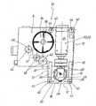
- the figure shows a design of the embossing device 10, which is provided for embossing a decorative layer of a strip-shaped embossing foil 12 on a small radius possessing corner of a surface element, not shown.
- the embossing device 10 has a base frame 14, on which a turret 16 is gradually rotatable about an axis 18.
- the turret 18 is provided on a linear drive device 20.
- the linear drive device 20 is formed by a piston-cylinder device 22.
- the cylinder 24 of the piston-cylinder device 22 is fixed to the base frame 14.
- the turret 16 is connected to the piston of the piston-cylinder device 22.
- the turret 16 With the aid of the linear drive device 22, the turret 16 between an embossing position and an inactive positive back and forth adjustable.
- the turret 16 has at its periphery 26 a number of elastic stamp elements 28.
- the stamp members 28 are made of silicone rubber and are arranged at the periphery 26 of the turret 16 evenly spaced.
- the turret 16 is associated with a heater 30 for the stamp elements 28.
- the heater 30 is preferably provided in the center of the turret 16. It is particularly advantageous here if the heating device 30 is provided in the axis 18 of the turret.
- a stamping foil supply roll 34 is rotatably mounted on a bearing axis 36.
- film feed rollers 38 and guide rollers 40 are rotatably mounted on corresponding bearing axles 42, 44.
- a take-up roller 46 for the carrier strip of the embossing foil 12 is also rotatably mounted on an associated bearing shaft 48.
Landscapes
- Shaping Of Tube Ends By Bending Or Straightening (AREA)
Abstract
Description
- Die Erfindung betrifft eine Vorrichtung zum Prägen einer Dekorlage einer streifenförmigen Prägefolie auf eine, einen kleinen Radius besitzende Ecke eines Flächenelementes.
- Eine Vorrichtung zum Prägen einer Dekorlage einer streifenförmigen Prägefolie auf die, ein Flächenelement begrenzenden Schmalseiten des Flächenelementes ist beispielsweise aus der
DE 102 16 139 C1 bekannt. Mit dieser bekannten Prägevorrichtung ist es mit großen Taktgeschwindigkeiten, d.h. hohen Taktzahlen, möglich, Flächenelemente an ihren Schmalseiten mit der Dekorlage einer streifenförmigen Prägefolie zu beprägen. Ist das jeweilige Flächenelement jedoch an seinen Ecken mit einen kleinen Radius besitzenden Abrundungen ausgebildet, so werden die entsprechenden Dekorlagenabschnitte an den besagten Ecken bislang beispielsweise mit einem manuell zu handhabenden Werkzeug an den abgerundeten Ecken fixiert. Diese manuelle Arbeitsweise ist jedoch nur mit niedrigen Taktgeschwindigkeiten bzw. Taktzahlen möglich, so dass die Produktivität entsprechende Wünsche offen lässt. Die Abrundungen können z.B. einen Radius von 2 mm bis 5 mm besitzen, wobei es sich versteht, dass die entsprechenden Probleme auch bei Radien mit anderen Dimensionen gegeben sind. - Zum Beprägen abgerundeter Ecken von Flächenelementen ist beispielsweise auch eine Hubprägung anwendbar, wie sie beispielsweise mit einer Prägemaschine des Typs PE500/KTF "Touchwood" durchführbar ist. Mit einer derartigen Prägemaschine sind einen kleinen Radius aufweisende Ecken eines Flächenelementes jedoch nur mit mäßigen Taktgeschwindigkeiten beprägbar.
- Desgleichen ist es möglich, an dem zu beprägenden Flächenelement Stiftelemente aus einem Kunststoffmaterial peripher abzurollen, wobei das zu beprägende Flächenelement und die Stiftelemente während des Dekoriervorgangs in Bezug zueinander eine Relativbewegung ausführen. Mit einem solchen bekannten Doppelprägekopf sind im Vergleich zu einer Hubprägung zwar höhere Prägegeschwindigkeiten erreichbar; auch diese höhere Geschwindigkeit lässt jedoch im Vergleich zu einer Prägevorrichtung gemäß der eingangs erwähnten
DE 102 16 139 C1 , zum Prägen von Schmalseiten von Flächenelementen, noch Wünsche offen. Das resultiert beispielsweise aus den Isolationseigenschaften der Kunststoffstifte des Doppelprägekopfes, da die Wärme vom Stempelinneren an die Stempeloberfläche transportiert werden muss, was relativ viel Zeit benötigt. Dementsprechend niedrig ist die Durchsatzleistung an zu beprägenden Flächenelementen pro Zeiteinheit. - In Kenntnis dieser Gegebenheiten liegt der Erfindung die Aufgabe zugrunde, eine Prägevorrichtung der eingangs genannten Art zu schaffen, mit der es mit hoher Produktivität, d.h. mit großer Prägegeschwindigkeit und hohen Taktzahlen, möglich ist, einen kleinen Radius besitzende Ecken eines Flächenelementes mit einer Dekorlage einer streifenförmigen Prägefolie zu beprägen.
- Diese Aufgabe wird bei einer Vorrichtung der eingangs genannten Art erfindungsgemäß gelöst durch einen schrittweise um eine Achse drehbaren Revolverkopf, der an einer linearen Antriebseinrichtung zwischen einer Prägeposition und einer Inaktivposition hin und her verstellbar vorgesehen ist, und der an seinem Umfang eine Anzahl elastische. Stempelelemente aufweist, wobei dem Revolverkopf eine Heizeinrichtung für die Stempelelemente zugeordnet ist.
- Durch die erfindungsgemäße Ausbildung der Prägevorrichtung wird für eine schnelle Wärmezufuhr zu den elastischen Stempelelementen gesorgt. Es ist jederzeit ein frisch aufgeheiztes elastisches Stempelelement im Prägeeinsatz, so dass eine entsprechend hohe Taktgeschwindigkeit erreicht wird. Als "elastisch" wird ein Stempelelement bezeichnet, wenn die Oberfläche des Materials, aus welchem das Stempelelement gebildet ist, eine Härte im Bereich von 45° Shore bis 95° Shore, bevorzugt im Bereich von 60° Shore bis 80° Shore, insbesondere von etwa 70° Shore, aufweist.
- Dabei ist die Elastizität der Oberfläche eines Stempelelements auf den Radius der Ecke des Flächenelements abzustimmen, welche beprägt werden soll. So sollen die elastischen- Stempelelemente am Umfang des Revolverkopfes im Bereich des Radius der Ecke des Flächenelements derart angedrückt werden können, dass sich jedes Stempelelement dem Radius anpasst und so zu einer optimalen Übertragung der Dekorlage auf die Ecke des Flächenelements führt. Je kleiner der Radius ausgebildet ist, desto elastischer ist demnach ein Stempelelement auszubilden.
- Bei der erfindungsgemäßen Prägevorrichtung kann die Linearantriebseinrichtung von einer Kolben-Zylindereinrichtung gebildet sein.
- Die Stempelelemente können zumindest oberflächlich Silikongummi aufweisen, zweckmäßig kann es sein, wenn die Stempelelemente aus Silikongummi bestehen.
- Die Heizeinrichtung für die am Revolverkopf vorgesehenen elastischen Stempelelemente ist vorzugsweise im Zentrum des Revolverkopfes vorgesehen. Zu diesem Zwecke ist die Heizeinrichtung vorzugsweise in der Achse des Revolverkopfes vorgesehen. Desgleichen ist es möglich, dass die Heizeinrichtung Heizstrahler aufweist, zwischen welchen der Revolverkopf vorgesehen ist, wobei die Heizstrahler vorzugsweise in einer zur Achse des Revolverkopfes senkrecht orientierten Ebene angeordnet sind.
- Der Revolverkopf mit der zugehörigen Linearantriebseinrichtung und die Heizeinrichtung sind zweckmäßigerweise an einem Grundgestell vorgesehen, an dem eine Prägefolien-Vorratsrolle, Folienvorschub- und -umlenkrollen und eine Aufwickelrolle an zugehörigen Lagerachsen gelagert sind. Die Lagerachsen für die Prägefolien-Vorratsrolle, die Folienvorschub- und -umlenkrollen und die Aufwickelrolle sind zur Achse des Revolverkopfes vorzugsweise parallel orientiert.
- Ein optimaler Einsatz der erfindungsgemäßen Vorrichtung ist in der Weise realisierbar, dass eine der Anzahl abgerundeter Ecken des jeweiligen Flächenelementes entsprechende Anzahl Grundgestelle vorgesehen sind, wobei die Revolverköpfe simultan zwischen der Prägeposition und der Inaktivposition hin und her verstellbar sind.
- Mit der erfindungsgemäßen Prägevorrichtung ist es hoch produktiv möglich, die einen kleinen Radius von z.B. 2 bis 5 mm besitzenden abgerundeten Ecken eines Flächenelementes mit einer streifenförmigen Prägefolie zu beprägen, wobei die entsprechenden Taktgeschwindigkeiten an die Taktgeschwindigkeiten der Prägevorrichtung angepasst sind, mit welcher die Schmalseiten des Flächenelementes mit der streifenförmigen Prägefolie beprägt werden. Die besagten Schmalflächen können dabei geradlinig oder gebogen, gewellt oder beliebig anders gestaltet sein. Die einen kleinen Radius besitzenden Ecken des jeweiligen Flächenelementes können wie seine Schmalseiten ebenflächig oder konkav oder konvex gewölbt gestaltet sein.
- Weitere Einzelheiten, Merkmale und Vorteile ergeben sich aus der nachfolgenden Beschreibung eines in der Zeichnung schematisch in einer Seitenansicht verdeutlichten Ausführungsbeispieles der erfindungsgemäßen Prägevorrichtung.
- Die Figur zeigt eine Ausbildung der Prägevorrichtung 10, die zum Prägen einer Dekorlage einer streifenförmigen Prägefolie 12 auf eine einen kleinen Radius besitzenden Ecke eines nicht dargestellten Flächenelementes vorgesehen ist. Die Prägevorrichtung 10 weist ein Grundgestell 14 auf, an dem ein Revolverkopf 16 schrittweise um eine Achse 18 drehbar ist. Der Revolverkopf 18 ist an einer Linearantriebseinrichtung 20 vorgesehen. Die Linearantriebseinrichtung 20 ist von einer Kolben-Zylindereinrichtung 22 gebildet. Der Zylinder 24 der Kolben-Zylindereinrichtung 22 ist am Grundgestell 14 befestigt. Der Revolverkopf 16 ist mit dem Kolben der Kolben-Zylindereinrichtung 22 verbunden.
- Mit Hilfe der Linearantriebseinrichtung 22 ist der Revolverkopf 16 zwischen einer Prägeposition und einer Inaktivpositiv hin und her verstellbar.
- Der Revolverkopf 16 weist an seinem Umfang 26 eine Anzahl elastische Stempelelemente 28 auf. Die Stempelelemente 28 bestehen aus Silikongummi und sind am Umfang 26 des Revolverkopfes 16 gleichmäßig beabstandet angeordnet.
- Dem Revolverkopf 16 ist eine Heizeinrichtung 30 für die Stempelelemente 28 zugeordnet. Die Heizeinrichtung 30 ist vorzugsweise im Zentrum des Revolverkopfes 16 vorgesehen. Besonders vorteilhaft ist es hierbei, wenn die Heizeinrichtung 30 in der Achse 18 des Revolverkopfes vorgesehen ist.
- Mit der Bezugsziffer 32 sind in der Zeichnungsfigur Folienumlenkrollenbügel bezeichnet:
- Am Grundgestell 14 der Prägevorrichtung 10 ist eine Prägefolien-Vorratsrolle 34 an einer Lagerachse 36 drehbar gelagert. Am Grundgestell 14 sind außerdem Folienvorschubrollen 38 und Umlenkrollen 40 an zugehörigen Lagerachsen 42, 44 drehbar gelagert. Am Grundgestell 14 ist außerdem eine Aufwickelrolle 46 für den Trägerstreifen der Prägefolie 12 an einer zugehörigen Lagerachse 48 drehbar gelagert.
Claims (10)
- Vorrichtung zum Prägen einer Dekorlage einer streifenförmigen Prägefolie (12) auf eine einen kleinen Radius besitzende Ecke eines Flächenelementes,
gekennzeichnet durch
einen schrittweise um eine Achse (18) drehbaren Revolverkopf (16), der an einer Linearantriebseinrichtung (20) zwischen einer Prägeposition und einer Inaktivposition hin und her verstellbar vorgesehen ist, und der an seinem Umfang (26) eine Anzahl elastische Stempelelemente (28) aufweist, wobei den Stempelelementen (28) des Revolverkopfes (16) eine Heizeinrichtung (30) für die Stempelelemente (28) zugeordnet ist. - Vorrichtung nach Anspruch 1,
dadurch gekennzeichnet,
dass die Linearantriebseinrichtung (20) von einer Kolben-Zylindereinrichtung (22) gebildet ist. - Vorrichtung nach Anspruch 1,
dadurch gekennzeichnet,
dass die Stempelelemente (28) zumindest oberflächlich Silikongummi aufweisen. - Vorrichtung nach Anspruch 1,
dadurch gekennzeichnet,
dass die Stempelelemente (28) aus Silikongummi bestehen. - Vorrichtung nach Anspruch 1,
dadurch gekennzeichnet,
dass die Heizeinrichtung (30) im Zentrum des Revolverkopfes (16) vorgesehen ist. - Vorrichtung nach Anspruch 5,
dadurch gekennzeichnet,
dass die Heizeinrichtung (30) in der Achse (18) des Revolverkopfes (16) vorgesehen ist. - Vorrichtung nach Anspruch 1,
dadurch gekennzeichnet,
dass die Heizeinrichtung (30) Heizstrahler aufweist, zwischen welchen der Revolverkopf (16) vorgesehen ist. - Vorrichtung nach einem der Ansprüche 1 bis 7,
dadurch gekennzeichnet,
dass der Revolverkopf (16) mit der zugehörigen Linearantriebseinrichtung (20) und die Heizeinrichtung (30) an einem Grundgestell (14) vorgesehen sind, an dem eine Prägefolien-Vorratsrolle (34), Folienvorschub- und - umlenkrollen (38, 40) und eine Aufwickelrolle (46) an zugehörigen Lagerachsen (36, 42, 44, 48) gelagert sind. - Vorrichtung nach Anspruch 8,
dadurch gekennzeichnet,
dass die Lagerachsen (36, 42, 44, 48) für die Prägefolien-Vorratsrolle (34), die Folienvorschub- und -umlenkrollen (38, 40) und die Aufwickelrolle (46) zur Achse (18) des Revolverkopfes (16) parallel orientiert sind. - Vorrichtung nach Anspruch 8,
dadurch gekennzeichnet,
dass eine der Anzahl Ecken des jeweiligen zu beprägenden Flächenelementes entsprechende Anzahl Grundgestelle (14) vorgesehen sind, wobei die Revolverköpfe (16) simultan zwischen der Prägeposition und der Inaktivposition hin und her verstellbar sind.
Priority Applications (1)
| Application Number | Priority Date | Filing Date | Title |
|---|---|---|---|
| PL07022908T PL1927479T3 (pl) | 2006-11-30 | 2007-11-27 | Urządzenie do tłoczenia z ogrzewaną głowicą rewolwerową i sposób tłoczenia |
Applications Claiming Priority (1)
| Application Number | Priority Date | Filing Date | Title |
|---|---|---|---|
| DE102006056701A DE102006056701B4 (de) | 2006-11-30 | 2006-11-30 | Prägevorrichtung |
Publications (3)
| Publication Number | Publication Date |
|---|---|
| EP1927479A2 true EP1927479A2 (de) | 2008-06-04 |
| EP1927479A3 EP1927479A3 (de) | 2008-09-17 |
| EP1927479B1 EP1927479B1 (de) | 2013-01-30 |
Family
ID=39047559
Family Applications (1)
| Application Number | Title | Priority Date | Filing Date |
|---|---|---|---|
| EP07022908A Active EP1927479B1 (de) | 2006-11-30 | 2007-11-27 | Prägevorrichtung mit beheizbarem Revolverkopf und Prägeverfahren |
Country Status (5)
| Country | Link |
|---|---|
| US (1) | US7913619B2 (de) |
| EP (1) | EP1927479B1 (de) |
| CA (1) | CA2612359C (de) |
| DE (1) | DE102006056701B4 (de) |
| PL (1) | PL1927479T3 (de) |
Families Citing this family (1)
| Publication number | Priority date | Publication date | Assignee | Title |
|---|---|---|---|---|
| WO2023076522A1 (en) * | 2021-10-27 | 2023-05-04 | Footprint International, LLC | Marking systems and methods for fiber-based products |
Citations (4)
| Publication number | Priority date | Publication date | Assignee | Title |
|---|---|---|---|---|
| DE1161568B (de) | 1958-04-03 | 1964-01-23 | Dr Elmar Messerschmitt | Praegestempel |
| DE3531898A1 (de) | 1984-09-08 | 1986-03-27 | Fritz Wagner, Maschinenfabrik Gmbh & Co Kg, 6781 Schweix | Initialenpraegemaschine |
| EP0437720A1 (de) | 1989-12-15 | 1991-07-24 | Leonhard Kurz Gmbh & Co. | Verfahren zum Übertragen eines Dekors von einer Prägefolie auf ein ebenflächiges Substrat und Vorrichtung zur Durchführung des Verfahrens |
| DE10216139C1 (de) | 2002-04-12 | 2003-12-11 | Kurz Leonhard Fa | Prägevorrichtung |
Family Cites Families (16)
| Publication number | Priority date | Publication date | Assignee | Title |
|---|---|---|---|---|
| US2961950A (en) * | 1957-04-15 | 1960-11-29 | Lewis A Kingsley | Type holding head for tape marking machine |
| US2996000A (en) * | 1958-08-25 | 1961-08-15 | Lewis A Kingsley | Air-operated wire and tube marking machine |
| US3483063A (en) * | 1966-11-01 | 1969-12-09 | Dennison Mfg Co | Apparatus for applying indicia to articles |
| US3975226A (en) * | 1975-05-12 | 1976-08-17 | Automatic Industrial Machines, Inc. | Apparatus for dry printing on contoured workpieces |
| US4175993A (en) * | 1977-11-09 | 1979-11-27 | Ethyl Development Corporation | Article decorating machine and method |
| US4327635A (en) * | 1980-05-29 | 1982-05-04 | United States Steel Corporation | Indexable marking wheel |
| US4453468A (en) * | 1982-12-29 | 1984-06-12 | Shenoha James L | Heat conducting magnetic type holder for imprinters |
| BR8807319A (pt) * | 1987-10-26 | 1990-03-27 | Dennison Mfg Co | Processo de decoracao de banda |
| US5115737A (en) | 1990-04-16 | 1992-05-26 | Philip Morris Incorporated | Hot rotary stamper apparatus and methods for metal leaf stamping |
| DE4121766A1 (de) * | 1991-07-01 | 1993-01-07 | Kurz Leonhard Fa | Vorrichtung zum uebertragen eines dekors von einer praegefolie auf eine materialbahn |
| DE9416290U1 (de) | 1994-10-12 | 1994-12-01 | Dziersk, Wilfried, 30900 Wedemark | Heißprägemaschine zum Einfärben von geprägten Schildern, insbesondere von Kraftfahrzeug-Kennzeichenschildern |
| DE29620889U1 (de) * | 1996-12-02 | 1997-03-13 | LUPRA D. Kehret KG lufthydraulische Präzisionsapparate, 77694 Kehl | Vorrichtung zum Kennzeichnen von Gegenständen |
| DE10037643A1 (de) * | 2000-07-31 | 2002-02-21 | Ms Praegesysteme Gmb | Prägemaschine für Prägefolien |
| DE10352700B3 (de) | 2003-11-12 | 2005-01-20 | Leonhard Kurz Gmbh & Co. Kg | Prägestation für eine Prägevorrichtung |
| DE202004003746U1 (de) | 2004-03-10 | 2004-05-19 | m-tech AG | Vorrichtung zum Übertragen von Material von einer Heissprägefolie auf ein Druckgut |
| DE102004014373B4 (de) | 2004-03-24 | 2006-09-21 | Hinderer + Mühlich Kg | Prägestempel zum Heiss- oder Kaltprägen |
-
2006
- 2006-11-30 DE DE102006056701A patent/DE102006056701B4/de not_active Expired - Fee Related
-
2007
- 2007-11-26 CA CA2612359A patent/CA2612359C/en active Active
- 2007-11-27 PL PL07022908T patent/PL1927479T3/pl unknown
- 2007-11-27 EP EP07022908A patent/EP1927479B1/de active Active
- 2007-11-27 US US11/986,868 patent/US7913619B2/en not_active Expired - Fee Related
Patent Citations (4)
| Publication number | Priority date | Publication date | Assignee | Title |
|---|---|---|---|---|
| DE1161568B (de) | 1958-04-03 | 1964-01-23 | Dr Elmar Messerschmitt | Praegestempel |
| DE3531898A1 (de) | 1984-09-08 | 1986-03-27 | Fritz Wagner, Maschinenfabrik Gmbh & Co Kg, 6781 Schweix | Initialenpraegemaschine |
| EP0437720A1 (de) | 1989-12-15 | 1991-07-24 | Leonhard Kurz Gmbh & Co. | Verfahren zum Übertragen eines Dekors von einer Prägefolie auf ein ebenflächiges Substrat und Vorrichtung zur Durchführung des Verfahrens |
| DE10216139C1 (de) | 2002-04-12 | 2003-12-11 | Kurz Leonhard Fa | Prägevorrichtung |
Also Published As
| Publication number | Publication date |
|---|---|
| EP1927479A3 (de) | 2008-09-17 |
| DE102006056701B4 (de) | 2008-08-28 |
| EP1927479B1 (de) | 2013-01-30 |
| CA2612359A1 (en) | 2008-05-30 |
| CA2612359C (en) | 2015-05-19 |
| US20080173192A1 (en) | 2008-07-24 |
| US7913619B2 (en) | 2011-03-29 |
| DE102006056701A1 (de) | 2008-06-05 |
| PL1927479T3 (pl) | 2013-06-28 |
Similar Documents
| Publication | Publication Date | Title |
|---|---|---|
| DE3829297C2 (de) | ||
| WO2014037044A1 (de) | Strukturstempel, vorrichtung und verfahren zum prägen | |
| EP2722194B1 (de) | Werkzeug zum Bearbeiten von Werkstücken, insbesondere Blechen | |
| DE4025712C1 (de) | ||
| DE19614740A1 (de) | Verfahren und Vorrichtung zum Bedrucken von selbsttragenden Einzelobjekten | |
| DE102016000662A1 (de) | Vorrichtung zum Heißfolienprägen | |
| EP1927479A2 (de) | Prägevorrichtung mit beheizbarem Revolverkopf | |
| EP0392047B1 (de) | Verfahren und Vorrichtung zum Heissverformen einer Kunstharz-Schichtpressstoffplatte | |
| EP1872880A1 (de) | Verfahren und Vorrichtung zum Prägen eines Trommelmantels | |
| DE19706295C2 (de) | Verfahren zum Drucken von Mustern | |
| DE102015220714A1 (de) | Druckmaschine zum Bedrucken von Behältern | |
| DE69523941T2 (de) | Verfahren und vorrichtung zum formen von blechmaterial | |
| DE102014218168B4 (de) | Rotationsdruckverfahren und Tampondruckmaschine | |
| DE10159661C1 (de) | Heißprägemaschine mit einer Prägestation | |
| EP3235653A1 (de) | Vorwärmstation für ein verformungswerkzeug zum verformen von buchdecken | |
| DE2341334C3 (de) | Einrichtung zum Prägedrucken von Zylindermantelflächen | |
| DE2108256C3 (de) | Vorrichtung zum Kennzeichnen von Etiketten, insbesondere für Etikettiermaschinen | |
| DE4433054C1 (de) | Verfahren und Vorrichtung zum Bedrucken eines Substrates durch Heißprägen | |
| DE3531898A1 (de) | Initialenpraegemaschine | |
| DE102009026190A1 (de) | Vorrichtung zum Prägen variabler Oberflächenstrukturen in ebene Flächengebilden mit Hilfe walzenförmiger Prägestempel | |
| DE3020180A1 (de) | Verfahren zur herstellung eines reliefs auf der glasur einer fliese und vorrichtung zur durchfuehrung des verfahrens | |
| DE69626189T2 (de) | Vorrichtung zur Herstellung von Kunststofflaminaten | |
| DE2219913A1 (de) | Einrichtung mit zwei formsaetzen zur praegung und aufbringung von folie auf ein blatt | |
| CH658416A5 (de) | Vorrichtung zum schleifenfoermigen biegen eines fortlaufenden drahtes. | |
| WO2024068320A1 (de) | Vorrichtung zum härten von blechbauteilen |
Legal Events
| Date | Code | Title | Description |
|---|---|---|---|
| PUAI | Public reference made under article 153(3) epc to a published international application that has entered the european phase |
Free format text: ORIGINAL CODE: 0009012 |
|
| AK | Designated contracting states |
Kind code of ref document: A2 Designated state(s): AT BE BG CH CY CZ DE DK EE ES FI FR GB GR HU IE IS IT LI LT LU LV MC MT NL PL PT RO SE SI SK TR |
|
| AX | Request for extension of the european patent |
Extension state: AL BA HR MK RS |
|
| PUAL | Search report despatched |
Free format text: ORIGINAL CODE: 0009013 |
|
| AK | Designated contracting states |
Kind code of ref document: A3 Designated state(s): AT BE BG CH CY CZ DE DK EE ES FI FR GB GR HU IE IS IT LI LT LU LV MC MT NL PL PT RO SE SI SK TR |
|
| AX | Request for extension of the european patent |
Extension state: AL BA HR MK RS |
|
| 17P | Request for examination filed |
Effective date: 20090313 |
|
| AKX | Designation fees paid |
Designated state(s): AT BE BG CH CY CZ DE DK EE ES FI FR GB GR HU IE IS IT LI LT LU LV MC MT NL PL PT RO SE SI SK TR |
|
| 17Q | First examination report despatched |
Effective date: 20101102 |
|
| R17C | First examination report despatched (corrected) |
Effective date: 20101202 |
|
| GRAP | Despatch of communication of intention to grant a patent |
Free format text: ORIGINAL CODE: EPIDOSNIGR1 |
|
| GRAS | Grant fee paid |
Free format text: ORIGINAL CODE: EPIDOSNIGR3 |
|
| GRAA | (expected) grant |
Free format text: ORIGINAL CODE: 0009210 |
|
| AK | Designated contracting states |
Kind code of ref document: B1 Designated state(s): AT BE BG CH CY CZ DE DK EE ES FI FR GB GR HU IE IS IT LI LT LU LV MC MT NL PL PT RO SE SI SK TR |
|
| REG | Reference to a national code |
Ref country code: GB Ref legal event code: FG4D Free format text: NOT ENGLISH |
|
| REG | Reference to a national code |
Ref country code: CH Ref legal event code: EP |
|
| REG | Reference to a national code |
Ref country code: AT Ref legal event code: REF Ref document number: 595642 Country of ref document: AT Kind code of ref document: T Effective date: 20130215 Ref country code: CH Ref legal event code: EP |
|
| REG | Reference to a national code |
Ref country code: IE Ref legal event code: FG4D Free format text: LANGUAGE OF EP DOCUMENT: GERMAN |
|
| REG | Reference to a national code |
Ref country code: CH Ref legal event code: NV Representative=s name: FIAMMENGHI-FIAMMENGHI, CH |
|
| REG | Reference to a national code |
Ref country code: DE Ref legal event code: R096 Ref document number: 502007011273 Country of ref document: DE Effective date: 20130321 |
|
| REG | Reference to a national code |
Ref country code: LT Ref legal event code: MG4D |
|
| REG | Reference to a national code |
Ref country code: PL Ref legal event code: T3 |
|
| REG | Reference to a national code |
Ref country code: NL Ref legal event code: VDEP Effective date: 20130130 |
|
| PG25 | Lapsed in a contracting state [announced via postgrant information from national office to epo] |
Ref country code: SE Free format text: LAPSE BECAUSE OF FAILURE TO SUBMIT A TRANSLATION OF THE DESCRIPTION OR TO PAY THE FEE WITHIN THE PRESCRIBED TIME-LIMIT Effective date: 20130130 Ref country code: IS Free format text: LAPSE BECAUSE OF FAILURE TO SUBMIT A TRANSLATION OF THE DESCRIPTION OR TO PAY THE FEE WITHIN THE PRESCRIBED TIME-LIMIT Effective date: 20130530 Ref country code: BG Free format text: LAPSE BECAUSE OF FAILURE TO SUBMIT A TRANSLATION OF THE DESCRIPTION OR TO PAY THE FEE WITHIN THE PRESCRIBED TIME-LIMIT Effective date: 20130430 Ref country code: CY Free format text: LAPSE BECAUSE OF FAILURE TO SUBMIT A TRANSLATION OF THE DESCRIPTION OR TO PAY THE FEE WITHIN THE PRESCRIBED TIME-LIMIT Effective date: 20130130 Ref country code: LT Free format text: LAPSE BECAUSE OF FAILURE TO SUBMIT A TRANSLATION OF THE DESCRIPTION OR TO PAY THE FEE WITHIN THE PRESCRIBED TIME-LIMIT Effective date: 20130130 Ref country code: ES Free format text: LAPSE BECAUSE OF FAILURE TO SUBMIT A TRANSLATION OF THE DESCRIPTION OR TO PAY THE FEE WITHIN THE PRESCRIBED TIME-LIMIT Effective date: 20130511 |
|
| PG25 | Lapsed in a contracting state [announced via postgrant information from national office to epo] |
Ref country code: SI Free format text: LAPSE BECAUSE OF FAILURE TO SUBMIT A TRANSLATION OF THE DESCRIPTION OR TO PAY THE FEE WITHIN THE PRESCRIBED TIME-LIMIT Effective date: 20130130 Ref country code: LV Free format text: LAPSE BECAUSE OF FAILURE TO SUBMIT A TRANSLATION OF THE DESCRIPTION OR TO PAY THE FEE WITHIN THE PRESCRIBED TIME-LIMIT Effective date: 20130130 Ref country code: FI Free format text: LAPSE BECAUSE OF FAILURE TO SUBMIT A TRANSLATION OF THE DESCRIPTION OR TO PAY THE FEE WITHIN THE PRESCRIBED TIME-LIMIT Effective date: 20130130 Ref country code: PT Free format text: LAPSE BECAUSE OF FAILURE TO SUBMIT A TRANSLATION OF THE DESCRIPTION OR TO PAY THE FEE WITHIN THE PRESCRIBED TIME-LIMIT Effective date: 20130530 Ref country code: NL Free format text: LAPSE BECAUSE OF FAILURE TO SUBMIT A TRANSLATION OF THE DESCRIPTION OR TO PAY THE FEE WITHIN THE PRESCRIBED TIME-LIMIT Effective date: 20130130 Ref country code: GR Free format text: LAPSE BECAUSE OF FAILURE TO SUBMIT A TRANSLATION OF THE DESCRIPTION OR TO PAY THE FEE WITHIN THE PRESCRIBED TIME-LIMIT Effective date: 20130501 |
|
| PG25 | Lapsed in a contracting state [announced via postgrant information from national office to epo] |
Ref country code: DK Free format text: LAPSE BECAUSE OF FAILURE TO SUBMIT A TRANSLATION OF THE DESCRIPTION OR TO PAY THE FEE WITHIN THE PRESCRIBED TIME-LIMIT Effective date: 20130130 Ref country code: RO Free format text: LAPSE BECAUSE OF FAILURE TO SUBMIT A TRANSLATION OF THE DESCRIPTION OR TO PAY THE FEE WITHIN THE PRESCRIBED TIME-LIMIT Effective date: 20130130 Ref country code: EE Free format text: LAPSE BECAUSE OF FAILURE TO SUBMIT A TRANSLATION OF THE DESCRIPTION OR TO PAY THE FEE WITHIN THE PRESCRIBED TIME-LIMIT Effective date: 20130130 Ref country code: SK Free format text: LAPSE BECAUSE OF FAILURE TO SUBMIT A TRANSLATION OF THE DESCRIPTION OR TO PAY THE FEE WITHIN THE PRESCRIBED TIME-LIMIT Effective date: 20130130 Ref country code: CZ Free format text: LAPSE BECAUSE OF FAILURE TO SUBMIT A TRANSLATION OF THE DESCRIPTION OR TO PAY THE FEE WITHIN THE PRESCRIBED TIME-LIMIT Effective date: 20130130 |
|
| PLBE | No opposition filed within time limit |
Free format text: ORIGINAL CODE: 0009261 |
|
| STAA | Information on the status of an ep patent application or granted ep patent |
Free format text: STATUS: NO OPPOSITION FILED WITHIN TIME LIMIT |
|
| 26N | No opposition filed |
Effective date: 20131031 |
|
| REG | Reference to a national code |
Ref country code: DE Ref legal event code: R097 Ref document number: 502007011273 Country of ref document: DE Effective date: 20131031 |
|
| BERE | Be: lapsed |
Owner name: LEONHARD KURZ STIFTUNG & CO. K.G. Effective date: 20131130 |
|
| GBPC | Gb: european patent ceased through non-payment of renewal fee |
Effective date: 20131127 |
|
| PG25 | Lapsed in a contracting state [announced via postgrant information from national office to epo] |
Ref country code: MC Free format text: LAPSE BECAUSE OF FAILURE TO SUBMIT A TRANSLATION OF THE DESCRIPTION OR TO PAY THE FEE WITHIN THE PRESCRIBED TIME-LIMIT Effective date: 20130130 |
|
| REG | Reference to a national code |
Ref country code: IE Ref legal event code: MM4A |
|
| PG25 | Lapsed in a contracting state [announced via postgrant information from national office to epo] |
Ref country code: BE Free format text: LAPSE BECAUSE OF NON-PAYMENT OF DUE FEES Effective date: 20131130 |
|
| PG25 | Lapsed in a contracting state [announced via postgrant information from national office to epo] |
Ref country code: IE Free format text: LAPSE BECAUSE OF NON-PAYMENT OF DUE FEES Effective date: 20131127 |
|
| PG25 | Lapsed in a contracting state [announced via postgrant information from national office to epo] |
Ref country code: GB Free format text: LAPSE BECAUSE OF NON-PAYMENT OF DUE FEES Effective date: 20131127 |
|
| REG | Reference to a national code |
Ref country code: AT Ref legal event code: MM01 Ref document number: 595642 Country of ref document: AT Kind code of ref document: T Effective date: 20131127 |
|
| PG25 | Lapsed in a contracting state [announced via postgrant information from national office to epo] |
Ref country code: AT Free format text: LAPSE BECAUSE OF NON-PAYMENT OF DUE FEES Effective date: 20131127 |
|
| PG25 | Lapsed in a contracting state [announced via postgrant information from national office to epo] |
Ref country code: HU Free format text: LAPSE BECAUSE OF FAILURE TO SUBMIT A TRANSLATION OF THE DESCRIPTION OR TO PAY THE FEE WITHIN THE PRESCRIBED TIME-LIMIT; INVALID AB INITIO Effective date: 20071127 Ref country code: LU Free format text: LAPSE BECAUSE OF NON-PAYMENT OF DUE FEES Effective date: 20131127 |
|
| PG25 | Lapsed in a contracting state [announced via postgrant information from national office to epo] |
Ref country code: MT Free format text: LAPSE BECAUSE OF FAILURE TO SUBMIT A TRANSLATION OF THE DESCRIPTION OR TO PAY THE FEE WITHIN THE PRESCRIBED TIME-LIMIT Effective date: 20130130 |
|
| REG | Reference to a national code |
Ref country code: FR Ref legal event code: PLFP Year of fee payment: 9 |
|
| REG | Reference to a national code |
Ref country code: FR Ref legal event code: PLFP Year of fee payment: 10 |
|
| REG | Reference to a national code |
Ref country code: FR Ref legal event code: PLFP Year of fee payment: 11 |
|
| PGFP | Annual fee paid to national office [announced via postgrant information from national office to epo] |
Ref country code: PL Payment date: 20240910 Year of fee payment: 18 |
|
| PGFP | Annual fee paid to national office [announced via postgrant information from national office to epo] |
Ref country code: DE Payment date: 20241112 Year of fee payment: 18 |
|
| PGFP | Annual fee paid to national office [announced via postgrant information from national office to epo] |
Ref country code: FR Payment date: 20241128 Year of fee payment: 18 |
|
| PGFP | Annual fee paid to national office [announced via postgrant information from national office to epo] |
Ref country code: IT Payment date: 20241129 Year of fee payment: 18 |
|
| PGFP | Annual fee paid to national office [announced via postgrant information from national office to epo] |
Ref country code: CH Payment date: 20241201 Year of fee payment: 18 |
|
| PGFP | Annual fee paid to national office [announced via postgrant information from national office to epo] |
Ref country code: TR Payment date: 20241115 Year of fee payment: 18 |