EP1925805A1 - Canal de refroidissement variable pour un piston - Google Patents
Canal de refroidissement variable pour un piston Download PDFInfo
- Publication number
- EP1925805A1 EP1925805A1 EP07021851A EP07021851A EP1925805A1 EP 1925805 A1 EP1925805 A1 EP 1925805A1 EP 07021851 A EP07021851 A EP 07021851A EP 07021851 A EP07021851 A EP 07021851A EP 1925805 A1 EP1925805 A1 EP 1925805A1
- Authority
- EP
- European Patent Office
- Prior art keywords
- cooling channel
- piston
- coolant
- flow
- piston according
- Prior art date
- Legal status (The legal status is an assumption and is not a legal conclusion. Google has not performed a legal analysis and makes no representation as to the accuracy of the status listed.)
- Withdrawn
Links
Images


Classifications
-
- F—MECHANICAL ENGINEERING; LIGHTING; HEATING; WEAPONS; BLASTING
- F02—COMBUSTION ENGINES; HOT-GAS OR COMBUSTION-PRODUCT ENGINE PLANTS
- F02F—CYLINDERS, PISTONS OR CASINGS, FOR COMBUSTION ENGINES; ARRANGEMENTS OF SEALINGS IN COMBUSTION ENGINES
- F02F3/00—Pistons
- F02F3/16—Pistons having cooling means
- F02F3/20—Pistons having cooling means the means being a fluid flowing through or along piston
- F02F3/22—Pistons having cooling means the means being a fluid flowing through or along piston the fluid being liquid
-
- B—PERFORMING OPERATIONS; TRANSPORTING
- B22—CASTING; POWDER METALLURGY
- B22C—FOUNDRY MOULDING
- B22C9/00—Moulds or cores; Moulding processes
- B22C9/10—Cores; Manufacture or installation of cores
- B22C9/105—Salt cores
-
- F—MECHANICAL ENGINEERING; LIGHTING; HEATING; WEAPONS; BLASTING
- F01—MACHINES OR ENGINES IN GENERAL; ENGINE PLANTS IN GENERAL; STEAM ENGINES
- F01P—COOLING OF MACHINES OR ENGINES IN GENERAL; COOLING OF INTERNAL-COMBUSTION ENGINES
- F01P3/00—Liquid cooling
- F01P3/06—Arrangements for cooling pistons
- F01P3/10—Cooling by flow of coolant through pistons
Definitions
- the invention relates to a liquid-cooled piston of an internal combustion engine, in which a radially encircling, a coolant leading cooling channel is integrated.
- the coolant circulating in the cooling channel enters via at least one inflow opening and via at least one outflow opening.
- the cooling channel includes measures for influencing a coolant flow.
- Pistons for internal combustion engines are exposed to high temperatures.
- an annular cooling channel is introduced, which is acted upon by the coolant, in particular the lubricating oil of the internal combustion engine.
- the circulating in the cooling channel coolant causes heat removal from the piston, which in particular the thermally highly stressed zones such as piston crown, combustion bowl, ring field and ring carrier are cooled specifically and effectively.
- a piston according to the preamble of claim 1 is known from DE 103 19 230 A1 known.
- the design of the cooling channel having an inflow opening and an outflow opening provides a constant inner and outer diameter, as well as a crest line extending in a plane.
- the inner wall includes circumferentially staggered structures.
- the cooling channel shows a over the entire length uniformly curved in the direction of the piston axis designed course, with always the same unchanged flow area.
- the invention has for its object to realize a cooling channel for a piston with improved heat dissipation, without adverse effect on the strength of the piston.
- the cooling channel has geometrically changing internal structures, including varying heights and widths, as well as a corrugated or curved top line. Associated with this are variably designed flow cross sections of the cooling channel.
- the inner diameter and / or outer diameter of the cooling channel is designed to be constant or fluctuating.
- the cooling channel can advantageously be designed such that different residence times of the coolant, which are matched to the respective thermal or mechanical loads of individual zones of the piston, are set in individual sections.
- the circumferentially changing, different cooling channel volumes containing flow cross sections of the cooling channel can be advantageously adapted to the critical areas of the piston depending on demand, whereby an increased thermal-mechanical load capacity of the piston can be achieved.
- a piston which includes a cooling channel with a changing flow cross-section.
- the cooling channel is formed diffuser-like, for which extends the flow cross-section of the cooling channel of the inflow opening continuously up to the discharge opening.
- the cooling channel comprises a double inlet, which comprises two adjacent, correspondingly arranged openings as the inflow opening.
- the coolant quantity entering the pump cooling channel and thus the throughput quantity are increased by the double inlet in conjunction with at least two injection nozzles, wherein advantageously each opening is assigned an injection nozzle.
- the cooling channel according to the invention which is also to be referred to as a double inlet pump channel, includes a flow divider which directly diverts the coolant jet outgoing from the injection nozzles into corresponding cooling channel sections downstream of the inflow opening, whereby two coolant streams flow countercurrently through the cooling channel up to the preferably common outflow opening.
- the cooling channel according to the invention in conjunction with the geometrically adapted double inlet and separately arranged injection nozzles, while maintaining the coolant flow, causes an increased coolant throughput and thus an increased efficiency.
- a one-piece, closed-shaped, soluble core is preferably used.
- This structure simplifies the manufacture and assembly of the core, which is designed in particular as a salt core, which can be fixed in connection with a holding means on the casting mold, in particular on a casting core. After casting the piston, the holding means and the core are flushed out, so that a cavity forming the cooling channel is established, and the openings for the inlet and outlet of the coolant.
- the one-piece core also improves the cooling.
- the one-piece core has improved stability, which has an advantageous effect on the manufacturing process and handling during assembly.
- All measures according to the invention result in ensuring advantageous for the cooling effect accelerated transport of the coolant within the cooling channel.
- the design of the cooling channel according to the invention simultaneously takes into account the different thermal and mechanical stresses of the piston, to achieve improved strength and reduced temperature, which advantageously adjusts an improved life of the piston.
- a preferred embodiment of the invention provides for the formation of the inner structure to provide the cooling channel circumferentially with staggered steps, which form coincidentally with a direction of a piston longitudinal axis on opposite inner sides of the cooling channel alternately inclined step surfaces.
- This approximately sawtooth-shaped, mutually offset cooling channel structure triggers a pumping action during the piston run.
- the structure which can also be referred to as a staircase-type topology, has the effect that the coolant entering the cooling channel continuously accelerates the transport under the influence of high acceleration forces, by the cooling of the coolant between the opposite inner sides or the floor surface and the ceiling surface Cooling channel leads.
- the invention also includes circumferentially mutually differently shaped step surfaces, for example, to locally influence the flow velocity of the coolant within the cooling channel.
- the inflow opening of the cooling channel, the two staggered openings includes is advantageously offset from a pivot axis of the connecting rod inserted within a piston skirt. This position of the openings allows an optimal arrangement of the injection nozzles, at the same time there is no adverse effect on the free jet, with which the coolant is injected.
- the inflow opening formed as a double inlet preferably further comprises an extended flow divider. This includes the closed between the double inlet, no interruption having cooling channel rising and falling lower and upper segments, which are designed so that a temporarily there befindliches coolant volume is accelerated in a change of piston movement of the separate openings, in the direction of the discharge opening ,
- the cooling channel is provided with swirl walls, for example in the area of the inflow opening or in any other alternative section of the cooling channel.
- a desired rapid exit of the heated coolant from the cooling channel causes a discharge opening formed as a flow collector.
- a flow collector according to the invention a locally flared portion of the cooling channel in the region of the discharge opening is provided, which reduces the flow velocity and ensures an unhindered discharge of the coolant, which improves the efficiency of the piston cooling.
- This structure improves the degree of filling the inflow opening and thus of the cooling channel with coolant, in comparison to an injection nozzle whose coolant jet is directed into a formed as a slot inflow opening.
- the two injection nozzles according to the invention are thus positioned less inclined, whereby the filling phases extend.
- the use of two similar injection nozzles with matching volumetric flows and coolant pressure, which in total have the same throughput as an equivalent individual nozzle, increases the coolant outlet velocity, which positively influences the filling and, associated therewith, the cooling effect.
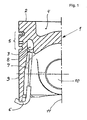
- Piston 1 depicted in half-section comprises a circumferential cooling channel 3 integrated in a piston head 2, which is positioned at a distance from a combustion chamber trough 4 centrally placed in the piston head 2 and a ring field 5.
- the cooling channel 3 is a coolant, especially the lubricant of the internal combustion engine acted upon.
- a position-fixed injection nozzle 6 is provided, starting from which, via a free jet 7, the coolant is injected into an inlet opening 8 communicating with the cooling channel 3. From there, the coolant flows through the cooling channel 3 and enters via a in the FIG. 3 shown outlet opening 22 from.
- the inflow opening 8 and the associated injector 6 are associated with a piston skirt 9 of the piston 1, and thereby offset or outside a pivot plane of a in the FIG. 1 not shown, connected to a pin bore 10 connecting rod.
- the outgoing from the injection nozzle 6, directed to the inflow opening 8 free jet 7 is inclined to a piston longitudinal axis eleventh
- FIG. 2 is shown as an individual part of a closed designed, soluble core 12, which is provided for the production of the cooling channel 3.
- the core 12, which is designed in particular as a salt core, is fixed in connection with a holding means on a casting mold, in particular on a casting core. After casting and cooling of the piston 1, the holding means and the core are rinsed out so that a cavity forming the cooling channel 3 in the piston 1 is established.
- the core 12 has geometrically changing structures, such as a corrugated or curved crest line 13, as well as on the upper side 14 and on the underside 15 circumferentially staggered arranged and / or differently formed stages 16a, 16b. As a result of this configuration of the core 12, flow cross sections of the cooling channel 3 which vary on the circumference vary.
- FIG. 3 schematically shows in a development a section of the cooling channel 3 and illustrates the geometric shape and design of the inner step-like or sawtooth-like structure of the cooling channel 3.
- a double inlet is provided, which is formed as an extended flow divider 19 and the two adjacent and corresponding arranged, designed as holes openings 18a, 18b includes.
- a local constriction 20 of the cooling channel 3 in the region of the flow divider 19 causes a deflection of the respective fluid streams after entry into the cooling channel 3, illustrated by the oppositely directed arrows.
- the expanded flow divider 19 includes rising and falling lower and upper segments, whereby a temporarily located in the double inlet coolant volume at a change of piston movement of the separate inflow openings in Direction of the discharge opening 9 is accelerated.
- the openings are 18a, 18b provided with a swirl structure 23a, 23b on the inner wall.
- a swirling motion is forced on the coolant flowing through, as a result of which an extended path is established.
Applications Claiming Priority (1)
| Application Number | Priority Date | Filing Date | Title |
|---|---|---|---|
| DE200610056012 DE102006056012A1 (de) | 2006-11-28 | 2006-11-28 | Variabel gestalteter Kühlkanal für einen Kolben |
Publications (1)
| Publication Number | Publication Date |
|---|---|
| EP1925805A1 true EP1925805A1 (fr) | 2008-05-28 |
Family
ID=39197156
Family Applications (1)
| Application Number | Title | Priority Date | Filing Date |
|---|---|---|---|
| EP07021851A Withdrawn EP1925805A1 (fr) | 2006-11-28 | 2007-11-10 | Canal de refroidissement variable pour un piston |
Country Status (2)
| Country | Link |
|---|---|
| EP (1) | EP1925805A1 (fr) |
| DE (1) | DE102006056012A1 (fr) |
Cited By (4)
| Publication number | Priority date | Publication date | Assignee | Title |
|---|---|---|---|---|
| DE102008028197A1 (de) * | 2008-06-12 | 2009-12-17 | Mahle International Gmbh | Kolben für einen Verbrennungsmotor und Verfahren zu seiner Herstellung |
| DE102008038324A1 (de) * | 2008-08-19 | 2010-02-25 | Mahle International Gmbh | Kühlkanal eines Kolbens für einen Verbrennungsmotor |
| CN104595052A (zh) * | 2014-10-30 | 2015-05-06 | 济南轻骑摩托车有限公司 | 一种摩托车发动机用活塞冷却机构 |
| EP3508714A1 (fr) * | 2018-01-09 | 2019-07-10 | MAN Truck & Bus AG | Piston pour un moteur à combustion interne |
Families Citing this family (2)
| Publication number | Priority date | Publication date | Assignee | Title |
|---|---|---|---|---|
| DE102009013201A1 (de) * | 2009-03-17 | 2010-09-23 | Ks Kolbenschmidt Gmbh | Kolben einer Brennkraftmaschine mit einem Kühlkanal mit einer Förderwirkung |
| DE102009001888C5 (de) * | 2009-03-26 | 2019-12-24 | Federal-Mogul Nürnberg GmbH | Kolben für einen Verbrennungsmotor |
Citations (13)
| Publication number | Priority date | Publication date | Assignee | Title |
|---|---|---|---|---|
| DE1751342B1 (de) * | 1968-05-14 | 1970-06-18 | Alcan Aluminiumwerke | Kolben mit im Kolbenkopf angeordnetem,ringfoermigem Kuehlkanal |
| JPH0561423U (ja) * | 1992-01-29 | 1993-08-13 | 株式会社豊田自動織機製作所 | ピストンの冷却装置 |
| US5595145A (en) * | 1995-05-31 | 1997-01-21 | Kabushiki Kaisha Komatsu Seisakusho | Cooling structure of diesel engine piston |
| DE19618625C1 (de) | 1996-05-09 | 1997-10-23 | Daimler Benz Ag | Flüssigkeitsgekühlter Kolben für Verbrennungsmotoren |
| DE19810937C1 (de) * | 1998-03-13 | 1999-11-25 | Daimler Chrysler Ag | Kolben für eine Brennkraftmaschine |
| DE19930630C1 (de) | 1999-07-02 | 2000-10-26 | Federal Mogul Nuernberg Gmbh | Flüssigkeitsgekühlter Kolben |
| EP1077322A1 (fr) * | 1999-08-16 | 2001-02-21 | Caterpillar Inc. | Lubrification d'axe de piston pour moteur à combustion |
| DE10126359A1 (de) | 2001-05-30 | 2003-01-02 | Federal Mogul Nuernberg Gmbh | Kolben für einen Verbrennungsmotor |
| DE10218999A1 (de) * | 2002-04-27 | 2003-11-13 | Ks Kolbenschmidt Gmbh | Kolben mit Ringträger und Formkühlkanal |
| DE10319230A1 (de) | 2003-04-28 | 2004-11-18 | Ks Kolbenschmidt Gmbh | Kolben mit Kühlkanal mit verbesserter Durchsatzleistung |
| WO2006027157A1 (fr) * | 2004-09-09 | 2006-03-16 | Federal-Mogul Nürnberg GmbH | Piston pour moteur a combustion interne, et moteur a combustion interne |
| DE102004056870A1 (de) * | 2004-11-25 | 2006-06-01 | Mahle International Gmbh | Kolben mit einem Kühlkanal für einen Verbrennungsmotor und Verfahren zur Herstellung des Kolbens |
| DE102004056769A1 (de) * | 2004-11-24 | 2006-06-01 | Federal-Mogul Nürnberg GmbH | Kolben für einen Verbrennungsmotor und Kombination eines Kolbens mit einer Öleinspritzanordnung |
Family Cites Families (1)
| Publication number | Priority date | Publication date | Assignee | Title |
|---|---|---|---|---|
| FR2844003B1 (fr) * | 2002-09-02 | 2006-06-16 | Bontaz Centre Sa | Gicleur a projections multiples pour refroidissement de moteur, et moteurs equipes de tels gicleurs |
-
2006
- 2006-11-28 DE DE200610056012 patent/DE102006056012A1/de not_active Ceased
-
2007
- 2007-11-10 EP EP07021851A patent/EP1925805A1/fr not_active Withdrawn
Patent Citations (13)
| Publication number | Priority date | Publication date | Assignee | Title |
|---|---|---|---|---|
| DE1751342B1 (de) * | 1968-05-14 | 1970-06-18 | Alcan Aluminiumwerke | Kolben mit im Kolbenkopf angeordnetem,ringfoermigem Kuehlkanal |
| JPH0561423U (ja) * | 1992-01-29 | 1993-08-13 | 株式会社豊田自動織機製作所 | ピストンの冷却装置 |
| US5595145A (en) * | 1995-05-31 | 1997-01-21 | Kabushiki Kaisha Komatsu Seisakusho | Cooling structure of diesel engine piston |
| DE19618625C1 (de) | 1996-05-09 | 1997-10-23 | Daimler Benz Ag | Flüssigkeitsgekühlter Kolben für Verbrennungsmotoren |
| DE19810937C1 (de) * | 1998-03-13 | 1999-11-25 | Daimler Chrysler Ag | Kolben für eine Brennkraftmaschine |
| DE19930630C1 (de) | 1999-07-02 | 2000-10-26 | Federal Mogul Nuernberg Gmbh | Flüssigkeitsgekühlter Kolben |
| EP1077322A1 (fr) * | 1999-08-16 | 2001-02-21 | Caterpillar Inc. | Lubrification d'axe de piston pour moteur à combustion |
| DE10126359A1 (de) | 2001-05-30 | 2003-01-02 | Federal Mogul Nuernberg Gmbh | Kolben für einen Verbrennungsmotor |
| DE10218999A1 (de) * | 2002-04-27 | 2003-11-13 | Ks Kolbenschmidt Gmbh | Kolben mit Ringträger und Formkühlkanal |
| DE10319230A1 (de) | 2003-04-28 | 2004-11-18 | Ks Kolbenschmidt Gmbh | Kolben mit Kühlkanal mit verbesserter Durchsatzleistung |
| WO2006027157A1 (fr) * | 2004-09-09 | 2006-03-16 | Federal-Mogul Nürnberg GmbH | Piston pour moteur a combustion interne, et moteur a combustion interne |
| DE102004056769A1 (de) * | 2004-11-24 | 2006-06-01 | Federal-Mogul Nürnberg GmbH | Kolben für einen Verbrennungsmotor und Kombination eines Kolbens mit einer Öleinspritzanordnung |
| DE102004056870A1 (de) * | 2004-11-25 | 2006-06-01 | Mahle International Gmbh | Kolben mit einem Kühlkanal für einen Verbrennungsmotor und Verfahren zur Herstellung des Kolbens |
Cited By (4)
| Publication number | Priority date | Publication date | Assignee | Title |
|---|---|---|---|---|
| DE102008028197A1 (de) * | 2008-06-12 | 2009-12-17 | Mahle International Gmbh | Kolben für einen Verbrennungsmotor und Verfahren zu seiner Herstellung |
| DE102008038324A1 (de) * | 2008-08-19 | 2010-02-25 | Mahle International Gmbh | Kühlkanal eines Kolbens für einen Verbrennungsmotor |
| CN104595052A (zh) * | 2014-10-30 | 2015-05-06 | 济南轻骑摩托车有限公司 | 一种摩托车发动机用活塞冷却机构 |
| EP3508714A1 (fr) * | 2018-01-09 | 2019-07-10 | MAN Truck & Bus AG | Piston pour un moteur à combustion interne |
Also Published As
| Publication number | Publication date |
|---|---|
| DE102006056012A1 (de) | 2008-05-29 |
Similar Documents
| Publication | Publication Date | Title |
|---|---|---|
| DE3032253C2 (de) | Verbrennungsmotor, insbesondere Dieselmotor | |
| EP1925805A1 (fr) | Canal de refroidissement variable pour un piston | |
| DE102006056013A1 (de) | Kühlkanalkolben | |
| EP1930578B1 (fr) | Variantes de canal de ventilation pour piston | |
| EP3339617B1 (fr) | Boîtier de cylindre, procédé de fabrication d'un boîtier de cylindre et noyau de coulée | |
| DE19618625C1 (de) | Flüssigkeitsgekühlter Kolben für Verbrennungsmotoren | |
| EP1778953B1 (fr) | Dispositif de nettoyage de turbine | |
| DE102014119701A1 (de) | Strukturelle Ausbildung (einer Turbinenschaufel) und Kühlung (derselben) | |
| DE3403624A1 (de) | Gebauter, fluessigkeitsgekuehlter kolben fuer brennkraftmaschinen | |
| EP0964981B1 (fr) | Aube de turbine et son utilisation dans un systeme de turbine a gaz | |
| DE4305407A1 (fr) | ||
| DE102010038055A1 (de) | Brennkraftmaschine mit Flüssigkeitskühlung | |
| AT505592A1 (de) | Kolben | |
| DE19859787A1 (de) | Gekühlte Turbinenschaufel | |
| EP3333398B1 (fr) | Culasse de cylindre | |
| DE1601563B2 (de) | Luftgekühlte Laufschaufel | |
| DE102019104814B4 (de) | Mit einem Einsatzträger ausgestattete Turbinenschaufel | |
| DE2530736C3 (de) | Thermisch belastetes Bauteil einer Brennkraftmaschine mit einer heißen Wand | |
| EP2440760A1 (fr) | Piston en métal léger à bol de combustion multi-cavité | |
| EP1231374B1 (fr) | Piston pour un moteur à combustion interne | |
| EP1207269B1 (fr) | Aube de turbine à gaz | |
| EP3208453B1 (fr) | Piston pour un moteur à combustion interne alternatif | |
| EP0154144B1 (fr) | Moteur à combustion interne refroidi par air | |
| DE19651175C2 (de) | Gegenkolben-Zweitakt-Verbrennungsmotor mit Direkteinspritzung des Kraftstoffes in den Zylinder und regelbarer Rotation und Turbulenz der Ladeluft | |
| DE19736135C1 (de) | Flüssigkeitsgekühlter Kolben für Verbrennungsmotoren |
Legal Events
| Date | Code | Title | Description |
|---|---|---|---|
| PUAI | Public reference made under article 153(3) epc to a published international application that has entered the european phase |
Free format text: ORIGINAL CODE: 0009012 |
|
| AK | Designated contracting states |
Kind code of ref document: A1 Designated state(s): AT BE BG CH CY CZ DE DK EE ES FI FR GB GR HU IE IS IT LI LT LU LV MC MT NL PL PT RO SE SI SK TR |
|
| AX | Request for extension of the european patent |
Extension state: AL BA HR MK RS |
|
| 17P | Request for examination filed |
Effective date: 20081113 |
|
| 17Q | First examination report despatched |
Effective date: 20090108 |
|
| AKX | Designation fees paid |
Designated state(s): AT BE BG CH CY CZ DE DK EE ES FI FR GB GR HU IE IS IT LI LT LU LV MC MT NL PL PT RO SE SI SK TR |
|
| RIN1 | Information on inventor provided before grant (corrected) |
Inventor name: OTTLICZKY, EMMERICH Inventor name: THIEL, NORMAN Inventor name: GRUBER, STEFAN Inventor name: RIES, NORBERT |
|
| RIN1 | Information on inventor provided before grant (corrected) |
Inventor name: OTTLICZKY, EMMERICH Inventor name: RIES, NORBERT Inventor name: THIEL, NORMAN Inventor name: GRUBER, STEFAN |
|
| STAA | Information on the status of an ep patent application or granted ep patent |
Free format text: STATUS: THE APPLICATION IS DEEMED TO BE WITHDRAWN |
|
| 18D | Application deemed to be withdrawn |
Effective date: 20160708 |