EP1925805A1 - Variably designed cooling duct for a piston - Google Patents
Variably designed cooling duct for a piston Download PDFInfo
- Publication number
- EP1925805A1 EP1925805A1 EP07021851A EP07021851A EP1925805A1 EP 1925805 A1 EP1925805 A1 EP 1925805A1 EP 07021851 A EP07021851 A EP 07021851A EP 07021851 A EP07021851 A EP 07021851A EP 1925805 A1 EP1925805 A1 EP 1925805A1
- Authority
- EP
- European Patent Office
- Prior art keywords
- cooling channel
- piston
- coolant
- flow
- piston according
- Prior art date
- Legal status (The legal status is an assumption and is not a legal conclusion. Google has not performed a legal analysis and makes no representation as to the accuracy of the status listed.)
- Withdrawn
Links
Images


Classifications
-
- F—MECHANICAL ENGINEERING; LIGHTING; HEATING; WEAPONS; BLASTING
- F02—COMBUSTION ENGINES; HOT-GAS OR COMBUSTION-PRODUCT ENGINE PLANTS
- F02F—CYLINDERS, PISTONS OR CASINGS, FOR COMBUSTION ENGINES; ARRANGEMENTS OF SEALINGS IN COMBUSTION ENGINES
- F02F3/00—Pistons
- F02F3/16—Pistons having cooling means
- F02F3/20—Pistons having cooling means the means being a fluid flowing through or along piston
- F02F3/22—Pistons having cooling means the means being a fluid flowing through or along piston the fluid being liquid
-
- B—PERFORMING OPERATIONS; TRANSPORTING
- B22—CASTING; POWDER METALLURGY
- B22C—FOUNDRY MOULDING
- B22C9/00—Moulds or cores; Moulding processes
- B22C9/10—Cores; Manufacture or installation of cores
- B22C9/105—Salt cores
-
- F—MECHANICAL ENGINEERING; LIGHTING; HEATING; WEAPONS; BLASTING
- F01—MACHINES OR ENGINES IN GENERAL; ENGINE PLANTS IN GENERAL; STEAM ENGINES
- F01P—COOLING OF MACHINES OR ENGINES IN GENERAL; COOLING OF INTERNAL-COMBUSTION ENGINES
- F01P3/00—Liquid cooling
- F01P3/06—Arrangements for cooling pistons
- F01P3/10—Cooling by flow of coolant through pistons
Definitions
- the invention relates to a liquid-cooled piston of an internal combustion engine, in which a radially encircling, a coolant leading cooling channel is integrated.
- the coolant circulating in the cooling channel enters via at least one inflow opening and via at least one outflow opening.
- the cooling channel includes measures for influencing a coolant flow.
- Pistons for internal combustion engines are exposed to high temperatures.
- an annular cooling channel is introduced, which is acted upon by the coolant, in particular the lubricating oil of the internal combustion engine.
- the circulating in the cooling channel coolant causes heat removal from the piston, which in particular the thermally highly stressed zones such as piston crown, combustion bowl, ring field and ring carrier are cooled specifically and effectively.
- a piston according to the preamble of claim 1 is known from DE 103 19 230 A1 known.
- the design of the cooling channel having an inflow opening and an outflow opening provides a constant inner and outer diameter, as well as a crest line extending in a plane.
- the inner wall includes circumferentially staggered structures.
- the cooling channel shows a over the entire length uniformly curved in the direction of the piston axis designed course, with always the same unchanged flow area.
- the invention has for its object to realize a cooling channel for a piston with improved heat dissipation, without adverse effect on the strength of the piston.
- the cooling channel has geometrically changing internal structures, including varying heights and widths, as well as a corrugated or curved top line. Associated with this are variably designed flow cross sections of the cooling channel.
- the inner diameter and / or outer diameter of the cooling channel is designed to be constant or fluctuating.
- the cooling channel can advantageously be designed such that different residence times of the coolant, which are matched to the respective thermal or mechanical loads of individual zones of the piston, are set in individual sections.
- the circumferentially changing, different cooling channel volumes containing flow cross sections of the cooling channel can be advantageously adapted to the critical areas of the piston depending on demand, whereby an increased thermal-mechanical load capacity of the piston can be achieved.
- a piston which includes a cooling channel with a changing flow cross-section.
- the cooling channel is formed diffuser-like, for which extends the flow cross-section of the cooling channel of the inflow opening continuously up to the discharge opening.
- the cooling channel comprises a double inlet, which comprises two adjacent, correspondingly arranged openings as the inflow opening.
- the coolant quantity entering the pump cooling channel and thus the throughput quantity are increased by the double inlet in conjunction with at least two injection nozzles, wherein advantageously each opening is assigned an injection nozzle.
- the cooling channel according to the invention which is also to be referred to as a double inlet pump channel, includes a flow divider which directly diverts the coolant jet outgoing from the injection nozzles into corresponding cooling channel sections downstream of the inflow opening, whereby two coolant streams flow countercurrently through the cooling channel up to the preferably common outflow opening.
- the cooling channel according to the invention in conjunction with the geometrically adapted double inlet and separately arranged injection nozzles, while maintaining the coolant flow, causes an increased coolant throughput and thus an increased efficiency.
- a one-piece, closed-shaped, soluble core is preferably used.
- This structure simplifies the manufacture and assembly of the core, which is designed in particular as a salt core, which can be fixed in connection with a holding means on the casting mold, in particular on a casting core. After casting the piston, the holding means and the core are flushed out, so that a cavity forming the cooling channel is established, and the openings for the inlet and outlet of the coolant.
- the one-piece core also improves the cooling.
- the one-piece core has improved stability, which has an advantageous effect on the manufacturing process and handling during assembly.
- All measures according to the invention result in ensuring advantageous for the cooling effect accelerated transport of the coolant within the cooling channel.
- the design of the cooling channel according to the invention simultaneously takes into account the different thermal and mechanical stresses of the piston, to achieve improved strength and reduced temperature, which advantageously adjusts an improved life of the piston.
- a preferred embodiment of the invention provides for the formation of the inner structure to provide the cooling channel circumferentially with staggered steps, which form coincidentally with a direction of a piston longitudinal axis on opposite inner sides of the cooling channel alternately inclined step surfaces.
- This approximately sawtooth-shaped, mutually offset cooling channel structure triggers a pumping action during the piston run.
- the structure which can also be referred to as a staircase-type topology, has the effect that the coolant entering the cooling channel continuously accelerates the transport under the influence of high acceleration forces, by the cooling of the coolant between the opposite inner sides or the floor surface and the ceiling surface Cooling channel leads.
- the invention also includes circumferentially mutually differently shaped step surfaces, for example, to locally influence the flow velocity of the coolant within the cooling channel.
- the inflow opening of the cooling channel, the two staggered openings includes is advantageously offset from a pivot axis of the connecting rod inserted within a piston skirt. This position of the openings allows an optimal arrangement of the injection nozzles, at the same time there is no adverse effect on the free jet, with which the coolant is injected.
- the inflow opening formed as a double inlet preferably further comprises an extended flow divider. This includes the closed between the double inlet, no interruption having cooling channel rising and falling lower and upper segments, which are designed so that a temporarily there befindliches coolant volume is accelerated in a change of piston movement of the separate openings, in the direction of the discharge opening ,
- the cooling channel is provided with swirl walls, for example in the area of the inflow opening or in any other alternative section of the cooling channel.
- a desired rapid exit of the heated coolant from the cooling channel causes a discharge opening formed as a flow collector.
- a flow collector according to the invention a locally flared portion of the cooling channel in the region of the discharge opening is provided, which reduces the flow velocity and ensures an unhindered discharge of the coolant, which improves the efficiency of the piston cooling.
- This structure improves the degree of filling the inflow opening and thus of the cooling channel with coolant, in comparison to an injection nozzle whose coolant jet is directed into a formed as a slot inflow opening.
- the two injection nozzles according to the invention are thus positioned less inclined, whereby the filling phases extend.
- the use of two similar injection nozzles with matching volumetric flows and coolant pressure, which in total have the same throughput as an equivalent individual nozzle, increases the coolant outlet velocity, which positively influences the filling and, associated therewith, the cooling effect.
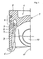
- Piston 1 depicted in half-section comprises a circumferential cooling channel 3 integrated in a piston head 2, which is positioned at a distance from a combustion chamber trough 4 centrally placed in the piston head 2 and a ring field 5.
- the cooling channel 3 is a coolant, especially the lubricant of the internal combustion engine acted upon.
- a position-fixed injection nozzle 6 is provided, starting from which, via a free jet 7, the coolant is injected into an inlet opening 8 communicating with the cooling channel 3. From there, the coolant flows through the cooling channel 3 and enters via a in the FIG. 3 shown outlet opening 22 from.
- the inflow opening 8 and the associated injector 6 are associated with a piston skirt 9 of the piston 1, and thereby offset or outside a pivot plane of a in the FIG. 1 not shown, connected to a pin bore 10 connecting rod.
- the outgoing from the injection nozzle 6, directed to the inflow opening 8 free jet 7 is inclined to a piston longitudinal axis eleventh
- FIG. 2 is shown as an individual part of a closed designed, soluble core 12, which is provided for the production of the cooling channel 3.
- the core 12, which is designed in particular as a salt core, is fixed in connection with a holding means on a casting mold, in particular on a casting core. After casting and cooling of the piston 1, the holding means and the core are rinsed out so that a cavity forming the cooling channel 3 in the piston 1 is established.
- the core 12 has geometrically changing structures, such as a corrugated or curved crest line 13, as well as on the upper side 14 and on the underside 15 circumferentially staggered arranged and / or differently formed stages 16a, 16b. As a result of this configuration of the core 12, flow cross sections of the cooling channel 3 which vary on the circumference vary.
- FIG. 3 schematically shows in a development a section of the cooling channel 3 and illustrates the geometric shape and design of the inner step-like or sawtooth-like structure of the cooling channel 3.
- a double inlet is provided, which is formed as an extended flow divider 19 and the two adjacent and corresponding arranged, designed as holes openings 18a, 18b includes.
- a local constriction 20 of the cooling channel 3 in the region of the flow divider 19 causes a deflection of the respective fluid streams after entry into the cooling channel 3, illustrated by the oppositely directed arrows.
- the expanded flow divider 19 includes rising and falling lower and upper segments, whereby a temporarily located in the double inlet coolant volume at a change of piston movement of the separate inflow openings in Direction of the discharge opening 9 is accelerated.
- the openings are 18a, 18b provided with a swirl structure 23a, 23b on the inner wall.
- a swirling motion is forced on the coolant flowing through, as a result of which an extended path is established.
Landscapes
- Engineering & Computer Science (AREA)
- Mechanical Engineering (AREA)
- Chemical & Material Sciences (AREA)
- Combustion & Propulsion (AREA)
- General Engineering & Computer Science (AREA)
- Physics & Mathematics (AREA)
- Fluid Mechanics (AREA)
- Pistons, Piston Rings, And Cylinders (AREA)
Abstract
Description
Die Erfindung betrifft einen flüssigkeitsgekühlten Kolben einer Brennkraftmaschine, in dem ein radial umlaufender, ein Kühlmittel führender Kühlkanal integriert ist. Das in dem Kühlkanal zirkulierende Kühlmittel tritt über zumindest eine Zuströmöffnung ein und über zumindest eine Abströmöffnung aus. Zur Erzielung einer Pumpwirkung schließt der Kühlkanal Maßnahmen zur Beeinflussung einer Kühlmittelströmung ein.The invention relates to a liquid-cooled piston of an internal combustion engine, in which a radially encircling, a coolant leading cooling channel is integrated. The coolant circulating in the cooling channel enters via at least one inflow opening and via at least one outflow opening. To achieve a pumping action, the cooling channel includes measures for influencing a coolant flow.
Kolben für Brennkraftmaschinen sind hohen Temperaturen ausgesetzt. Zur gezielten und wirksamen Kühlung, mit der die Lebensdauer verbessert werden kann, ist in dem Kolben ein ringförmiger Kühlkanal eingebracht, der von dem Kühlmittel, insbesondere dem Schmieröl der Brennkraftmaschine, beaufschlagt wird. Das in dem Kühlkanal zirkulierende Kühlmittel bewirkt eine Wärmeabfuhr aus dem Kolben, wodurch insbesondere die thermisch hoch beanspruchten Zonen wie Kolbenboden, Brennraummulde, Ringfeld und Ringträger gezielt und wirksam gekühlt werden.Pistons for internal combustion engines are exposed to high temperatures. For targeted and effective cooling, with which the service life can be improved, in the piston, an annular cooling channel is introduced, which is acted upon by the coolant, in particular the lubricating oil of the internal combustion engine. The circulating in the cooling channel coolant causes heat removal from the piston, which in particular the thermally highly stressed zones such as piston crown, combustion bowl, ring field and ring carrier are cooled specifically and effectively.
Ein Kolben gemäß dem Oberbegriff des Anspruchs 1 ist aus der
Als Maßnahme, um die abgeführte Wärmemenge aus dem Kolben zu erhöhen, ist gemäß der
Diese Maßnahme vergrößert die Oberfläche des Kühlkanals, führt aber anderseits zu einer nachteiligen Beeinflussung der Zirkulation des Kühlmittels. Der wellenförmige Verlauf des Kühlkanals in Verbindung mit der oszillierenden Kolbenbewegung verhindert eine kontinuierliche Strömung, da sich das Kühlmittel stets an den Vertiefungen des Kühlkanals sammelt und eine Weiterleitung zu der Abströmöffnung behindert.This measure increases the surface of the cooling channel, but on the other hand leads to an adverse effect on the circulation of the coolant. The wave-shaped course of the cooling channel in conjunction with the oscillating piston movement prevents continuous flow, since the coolant always collects at the recesses of the cooling channel and obstructs a forwarding to the outflow opening.
Der Erfindung liegt die Aufgabe zugrunde, einen Kühlkanal für einen Kolben mit einer verbesserten Wärmeabführung zu realisieren, ohne nachteiligen Einfluss auf die Festigkeit des Kolbens.The invention has for its object to realize a cooling channel for a piston with improved heat dissipation, without adverse effect on the strength of the piston.
Diese Aufgabe wird erfindungsgemäß durch die Merkmale des Patentanspruchs 1 gelöst.This object is achieved by the features of
Zur Darstellung eines Pump-Kühlkanals ist erfindungsgemäß vorgesehen, dass der Kühlkanal geometrisch wechselnde Innenstrukturen aufweist, variierende Höhen und Breiten, sowie eine wellenförmig bzw. gekrümmt verlaufende Scheitellinie einschließt. Damit verbunden stellen sich variabel ausgelegte Durchströmquerschnitte des Kühlkanals ein. Der Innendurchmesser und/oder Außendurchmesser des Kühlkanals ist dazu konstant oder schwankend ausgelegt. Gemäß der Erfindung kann der Kühlkanal vorteilhaft so gestaltet werden, dass sich unterschiedliche, auf die jeweiligen thermischen oder mechanischen Belastungen einzelner Zonen des Kolbens abgestimmte Verweilzeiten des Kühlmittels in einzelnen Abschnitten einstellen. Die sich umfangsseitig ändernden, unterschiedliche Kühlkanalvolumina beinhaltenden Durchströmquerschnitte des Kühlkanals können vorteilhaft bedarfsabhängig den kritischen Bereichen des Kolbens anpasst werden, wodurch eine gesteigerte thermisch-mechanische Belastbarkeit des Kolbens erzielbar ist.In order to present a pump cooling channel, it is provided according to the invention that the cooling channel has geometrically changing internal structures, including varying heights and widths, as well as a corrugated or curved top line. Associated with this are variably designed flow cross sections of the cooling channel. The inner diameter and / or outer diameter of the cooling channel is designed to be constant or fluctuating. According to the invention, the cooling channel can advantageously be designed such that different residence times of the coolant, which are matched to the respective thermal or mechanical loads of individual zones of the piston, are set in individual sections. The circumferentially changing, different cooling channel volumes containing flow cross sections of the cooling channel can be advantageously adapted to the critical areas of the piston depending on demand, whereby an increased thermal-mechanical load capacity of the piston can be achieved.
Aus der
Ein weiteres Gestaltungsmerkmal der Erfindung bezieht sich auf die Kühlmittelbeaufschlagung des Kühlkanals. Zur verbesserten, maximalen Befüllung umfasst der Kühlkanal einen Doppeleinlass, der als Zuströmöffnung zwei benachbarte, korrespondierend angeordnete Öffnungen umfasst. Die in den Pump-Kühlkanal eintretende Kühlmittelmenge und damit die Durchsatzmenge wird durch den Doppeleinlass in Verbindung mit mindestens zwei Einspritzdüsen gesteigert, wobei vorteilhaft jeder Öffnung eine Einspritzdüse zugeordnet ist. Zudem schließt der auch als Doppeleinlass-Pumpkanal zu bezeichnende erfindungsgemäße Kühlkanal einen Strömungsteiler ein, der den von den Einspritzdüsen jeweils ausgehenden Kühlmittelstrahl nach der Zuströmöffnung unmittelbar in zugehörige Kühlkanalabschnitte umlenkt, wodurch zwei Kühlmittelströme im Gegenstrom den Kühlkanal bis zu der vorzugsweise gemeinsamen Abströmöffnung durchströmen. Der erfindungsgemäße Kühlkanal in Verbindung mit dem geometrisch angepassten Doppeleinlass und getrennt angeordneten Einspritzdüsen bewirkt bei einer Beibehaltung des Kühlmittelstroms einen vergrößerten Kühlmitteldurchsatz und damit einen gesteigerten Wirkungsgrad.Another design feature of the invention relates to the coolant loading of the cooling channel. For improved, maximum filling, the cooling channel comprises a double inlet, which comprises two adjacent, correspondingly arranged openings as the inflow opening. The coolant quantity entering the pump cooling channel and thus the throughput quantity are increased by the double inlet in conjunction with at least two injection nozzles, wherein advantageously each opening is assigned an injection nozzle. In addition, the cooling channel according to the invention, which is also to be referred to as a double inlet pump channel, includes a flow divider which directly diverts the coolant jet outgoing from the injection nozzles into corresponding cooling channel sections downstream of the inflow opening, whereby two coolant streams flow countercurrently through the cooling channel up to the preferably common outflow opening. The cooling channel according to the invention, in conjunction with the geometrically adapted double inlet and separately arranged injection nozzles, while maintaining the coolant flow, causes an increased coolant throughput and thus an increased efficiency.
Zur Herstellung des erfindungsgemäßen Kühlkanals wird bevorzugt ein einteiliger, geschlossen gestalteter, löslicher Kern eingesetzt. Dieser Aufbau vereinfacht die Herstellung und die Montage des insbesondere als Salzkern ausgebildeten Kerns, der in Verbindung mit einem Haltemittel an der Gießform, insbesondere an einem Gießkern fixiert werden kann. Nach dem Gießen des Kolbens werden die Haltemittel und der Kern ausgespült, so dass sich ein den Kühlkanal bildender Hohlraum einstellt, sowie die Öffnungen zum Eintritt und Austritt des Kühlmittels. Im Vergleich zu einem zwischen den Zuströmöffnungen unterbrochen Kern verbessert der einteilige Kern außerdem die Kühlung. Außerdem besitzt der einteilige Kern eine verbesserte Stabilität, was sich vorteilhaft auf den Herstellprozess und das Handling bei der Montage auswirkt.To produce the cooling channel according to the invention, a one-piece, closed-shaped, soluble core is preferably used. This structure simplifies the manufacture and assembly of the core, which is designed in particular as a salt core, which can be fixed in connection with a holding means on the casting mold, in particular on a casting core. After casting the piston, the holding means and the core are flushed out, so that a cavity forming the cooling channel is established, and the openings for the inlet and outlet of the coolant. Compared in addition to a core interrupted between the inflow openings, the one-piece core also improves the cooling. In addition, the one-piece core has improved stability, which has an advantageous effect on the manufacturing process and handling during assembly.
Alle erfindungsgemäßen Maßnahmen führen dazu, einen für die Kühlwirkung vorteilhaften beschleunigten Transport des Kühlmittels innerhalb des Kühlkanals zu gewährleisten. Die Auslegung des erfindungsgemäßen Kühlkanals berücksichtigt gleichzeitig die unterschiedlichen thermischen und mechanischen Beanspruchungen des Kolbens, zur Erzielung einer verbesserten Festigkeit und reduzierter Temperatur, wodurch sich vorteilhaft eine verbesserte Lebensdauer des Kolbens einstellt.All measures according to the invention result in ensuring advantageous for the cooling effect accelerated transport of the coolant within the cooling channel. The design of the cooling channel according to the invention simultaneously takes into account the different thermal and mechanical stresses of the piston, to achieve improved strength and reduced temperature, which advantageously adjusts an improved life of the piston.
Weitere vorteilhafte Ausgestaltungen der Erfindung sind Gegenstand der abhängigen . Ansprüche 2 bis 9.Further advantageous embodiments of the invention are the subject of the dependent.
Eine bevorzugte Weiterbildung der Erfindung sieht zur Ausbildung der Innenstruktur vor, den Kühlkanal umfangsseitig mit gegeneinander versetzten Stufen zu versehen, die übereinstimmend mit einer Richtung einer Kolbenlängsachse an gegenüberliegenden Innenseiten des Kühlkanals wechselweise schräg verlaufende Stufenflächen bilden. Diese angenähert sägezahnartig ausgebildete, zueinander versetzte Kühlkanalstruktur löst bei dem Kolbenlauf eine Pumpwirkung aus. Die auch als treppenartige Topologie zu bezeichnende Struktur hat die Wirkung, dass das in den Kühlkanal eintretende Kühlmittel unter dem Einfluss hoher Beschleunigungskräfte, durch das Hin- und Herschleudern des Kühlmittels zwischen den gegenüberliegenden Innenseiten bzw. der Bodenfläche und der Deckenfläche kontinuierlich zu einem beschleunigten Transport des Kühlkanals führt. Die Erfindung schließt dabei auch umfangsseitig zueinander unterschiedlich geformte Stufenflächen ein, um beispielsweise die Strömungsgeschwindigkeit des Kühlmittels innerhalb des Kühlkanals lokal zu beeinflussen.A preferred embodiment of the invention provides for the formation of the inner structure to provide the cooling channel circumferentially with staggered steps, which form coincidentally with a direction of a piston longitudinal axis on opposite inner sides of the cooling channel alternately inclined step surfaces. This approximately sawtooth-shaped, mutually offset cooling channel structure triggers a pumping action during the piston run. The structure, which can also be referred to as a staircase-type topology, has the effect that the coolant entering the cooling channel continuously accelerates the transport under the influence of high acceleration forces, by the cooling of the coolant between the opposite inner sides or the floor surface and the ceiling surface Cooling channel leads. The invention also includes circumferentially mutually differently shaped step surfaces, for example, to locally influence the flow velocity of the coolant within the cooling channel.
Die Zuströmöffnung des Kühlkanals, die zwei versetzt angeordnete Öffnungen einschließt, ist vorteilhaft versetzt zu einer Schwenkachse des Pleuels innerhalb eines Kolbenschaftes eingebracht. Diese Lage der Öffnungen ermöglicht eine optimale Anordnung der Einspritzdüsen, wobei gleichzeitig keine nachteilige Beeinflussung des Freistrahls erfolgt, mit dem das Kühlmittel eingespritzt wird.The inflow opening of the cooling channel, the two staggered openings includes is advantageously offset from a pivot axis of the connecting rod inserted within a piston skirt. This position of the openings allows an optimal arrangement of the injection nozzles, at the same time there is no adverse effect on the free jet, with which the coolant is injected.
Die als ein Doppeleinlass ausgebildete Zuströmöffnung umfasst bevorzugt weiterhin einen erweiterten Strömungsteiler. Dazu schließt der zwischen dem Doppeleinlass geschlossene, keine Unterbrechung aufweisende Kühlkanal ansteigende und abfallende untere und obere Segmente ein, die so gestaltet sind, dass ein sich dort temporär befindliches Kühlmittelvolumen bei einem Wechsel der Kolbenbewegung von den getrennten Öffnungen ausgehend, in Richtung der Abströmöffnung beschleunigt wird.The inflow opening formed as a double inlet preferably further comprises an extended flow divider. This includes the closed between the double inlet, no interruption having cooling channel rising and falling lower and upper segments, which are designed so that a temporarily there befindliches coolant volume is accelerated in a change of piston movement of the separate openings, in the direction of the discharge opening ,
Um die Wärmeaufnahme in thermisch hochbeanspruchten Zonen des Kolbens zu verbessern, ist der Kühlkanal beispielsweise im Bereich der Zuströmöffnung oder in einem beliebigen weiteren alternativen Abschnitt des Kühlkanals mit Drallwandungen versehen. Durch diese Maßnahme wird dem durchströmenden Kühlmittel eine Drallbewegung aufgezwungen, wodurch sich eine vergrößerte, die Wärmeaufnahmezeit verlängernde Wegstrecke des Kühlmittels einstellt, ohne dabei die Strömungsgeschwindigkeit nachteilig zu beeinflussen.In order to improve the heat absorption in thermally highly stressed zones of the piston, the cooling channel is provided with swirl walls, for example in the area of the inflow opening or in any other alternative section of the cooling channel. As a result of this measure, a swirling motion is imposed on the coolant flowing through, as a result of which an enlarged path length of the coolant which extends the heat absorption time is established, without detrimentally influencing the flow velocity.
Ein gewünschter schneller Austritt des erwärmten Kühlmittels aus dem Kühlkanal bewirkt eine als Strömungssammler ausgebildete Abströmöffnung. Als Strömungssammler ist erfindungsgemäß ein lokal aufgeweiteter Abschnitt des Kühlkanals im Bereich der Abströmöffnung vorgesehen, der die Strömungsgeschwindigkeit reduziert und einen ungehinderten Austritt des Kühlmittels sicherstellt, was die Wirksamkeit der Kolbenkühlung verbessert.A desired rapid exit of the heated coolant from the cooling channel causes a discharge opening formed as a flow collector. As a flow collector according to the invention a locally flared portion of the cooling channel in the region of the discharge opening is provided, which reduces the flow velocity and ensures an unhindered discharge of the coolant, which improves the efficiency of the piston cooling.
Eine optimierte Beaufschlagung der als Doppeleinlass ausgebildeten, zwei getrennte Öffnungen einschließenden Zuströmöffnung, erfolgt gemäß der Erfindung über zwei getrennt positionierte Einspritzdüsen. Dieser Aufbau verbessert den Befüllungsgrad der Zuströmöffnung und damit des Kühlkanals mit Kühlmittel, im Vergleich zu einer Einspritzdüse deren Kühlmittelstrahl in eine als Langloch ausgebildete Zuströmöffnung gerichtet ist. Die zwei Einspritzdüsen gemäß der Erfindung sind folglich weniger stark geneigt positioniert, wodurch sich die Befüllungsphasen verlängern. Die Anwendung von zwei gleichartigen Einspritzdüsen mit übereinstimmendem Volumenströmen und Kühlmitteldruck, die in Summe den gleichen Durchsatz wie eine äquivalente Einzeldüse haben, erhöht die Kühlmittel-Austrittsgeschwindigkeit, was die Füllung und damit verbunden die Kühlwirkung positiv beeinflusst. Gemäß einer vorteilhaften Ausgestaltung bietet sich an, die Einspritzdüsen ortsfest so zu fixierten, damit das Kühlmittel in einem weitestgehend parallel zu der Kolbenlängsachse ausgerichteten Freistrahl senkrecht in die Zuströmöffnungen eingespritzt wird.An optimized admission of the double inlet formed, two separate openings enclosing inflow, takes place according to the invention via two separately positioned injection nozzles. This structure improves the degree of filling the inflow opening and thus of the cooling channel with coolant, in comparison to an injection nozzle whose coolant jet is directed into a formed as a slot inflow opening. The two injection nozzles according to the invention are thus positioned less inclined, whereby the filling phases extend. The use of two similar injection nozzles with matching volumetric flows and coolant pressure, which in total have the same throughput as an equivalent individual nozzle, increases the coolant outlet velocity, which positively influences the filling and, associated therewith, the cooling effect. According to an advantageous embodiment, it is advisable to fix the injection nozzles in a stationary manner so that the coolant is injected perpendicularly into the inflow openings in a free jet directed as far as possible parallel to the piston longitudinal axis.
Ausführungsbeispiele der Erfindung, auf die diese jedoch nicht beschränkt ist, werden nachfolgend beschrieben und anhand der Figuren erläutert.Embodiments of the invention, to which this is not limited, are described below and explained with reference to the figures.
Es zeigen:
- Fig.1:
- in einem Halbschnitt einen flüssigkeitsgekühlten Kolben bekannter Bauform,
- Fig.2:
- in einer Perspektive einen einteilig geschlossen gestalteten, löslichen Kern, der zur Herstellung eines Kühlkanals bestimmt ist,
- Fig.3:
- schematisch einen Abwicklungsausschnitt des Kühlkanals, der die als Doppelleinlass ausgebildete Zuströmöffnung verdeutlicht.
- Fig.1:
- in a half section a liquid-cooled piston of known design,
- Figure 2:
- in a perspective, a one-piece closed designed, soluble core, which is intended for the production of a cooling channel,
- Figure 3:
- schematically a development cutout of the cooling channel, which illustrates the inlet opening formed as a double inlet.
Der in
In der
Die
- 11
- Kolbenpiston
- 22
- Kolbenbodenpiston crown
- 33
- Kühlkanalcooling channel
- 44
- BrennraummuldeCombustion bowl
- 55
- Ringfeldring box
- 66
- Einspritzdüseinjection
- 77
- Freistrahlfree jet
- 88th
- Zuströmöffnunginflow
- 99
- Kolbenschaftpiston shaft
- 1010
- Bolzenbohrungpin bore
- 1111
- Kolbenlängsachsepiston longitudinal axis
- 1212
- Kerncore
- 1313
- Scheitelliniecrest line
- 1414
- Oberseitetop
- 1515
- Unterseitebottom
- 16a16a
- Stufestep
- 16b16b
- Stufestep
- 17a17a
- Stufenflächestep surface
- 17b17b
- Stufenflächestep surface
- 18a18a
- Öffnungopening
- 18b18b
- Öffnungopening
- 1919
- Strömungsteilerflow divider
- 2020
- Verengungnarrowing
- 2121
- Strömungssammlerflow collector
- 2222
- Abströmöffnungoutflow
- 23a23a
- Drallstrukturswirl structure
- 23b23b
- Drallstrukturswirl structure
Claims (9)
Applications Claiming Priority (1)
| Application Number | Priority Date | Filing Date | Title |
|---|---|---|---|
| DE200610056012 DE102006056012A1 (en) | 2006-11-28 | 2006-11-28 | Variable design cooling channel for one piston |
Publications (1)
| Publication Number | Publication Date |
|---|---|
| EP1925805A1 true EP1925805A1 (en) | 2008-05-28 |
Family
ID=39197156
Family Applications (1)
| Application Number | Title | Priority Date | Filing Date |
|---|---|---|---|
| EP07021851A Withdrawn EP1925805A1 (en) | 2006-11-28 | 2007-11-10 | Variably designed cooling duct for a piston |
Country Status (2)
| Country | Link |
|---|---|
| EP (1) | EP1925805A1 (en) |
| DE (1) | DE102006056012A1 (en) |
Cited By (4)
| Publication number | Priority date | Publication date | Assignee | Title |
|---|---|---|---|---|
| DE102008028197A1 (en) * | 2008-06-12 | 2009-12-17 | Mahle International Gmbh | Piston e.g. single-part cast piston, for internal combustion engine, has cooling channel running around piston crown at height of ring part, where surface of cooling channel includes circulating grooves that run parallel to each other |
| DE102008038324A1 (en) * | 2008-08-19 | 2010-02-25 | Mahle International Gmbh | Cooling channel of a piston for an internal combustion engine |
| CN104595052A (en) * | 2014-10-30 | 2015-05-06 | 济南轻骑摩托车有限公司 | Motorcycle engine piston cooling mechanism |
| EP3508714A1 (en) * | 2018-01-09 | 2019-07-10 | MAN Truck & Bus AG | Piston for a combustion engine |
Families Citing this family (2)
| Publication number | Priority date | Publication date | Assignee | Title |
|---|---|---|---|---|
| DE102009013201A1 (en) * | 2009-03-17 | 2010-09-23 | Ks Kolbenschmidt Gmbh | Piston for internal-combustion engine, has cooling channel in piston head, where cooling channel includes upper partial segments and lower partial segments with transition flanks that rise or lower with reference to piston stroke axis |
| DE102009001888C5 (en) * | 2009-03-26 | 2019-12-24 | Federal-Mogul Nürnberg GmbH | Pistons for an internal combustion engine |
Citations (13)
| Publication number | Priority date | Publication date | Assignee | Title |
|---|---|---|---|---|
| DE1751342B1 (en) * | 1968-05-14 | 1970-06-18 | Alcan Aluminiumwerke | Piston with ring-shaped cooling channel arranged in the piston head |
| JPH0561423U (en) * | 1992-01-29 | 1993-08-13 | 株式会社豊田自動織機製作所 | Piston cooling system |
| US5595145A (en) * | 1995-05-31 | 1997-01-21 | Kabushiki Kaisha Komatsu Seisakusho | Cooling structure of diesel engine piston |
| DE19618625C1 (en) | 1996-05-09 | 1997-10-23 | Daimler Benz Ag | Liquid-cooled pistons for internal combustion engines |
| DE19810937C1 (en) * | 1998-03-13 | 1999-11-25 | Daimler Chrysler Ag | Pistons for an internal combustion engine |
| DE19930630C1 (en) | 1999-07-02 | 2000-10-26 | Federal Mogul Nuernberg Gmbh | Liquid-cooled piston for I.C. engines has an annular cooling channel that runs in an undulating fashion in the direction of the piston axis |
| EP1077322A1 (en) * | 1999-08-16 | 2001-02-21 | Caterpillar Inc. | Internal combustion engine piston pin lubrication |
| DE10126359A1 (en) | 2001-05-30 | 2003-01-02 | Federal Mogul Nuernberg Gmbh | Internal combustion engine piston with cooling channel slopes channel downward from inlet to outlet and has channel floor corrugated locally with offset crests and one crest at inlet floor. |
| DE10218999A1 (en) * | 2002-04-27 | 2003-11-13 | Ks Kolbenschmidt Gmbh | Ring holder and profiled cooling channel for piston incorporates groove formed by casting or turning and cooling channel with thickened portions on outside of otherwise circular channel |
| DE10319230A1 (en) | 2003-04-28 | 2004-11-18 | Ks Kolbenschmidt Gmbh | Piston for internal combustion engine has radially encompassing cooling passage formed in piston crown with rising and falling sections in such way that cooling medium is accelerated from inlet in direction of outlet of passage |
| WO2006027157A1 (en) * | 2004-09-09 | 2006-03-16 | Federal-Mogul Nürnberg GmbH | Piston for a combustion engine, and combustion engine |
| DE102004056769A1 (en) * | 2004-11-24 | 2006-06-01 | Federal-Mogul Nürnberg GmbH | Piston for an internal combustion engine and combination of a piston with an oil injection assembly |
| DE102004056870A1 (en) * | 2004-11-25 | 2006-06-01 | Mahle International Gmbh | Piston having a cooling passage for an internal combustion engine and method of manufacturing the piston |
Family Cites Families (1)
| Publication number | Priority date | Publication date | Assignee | Title |
|---|---|---|---|---|
| FR2844003B1 (en) * | 2002-09-02 | 2006-06-16 | Bontaz Centre Sa | MULTI-PROJECTION SPRINKLER FOR ENGINE COOLING, AND ENGINES EQUIPPED WITH SUCH SPRAYERS |
-
2006
- 2006-11-28 DE DE200610056012 patent/DE102006056012A1/en not_active Ceased
-
2007
- 2007-11-10 EP EP07021851A patent/EP1925805A1/en not_active Withdrawn
Patent Citations (13)
| Publication number | Priority date | Publication date | Assignee | Title |
|---|---|---|---|---|
| DE1751342B1 (en) * | 1968-05-14 | 1970-06-18 | Alcan Aluminiumwerke | Piston with ring-shaped cooling channel arranged in the piston head |
| JPH0561423U (en) * | 1992-01-29 | 1993-08-13 | 株式会社豊田自動織機製作所 | Piston cooling system |
| US5595145A (en) * | 1995-05-31 | 1997-01-21 | Kabushiki Kaisha Komatsu Seisakusho | Cooling structure of diesel engine piston |
| DE19618625C1 (en) | 1996-05-09 | 1997-10-23 | Daimler Benz Ag | Liquid-cooled pistons for internal combustion engines |
| DE19810937C1 (en) * | 1998-03-13 | 1999-11-25 | Daimler Chrysler Ag | Pistons for an internal combustion engine |
| DE19930630C1 (en) | 1999-07-02 | 2000-10-26 | Federal Mogul Nuernberg Gmbh | Liquid-cooled piston for I.C. engines has an annular cooling channel that runs in an undulating fashion in the direction of the piston axis |
| EP1077322A1 (en) * | 1999-08-16 | 2001-02-21 | Caterpillar Inc. | Internal combustion engine piston pin lubrication |
| DE10126359A1 (en) | 2001-05-30 | 2003-01-02 | Federal Mogul Nuernberg Gmbh | Internal combustion engine piston with cooling channel slopes channel downward from inlet to outlet and has channel floor corrugated locally with offset crests and one crest at inlet floor. |
| DE10218999A1 (en) * | 2002-04-27 | 2003-11-13 | Ks Kolbenschmidt Gmbh | Ring holder and profiled cooling channel for piston incorporates groove formed by casting or turning and cooling channel with thickened portions on outside of otherwise circular channel |
| DE10319230A1 (en) | 2003-04-28 | 2004-11-18 | Ks Kolbenschmidt Gmbh | Piston for internal combustion engine has radially encompassing cooling passage formed in piston crown with rising and falling sections in such way that cooling medium is accelerated from inlet in direction of outlet of passage |
| WO2006027157A1 (en) * | 2004-09-09 | 2006-03-16 | Federal-Mogul Nürnberg GmbH | Piston for a combustion engine, and combustion engine |
| DE102004056769A1 (en) * | 2004-11-24 | 2006-06-01 | Federal-Mogul Nürnberg GmbH | Piston for an internal combustion engine and combination of a piston with an oil injection assembly |
| DE102004056870A1 (en) * | 2004-11-25 | 2006-06-01 | Mahle International Gmbh | Piston having a cooling passage for an internal combustion engine and method of manufacturing the piston |
Cited By (4)
| Publication number | Priority date | Publication date | Assignee | Title |
|---|---|---|---|---|
| DE102008028197A1 (en) * | 2008-06-12 | 2009-12-17 | Mahle International Gmbh | Piston e.g. single-part cast piston, for internal combustion engine, has cooling channel running around piston crown at height of ring part, where surface of cooling channel includes circulating grooves that run parallel to each other |
| DE102008038324A1 (en) * | 2008-08-19 | 2010-02-25 | Mahle International Gmbh | Cooling channel of a piston for an internal combustion engine |
| CN104595052A (en) * | 2014-10-30 | 2015-05-06 | 济南轻骑摩托车有限公司 | Motorcycle engine piston cooling mechanism |
| EP3508714A1 (en) * | 2018-01-09 | 2019-07-10 | MAN Truck & Bus AG | Piston for a combustion engine |
Also Published As
| Publication number | Publication date |
|---|---|
| DE102006056012A1 (en) | 2008-05-29 |
Similar Documents
| Publication | Publication Date | Title |
|---|---|---|
| EP1925805A1 (en) | Variably designed cooling duct for a piston | |
| EP3339617B1 (en) | Cylinder housing, method for producing a cylinder housing and casting core | |
| DE102006056013A1 (en) | Piston for internal-combustion engine, has radially rotating cooling ducts spaced apart from each other and integrated to piston head and ring zone, and forming vertically aligned cross sectional profile | |
| EP1930578B1 (en) | Cooling duct variant for pistons | |
| DE19618625C1 (en) | Liquid-cooled pistons for internal combustion engines | |
| EP1778953B1 (en) | Exhaust turbine cleaning device | |
| CH709095A2 (en) | Turbine blade with a chamber for receiving the flow of a coolant. | |
| DE3403624A1 (en) | BUILT LIQUID-COOLED PISTON FOR INTERNAL COMBUSTION ENGINES | |
| EP0964981B1 (en) | Turbine blade and its use in a gas turbine system | |
| DE102010038055A1 (en) | Internal combustion engine with liquid cooling | |
| DE4305407A1 (en) | ||
| AT505592A1 (en) | Piston for cylinder for two stroke engine with piston ring, has two skirt walls, which are connected by self-supporting support wall, which is placed at distance from piston head | |
| EP3333398B1 (en) | Cylinder head | |
| EP2440760A1 (en) | Light-metal piston having a multiple omega-shaped combustion bowl | |
| DE1601563B2 (en) | Air-cooled blade | |
| DE102019104814B4 (en) | Turbine blade equipped with an insert carrier | |
| DE2530736C3 (en) | Thermally loaded component of an internal combustion engine with a hot wall | |
| EP1231374B1 (en) | Piston for an internal combustion engine | |
| EP1207269B1 (en) | Gas turbine vane | |
| EP3208453B1 (en) | Piston for a reciprocating piston combustion engine | |
| EP0154144B1 (en) | Air-cooled internal-combustion piston engine | |
| DE19651175C2 (en) | Counter-piston two-stroke internal combustion engine with direct fuel injection into the cylinder and adjustable rotation and turbulence of the charge air | |
| DE19736135C1 (en) | Liquid cooled piston for internal combustion engine | |
| DE69102656T2 (en) | CYLINDER RIFLE FOR A WATER-COOLED INTERNAL COMBUSTION ENGINE. | |
| EP1391583B1 (en) | Air cooled transition duct |
Legal Events
| Date | Code | Title | Description |
|---|---|---|---|
| PUAI | Public reference made under article 153(3) epc to a published international application that has entered the european phase |
Free format text: ORIGINAL CODE: 0009012 |
|
| AK | Designated contracting states |
Kind code of ref document: A1 Designated state(s): AT BE BG CH CY CZ DE DK EE ES FI FR GB GR HU IE IS IT LI LT LU LV MC MT NL PL PT RO SE SI SK TR |
|
| AX | Request for extension of the european patent |
Extension state: AL BA HR MK RS |
|
| 17P | Request for examination filed |
Effective date: 20081113 |
|
| 17Q | First examination report despatched |
Effective date: 20090108 |
|
| AKX | Designation fees paid |
Designated state(s): AT BE BG CH CY CZ DE DK EE ES FI FR GB GR HU IE IS IT LI LT LU LV MC MT NL PL PT RO SE SI SK TR |
|
| RIN1 | Information on inventor provided before grant (corrected) |
Inventor name: OTTLICZKY, EMMERICH Inventor name: THIEL, NORMAN Inventor name: GRUBER, STEFAN Inventor name: RIES, NORBERT |
|
| RIN1 | Information on inventor provided before grant (corrected) |
Inventor name: OTTLICZKY, EMMERICH Inventor name: RIES, NORBERT Inventor name: THIEL, NORMAN Inventor name: GRUBER, STEFAN |
|
| STAA | Information on the status of an ep patent application or granted ep patent |
Free format text: STATUS: THE APPLICATION IS DEEMED TO BE WITHDRAWN |
|
| 18D | Application deemed to be withdrawn |
Effective date: 20160708 |