EP1925121B1 - Connecting to different network types through a common user interface - Google Patents
Connecting to different network types through a common user interface Download PDFInfo
- Publication number
- EP1925121B1 EP1925121B1 EP06814579.6A EP06814579A EP1925121B1 EP 1925121 B1 EP1925121 B1 EP 1925121B1 EP 06814579 A EP06814579 A EP 06814579A EP 1925121 B1 EP1925121 B1 EP 1925121B1
- Authority
- EP
- European Patent Office
- Prior art keywords
- network
- available
- displaying
- connection
- network connections
- Prior art date
- Legal status (The legal status is an assumption and is not a legal conclusion. Google has not performed a legal analysis and makes no representation as to the accuracy of the status listed.)
- Not-in-force
Links
Images


Classifications
-
- H—ELECTRICITY
- H04—ELECTRIC COMMUNICATION TECHNIQUE
- H04L—TRANSMISSION OF DIGITAL INFORMATION, e.g. TELEGRAPHIC COMMUNICATION
- H04L41/00—Arrangements for maintenance, administration or management of data switching networks, e.g. of packet switching networks
- H04L41/12—Discovery or management of network topologies
-
- H—ELECTRICITY
- H04—ELECTRIC COMMUNICATION TECHNIQUE
- H04L—TRANSMISSION OF DIGITAL INFORMATION, e.g. TELEGRAPHIC COMMUNICATION
- H04L12/00—Data switching networks
- H04L12/54—Store-and-forward switching systems
- H04L12/56—Packet switching systems
- H04L12/5691—Access to open networks; Ingress point selection, e.g. ISP selection
- H04L12/5692—Selection among different networks
-
- G—PHYSICS
- G06—COMPUTING OR CALCULATING; COUNTING
- G06F—ELECTRIC DIGITAL DATA PROCESSING
- G06F15/00—Digital computers in general; Data processing equipment in general
- G06F15/16—Combinations of two or more digital computers each having at least an arithmetic unit, a program unit and a register, e.g. for a simultaneous processing of several programs
- G06F15/163—Interprocessor communication
- G06F15/173—Interprocessor communication using an interconnection network, e.g. matrix, shuffle, pyramid, star, snowflake
-
- G—PHYSICS
- G06—COMPUTING OR CALCULATING; COUNTING
- G06F—ELECTRIC DIGITAL DATA PROCESSING
- G06F3/00—Input arrangements for transferring data to be processed into a form capable of being handled by the computer; Output arrangements for transferring data from processing unit to output unit, e.g. interface arrangements
- G06F3/01—Input arrangements or combined input and output arrangements for interaction between user and computer
- G06F3/048—Interaction techniques based on graphical user interfaces [GUI]
- G06F3/0481—Interaction techniques based on graphical user interfaces [GUI] based on specific properties of the displayed interaction object or a metaphor-based environment, e.g. interaction with desktop elements like windows or icons, or assisted by a cursor's changing behaviour or appearance
- G06F3/0482—Interaction with lists of selectable items, e.g. menus
-
- H—ELECTRICITY
- H04—ELECTRIC COMMUNICATION TECHNIQUE
- H04L—TRANSMISSION OF DIGITAL INFORMATION, e.g. TELEGRAPHIC COMMUNICATION
- H04L41/00—Arrangements for maintenance, administration or management of data switching networks, e.g. of packet switching networks
- H04L41/22—Arrangements for maintenance, administration or management of data switching networks, e.g. of packet switching networks comprising specially adapted graphical user interfaces [GUI]
-
- H—ELECTRICITY
- H04—ELECTRIC COMMUNICATION TECHNIQUE
- H04L—TRANSMISSION OF DIGITAL INFORMATION, e.g. TELEGRAPHIC COMMUNICATION
- H04L47/00—Traffic control in data switching networks
- H04L47/70—Admission control; Resource allocation
-
- H—ELECTRICITY
- H04—ELECTRIC COMMUNICATION TECHNIQUE
- H04L—TRANSMISSION OF DIGITAL INFORMATION, e.g. TELEGRAPHIC COMMUNICATION
- H04L67/00—Network arrangements or protocols for supporting network services or applications
- H04L67/50—Network services
- H04L67/75—Indicating network or usage conditions on the user display
Definitions
- NICs network interface cards
- each of these types of network connections provides its own user experience.
- RAS remote access service
- RAS PPPoE Point-to-Point Protocol over Ethernet
- RAS VPN virtual private network
- RAS connection manager dial-up / VPN connections
- wireless 802.11 connections wireless wide area network connections (e.g., GSM / CDMA), Wi-Max 802.16 connections, and Bluetooth ® personal area network connections.
- GSM / CDMA wireless wide area network connections
- Wi-Max 802.16 connections e.g., Wi-Max 802.16 connections
- Bluetooth ® personal area network connections e.g., Wi-Max 802.16 connections.
- WO 2005/057860 A1 discloses several network connections along with a setting window adapted to set a communication profile for enabling automatic wireless LAN setting.
- the profile disclosed therein relates to an individual connection. Further, a communication profile setting window is disclosed.
- connection manager is adapted to manage connection objects.
- Network connections generally appear as icons in an illustrated connection folder. Further, multiple connections are illustrated, each of which including a single technical type of connection and corresponding icon.
- EP 1 385 351 A1 discloses a user interface to facilitate a manual selection of one of a plurality of network configurations. A number of network configurations are listed. Once highlighted, a particular network configuration may be selected as the current network configuration.
- an automatic changeover is performed in response to a user activating a check mark in a user interface screen.
- the changeover includes changing from a first wireless connection to a second wireless connection.
- An aggregator obtains network related information from a plurality of media modules, including media modules corresponding to different types of network.
- a user interface component coupled to (or part of) the aggregator component displays representations of available network connections for different network types at a common interactive page.
- a user interface component and/or the aggregator aggregates the available network connections and displays representations of the available network connections on the user interface.
- the result is a single user interface page on which the available networks are represented as available network connections that may correspond to destinations, for example by displaying a network name and/or a user-friendly name maintained in a network profile. Also displayable is connectivity status, security-related information, signal strength information for wireless network connections, and other information.
- the user may connect to or disconnect from any available network.
- the user may choose to show all available network connections, or only subset of the available network connections (e.g., only wireless, or only dial-up and VPN), or obtain additional information by interacting with the page.
- FIGURE 1 illustrates an example of a suitable computing system environment 100 on which the invention may be implemented.
- the computing system environment 100 is only one example of a suitable computing environment and is not intended to suggest any limitation as to the scope of use or functionality of the invention. Neither should the computing environment 100 be interpreted as having any dependency or requirement relating to any one or combination of components illustrated in the exemplary operating environment 100.
- the invention is operational with numerous other general purpose or special purpose computing system environments or configurations.
- Examples of well known computing systems, environments, and/or configurations that may be suitable for use with the invention include, but are not limited to: personal computers, server computers, handheld or laptop devices, tablet devices, multiprocessor systems, microprocessor-based systems, set top boxes, programmable consumer electronics, network PCs, minicomputers, mainframe computers, distributed computing environments that include any of the above systems or devices, and the like.
- the invention may be described in the general context of computer-executable instructions, such as program modules, being executed by a computer.
- program modules include routines, programs, objects, components, data structures, and so forth, which perform particular tasks or implement particular abstract data types.
- the invention may also be practiced in distributed computing environments where tasks are performed by remote processing devices that are linked through a communications network.
- program modules may be located in local and/or remote computer storage media including memory storage devices.
- an exemplary system for implementing the invention includes a general purpose computing device in the form of a computer 110.
- Components of the computer 110 may include, but are not limited to, a processing unit 120, a system memory 130, and a system bus 121 that couples various system components including the system memory to the processing unit 120.
- the system bus 121 may be any of several types of bus structures including a memory bus or memory controller, a peripheral bus, and a local bus using any of a variety of bus architectures.
- such architectures include Industry Standard Architecture (ISA) bus, Micro Channel Architecture (MCA) bus, Enhanced ISA (EISA) bus, Video Electronics Standards Association (VESA) local bus, and Peripheral Component Interconnect (PCI) bus also known as Mezzanine bus.
- ISA Industry Standard Architecture
- MCA Micro Channel Architecture
- EISA Enhanced ISA
- VESA Video Electronics Standards Association
- PCI Peripheral Component Interconnect
- the computer 110 typically includes a variety of computer-readable media.
- Computer-readable media can be any available media that can be accessed by the computer 110 and includes both volatile and nonvolatile media, and removable and non-removable media.
- Computer-readable media may comprise computer storage media and communication media.
- Computer storage media includes volatile and nonvolatile, removable and non-removable media implemented in any method or technology for storage of information such as computer-readable instructions, data structures, program modules or other data.
- Computer storage media includes, but is not limited to, RAM, ROM, EEPROM, flash memory or other memory technology, CD-ROM, digital versatile disks (DVD) or other optical disk storage, magnetic cassettes, magnetic tape, magnetic disk storage or other magnetic storage devices, or any other medium which can be used to store the desired information and which can accessed by the computer 110.
- Communication media typically embodies computer-readable instructions, data structures, program modules or other data in a modulated data signal such as a carrier wave or other transport mechanism and includes any information delivery media.
- modulated data signal means a signal that has one or more of its characteristics set or changed in such a manner as to encode information in the signal.
- communication media includes wired media such as a wired network or direct-wired connection, and wireless media such as acoustic, RF, infrared and other wireless media. Combinations of the any of the above should also be included within the scope of computer-readable media.
- the system memory 130 includes computer storage media in the form of volatile and/or nonvolatile memory such as read only memory (ROM) 131 and random access memory (RAM) 132.
- ROM read only memory
- RAM random access memory
- BIOS basic input/output system
- RAM 132 typically contains data and/or program modules that are immediately accessible to and/or presently being operated on by processing unit 120.
- FIG. 1 illustrates operating system 134, application programs 135, other program modules 136 and program data 137.
- the computer 110 may also include other removable/non-removable, volatile/nonvolatile computer storage media.
- FIG. 1 illustrates a hard disk drive 141 that reads from or writes to non-removable, nonvolatile magnetic media, a magnetic disk drive 151 that reads from or writes to a removable, nonvolatile magnetic disk 152, and an optical disk drive 155 that reads from or writes to a removable, nonvolatile optical disk 156 such as a CD ROM or other optical media.
- removable/non-removable, volatile/nonvolatile computer storage media that can be used in the exemplary operating environment include, but are not limited to, magnetic tape cassettes, flash memory cards, digital versatile disks, digital video tape, solid state RAM, solid state ROM, and the like.
- the hard disk drive 141 is typically connected to the system bus 121 through a non-removable memory interface such as interface 140, and magnetic disk drive 151 and optical disk drive 155 are typically connected to the system bus 121 by a removable memory interface, such as interface 150.
- hard disk drive 141 is illustrated as storing operating system 144, application programs 145, other program modules 146 and program data 147. Note that these components can either be the same as or different from operating system 134, application programs 135, other program modules 136, and program data 137. Operating system 144, application programs 145, other program modules 146, and program data 147 are given different numbers herein to illustrate that, at a minimum, they are different copies.
- a user may enter commands and information into the computer 110 through input devices such as a tablet, or electronic digitizer, 164, a microphone 163, a keyboard 162 and pointing device 161, commonly referred to as mouse, trackball or touch pad.
- Other input devices not shown in FIG. 1 may include a joystick, game pad, satellite dish, scanner, or the like.
- a user input interface 160 that is coupled to the system bus, but may be connected by other interface and bus structures, such as a parallel port, game port or a universal serial bus (USB).
- a monitor 191 or other type of display device is also connected to the system bus 121 via an interface, such as a video interface 190.
- the monitor 191 may also be integrated with a touch-screen panel or the like. Note that the monitor and/or touch screen panel can be physically coupled to a housing in which the computing device 110 is incorporated, such as in a tablet-type personal computer. In addition, computers such as the computing device 110 may also include other peripheral output devices such as speakers 195 and printer 196, which may be connected through an output peripheral interface 194 or the like.
- the computer 110 may operate in a networked environment using logical connections to one or more remote computers, such as a remote computer 180.
- the remote computer 180 may be a personal computer, a server, a router, a network PC, a peer device or other common network node, and typically includes many or all of the elements described above relative to the computer 110, although only a memory storage device 181 has been illustrated in FIG. 1 .
- the logical connections depicted in FIG. 1 include one ore more local area networks (LAN) 171 and one or more wide area networks (WAN) 173, but may also include other networks.
- LAN local area network
- WAN wide area network
- Such networking environments are commonplace in offices, enterprise-wide computer networks, intranets and the Internet.
- the computer 110 When used in a LAN networking environment, the computer 110 is connected to the LAN 171 through a network interface or adapter 170. When used in a WAN networking environment, the computer 110 typically includes a modem 172 or other means for establishing communications over the WAN 173, such as the Internet.
- the modem 172 which may be internal or external, may be connected to the system bus 121 via the user input interface 160 or other appropriate mechanism.
- a wireless networking component 174 such as comprising an interface and antenna may be coupled through a suitable device such as an access point or peer computer to a WAN or LAN.
- program modules depicted relative to the computer 110, or portions thereof, may be stored in the remote memory storage device.
- FIG. 1 illustrates remote application programs 185 as residing on memory device 181. It may be appreciated that the network connections shown are exemplary and other means of establishing a communications link between the computers may be used.
- An auxiliary display subsystem 199 may be connected via the user interface 160 to allow data such as program content, system status and event notifications to be provided to the user, even if the main portions of the computer system are in a low power state.
- the auxiliary display subsystem 199 may be connected to the modem 172 and/or network interface 170 to allow communication between these systems while the main processing unit 120 is in a low power state.
- each media reports the network or networks that are currently connectable through that media's interface
- a user interface aggregates the networks for presenting to a user, whereby the user may intuitively select a network based on the media type. For example, if the user's computer has wireless media capabilities, a dial-up modem and an Ethernet connection, a main user interface page may present wireless networks, dial-up networks and an Ethernet wired broadband network; the user can connect to a selected network via the main user interface page.
- the network connections may be presented with a friendly, destination-based name, such as "work,” “meeting” and so forth.
- the main user interface page exemplified herein also serves as a mechanism for showing modified user interface pages, such as a page that only shows wireless networks, or one that only shows dial-up and VPN networks.
- page is not limited to any particular type of visible output, but instead refers to any display output that can be interacted with via a pointing device or the like, including windows, HTML-based pages or the like, program windows, and so forth.
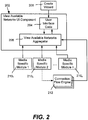
- FIG. 2 conceptually represents a user interface and architecture that makes it easier for users to connect to different networks, including by grouping separate connections into groups of networks whereby a user no longer needs to understand which connection to select when connecting to a particular network destination. For example, if a user selects a network named "work,” the underlying architecture will automatically connect the appropriate connection. This includes disconnecting other networks as necessary. For the user, the user interface changes the focus from connection (source)-based networking to destination-based networking, thus simplifying network connections.
- a view available networks component 202 includes user interface code 204 and an aggregator 206.
- the user may use a wizard 208 or the like to construct an appropriate user interface for a given computer system and the user's networks.
- the view available networks page that results is sometimes alternatively referred to as a quick connect dialog.
- the aggregator 206 pulls together the various network connection data by working with media specific modules 210 1 -210 n , such as one for wireless media, one for RAS media and so forth.
- media specific modules 210 1 -210 n such as one for wireless media, one for RAS media and so forth.
- each media type has its own media module that plugs into the aggregator 206, such as by using well-known component object model (COM) technology to connect COM objects.
- COM component object model
- each module (e.g., module 210 2 ) is associated with at least one connection flow engine 212, and there is a connection flow engine for each connection type, e.g., there is a connection flow engine for RAS, and within that connection flow engine for RAS is another connection flow engine for dialup, another for PPPoE, another for VPN, and so forth.
- the connection flow engines contain logic for performing operations and updating the aggregator 206, e.g., what actions to take when the user clicks connect, what to aggregate, how to modify the main user interface page, what actions to take when the user clicks disconnect, and so forth.
- this connection flow engine model facilitates extensibility, in that, for example, a third party vendor can supply a connection flow engine and update the user interface as a frame with new content or pages, rather than provide a separate set of dialogs for a new connection type.
- FIG. 3 exemplifies a more specific example network connect architecture
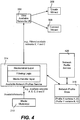
- FIG. 4 shows an available network profile service architecture for networks to which the user has previously connected or configured and wants information maintained for such networks. Note that while in general, the network connect architecture of FIG. 3 is directed towards collecting current network information and providing that information to user interface components, FIG. 3 also includes network profile concepts.
- the view available user interface component 202 is included as part of a program 302 (e.g., an operating system component) by which a user interacts with other operating system components and the like, e.g., explorer.exe in a Windows ® -based operating system as represented in FIG. 3 .
- a connect wizard 309 is represented in FIG. 3 , e.g., for connecting to previously-created network connections.
- Another set of network-related components including the media modules 310 1 and 310 2 are contained within another network service program 304, (e.g., another operating system component), e.g., svchost.exe.
- another network service program 304 e.g., another operating system component
- svchost.exe e.g., svchost.exe
- the user interface components 302 obtain information from the network service program 304 as to which networks are currently available with respect to being able to make a connection.
- the media modules are indirectly coupled to the view available networks UI component 202, e.g., via active and available network profile modules 312 and 314, respectively, to allow for filtering at this service level as to which networks are active and which are available, including those having information maintained therefor in a network profile store 316.
- the view available networks UI component 202 may be an in-process COM module, with other modules also loaded in-process.
- Each media module 310 1 -310 n may communicate with their respective services (e.g., available network COM modules 310 1 -310 n ) through some out-of-process method of their own choosing.
- FIG. 4 shows an example concept of profiles and filtering in more detail.
- the wizards and/or a user may interact with the network profile store 316 via a network profile service 420, to do things like give a friendly name to a network.
- the media modules 210 report network availability to the available network profiles service (e.g., over an IAvailableNetworks interface), where the availability information is then processed in conjunction with the network profile store data to filter out unavailable networks and/or report profiles for available networks when a network or networks for a profile are available.
- networks A-E are available, and what is filtered and reported to the view available networks UI is network C, profile X which contains networks A and D, and profile Y which contains networks B and E.
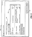
- FIG. 5 shows an exemplary user interface page 500, which along with the structure and functionality described with reference to FIG. 2-4 facilitate connections, essentially by unifying the various available networking connection into the single user interface page 500.
- the page 500 serves as a main entry point for connecting to a new or existing network.
- the UI page 500 may be built and operated using a wizard framework, e.g., comprising the create wizard 208 and connect wizard 209.
- a wizard framework allows the connection experience to flow essentially seamlessly from the view available networks UI page 500 to individual connection pages, giving a user a consistent look and feel along with a better understanding of where the user is in a given connection process.
- information on available networks may include available network profile information and data on profile constituents.
- the view available networks UI 500 may be configured to provide a single entry point for the user to view network destinations, that is, the view available networks UI page 500 may display available network profiles along with available networks. Further, as described below, the view available networks UI page 500 may be used to view subsets of this information, such as all wireless networks, all ad hoc networks, or all Wi-Max networks, and so forth.
- the view available networks UI component 202 thus provides the centralized connection UI page 500 for essentially all connections, as well as network profile types. This includes presenting users with a single interface for existing network types, as well as future types not currently implemented, (e.g., Wireless Wide Area Networking or WWAN, Wi-Max, and the like).
- the example user interface is extensible, in that third parties (e.g., independent hardware vendors, or IHVs in FIG. 3 ) may plug in new media types, and have them display as either available networks or plug into a network profile. This avoids the problem of having users learn multiple connection experiences or install / learn third party clients, instead using the same UI page 500 to simply and easily connect to networks.
- the view available networks UI page 500 provides a simple way for users to select and connect (e.g., via a button 502) to a network.
- the page 500 may display (via scrolling as necessary) all available networks profiles from the network profile store 316, such as wireless networks profiles, Ethernet connections (e.g., derived from NLAv2 signatures), RAS dial-up, VPN & CM connections, available infrastructure networks (e.g., 802.11 wireless), available ad-hoc networks (e.g., 802.11 wireless).
- Available WWAN networks may also be presented, and may correspond to data network types for GPRS, EDGE, UMTS, HSDPA, 1xRTT, 1xEV-DO, 1xEV-DV, as well as future supported data types.
- the page 500 may include additional attributes, including that that a user can easily identify a network, a user can easily identify the security status of a network, and a user can easily identify which networks are currently connected or available. Links to diagnostic and other useful information may be provided.
- the network list area 506 contains a list of all networks that were visible at the time the dialog was opened, or when list was last refreshed.
- the list area 506 may display an icon for each network, a customized network profile icon (from the profile service), a customized wireless icon (e.g., from a WISP provider), a default wireless icon (new 802.11 wireless networks), a default ad hoc wireless icon (new ad-hoc 802.11 wireless networks), a customized WWAN Icon (e.g., from a cellular provider), a customized Wi-Max icon (e.g., from a Wi-Max provider), and default icons for UWB, Bluetooth ® PAN, RAS dial-up, RAS VPN, RAS CM and/or RAS PPPoE.
- the framework allows for networks to appear or disappear via an auto-update / notification mechanism.
- the exemplified network list 506 also may display a name for each network in the list, including a network profile name (from the network profile service 316), an SSID (service set identification information) for new available 802.11 wireless networks (e.g., ad hoc / infra), the SSSID (the friendly name for WPS networks from a WISP provider), and connection names for RAS dial-up, VPN, CM & PPPoE connections.
- a network profile name from the network profile service 316
- an SSID service set identification information
- SSSID friendly name for WPS networks from a WISP provider
- connection names for RAS dial-up, VPN, CM & PPPoE connections for RAS dial-up, VPN, CM & PPPoE connections.
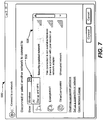
- FIG. 6 shows a subset of the available networks being displayed, e.g., the user has chosen to display only wireless connections via a drop down list 508 ( FIG. 7 ).
- the network (or networks) that is connected are displayed at the top of the list area 506, regardless of type.
- other ordering rules may be used for displaying items in the network list, such as to list networks that are in the profile store above those that are not, and for the networks in the profile store list, the order in the list is used to order the visible network list (e.g., a network higher in the profile store list appears higher in the visible network list).
- the ordering rules are decided at a media manager level, (e.g., shown as media manager module(s) 310 1 -310 n of FIG. 3 ) and then by the view available networks UI 202.
- the media manager level provides the view available networks UI 202 with an order based on defined ordering rules, which the view available networks UI 202 can reorder based upon other information, e.g., with the connected network or networks ordered to appear at the top of the list 506, but retaining the other order.
- the ordering can be performed at any level or combination of levels, including in the available network profiles service, and also may be overridden, e.g., by user preference data.
- a network is not in the profile store list, the following order may be used, namely that WPS networks that are not in the profile store list are displayed before other non-profile store list networks, and within the list of WPS networks ordering is dependent on the order the underlying AP is found and the order of the networks stored in the provisioning service (this should persist the order that was downloaded from the network, if more than one network).
- Infrastructure networks not in the preferred list are displayed before ad-hoc networks.
- ordering is dependent on the order that the wireless auto-configuration service discovers them.
- Ad-hoc networks not in the profile store list are displayed last.
- ordering is dependent on the order that the wireless auto-configuration service discovers them.
- Next (for those that are not part of a network profile) are any RAS PPPoE connections, followed by RAS CM connections, RAS VPN connections and RAS Dial-up connections.
- the security status may be displayed for each network (e.g., security enabled, unsecured) and/or other appropriate text (e.g., showing diagnostic-type information such as a capability mismatch) is displayed when not connected.
- the signal strength (if available and appropriate) of each network as is an icon for the type of connection available (e.g., VPN) as determined from the profile service.
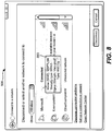
- FIG. 8 shows how additional information may be provided on hover.
- a tool tip e.g., for wireless networks, SSID, security type, radio type, signal strength, and possibly other information may be shown, whereas for WWAN, network name, signal strength, roaming status and possibly other information may be shown.
- Hovering over Wi-Max will show SSID, Security type, signal strength possibly other information
- hovering over a Bluetooth PAN network will show network name and possibly other information.
- Hovering over a VPN or dial-up may show connection name and connection duration, while an Ethernet may show adapter name, connection duration, speed, and so forth.
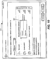
- FIGS. 9 and 10 show a right-click (or possibly keyboard initiated, left click or double-click) alternative way to connect ( FIG. 9 ) and disconnect ( FIG. 10 ) to and from a network when the mouse pointer is positioned over that network. Note that other ways of connecting and/or disconnecting from a network (e.g., via a system tray icon component 222, FIG. 2 ) are also feasible.
- the "Connect” option switches out the list of profiles to display a list of connections that are contained within the selected profile. This allows a user to connect / disconnect an individual connection. Note that in one example implementation, this only appears on network profiles and only when it contains more than one connection.
- a diagnose option may appear, such that if there is a problem with any of the connections in the profile, this option will show and when clicked will initiate diagnostics.
- a turn off Wireless option may appear, to turns off the 802.11 wireless, 802.16 (Wi-Max), WWAN, UWB, Bluetooth PAN radios.
- connection dialogs can be kept in a page, that is, in frame. This creates a consistent connection experience for the user, as the page may be modified and/or new pages can be swapped in as required. This also allows for seamless extensibility, as a third party can create a page or pages that fit into the existing flow.
Landscapes
- Engineering & Computer Science (AREA)
- Computer Networks & Wireless Communication (AREA)
- Signal Processing (AREA)
- Theoretical Computer Science (AREA)
- Human Computer Interaction (AREA)
- General Engineering & Computer Science (AREA)
- Physics & Mathematics (AREA)
- General Physics & Mathematics (AREA)
- Computer Hardware Design (AREA)
- Mathematical Physics (AREA)
- Software Systems (AREA)
- Mobile Radio Communication Systems (AREA)
- User Interface Of Digital Computer (AREA)
- Computer And Data Communications (AREA)
- Telephonic Communication Services (AREA)
- Data Exchanges In Wide-Area Networks (AREA)
Applications Claiming Priority (3)
| Application Number | Priority Date | Filing Date | Title |
|---|---|---|---|
| US71770305P | 2005-09-16 | 2005-09-16 | |
| US11/447,540 US8724484B2 (en) | 2005-09-16 | 2006-06-05 | Connecting to different network types through a common user interface |
| PCT/US2006/035648 WO2007035352A1 (en) | 2005-09-16 | 2006-09-13 | Connecting to different network types through a common user interface |
Publications (3)
| Publication Number | Publication Date |
|---|---|
| EP1925121A1 EP1925121A1 (en) | 2008-05-28 |
| EP1925121A4 EP1925121A4 (en) | 2011-03-09 |
| EP1925121B1 true EP1925121B1 (en) | 2017-03-15 |
Family
ID=37885508
Family Applications (1)
| Application Number | Title | Priority Date | Filing Date |
|---|---|---|---|
| EP06814579.6A Not-in-force EP1925121B1 (en) | 2005-09-16 | 2006-09-13 | Connecting to different network types through a common user interface |
Country Status (9)
| Country | Link |
|---|---|
| US (3) | US8724484B2 (enExample) |
| EP (1) | EP1925121B1 (enExample) |
| JP (1) | JP5318575B2 (enExample) |
| KR (1) | KR101376849B1 (enExample) |
| AU (1) | AU2006292617B2 (enExample) |
| BR (1) | BRPI0616234A8 (enExample) |
| CA (1) | CA2622645C (enExample) |
| RU (1) | RU2428802C2 (enExample) |
| WO (1) | WO2007035352A1 (enExample) |
Families Citing this family (32)
| Publication number | Priority date | Publication date | Assignee | Title |
|---|---|---|---|---|
| US7812856B2 (en) | 2000-10-26 | 2010-10-12 | Front Row Technologies, Llc | Providing multiple perspectives of a venue activity to electronic wireless hand held devices |
| US7630721B2 (en) | 2000-06-27 | 2009-12-08 | Ortiz & Associates Consulting, Llc | Systems, methods and apparatuses for brokering data between wireless devices and data rendering devices |
| US8724484B2 (en) | 2005-09-16 | 2014-05-13 | Microsoft Corporation | Connecting to different network types through a common user interface |
| EP2059061B1 (en) * | 2006-08-23 | 2014-07-23 | NEC Corporation | Mobile communication system, radio network control device, mobile telephone, and cell display method |
| CA2607823C (en) * | 2006-10-26 | 2014-07-29 | Research In Motion Limited | Transient wlan connection profiles |
| WO2008061347A1 (en) * | 2006-11-21 | 2008-05-29 | Research In Motion Limited | Displaying a list of available wireless local area networks |
| US8040820B2 (en) * | 2007-03-06 | 2011-10-18 | Cisco Technology, Inc. | Modelling service flows in dynamic access domains |
| US8533345B2 (en) * | 2007-05-08 | 2013-09-10 | Blackberry Limited | System and method for managing connections for networks used by a communication device |
| US20090240814A1 (en) * | 2008-03-18 | 2009-09-24 | Microsoft Corporation | Unified pairing for wireless devices |
| US8238238B2 (en) * | 2008-05-16 | 2012-08-07 | Microsoft Corporation | Performing networking tasks based on destination networks |
| US7783803B2 (en) * | 2008-11-03 | 2010-08-24 | Microsoft Corporation | Pairing service technologies |
| US8676942B2 (en) * | 2008-11-21 | 2014-03-18 | Microsoft Corporation | Common configuration application programming interface |
| US8683046B2 (en) * | 2008-11-21 | 2014-03-25 | Microsoft Corporation | Unified interface for configuring multiple networking technologies |
| US8615570B2 (en) * | 2008-11-21 | 2013-12-24 | Microsoft Corporation | Unified storage for configuring multiple networking technologies |
| US8751612B2 (en) * | 2008-11-21 | 2014-06-10 | Microsoft Corporation | Creating cross-technology configuration settings |
| US9760916B1 (en) * | 2009-05-20 | 2017-09-12 | Photobucket Corporation | Methods and systems for internet distribution of aggregated media actions |
| JP5608692B2 (ja) | 2011-02-17 | 2014-10-15 | パナソニック株式会社 | ネットワーク接続装置および方法 |
| US9668196B2 (en) * | 2013-01-29 | 2017-05-30 | Cooper Technologies Company | Network administrator interface systems and methods for monitoring industrial wireless, self-organizing mesh communication networks |
| US9258298B2 (en) | 2013-03-04 | 2016-02-09 | Arris Enterprises, Inc. | Simplified configuration of a network device |
| US9629004B2 (en) | 2014-10-17 | 2017-04-18 | Microsoft Technology Licensing, Llc | Indication of wireless signal quality using detected errors in data |
| CN104320830B (zh) * | 2014-10-20 | 2018-09-04 | 小米科技有限责任公司 | 无线设备列表的显示方法和装置、无线设备及其广播方法 |
| US10630773B2 (en) * | 2015-11-12 | 2020-04-21 | Nvidia Corporation | System and method for network coupled cloud gaming |
| US11027199B2 (en) | 2015-11-12 | 2021-06-08 | Nvidia Corporation | System and method for network coupled gaming |
| US9998912B2 (en) | 2016-03-25 | 2018-06-12 | International Business Machines Corporation | Policy-driven aggregated network data use in mobile devices |
| US9860736B1 (en) * | 2016-09-30 | 2018-01-02 | Microsoft Technology Licensing, Llc | Providing network resource access based on a purpose identifier |
| US12041693B2 (en) | 2019-07-12 | 2024-07-16 | Lg Electronics Inc. | Network ID information processing |
| CN114980042A (zh) * | 2021-02-20 | 2022-08-30 | 深圳市万普拉斯科技有限公司 | 蓝牙通信方法、装置、计算机设备和存储介质 |
| CN115061611B (zh) * | 2021-02-27 | 2025-05-23 | 华为技术有限公司 | 一种菜单列表更新方法和电子设备 |
| US11418582B1 (en) * | 2021-07-06 | 2022-08-16 | Citrix Systems, Inc. | Priority-based transport connection control |
| US11875015B2 (en) | 2022-04-13 | 2024-01-16 | Truist Bank | Access card with configurable transaction rules |
| US11770330B1 (en) | 2022-04-13 | 2023-09-26 | Truist Bank | Automatically routing network requests between computer subsystems |
| US11550450B1 (en) * | 2022-04-13 | 2023-01-10 | Truist Bank | Graphical user interface for configuring card controls for a card |
Family Cites Families (33)
| Publication number | Priority date | Publication date | Assignee | Title |
|---|---|---|---|---|
| EP0138535A3 (en) | 1983-10-13 | 1987-01-28 | British Telecommunications Plc | Visual display logic simulation system |
| US6212529B1 (en) | 1996-11-13 | 2001-04-03 | Puma Technology, Inc. | Synchronization of databases using filters |
| US6295556B1 (en) | 1997-11-18 | 2001-09-25 | Microsoft Corporation | Method and system for configuring computers to connect to networks using network connection objects |
| US7313806B1 (en) * | 1998-10-30 | 2007-12-25 | Intel Corporation | Method and apparatus for channel surfing through multiple sources based on user-definable preferences |
| US6587433B1 (en) * | 1998-11-25 | 2003-07-01 | 3Com Corporation | Remote access server for multiple service classes in IP networks |
| JP2000259312A (ja) | 1999-03-11 | 2000-09-22 | Seiko Epson Corp | ファイル一覧表示ユーザインタフェース |
| US6647409B1 (en) | 1999-07-13 | 2003-11-11 | Microsoft Corporation | Maintaining a sliding view of server based data on a handheld personal computer |
| US6665720B1 (en) | 1999-09-21 | 2003-12-16 | Intel Corporation | Adapter for a home power line network |
| US7392309B2 (en) * | 1999-10-27 | 2008-06-24 | American Power Conversion Corporation | Network appliance management |
| US6965948B1 (en) | 1999-11-12 | 2005-11-15 | Telefonaktiebolaget Lm Ericsson (Publ) | Method and apparatus for selective network access |
| US7120129B2 (en) * | 2001-03-13 | 2006-10-10 | Microsoft Corporation | System and method for achieving zero-configuration wireless computing and computing device incorporating same |
| ATE433628T1 (de) * | 2001-07-10 | 2009-06-15 | Koninkl Philips Electronics Nv | Gateway zur verbindung von netzen |
| US20040003060A1 (en) * | 2001-07-13 | 2004-01-01 | International Business Machines Corporation | Method and apparatus for network connection registration and selection |
| US6801777B2 (en) | 2001-11-27 | 2004-10-05 | Intel Corporation | Device and method for intelligent wireless communication selection |
| US7483984B1 (en) * | 2001-12-19 | 2009-01-27 | Boingo Wireless, Inc. | Method and apparatus for accessing networks by a mobile device |
| US20030172118A1 (en) | 2002-03-05 | 2003-09-11 | International Business Machines Corporation | Method and apparatus for providing post office protocol 3 support for limited storage devices |
| US20040019665A1 (en) * | 2002-07-24 | 2004-01-29 | Liang Thomas T. | Logging mobile devices onto multiple networks |
| JP2004094736A (ja) | 2002-09-02 | 2004-03-25 | Toshiba Corp | 電子機器、通信環境設定方法およびプログラム |
| JP2006502678A (ja) | 2002-10-02 | 2006-01-19 | コーニンクレッカ フィリップス エレクトロニクス エヌ ヴィ | 携帯用装置のスマート接続の管理 |
| US7599323B2 (en) * | 2002-10-17 | 2009-10-06 | Alcatel-Lucent Usa Inc. | Multi-interface mobility client |
| JP2004214934A (ja) | 2002-12-27 | 2004-07-29 | Matsushita Electric Ind Co Ltd | プレゼンス情報処理端末及びプレゼンス情報処理用プログラム並びにプレゼンスサービス提供サーバ |
| JP2004272563A (ja) | 2003-03-07 | 2004-09-30 | Fujitsu Ltd | 通信制御プログラム、コンテンツ配信プログラム、端末装置、およびコンテンツサーバ |
| US7127235B2 (en) | 2003-04-30 | 2006-10-24 | Hewlett-Packard Development Company, L.P. | Multiple protocol database |
| WO2005039112A1 (en) | 2003-10-16 | 2005-04-28 | Koninklijke Philips Electronics, N.V. | Automated network selection and association |
| US7996505B2 (en) | 2003-10-24 | 2011-08-09 | Microsoft Corporation | Network and interface selection on a computing device capable of establishing connections via multiple network communications media |
| JP2005176021A (ja) * | 2003-12-12 | 2005-06-30 | Toshiba Corp | 情報処理装置およびプログラム |
| CN1630234A (zh) | 2003-12-19 | 2005-06-22 | 英业达股份有限公司 | 可切换式无线网络连接方法及系统 |
| US8332943B2 (en) * | 2004-02-17 | 2012-12-11 | Microsoft Corporation | Tiered object-related trust decisions |
| US8005476B2 (en) * | 2004-04-16 | 2011-08-23 | Broadcom Corporation | Providing access dependent services via a broadband access gateway |
| US7469139B2 (en) * | 2004-05-24 | 2008-12-23 | Computer Associates Think, Inc. | Wireless manager and method for configuring and securing wireless access to a network |
| US8316438B1 (en) * | 2004-08-10 | 2012-11-20 | Pure Networks Llc | Network management providing network health information and lockdown security |
| US8478849B2 (en) * | 2004-12-07 | 2013-07-02 | Pure Networks LLC. | Network administration tool |
| US8724484B2 (en) | 2005-09-16 | 2014-05-13 | Microsoft Corporation | Connecting to different network types through a common user interface |
-
2006
- 2006-06-05 US US11/447,540 patent/US8724484B2/en active Active
- 2006-09-13 CA CA2622645A patent/CA2622645C/en active Active
- 2006-09-13 EP EP06814579.6A patent/EP1925121B1/en not_active Not-in-force
- 2006-09-13 JP JP2008531274A patent/JP5318575B2/ja not_active Expired - Fee Related
- 2006-09-13 KR KR1020087006303A patent/KR101376849B1/ko active Active
- 2006-09-13 BR BRPI0616234A patent/BRPI0616234A8/pt active Search and Examination
- 2006-09-13 RU RU2008110051/09A patent/RU2428802C2/ru active
- 2006-09-13 WO PCT/US2006/035648 patent/WO2007035352A1/en not_active Ceased
- 2006-09-13 AU AU2006292617A patent/AU2006292617B2/en not_active Ceased
-
2014
- 2014-05-09 US US14/273,803 patent/US9762448B2/en not_active Expired - Fee Related
-
2017
- 2017-05-23 US US15/603,346 patent/US20170257278A1/en not_active Abandoned
Non-Patent Citations (1)
| Title |
|---|
| None * |
Also Published As
| Publication number | Publication date |
|---|---|
| RU2428802C2 (ru) | 2011-09-10 |
| EP1925121A1 (en) | 2008-05-28 |
| US20070067446A1 (en) | 2007-03-22 |
| US20170257278A1 (en) | 2017-09-07 |
| US8724484B2 (en) | 2014-05-13 |
| US20140310602A1 (en) | 2014-10-16 |
| WO2007035352A1 (en) | 2007-03-29 |
| BRPI0616234A8 (pt) | 2016-11-16 |
| KR20080055836A (ko) | 2008-06-19 |
| RU2008110051A (ru) | 2009-09-20 |
| JP5318575B2 (ja) | 2013-10-16 |
| BRPI0616234A2 (pt) | 2011-06-14 |
| AU2006292617A1 (en) | 2007-03-29 |
| CA2622645A1 (en) | 2007-03-29 |
| EP1925121A4 (en) | 2011-03-09 |
| JP2009509241A (ja) | 2009-03-05 |
| CA2622645C (en) | 2015-05-05 |
| KR101376849B1 (ko) | 2014-03-27 |
| AU2006292617B2 (en) | 2010-05-13 |
| US9762448B2 (en) | 2017-09-12 |
Similar Documents
| Publication | Publication Date | Title |
|---|---|---|
| EP1925121B1 (en) | Connecting to different network types through a common user interface | |
| EP1810416B1 (en) | System and method for managing wireless connections in computer | |
| US20130326356A9 (en) | System and method for managing wireless connections in computer | |
| CN103988161B (zh) | 用于调整应用的屏幕流的方法和系统 | |
| US7631270B2 (en) | Network connectivity and wireless status in a notification area | |
| US20070201384A1 (en) | Network explorer | |
| US20100199201A1 (en) | System and method for displaying a display panel | |
| US20060161848A1 (en) | Start menu user tiles | |
| CN101263683A (zh) | 通过通用用户界面连接至不同的网络类型 | |
| JP2007334633A (ja) | リモートデスクトップシステム | |
| US20030115306A1 (en) | Modification of map of storage area network resources | |
| CN101057414A (zh) | 用于管理计算机中的无线连接的系统和方法 | |
| JP2019016211A (ja) | 監視装置および監視方法 |
Legal Events
| Date | Code | Title | Description |
|---|---|---|---|
| PUAI | Public reference made under article 153(3) epc to a published international application that has entered the european phase |
Free format text: ORIGINAL CODE: 0009012 |
|
| 17P | Request for examination filed |
Effective date: 20080305 |
|
| AK | Designated contracting states |
Kind code of ref document: A1 Designated state(s): AT BE BG CH CY CZ DE DK EE ES FI FR GB GR HU IE IS IT LI LT LU LV MC NL PL PT RO SE SI SK TR |
|
| A4 | Supplementary search report drawn up and despatched |
Effective date: 20110203 |
|
| RIC1 | Information provided on ipc code assigned before grant |
Ipc: H04L 29/08 20060101ALI20110128BHEP Ipc: H04L 12/24 20060101AFI20070601BHEP Ipc: H04L 12/56 20060101ALI20110128BHEP |
|
| DAX | Request for extension of the european patent (deleted) | ||
| 17Q | First examination report despatched |
Effective date: 20140428 |
|
| RAP1 | Party data changed (applicant data changed or rights of an application transferred) |
Owner name: MICROSOFT TECHNOLOGY LICENSING, LLC |
|
| GRAP | Despatch of communication of intention to grant a patent |
Free format text: ORIGINAL CODE: EPIDOSNIGR1 |
|
| RIC1 | Information provided on ipc code assigned before grant |
Ipc: G06F 3/0482 20130101ALI20160922BHEP Ipc: H04L 12/24 20060101AFI20160922BHEP Ipc: H04L 29/08 20060101ALI20160922BHEP Ipc: H04L 12/54 20060101ALI20160922BHEP |
|
| INTG | Intention to grant announced |
Effective date: 20161007 |
|
| GRAS | Grant fee paid |
Free format text: ORIGINAL CODE: EPIDOSNIGR3 |
|
| GRAA | (expected) grant |
Free format text: ORIGINAL CODE: 0009210 |
|
| AK | Designated contracting states |
Kind code of ref document: B1 Designated state(s): AT BE BG CH CY CZ DE DK EE ES FI FR GB GR HU IE IS IT LI LT LU LV MC NL PL PT RO SE SI SK TR |
|
| REG | Reference to a national code |
Ref country code: CH Ref legal event code: EP Ref country code: GB Ref legal event code: FG4D |
|
| REG | Reference to a national code |
Ref country code: IE Ref legal event code: FG4D |
|
| REG | Reference to a national code |
Ref country code: AT Ref legal event code: REF Ref document number: 876569 Country of ref document: AT Kind code of ref document: T Effective date: 20170415 |
|
| REG | Reference to a national code |
Ref country code: NL Ref legal event code: FP |
|
| REG | Reference to a national code |
Ref country code: DE Ref legal event code: R096 Ref document number: 602006051988 Country of ref document: DE |
|
| REG | Reference to a national code |
Ref country code: LT Ref legal event code: MG4D |
|
| PG25 | Lapsed in a contracting state [announced via postgrant information from national office to epo] |
Ref country code: GR Free format text: LAPSE BECAUSE OF FAILURE TO SUBMIT A TRANSLATION OF THE DESCRIPTION OR TO PAY THE FEE WITHIN THE PRESCRIBED TIME-LIMIT Effective date: 20170616 Ref country code: FI Free format text: LAPSE BECAUSE OF FAILURE TO SUBMIT A TRANSLATION OF THE DESCRIPTION OR TO PAY THE FEE WITHIN THE PRESCRIBED TIME-LIMIT Effective date: 20170315 Ref country code: LT Free format text: LAPSE BECAUSE OF FAILURE TO SUBMIT A TRANSLATION OF THE DESCRIPTION OR TO PAY THE FEE WITHIN THE PRESCRIBED TIME-LIMIT Effective date: 20170315 |
|
| REG | Reference to a national code |
Ref country code: FR Ref legal event code: PLFP Year of fee payment: 12 |
|
| REG | Reference to a national code |
Ref country code: AT Ref legal event code: MK05 Ref document number: 876569 Country of ref document: AT Kind code of ref document: T Effective date: 20170315 |
|
| PG25 | Lapsed in a contracting state [announced via postgrant information from national office to epo] |
Ref country code: BG Free format text: LAPSE BECAUSE OF FAILURE TO SUBMIT A TRANSLATION OF THE DESCRIPTION OR TO PAY THE FEE WITHIN THE PRESCRIBED TIME-LIMIT Effective date: 20170615 Ref country code: SE Free format text: LAPSE BECAUSE OF FAILURE TO SUBMIT A TRANSLATION OF THE DESCRIPTION OR TO PAY THE FEE WITHIN THE PRESCRIBED TIME-LIMIT Effective date: 20170315 Ref country code: LV Free format text: LAPSE BECAUSE OF FAILURE TO SUBMIT A TRANSLATION OF THE DESCRIPTION OR TO PAY THE FEE WITHIN THE PRESCRIBED TIME-LIMIT Effective date: 20170315 |
|
| PG25 | Lapsed in a contracting state [announced via postgrant information from national office to epo] |
Ref country code: RO Free format text: LAPSE BECAUSE OF FAILURE TO SUBMIT A TRANSLATION OF THE DESCRIPTION OR TO PAY THE FEE WITHIN THE PRESCRIBED TIME-LIMIT Effective date: 20170315 Ref country code: CZ Free format text: LAPSE BECAUSE OF FAILURE TO SUBMIT A TRANSLATION OF THE DESCRIPTION OR TO PAY THE FEE WITHIN THE PRESCRIBED TIME-LIMIT Effective date: 20170315 Ref country code: ES Free format text: LAPSE BECAUSE OF FAILURE TO SUBMIT A TRANSLATION OF THE DESCRIPTION OR TO PAY THE FEE WITHIN THE PRESCRIBED TIME-LIMIT Effective date: 20170315 Ref country code: EE Free format text: LAPSE BECAUSE OF FAILURE TO SUBMIT A TRANSLATION OF THE DESCRIPTION OR TO PAY THE FEE WITHIN THE PRESCRIBED TIME-LIMIT Effective date: 20170315 Ref country code: SK Free format text: LAPSE BECAUSE OF FAILURE TO SUBMIT A TRANSLATION OF THE DESCRIPTION OR TO PAY THE FEE WITHIN THE PRESCRIBED TIME-LIMIT Effective date: 20170315 Ref country code: AT Free format text: LAPSE BECAUSE OF FAILURE TO SUBMIT A TRANSLATION OF THE DESCRIPTION OR TO PAY THE FEE WITHIN THE PRESCRIBED TIME-LIMIT Effective date: 20170315 Ref country code: IT Free format text: LAPSE BECAUSE OF FAILURE TO SUBMIT A TRANSLATION OF THE DESCRIPTION OR TO PAY THE FEE WITHIN THE PRESCRIBED TIME-LIMIT Effective date: 20170315 |
|
| PG25 | Lapsed in a contracting state [announced via postgrant information from national office to epo] |
Ref country code: PL Free format text: LAPSE BECAUSE OF FAILURE TO SUBMIT A TRANSLATION OF THE DESCRIPTION OR TO PAY THE FEE WITHIN THE PRESCRIBED TIME-LIMIT Effective date: 20170315 Ref country code: PT Free format text: LAPSE BECAUSE OF FAILURE TO SUBMIT A TRANSLATION OF THE DESCRIPTION OR TO PAY THE FEE WITHIN THE PRESCRIBED TIME-LIMIT Effective date: 20170717 Ref country code: IS Free format text: LAPSE BECAUSE OF FAILURE TO SUBMIT A TRANSLATION OF THE DESCRIPTION OR TO PAY THE FEE WITHIN THE PRESCRIBED TIME-LIMIT Effective date: 20170715 |
|
| REG | Reference to a national code |
Ref country code: DE Ref legal event code: R097 Ref document number: 602006051988 Country of ref document: DE |
|
| PLBE | No opposition filed within time limit |
Free format text: ORIGINAL CODE: 0009261 |
|
| STAA | Information on the status of an ep patent application or granted ep patent |
Free format text: STATUS: NO OPPOSITION FILED WITHIN TIME LIMIT |
|
| PG25 | Lapsed in a contracting state [announced via postgrant information from national office to epo] |
Ref country code: DK Free format text: LAPSE BECAUSE OF FAILURE TO SUBMIT A TRANSLATION OF THE DESCRIPTION OR TO PAY THE FEE WITHIN THE PRESCRIBED TIME-LIMIT Effective date: 20170315 |
|
| 26N | No opposition filed |
Effective date: 20171218 |
|
| PG25 | Lapsed in a contracting state [announced via postgrant information from national office to epo] |
Ref country code: SI Free format text: LAPSE BECAUSE OF FAILURE TO SUBMIT A TRANSLATION OF THE DESCRIPTION OR TO PAY THE FEE WITHIN THE PRESCRIBED TIME-LIMIT Effective date: 20170315 |
|
| REG | Reference to a national code |
Ref country code: CH Ref legal event code: PL |
|
| PG25 | Lapsed in a contracting state [announced via postgrant information from national office to epo] |
Ref country code: MC Free format text: LAPSE BECAUSE OF FAILURE TO SUBMIT A TRANSLATION OF THE DESCRIPTION OR TO PAY THE FEE WITHIN THE PRESCRIBED TIME-LIMIT Effective date: 20170315 |
|
| REG | Reference to a national code |
Ref country code: IE Ref legal event code: MM4A |
|
| REG | Reference to a national code |
Ref country code: BE Ref legal event code: MM Effective date: 20170930 |
|
| PG25 | Lapsed in a contracting state [announced via postgrant information from national office to epo] |
Ref country code: LU Free format text: LAPSE BECAUSE OF NON-PAYMENT OF DUE FEES Effective date: 20170913 |
|
| PG25 | Lapsed in a contracting state [announced via postgrant information from national office to epo] |
Ref country code: IE Free format text: LAPSE BECAUSE OF NON-PAYMENT OF DUE FEES Effective date: 20170913 Ref country code: LI Free format text: LAPSE BECAUSE OF NON-PAYMENT OF DUE FEES Effective date: 20170930 Ref country code: CH Free format text: LAPSE BECAUSE OF NON-PAYMENT OF DUE FEES Effective date: 20170930 |
|
| REG | Reference to a national code |
Ref country code: FR Ref legal event code: PLFP Year of fee payment: 13 |
|
| PG25 | Lapsed in a contracting state [announced via postgrant information from national office to epo] |
Ref country code: BE Free format text: LAPSE BECAUSE OF NON-PAYMENT OF DUE FEES Effective date: 20170930 |
|
| PG25 | Lapsed in a contracting state [announced via postgrant information from national office to epo] |
Ref country code: HU Free format text: LAPSE BECAUSE OF FAILURE TO SUBMIT A TRANSLATION OF THE DESCRIPTION OR TO PAY THE FEE WITHIN THE PRESCRIBED TIME-LIMIT; INVALID AB INITIO Effective date: 20060913 |
|
| PG25 | Lapsed in a contracting state [announced via postgrant information from national office to epo] |
Ref country code: CY Free format text: LAPSE BECAUSE OF NON-PAYMENT OF DUE FEES Effective date: 20170315 |
|
| PG25 | Lapsed in a contracting state [announced via postgrant information from national office to epo] |
Ref country code: TR Free format text: LAPSE BECAUSE OF FAILURE TO SUBMIT A TRANSLATION OF THE DESCRIPTION OR TO PAY THE FEE WITHIN THE PRESCRIBED TIME-LIMIT Effective date: 20170315 |
|
| REG | Reference to a national code |
Ref country code: DE Ref legal event code: R079 Ref document number: 602006051988 Country of ref document: DE Free format text: PREVIOUS MAIN CLASS: H04L0012240000 Ipc: H04L0041000000 |
|
| P01 | Opt-out of the competence of the unified patent court (upc) registered |
Effective date: 20230512 |
|
| PGFP | Annual fee paid to national office [announced via postgrant information from national office to epo] |
Ref country code: NL Payment date: 20230822 Year of fee payment: 18 |
|
| PGFP | Annual fee paid to national office [announced via postgrant information from national office to epo] |
Ref country code: GB Payment date: 20230823 Year of fee payment: 18 |
|
| PGFP | Annual fee paid to national office [announced via postgrant information from national office to epo] |
Ref country code: FR Payment date: 20230822 Year of fee payment: 18 Ref country code: DE Payment date: 20230822 Year of fee payment: 18 |
|
| REG | Reference to a national code |
Ref country code: DE Ref legal event code: R119 Ref document number: 602006051988 Country of ref document: DE |
|
| REG | Reference to a national code |
Ref country code: NL Ref legal event code: MM Effective date: 20241001 |
|
| GBPC | Gb: european patent ceased through non-payment of renewal fee |
Effective date: 20240913 |
|
| PG25 | Lapsed in a contracting state [announced via postgrant information from national office to epo] |
Ref country code: NL Free format text: LAPSE BECAUSE OF NON-PAYMENT OF DUE FEES Effective date: 20241001 |
|
| PG25 | Lapsed in a contracting state [announced via postgrant information from national office to epo] |
Ref country code: DE Free format text: LAPSE BECAUSE OF NON-PAYMENT OF DUE FEES Effective date: 20250401 |
|
| PG25 | Lapsed in a contracting state [announced via postgrant information from national office to epo] |
Ref country code: GB Free format text: LAPSE BECAUSE OF NON-PAYMENT OF DUE FEES Effective date: 20240913 |
|
| PG25 | Lapsed in a contracting state [announced via postgrant information from national office to epo] |
Ref country code: FR Free format text: LAPSE BECAUSE OF NON-PAYMENT OF DUE FEES Effective date: 20240930 |