EP1923883A2 - Aufnahme- und Wiedergabevorrichtung für eine optische Platte - Google Patents
Aufnahme- und Wiedergabevorrichtung für eine optische Platte Download PDFInfo
- Publication number
- EP1923883A2 EP1923883A2 EP07021840A EP07021840A EP1923883A2 EP 1923883 A2 EP1923883 A2 EP 1923883A2 EP 07021840 A EP07021840 A EP 07021840A EP 07021840 A EP07021840 A EP 07021840A EP 1923883 A2 EP1923883 A2 EP 1923883A2
- Authority
- EP
- European Patent Office
- Prior art keywords
- power failure
- failure recovery
- optical disc
- interruption
- recording
- Prior art date
- Legal status (The legal status is an assumption and is not a legal conclusion. Google has not performed a legal analysis and makes no representation as to the accuracy of the status listed.)
- Granted
Links
- 230000003287 optical effect Effects 0.000 title claims abstract description 56
- 238000011084 recovery Methods 0.000 claims abstract description 127
- 238000000034 method Methods 0.000 claims abstract description 30
- 238000000926 separation method Methods 0.000 description 4
- 230000005236 sound signal Effects 0.000 description 4
- 230000001627 detrimental effect Effects 0.000 description 2
- 238000010586 diagram Methods 0.000 description 2
- 101100018408 Arabidopsis thaliana IDN2 gene Proteins 0.000 description 1
- 101001107782 Homo sapiens Iron-sulfur protein NUBPL Proteins 0.000 description 1
- 102100021998 Iron-sulfur protein NUBPL Human genes 0.000 description 1
- 101100072620 Streptomyces griseus ind2 gene Proteins 0.000 description 1
- 238000005516 engineering process Methods 0.000 description 1
- 230000006870 function Effects 0.000 description 1
- 230000002035 prolonged effect Effects 0.000 description 1
- 230000002194 synthesizing effect Effects 0.000 description 1
- 230000000007 visual effect Effects 0.000 description 1
Images


Classifications
-
- G—PHYSICS
- G11—INFORMATION STORAGE
- G11B—INFORMATION STORAGE BASED ON RELATIVE MOVEMENT BETWEEN RECORD CARRIER AND TRANSDUCER
- G11B27/00—Editing; Indexing; Addressing; Timing or synchronising; Monitoring; Measuring tape travel
- G11B27/36—Monitoring, i.e. supervising the progress of recording or reproducing
-
- G—PHYSICS
- G11—INFORMATION STORAGE
- G11B—INFORMATION STORAGE BASED ON RELATIVE MOVEMENT BETWEEN RECORD CARRIER AND TRANSDUCER
- G11B19/00—Driving, starting, stopping record carriers not specifically of filamentary or web form, or of supports therefor; Control thereof; Control of operating function ; Driving both disc and head
- G11B19/02—Control of operating function, e.g. switching from recording to reproducing
- G11B19/16—Manual control
-
- H—ELECTRICITY
- H04—ELECTRIC COMMUNICATION TECHNIQUE
- H04N—PICTORIAL COMMUNICATION, e.g. TELEVISION
- H04N21/00—Selective content distribution, e.g. interactive television or video on demand [VOD]
- H04N21/40—Client devices specifically adapted for the reception of or interaction with content, e.g. set-top-box [STB]; Operations thereof
- H04N21/41—Structure of client; Structure of client peripherals
- H04N21/426—Internal components of the client ; Characteristics thereof
- H04N21/42646—Internal components of the client ; Characteristics thereof for reading from or writing on a non-volatile solid state storage medium, e.g. DVD, CD-ROM
-
- H—ELECTRICITY
- H04—ELECTRIC COMMUNICATION TECHNIQUE
- H04N—PICTORIAL COMMUNICATION, e.g. TELEVISION
- H04N21/00—Selective content distribution, e.g. interactive television or video on demand [VOD]
- H04N21/40—Client devices specifically adapted for the reception of or interaction with content, e.g. set-top-box [STB]; Operations thereof
- H04N21/43—Processing of content or additional data, e.g. demultiplexing additional data from a digital video stream; Elementary client operations, e.g. monitoring of home network or synchronising decoder's clock; Client middleware
- H04N21/442—Monitoring of processes or resources, e.g. detecting the failure of a recording device, monitoring the downstream bandwidth, the number of times a movie has been viewed, the storage space available from the internal hard disk
- H04N21/4425—Monitoring of client processing errors or hardware failure
-
- H—ELECTRICITY
- H04—ELECTRIC COMMUNICATION TECHNIQUE
- H04N—PICTORIAL COMMUNICATION, e.g. TELEVISION
- H04N21/00—Selective content distribution, e.g. interactive television or video on demand [VOD]
- H04N21/40—Client devices specifically adapted for the reception of or interaction with content, e.g. set-top-box [STB]; Operations thereof
- H04N21/43—Processing of content or additional data, e.g. demultiplexing additional data from a digital video stream; Elementary client operations, e.g. monitoring of home network or synchronising decoder's clock; Client middleware
- H04N21/443—OS processes, e.g. booting an STB, implementing a Java virtual machine in an STB or power management in an STB
- H04N21/4432—Powering on the client, e.g. bootstrap loading using setup parameters being stored locally or received from the server
-
- H—ELECTRICITY
- H04—ELECTRIC COMMUNICATION TECHNIQUE
- H04N—PICTORIAL COMMUNICATION, e.g. TELEVISION
- H04N21/00—Selective content distribution, e.g. interactive television or video on demand [VOD]
- H04N21/40—Client devices specifically adapted for the reception of or interaction with content, e.g. set-top-box [STB]; Operations thereof
- H04N21/47—End-user applications
- H04N21/488—Data services, e.g. news ticker
- H04N21/4882—Data services, e.g. news ticker for displaying messages, e.g. warnings, reminders
-
- H—ELECTRICITY
- H04—ELECTRIC COMMUNICATION TECHNIQUE
- H04N—PICTORIAL COMMUNICATION, e.g. TELEVISION
- H04N5/00—Details of television systems
- H04N5/76—Television signal recording
- H04N5/84—Television signal recording using optical recording
- H04N5/85—Television signal recording using optical recording on discs or drums
-
- H—ELECTRICITY
- H04—ELECTRIC COMMUNICATION TECHNIQUE
- H04N—PICTORIAL COMMUNICATION, e.g. TELEVISION
- H04N9/00—Details of colour television systems
- H04N9/79—Processing of colour television signals in connection with recording
- H04N9/80—Transformation of the television signal for recording, e.g. modulation, frequency changing; Inverse transformation for playback
- H04N9/804—Transformation of the television signal for recording, e.g. modulation, frequency changing; Inverse transformation for playback involving pulse code modulation of the colour picture signal components
- H04N9/8042—Transformation of the television signal for recording, e.g. modulation, frequency changing; Inverse transformation for playback involving pulse code modulation of the colour picture signal components involving data reduction
-
- G—PHYSICS
- G11—INFORMATION STORAGE
- G11B—INFORMATION STORAGE BASED ON RELATIVE MOVEMENT BETWEEN RECORD CARRIER AND TRANSDUCER
- G11B19/00—Driving, starting, stopping record carriers not specifically of filamentary or web form, or of supports therefor; Control thereof; Control of operating function ; Driving both disc and head
- G11B19/02—Control of operating function, e.g. switching from recording to reproducing
- G11B19/04—Arrangements for preventing, inhibiting, or warning against double recording on the same blank or against other recording or reproducing malfunctions
- G11B19/047—Recovery from power failure
Definitions
- the present invention relates to an optical disc recording and reproducing apparatus for recording and reproducing information to and from an optical disc, and particularly relates to an optical disc recording and reproducing apparatus having a function capable of interrupting a power failure recovery process when a power failure occurs during recording.
- DVDs Digital Versatile Discs
- DVD-ROMs where information is recorded on the manufacturer side and cannot be over-written on the user side
- DVD-Rs or DVD+Rs where information can be recorded one time on the user side
- DVD-RWs, DVD+RWs or DVD-RAM etc. where information can be re-written any number of times on the user side.
- the information recorded on these DVDs can be reproduced by an optical disc reproducing apparatus (a DVD player) or an optical disc recording and reproducing apparatus (DVD recorder). Recording of information to a DVD-R, DWD+R, DVD-RW, DVD+RW, and DVD-RAM is possible using an optical disc recording and reproducing apparatus (DVD recorder).
- a predetermined number of retries take place for an address that cannot be written to.
- that address is skipped and recording of data to a subsequent address is then attempted.
- this address is skipped and it is attempted to read data from a subsequent address.
- the configuration is such that the power failure recovery process is entered again when the power is turned on again as a result of a normal power key operation even after the power supply is turned off as a result of a normal power key operation or as a result of a power plug of the apparatus being removed from a power outlet once the apparatus enters the power failure recovery process.
- JP-A-2006-134142 of the related art discloses a technology where, when it is detected that power is no longer being supplied as a result of a power failure, etc, an automatic completion process is carried out where the power required to carry out the automatic completion process is supplied by a back-up power supply apparatus and the power is turned off after the automatic completion process is complete.
- a back-up power supply apparatus the power required to carry out the automatic completion process is supplied by a back-up power supply apparatus and the power is turned off after the automatic completion process is complete.
- a secondary battery contained in the back-up power supply apparatus was not charged sufficiently.
- the secondary battery deteriorates so that there is no longer any electrical power stored, it is not possible to carry out the automatic completion process. In this case, after the power supply is recovered, it is necessary to carry out the power failure recovery process described above.
- the optical disc recording and reproducing apparatus invites increases in costs, and it is necessary to provide sufficient space for providing the back-up power supply apparatus. This also means that the casing of the apparatus becomes larger.
- the system controller while performing a power failure recovery process when a power supply goes off due to a power failure and is turned on again, carries out a power failure recovery interruption process to interrupt the power failure recovery process when a specific key operation is received.
- the system controller also accepts user operations as normal after completion of the power failure recovery interruption process so as to allow processing corresponding to the user operations to be executed.
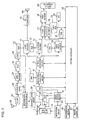
- FIG. 1 is a block diagram showing the structure of an optical disc recording and reproducing apparatus taken as a DVD recorder according to an embodiment of the present invention.
- this DVD recorder is provided with: a system controller 22 for controlling the apparatus as a whole; a spindle motor 5 for rotating the optical disc 1; an optical pick-up 2 for optically reading and writing information to and from the optical disc 1; a sled 3 for moving the optical pick-up 2 in a radial direction of the optical disc 1; and a servo control section 4 for carrying out control so as to drive the spindle motor 5 via a motor drive circuit 34 under the instruction of the system controller, drive the sled 3, and move an objective lens (not shown) built-into the optical pick-up 2, so as to move a position of a focal point of laser light in a vertical direction and a horizontal direction with respect to the recording surface of the optical disc 1.
- a system controller 22 for controlling the apparatus as a whole
- a spindle motor 5 for rotating the optical disc 1
- an optical pick-up 2 for optically reading and writing information to and from the optical disc 1
- a sled 3 for moving the optical pick-up 2 in a
- the DVD recorder is also provided with: an RF amplifier 6 for amplifying an RF signal as a signal read from the optical pick-up 2 at the time of reproduction from the optical disc 1; a digital signal processing section 8 for, after converting the RF signal outputted from this RF amplifier 6 into digital data, performing signal demodulation processing and error correction processing in accordance with the data format of the optical disc 1 to store the generated data in a RAM 7; and a stream separation section 9 for separating audio data, subpicture data, and video data from a data stream outputted from the digital signal processing section 8 under the instruction of the system controller 22.
- an RF amplifier 6 for amplifying an RF signal as a signal read from the optical pick-up 2 at the time of reproduction from the optical disc 1
- a digital signal processing section 8 for, after converting the RF signal outputted from this RF amplifier 6 into digital data, performing signal demodulation processing and error correction processing in accordance with the data format of the optical disc 1 to store the generated data in a RAM 7
- This DVD recorder is also provided with: an audio decoder 11 for performing predetermined decoding processing upon receiving the audio data outputted from the stream separation section 9; a RAM 10 for temporarily storing data for performing the decoding processing in the audio decoder 11; a subpicture decoder 13 for performing predetermined decoding processing upon receiving the subpicture data outputted by the stream separation section 9; a RAM 12 for temporarily storing data for performing the decoding processing in the subpicture decoder 13; a video MPEG decoder 15 for performing predetermined decoding processing in accordance with MPEG standard upon receiving the video data outputted from the stream separation section 9; and a RAM 14 for temporarily storing data for performing the decoding processing in the video MPEG decoder 15.
- the DVD recorder is also provided with: a video processor 17 for synthesizing data outputted from the video MPEG decoder 15 and data outputted from the subpicture decoder 13 according to the instructions from the system controller 22; a video encoder 18 for converting the synthesized data outputted from the video processor 17 into a video signal for display on a display apparatus 20; and a D/A converter 16 for converting data outputted from the audio decoder 11 into an analog audio signal and then supplying the audio signal to, for example, a loudspeaker 19 through an audio circuit (not shown).
- a video processor 17 for synthesizing data outputted from the video MPEG decoder 15 and data outputted from the subpicture decoder 13 according to the instructions from the system controller 22
- a video encoder 18 for converting the synthesized data outputted from the video processor 17 into a video signal for display on a display apparatus 20
- a D/A converter 16 for converting data outputted from the audio decoder 11 into an analog audio signal and then
- the DVD recorder is also provided with: a remote control unit 21 having various operation keys such as a video recording key for providing a video recording instruction to the system controller 22, a reproduction key for providing a reproduction instruction, and a stop key for providing an instruction to stop video recording or reproduction; and a main operation section 36 provided with fewer operation keys than the remote controller 21.
- a remote control unit 21 having various operation keys such as a video recording key for providing a video recording instruction to the system controller 22, a reproduction key for providing a reproduction instruction, and a stop key for providing an instruction to stop video recording or reproduction
- main operation section 36 provided with fewer operation keys than the remote controller 21.
- the DVD recorder is also provided with a flash ROM 23 for storing programs and data for controlling each configuration element of the apparatus and controlling the apparatus as a whole and/or for storing data for a user manual; a CPU 24 for controlling the system controller 22 for carrying out arithmetic processing in accordance with the programs and the data in the flash ROM 23; a RAM 27 for temporarily storing data necessary for the arithmetic processing of the CPU 24; and an OSD circuit 35 for subjecting the power failure recovery selection screen data etc. to OSD (On-screen display) processing when power failure recovery selection screen data stored in the flash ROM 23 is read out for displaying the power failure recovery selection screen on the display apparatus 20.
- OSD On-screen display
- the DVD recorder is also provided with: a tuner 29 connected to an antenna 28; an A/D converter circuit 30 for converting analog video/audio signals of a television broadcast selected by the tuner 29 or video/audio signals outputted by a television receiver or another audio/visual output apparatus (not shown) into digital video/audio data; an MPEG encoder 31 for encoding the video/audio data while conforming to the MPEG standard; a RAM 32 that serves as a buffer memory for temporarily storing a predetermined amount of the encoded video/audio data (hereinafter, referred to as "encoded data"); an ATAPI (AT Attachment Packet Interface) 33 that serves as an interface between the RAM 32 and a recording data modulation circuit 25; the recording data modulation circuit 25 for modulating the encoded data transmitted from the ATAPI 33 for recording on the optical disc 1; and a laser modulation circuit 26 for outputting a laser modulation signal to the optical pick-up 2 for modulating laser light based on the modulated data resulting from the modulation by the recording data modulation
- the system controller 22 has the following as constituting elements that are features of this embodiment; a power failure recovery data present/absent determining section for, when the power supply is turned on, determining the presence or absence of power failure recovery data that was stored in the flash ROM 23 during recording of information to the optical disc 1; a power failure recovery processing section for carrying out a predetermined power failure recovery process when it is determined that power failure recovery data is present in the flash ROM 23; a power failure recovery process interruption request determining section for determining whether or not a tray opening and closing key 368 (refer to FIG.
- a power failure recovery selection screen display processing section for displaying a power failure recovery selection screen on the display apparatus 20 when it is determined that the power failure recovery process interruption request is received; a power failure recovery interruption processing section for, when interruption of the power failure recovery process is selected on the power failure recovery selection screen, determining whether or not reading of predetermined units of data relating to the power failure recovery process from the optical disc 1 is complete, and carrying out a power failure recovery interruption process after completion; a power failure recovery interruption process completion determining section for determining whether or not the power failure recovery interruption process is complete; and a tray control section for opening a tray 367 when it is determined that the power failure recovery interruption process is complete.
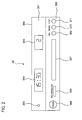
- FIG. 2 is a structural view showing an example of a front operation panel of the main operation section of the DVD recorder of the embodiment.
- a front operation panel 360 is comprised of a display section 361 and an operation section 362.
- a power supply state displaying light-emitting diode 363 for emitting, for example, red light when the power supply is off and emitting, for example, green light when the power supply is on; a first display section 364 for displaying the time etc.; and a second display section 365 for displaying a selected channel etc.
- a power supply key 366 for turning the power supply of the apparatus on and off; a tray 367 for withdrawing a DVD etc.
- each configuration element on the front operation panel 360 are provided merely as an example and are by no means limiting.
- FIG. 3 is a view showing a structure for data recorded on a DVD video optical disc of the embodiment.
- a VOBS Video Object Set
- VOB_IND1, VOB_IND2, ... , VOB_INDi Video Objects
- the IND1, IND2, ... , INDi indicate identification numbers.
- Each VOB is then constructed from a plurality of cells (Cell).
- VOB_IND1 is comprised of a plurality of cells, C_IDN1, C_IDN2, ... , C_IDNj.
- the IDN 1, IDN2, ... , IDNj indicate identification numbers.
- cell C_IDN1 is comprised of a plurality of VOBUs (Video Object Units). Each VOBU then contains NV_PCK (Navigation Pack), A_PCK (Audio Pack), V_PCK (Video Pack), and SP_PCK (Sub-Picture Pack).
- NV_PCK Network Control Key
- A_PCK Audio Pack
- V_PCK Video Pack
- SP_PCK Sub-Picture Pack
- the NV_PCK and the A_PCK are constructed from, for example, 2048 bytes respectively, of, for example, a fourteen byte pack header (Pack Header), a twenty-four byte system header (System header), a six byte packet header (Packet header), a one byte sub-stream identifier (Sub_stream_id), 979 bytes of presentation control information data (PCI data), six bytes of packet header (Packet header), one byte of sub-stream identifier (Sub_stream_id), and 1017 bytes of data search information data (DSI data).
- a fourteen byte pack header Pack Header
- System header system header
- Packet header a six byte packet header
- Sub_stream_id 979 bytes of presentation control information data
- PCI data presentation control information data
- DSI data data search information data
- a presentation control packet has a six-byte packet header (Packet header), a one-byte sub-stream identifier (Sub_steam_id), and 979 bytes of presentation control information data (PCI data).
- a data search information packet has a six-byte packet header (Packet header), a one-byte sub-stream identifier (Sub_steam_id), and 1017 bytes of data search information data (DSI data).
- FIG. 4 is a view illustrating content of a power failure recovery selection screen displayed on a display apparatus of the embodiment.
- a message "Interrupt the power failure recovery process and open the tray? Yes or No. Please note that recovery of data recorded to the disc cannot be guaranteed when the power failure recovery process is interrupted.” is then displayed on the power failure recovery selection screen.
- the power failure recovery process is then interrupted when the remote control unit 21 is operated and "Yes" is selected.
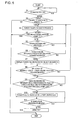
- FIG. 5 is a flowchart illustrating processing for up to execution of a power failure recovery interruption process from a power supply being turned on again after the optical disc recording and reproducing apparatus stops as a result of power failure occurring during a recording operation in this embodiment.
- a description is now given of the power failure recovery interruption process from the time the power supply of the apparatus being turned on again after the optical disc recording and reproducing apparatus stops as a result of power failure occurring during a recording operation in this embodiment with reference to this flowchart and FIG. 1 to FIG. 4.
- the power supply of the apparatus is turned on as a result of the user operating the power supply key (not shown) of the remote control unit 21 or the power supply key 363 of the main operation section 36 (step S1).
- the power failure recovery data present/absent determining section of the system controller 22 then accesses the flash ROM 23 and determines the presence or absence of power failure recovery data in the flash ROM 23 (step S2).
- step S2 when recording of information is being carried out to a recordable optical disc 1, data for address information and recording time information indicating how far recording has progressed for a region of the optical disc 1 every fixed time period is written to the flash ROM 23.
- step S3 When it is determined by the power failure recovery data present/absent determining section that there is no power failure recovery data in the flash ROM 23, the power supply did not go off as a result of power failure and it is therefore not necessary to carry out the power failure recovery process.
- the power failure recovery processing section of the system controller 22 carries out the predetermined power failure recovery process (step S3).
- the apparatus reads out recording information by every unit (VOBU described in FIG. 3 in the case of the DVD video specification) from the optical disc 1 based on the address information and the recording time information stored in the flash ROM 23 for temporary storage in the RAM 27. It is then confirmed whether the recording information (VOBU) by every unit is complete information (VOBU) in line with the disc specification.
- VOBU complete information
- step S4 While the power failure recovery process has not finished (step S4), when the tray opening and closing key 368 of the main operation section 36 is pressed by the user, the power failure recovery process interruption request determining section of the system controller 22 detects that the tray opening and closing key 368 has been pressed down (step S5). When it is determined that there is a power failure recovery process interruption request (step S6), the power failure recovery selection screen display processing section reads out the power failure recovery selection screen data from the flash ROM 23. Then the data is subjected to OSD processing by the OSD circuit 35 and converted by the video encoder 18 into an image signal which is then supplied to the display apparatus 20. The power failure recovery selection screen (refer to FIG. 4) is then displayed on the display apparatus 20 (step S7).
- the power failure recovery interruption processing section of the system controller 22 determines that interruption of the power failure recovery process is selected and decided at the power failure recovery selection screen (step S8). It is then determined whether or not reading of data (VOBU corresponding to the power failure recovery process) for the predetermined units relating to the power failure recovery process from the optical disc 1 is complete. When the reading is determined to be complete (step S9), a power failure recovery interruption process is carried out (step S10). When the power failure recovery interruption process is carried out, recovery of information (broadcast programs etc.) during the current recovery is given up, but a normal state is forcibly recovered instead.
- the power failure recovery interruption process completion determining section of the system controller 22 then detects that the power failure recovery interruption process is complete (step S11).
- the tray control section of the system controller 22 then drives a tray drive mechanism (not shown) and opens the tray 367 (step S12).
- the power failure recovery interruption process is complete.
- the optical disc recording and reproducing apparatus accepts the user operation as usual and allows execution of processing corresponding to the user operation.
Landscapes
- Engineering & Computer Science (AREA)
- Multimedia (AREA)
- Signal Processing (AREA)
- General Engineering & Computer Science (AREA)
- Software Systems (AREA)
- Computer Networks & Wireless Communication (AREA)
- Databases & Information Systems (AREA)
- Optical Recording Or Reproduction (AREA)
- Signal Processing For Digital Recording And Reproducing (AREA)
- Management Or Editing Of Information On Record Carriers (AREA)
Applications Claiming Priority (1)
| Application Number | Priority Date | Filing Date | Title |
|---|---|---|---|
| JP2006308884A JP4577299B2 (ja) | 2006-11-15 | 2006-11-15 | 光ディスク記録再生装置 |
Publications (3)
| Publication Number | Publication Date |
|---|---|
| EP1923883A2 true EP1923883A2 (de) | 2008-05-21 |
| EP1923883A3 EP1923883A3 (de) | 2013-12-11 |
| EP1923883B1 EP1923883B1 (de) | 2015-07-29 |
Family
ID=39092787
Family Applications (1)
| Application Number | Title | Priority Date | Filing Date |
|---|---|---|---|
| EP07021840.9A Ceased EP1923883B1 (de) | 2006-11-15 | 2007-11-09 | Aufnahme- und Wiedergabevorrichtung für eine optische Platte |
Country Status (3)
| Country | Link |
|---|---|
| US (1) | US7949897B2 (de) |
| EP (1) | EP1923883B1 (de) |
| JP (1) | JP4577299B2 (de) |
Families Citing this family (3)
| Publication number | Priority date | Publication date | Assignee | Title |
|---|---|---|---|---|
| TW201221987A (en) * | 2010-11-23 | 2012-06-01 | Inventec Corp | Detection method for configuration of power supply units and detection system using the same |
| US9093105B2 (en) * | 2011-12-09 | 2015-07-28 | Western Digital Technologies, Inc. | Disk drive charging capacitor using motor supply voltage during power failure |
| JP6042133B2 (ja) * | 2012-08-06 | 2016-12-14 | 京セラ株式会社 | 管理システム、管理方法、制御装置及び蓄電装置 |
Citations (1)
| Publication number | Priority date | Publication date | Assignee | Title |
|---|---|---|---|---|
| JP2006134142A (ja) | 2004-11-08 | 2006-05-25 | Canon Inc | 給電機能付きインターフェースをもつ電子装置 |
Family Cites Families (16)
| Publication number | Priority date | Publication date | Assignee | Title |
|---|---|---|---|---|
| JPH06274900A (ja) * | 1993-03-22 | 1994-09-30 | Alpine Electron Inc | ディスク演奏装置 |
| JP3448947B2 (ja) * | 1994-04-11 | 2003-09-22 | 株式会社日立製作所 | リモート印刷システムおよびそのリモート印刷方法 |
| JPH10289524A (ja) * | 1997-04-11 | 1998-10-27 | Sony Corp | 記録媒体駆動装置 |
| JP3618529B2 (ja) * | 1997-11-04 | 2005-02-09 | 富士通株式会社 | ディスクアレイ装置 |
| US7340153B2 (en) * | 2000-01-11 | 2008-03-04 | Hitachi, Ltd. | Apparatus and method for recording and reproducing information |
| JP3921031B2 (ja) * | 2000-05-12 | 2007-05-30 | 富士通株式会社 | 記憶装置 |
| CN1246764C (zh) | 2000-12-20 | 2006-03-22 | 皇家菲利浦电子有限公司 | 记录和重放装置电源故障的恢复机制 |
| US7116621B2 (en) * | 2001-01-25 | 2006-10-03 | Dphi Acquisitions, Inc. | System and method for handling commands in an optical disc drive |
| US7003620B2 (en) * | 2002-11-26 | 2006-02-21 | M-Systems Flash Disk Pioneers Ltd. | Appliance, including a flash memory, that is robust under power failure |
| JP2005276026A (ja) * | 2004-03-26 | 2005-10-06 | Hitachi Global Storage Technologies Netherlands Bv | データ記憶装置におけるエラー回復処理方法、データ記憶装置及び磁気ディスク記憶装置 |
| EP1738361A1 (de) * | 2004-04-14 | 2007-01-03 | Koninklijke Philips Electronics N.V. | Herunterfahrvorrichtung für ein optisches datenlaufwerk |
| JP2006004568A (ja) * | 2004-06-21 | 2006-01-05 | Canon Inc | 光学的情報記録再生装置 |
| US7134039B2 (en) * | 2004-07-06 | 2006-11-07 | Magnum Semiconductor, Inc. | Recovery of real-time video data after power loss |
| KR100612221B1 (ko) * | 2004-07-07 | 2006-08-16 | 삼성전자주식회사 | 데이터 복원 기능을 갖는 영상기록재생장치 및 그 방법 |
| US20070065105A1 (en) * | 2005-09-20 | 2007-03-22 | Mediatek Inc. | Data recovery method and system for a data recording |
| JP2007280501A (ja) * | 2006-04-06 | 2007-10-25 | Funai Electric Co Ltd | 光ディスク記録再生装置 |
-
2006
- 2006-11-15 JP JP2006308884A patent/JP4577299B2/ja not_active Expired - Fee Related
-
2007
- 2007-10-26 US US11/976,705 patent/US7949897B2/en not_active Expired - Fee Related
- 2007-11-09 EP EP07021840.9A patent/EP1923883B1/de not_active Ceased
Patent Citations (1)
| Publication number | Priority date | Publication date | Assignee | Title |
|---|---|---|---|---|
| JP2006134142A (ja) | 2004-11-08 | 2006-05-25 | Canon Inc | 給電機能付きインターフェースをもつ電子装置 |
Also Published As
| Publication number | Publication date |
|---|---|
| JP2008123637A (ja) | 2008-05-29 |
| US7949897B2 (en) | 2011-05-24 |
| JP4577299B2 (ja) | 2010-11-10 |
| EP1923883B1 (de) | 2015-07-29 |
| US20080114917A1 (en) | 2008-05-15 |
| EP1923883A3 (de) | 2013-12-11 |
Similar Documents
| Publication | Publication Date | Title |
|---|---|---|
| US6985420B2 (en) | Optically recorded data discrimination apparatus and associated methodology | |
| EP1923883B1 (de) | Aufnahme- und Wiedergabevorrichtung für eine optische Platte | |
| JP2004171704A (ja) | 光ディスク再生装置 | |
| EP1241666A2 (de) | Informationsaufzeichnung/wiedergabegerät | |
| US7734964B2 (en) | Optical disc recording/reproducing apparatus | |
| JP3855273B2 (ja) | 光ディスク再生装置 | |
| US20070036049A1 (en) | Dual-deck optical disc system and method of controlling the same | |
| EP1703508A2 (de) | Aufnahme-/Wiedergabevorrichtung für eine optische Platte | |
| JP2004071080A (ja) | 情報再生出力装置、方法、プログラム及び記録媒体 | |
| JP4187001B2 (ja) | 光ディスク記録再生装置 | |
| US7796859B2 (en) | DVD reproducing apparatus | |
| JP2003077222A (ja) | ディスク再生装置 | |
| JP2007323739A (ja) | 光ディスク装置 | |
| JP4434085B2 (ja) | 光ディスク装置 | |
| JP4433005B2 (ja) | 光ディスク記録再生装置 | |
| JP3938168B2 (ja) | データ記録再生装置 | |
| EP1638105A1 (de) | Wiedergabevorrichtung für optische Platten | |
| KR100551385B1 (ko) | Dvdr/vcr 복합기기에서의 타이머 녹화 방법 | |
| JP4325633B2 (ja) | 光ディスク装置 | |
| KR101137838B1 (ko) | 캡션 신호 기록 및 재생 관리방법 | |
| JP2006323895A (ja) | メディアの種別に応じた再生方法と再生装置 | |
| JP4232827B2 (ja) | 光ディスク装置 | |
| JP2007158531A (ja) | 光ディスク装置 | |
| JP2006294165A (ja) | データ記録再生装置 | |
| US20100189415A1 (en) | Recording medium reproducing device and reproducing method |
Legal Events
| Date | Code | Title | Description |
|---|---|---|---|
| PUAI | Public reference made under article 153(3) epc to a published international application that has entered the european phase |
Free format text: ORIGINAL CODE: 0009012 |
|
| AK | Designated contracting states |
Kind code of ref document: A2 Designated state(s): AT BE BG CH CY CZ DE DK EE ES FI FR GB GR HU IE IS IT LI LT LU LV MC MT NL PL PT RO SE SI SK TR |
|
| AX | Request for extension of the european patent |
Extension state: AL BA HR MK RS |
|
| REG | Reference to a national code |
Ref country code: DE Ref legal event code: R079 Ref document number: 602007042314 Country of ref document: DE Free format text: PREVIOUS MAIN CLASS: G11B0019020000 Ipc: G11B0027360000 |
|
| PUAL | Search report despatched |
Free format text: ORIGINAL CODE: 0009013 |
|
| AK | Designated contracting states |
Kind code of ref document: A3 Designated state(s): AT BE BG CH CY CZ DE DK EE ES FI FR GB GR HU IE IS IT LI LT LU LV MC MT NL PL PT RO SE SI SK TR |
|
| AX | Request for extension of the european patent |
Extension state: AL BA HR MK RS |
|
| RIC1 | Information provided on ipc code assigned before grant |
Ipc: G11B 19/04 20060101ALI20131105BHEP Ipc: H04N 5/783 20060101ALI20131105BHEP Ipc: H04N 5/85 20060101ALI20131105BHEP Ipc: G11B 27/36 20060101AFI20131105BHEP |
|
| 17P | Request for examination filed |
Effective date: 20140611 |
|
| RBV | Designated contracting states (corrected) |
Designated state(s): AT BE BG CH CY CZ DE DK EE ES FI FR GB GR HU IE IS IT LI LT LU LV MC MT NL PL PT RO SE SI SK TR |
|
| AKX | Designation fees paid |
Designated state(s): DE GB |
|
| GRAP | Despatch of communication of intention to grant a patent |
Free format text: ORIGINAL CODE: EPIDOSNIGR1 |
|
| INTG | Intention to grant announced |
Effective date: 20150317 |
|
| GRAS | Grant fee paid |
Free format text: ORIGINAL CODE: EPIDOSNIGR3 |
|
| GRAA | (expected) grant |
Free format text: ORIGINAL CODE: 0009210 |
|
| AK | Designated contracting states |
Kind code of ref document: B1 Designated state(s): DE GB |
|
| REG | Reference to a national code |
Ref country code: GB Ref legal event code: FG4D |
|
| REG | Reference to a national code |
Ref country code: DE Ref legal event code: R096 Ref document number: 602007042314 Country of ref document: DE |
|
| REG | Reference to a national code |
Ref country code: DE Ref legal event code: R097 Ref document number: 602007042314 Country of ref document: DE |
|
| PLBE | No opposition filed within time limit |
Free format text: ORIGINAL CODE: 0009261 |
|
| STAA | Information on the status of an ep patent application or granted ep patent |
Free format text: STATUS: NO OPPOSITION FILED WITHIN TIME LIMIT |
|
| 26N | No opposition filed |
Effective date: 20160502 |
|
| GBPC | Gb: european patent ceased through non-payment of renewal fee |
Effective date: 20151109 |
|
| PG25 | Lapsed in a contracting state [announced via postgrant information from national office to epo] |
Ref country code: GB Free format text: LAPSE BECAUSE OF NON-PAYMENT OF DUE FEES Effective date: 20151109 |
|
| PGFP | Annual fee paid to national office [announced via postgrant information from national office to epo] |
Ref country code: DE Payment date: 20161101 Year of fee payment: 10 |
|
| REG | Reference to a national code |
Ref country code: DE Ref legal event code: R084 Ref document number: 602007042314 Country of ref document: DE |
|
| REG | Reference to a national code |
Ref country code: DE Ref legal event code: R119 Ref document number: 602007042314 Country of ref document: DE |
|
| PG25 | Lapsed in a contracting state [announced via postgrant information from national office to epo] |
Ref country code: DE Free format text: LAPSE BECAUSE OF NON-PAYMENT OF DUE FEES Effective date: 20180602 |