EP1922781B1 - Pile secondaire au lithium a potentiel de taux de charge/decharge eleve et a faible croissance d'impedance - Google Patents
Pile secondaire au lithium a potentiel de taux de charge/decharge eleve et a faible croissance d'impedance Download PDFInfo
- Publication number
- EP1922781B1 EP1922781B1 EP06814452.6A EP06814452A EP1922781B1 EP 1922781 B1 EP1922781 B1 EP 1922781B1 EP 06814452 A EP06814452 A EP 06814452A EP 1922781 B1 EP1922781 B1 EP 1922781B1
- Authority
- EP
- European Patent Office
- Prior art keywords
- cell
- lithium
- charge
- carbonate
- impedance
- Prior art date
- Legal status (The legal status is an assumption and is not a legal conclusion. Google has not performed a legal analysis and makes no representation as to the accuracy of the status listed.)
- Active
Links
- 229910052744 lithium Inorganic materials 0.000 title claims description 129
- WHXSMMKQMYFTQS-UHFFFAOYSA-N Lithium Chemical compound [Li] WHXSMMKQMYFTQS-UHFFFAOYSA-N 0.000 title claims description 119
- 239000003792 electrolyte Substances 0.000 claims description 52
- OKTJSMMVPCPJKN-UHFFFAOYSA-N Carbon Chemical compound [C] OKTJSMMVPCPJKN-UHFFFAOYSA-N 0.000 claims description 49
- 238000000034 method Methods 0.000 claims description 49
- 150000001875 compounds Chemical class 0.000 claims description 47
- 229910000319 transition metal phosphate Inorganic materials 0.000 claims description 43
- 229910052799 carbon Inorganic materials 0.000 claims description 33
- XEEYBQQBJWHFJM-UHFFFAOYSA-N Iron Chemical compound [Fe] XEEYBQQBJWHFJM-UHFFFAOYSA-N 0.000 claims description 31
- RUOJZAUFBMNUDX-UHFFFAOYSA-N propylene carbonate Chemical compound CC1COC(=O)O1 RUOJZAUFBMNUDX-UHFFFAOYSA-N 0.000 claims description 31
- 229910052751 metal Inorganic materials 0.000 claims description 29
- 239000002184 metal Substances 0.000 claims description 29
- KMTRUDSVKNLOMY-UHFFFAOYSA-N Ethylene carbonate Chemical compound O=C1OCCO1 KMTRUDSVKNLOMY-UHFFFAOYSA-N 0.000 claims description 28
- 230000001351 cycling effect Effects 0.000 claims description 27
- 230000007423 decrease Effects 0.000 claims description 27
- 229910019142 PO4 Inorganic materials 0.000 claims description 26
- 239000002245 particle Substances 0.000 claims description 26
- 229910001290 LiPF6 Inorganic materials 0.000 claims description 21
- JBTWLSYIZRCDFO-UHFFFAOYSA-N ethyl methyl carbonate Chemical compound CCOC(=O)OC JBTWLSYIZRCDFO-UHFFFAOYSA-N 0.000 claims description 20
- 238000003860 storage Methods 0.000 claims description 20
- 238000007600 charging Methods 0.000 claims description 18
- 239000003960 organic solvent Substances 0.000 claims description 18
- IEJIGPNLZYLLBP-UHFFFAOYSA-N dimethyl carbonate Chemical compound COC(=O)OC IEJIGPNLZYLLBP-UHFFFAOYSA-N 0.000 claims description 16
- 229910002804 graphite Inorganic materials 0.000 claims description 16
- 239000010439 graphite Substances 0.000 claims description 16
- 239000002931 mesocarbon microbead Substances 0.000 claims description 16
- VAYTZRYEBVHVLE-UHFFFAOYSA-N 1,3-dioxol-2-one Chemical compound O=C1OC=CO1 VAYTZRYEBVHVLE-UHFFFAOYSA-N 0.000 claims description 15
- PXHVJJICTQNCMI-UHFFFAOYSA-N Nickel Chemical compound [Ni] PXHVJJICTQNCMI-UHFFFAOYSA-N 0.000 claims description 14
- 229910052723 transition metal Inorganic materials 0.000 claims description 14
- 150000003624 transition metals Chemical class 0.000 claims description 14
- 229910052742 iron Inorganic materials 0.000 claims description 13
- 238000004891 communication Methods 0.000 claims description 12
- OIFBSDVPJOWBCH-UHFFFAOYSA-N Diethyl carbonate Chemical compound CCOC(=O)OCC OIFBSDVPJOWBCH-UHFFFAOYSA-N 0.000 claims description 10
- 229910052804 chromium Inorganic materials 0.000 claims description 10
- 239000011651 chromium Substances 0.000 claims description 10
- 150000002739 metals Chemical class 0.000 claims description 10
- 239000010936 titanium Substances 0.000 claims description 10
- 229910052720 vanadium Inorganic materials 0.000 claims description 10
- 229910052782 aluminium Inorganic materials 0.000 claims description 9
- 238000009830 intercalation Methods 0.000 claims description 9
- 229910052759 nickel Inorganic materials 0.000 claims description 9
- 239000010955 niobium Substances 0.000 claims description 9
- 229910052719 titanium Inorganic materials 0.000 claims description 9
- 229910052758 niobium Inorganic materials 0.000 claims description 8
- 229910052721 tungsten Inorganic materials 0.000 claims description 8
- 229910052726 zirconium Inorganic materials 0.000 claims description 8
- XAGFODPZIPBFFR-UHFFFAOYSA-N aluminium Chemical compound [Al] XAGFODPZIPBFFR-UHFFFAOYSA-N 0.000 claims description 7
- 230000002687 intercalation Effects 0.000 claims description 7
- 229910052749 magnesium Inorganic materials 0.000 claims description 7
- 239000011777 magnesium Substances 0.000 claims description 7
- 229910052715 tantalum Inorganic materials 0.000 claims description 7
- WFKWXMTUELFFGS-UHFFFAOYSA-N tungsten Chemical compound [W] WFKWXMTUELFFGS-UHFFFAOYSA-N 0.000 claims description 6
- 239000010937 tungsten Substances 0.000 claims description 6
- 229910015818 MPO4 Inorganic materials 0.000 claims description 5
- FYYHWMGAXLPEAU-UHFFFAOYSA-N Magnesium Chemical compound [Mg] FYYHWMGAXLPEAU-UHFFFAOYSA-N 0.000 claims description 5
- 229920000049 Carbon (fiber) Polymers 0.000 claims description 4
- VYZAMTAEIAYCRO-UHFFFAOYSA-N Chromium Chemical compound [Cr] VYZAMTAEIAYCRO-UHFFFAOYSA-N 0.000 claims description 4
- RTAQQCXQSZGOHL-UHFFFAOYSA-N Titanium Chemical compound [Ti] RTAQQCXQSZGOHL-UHFFFAOYSA-N 0.000 claims description 4
- QCWXUUIWCKQGHC-UHFFFAOYSA-N Zirconium Chemical compound [Zr] QCWXUUIWCKQGHC-UHFFFAOYSA-N 0.000 claims description 4
- 239000004917 carbon fiber Substances 0.000 claims description 4
- 229910017052 cobalt Inorganic materials 0.000 claims description 4
- 239000010941 cobalt Substances 0.000 claims description 4
- GUTLYIVDDKVIGB-UHFFFAOYSA-N cobalt atom Chemical compound [Co] GUTLYIVDDKVIGB-UHFFFAOYSA-N 0.000 claims description 4
- WPBNNNQJVZRUHP-UHFFFAOYSA-L manganese(2+);methyl n-[[2-(methoxycarbonylcarbamothioylamino)phenyl]carbamothioyl]carbamate;n-[2-(sulfidocarbothioylamino)ethyl]carbamodithioate Chemical compound [Mn+2].[S-]C(=S)NCCNC([S-])=S.COC(=O)NC(=S)NC1=CC=CC=C1NC(=S)NC(=O)OC WPBNNNQJVZRUHP-UHFFFAOYSA-L 0.000 claims description 4
- GUCVJGMIXFAOAE-UHFFFAOYSA-N niobium atom Chemical compound [Nb] GUCVJGMIXFAOAE-UHFFFAOYSA-N 0.000 claims description 4
- GUVRBAGPIYLISA-UHFFFAOYSA-N tantalum atom Chemical compound [Ta] GUVRBAGPIYLISA-UHFFFAOYSA-N 0.000 claims description 4
- GPPXJZIENCGNKB-UHFFFAOYSA-N vanadium Chemical compound [V]#[V] GPPXJZIENCGNKB-UHFFFAOYSA-N 0.000 claims description 4
- 229910009406 Li1-xMPO4 Inorganic materials 0.000 claims description 2
- 239000004411 aluminium Substances 0.000 claims 1
- 210000004027 cell Anatomy 0.000 description 273
- 229910001416 lithium ion Inorganic materials 0.000 description 85
- 239000000203 mixture Substances 0.000 description 85
- 239000000463 material Substances 0.000 description 45
- 239000010410 layer Substances 0.000 description 27
- 206010011906 Death Diseases 0.000 description 26
- HBBGRARXTFLTSG-UHFFFAOYSA-N Lithium ion Chemical compound [Li+] HBBGRARXTFLTSG-UHFFFAOYSA-N 0.000 description 26
- -1 electrode porosity Substances 0.000 description 26
- 238000012360 testing method Methods 0.000 description 25
- 239000010450 olivine Substances 0.000 description 20
- 229910052609 olivine Inorganic materials 0.000 description 20
- 239000007774 positive electrode material Substances 0.000 description 20
- 239000012071 phase Substances 0.000 description 18
- 238000007747 plating Methods 0.000 description 17
- 230000001747 exhibiting effect Effects 0.000 description 16
- 239000011149 active material Substances 0.000 description 15
- 239000003513 alkali Substances 0.000 description 15
- 230000000052 comparative effect Effects 0.000 description 15
- 150000002500 ions Chemical class 0.000 description 15
- 239000011888 foil Substances 0.000 description 14
- 239000011263 electroactive material Substances 0.000 description 13
- 230000001172 regenerating effect Effects 0.000 description 13
- 239000006104 solid solution Substances 0.000 description 13
- 229910052493 LiFePO4 Inorganic materials 0.000 description 12
- 238000009792 diffusion process Methods 0.000 description 12
- 239000002904 solvent Substances 0.000 description 12
- 239000002019 doping agent Substances 0.000 description 11
- 150000003839 salts Chemical class 0.000 description 11
- 239000013078 crystal Substances 0.000 description 10
- 239000011232 storage material Substances 0.000 description 10
- XEKOWRVHYACXOJ-UHFFFAOYSA-N Ethyl acetate Chemical compound CCOC(C)=O XEKOWRVHYACXOJ-UHFFFAOYSA-N 0.000 description 9
- 238000005266 casting Methods 0.000 description 9
- 230000008859 change Effects 0.000 description 9
- 239000007772 electrode material Substances 0.000 description 9
- 230000007774 longterm Effects 0.000 description 9
- 239000011255 nonaqueous electrolyte Substances 0.000 description 9
- CSCPPACGZOOCGX-UHFFFAOYSA-N Acetone Chemical compound CC(C)=O CSCPPACGZOOCGX-UHFFFAOYSA-N 0.000 description 8
- IJGRMHOSHXDMSA-UHFFFAOYSA-N Atomic nitrogen Chemical compound N#N IJGRMHOSHXDMSA-UHFFFAOYSA-N 0.000 description 8
- 229910032387 LiCoO2 Inorganic materials 0.000 description 8
- 229910001305 LiMPO4 Inorganic materials 0.000 description 8
- 239000011230 binding agent Substances 0.000 description 8
- 238000012512 characterization method Methods 0.000 description 8
- 229910003002 lithium salt Inorganic materials 0.000 description 8
- 159000000002 lithium salts Chemical class 0.000 description 8
- 230000003647 oxidation Effects 0.000 description 8
- 238000007254 oxidation reaction Methods 0.000 description 8
- 229920000642 polymer Polymers 0.000 description 8
- 229920002981 polyvinylidene fluoride Polymers 0.000 description 8
- 150000001768 cations Chemical class 0.000 description 7
- 239000002482 conductive additive Substances 0.000 description 7
- 230000006870 function Effects 0.000 description 7
- 229910052748 manganese Inorganic materials 0.000 description 7
- 239000011572 manganese Substances 0.000 description 7
- 239000011148 porous material Substances 0.000 description 7
- 238000003490 calendering Methods 0.000 description 6
- 239000003575 carbonaceous material Substances 0.000 description 6
- 239000010406 cathode material Substances 0.000 description 6
- 230000003247 decreasing effect Effects 0.000 description 6
- 239000011244 liquid electrolyte Substances 0.000 description 6
- 238000002360 preparation method Methods 0.000 description 6
- 239000007784 solid electrolyte Substances 0.000 description 6
- 229920003048 styrene butadiene rubber Polymers 0.000 description 6
- 229910002097 Lithium manganese(III,IV) oxide Inorganic materials 0.000 description 5
- 230000015572 biosynthetic process Effects 0.000 description 5
- 238000006243 chemical reaction Methods 0.000 description 5
- 230000007547 defect Effects 0.000 description 5
- 238000013461 design Methods 0.000 description 5
- 230000000694 effects Effects 0.000 description 5
- 238000005259 measurement Methods 0.000 description 5
- 239000007773 negative electrode material Substances 0.000 description 5
- 239000000843 powder Substances 0.000 description 5
- 230000008569 process Effects 0.000 description 5
- 230000009467 reduction Effects 0.000 description 5
- 230000004044 response Effects 0.000 description 5
- 239000000243 solution Substances 0.000 description 5
- BQCIDUSAKPWEOX-UHFFFAOYSA-N 1,1-Difluoroethene Chemical compound FC(F)=C BQCIDUSAKPWEOX-UHFFFAOYSA-N 0.000 description 4
- 229920002943 EPDM rubber Polymers 0.000 description 4
- 229910003005 LiNiO2 Inorganic materials 0.000 description 4
- OAICVXFJPJFONN-UHFFFAOYSA-N Phosphorus Chemical compound [P] OAICVXFJPJFONN-UHFFFAOYSA-N 0.000 description 4
- 239000010405 anode material Substances 0.000 description 4
- QVGXLLKOCUKJST-UHFFFAOYSA-N atomic oxygen Chemical compound [O] QVGXLLKOCUKJST-UHFFFAOYSA-N 0.000 description 4
- 239000002134 carbon nanofiber Substances 0.000 description 4
- 230000015556 catabolic process Effects 0.000 description 4
- 230000007812 deficiency Effects 0.000 description 4
- 238000006731 degradation reaction Methods 0.000 description 4
- 239000003085 diluting agent Substances 0.000 description 4
- 239000002003 electrode paste Substances 0.000 description 4
- 229920000840 ethylene tetrafluoroethylene copolymer Polymers 0.000 description 4
- 229910052736 halogen Inorganic materials 0.000 description 4
- 150000002367 halogens Chemical class 0.000 description 4
- 238000010438 heat treatment Methods 0.000 description 4
- 229910000399 iron(III) phosphate Inorganic materials 0.000 description 4
- 238000012417 linear regression Methods 0.000 description 4
- GELKBWJHTRAYNV-UHFFFAOYSA-K lithium iron phosphate Chemical compound [Li+].[Fe+2].[O-]P([O-])([O-])=O GELKBWJHTRAYNV-UHFFFAOYSA-K 0.000 description 4
- ACFSQHQYDZIPRL-UHFFFAOYSA-N lithium;bis(1,1,2,2,2-pentafluoroethylsulfonyl)azanide Chemical compound [Li+].FC(F)(F)C(F)(F)S(=O)(=O)[N-]S(=O)(=O)C(F)(F)C(F)(F)F ACFSQHQYDZIPRL-UHFFFAOYSA-N 0.000 description 4
- TZIHFWKZFHZASV-UHFFFAOYSA-N methyl formate Chemical compound COC=O TZIHFWKZFHZASV-UHFFFAOYSA-N 0.000 description 4
- 229910052757 nitrogen Inorganic materials 0.000 description 4
- 229910052760 oxygen Inorganic materials 0.000 description 4
- 239000001301 oxygen Substances 0.000 description 4
- 229910052698 phosphorus Inorganic materials 0.000 description 4
- 239000011574 phosphorus Substances 0.000 description 4
- 229920001343 polytetrafluoroethylene Polymers 0.000 description 4
- 239000004810 polytetrafluoroethylene Substances 0.000 description 4
- 239000007858 starting material Substances 0.000 description 4
- YEJRWHAVMIAJKC-UHFFFAOYSA-N 4-Butyrolactone Chemical compound O=C1CCCO1 YEJRWHAVMIAJKC-UHFFFAOYSA-N 0.000 description 3
- WEVYAHXRMPXWCK-UHFFFAOYSA-N Acetonitrile Chemical compound CC#N WEVYAHXRMPXWCK-UHFFFAOYSA-N 0.000 description 3
- RYGMFSIKBFXOCR-UHFFFAOYSA-N Copper Chemical compound [Cu] RYGMFSIKBFXOCR-UHFFFAOYSA-N 0.000 description 3
- RTZKZFJDLAIYFH-UHFFFAOYSA-N Diethyl ether Chemical compound CCOCC RTZKZFJDLAIYFH-UHFFFAOYSA-N 0.000 description 3
- JGFBQFKZKSSODQ-UHFFFAOYSA-N Isothiocyanatocyclopropane Chemical compound S=C=NC1CC1 JGFBQFKZKSSODQ-UHFFFAOYSA-N 0.000 description 3
- 229910010681 LiFeO4 Inorganic materials 0.000 description 3
- 239000002228 NASICON Substances 0.000 description 3
- MUBZPKHOEPUJKR-UHFFFAOYSA-N Oxalic acid Chemical compound OC(=O)C(O)=O MUBZPKHOEPUJKR-UHFFFAOYSA-N 0.000 description 3
- 229910000540 VOPO4 Inorganic materials 0.000 description 3
- 229910052783 alkali metal Inorganic materials 0.000 description 3
- 150000001340 alkali metals Chemical class 0.000 description 3
- 238000004458 analytical method Methods 0.000 description 3
- 150000001450 anions Chemical class 0.000 description 3
- 229910021383 artificial graphite Inorganic materials 0.000 description 3
- PWLNAUNEAKQYLH-UHFFFAOYSA-N butyric acid octyl ester Natural products CCCCCCCCOC(=O)CCC PWLNAUNEAKQYLH-UHFFFAOYSA-N 0.000 description 3
- 125000004122 cyclic group Chemical group 0.000 description 3
- 238000007599 discharging Methods 0.000 description 3
- 238000009826 distribution Methods 0.000 description 3
- 239000008151 electrolyte solution Substances 0.000 description 3
- 229940021013 electrolyte solution Drugs 0.000 description 3
- 238000004146 energy storage Methods 0.000 description 3
- 239000007788 liquid Substances 0.000 description 3
- 238000004519 manufacturing process Methods 0.000 description 3
- 238000013178 mathematical model Methods 0.000 description 3
- UUIQMZJEGPQKFD-UHFFFAOYSA-N n-butyric acid methyl ester Natural products CCCC(=O)OC UUIQMZJEGPQKFD-UHFFFAOYSA-N 0.000 description 3
- 229910021382 natural graphite Inorganic materials 0.000 description 3
- 230000000737 periodic effect Effects 0.000 description 3
- 230000010287 polarization Effects 0.000 description 3
- 229920005596 polymer binder Polymers 0.000 description 3
- 239000002491 polymer binding agent Substances 0.000 description 3
- 239000007787 solid Substances 0.000 description 3
- 239000000126 substance Substances 0.000 description 3
- ZZXUZKXVROWEIF-UHFFFAOYSA-N 1,2-butylene carbonate Chemical compound CCC1COC(=O)O1 ZZXUZKXVROWEIF-UHFFFAOYSA-N 0.000 description 2
- KXJGSNRAQWDDJT-UHFFFAOYSA-N 1-acetyl-5-bromo-2h-indol-3-one Chemical compound BrC1=CC=C2N(C(=O)C)CC(=O)C2=C1 KXJGSNRAQWDDJT-UHFFFAOYSA-N 0.000 description 2
- HNAGHMKIPMKKBB-UHFFFAOYSA-N 1-benzylpyrrolidine-3-carboxamide Chemical compound C1C(C(=O)N)CCN1CC1=CC=CC=C1 HNAGHMKIPMKKBB-UHFFFAOYSA-N 0.000 description 2
- 229920002134 Carboxymethyl cellulose Polymers 0.000 description 2
- 229910011833 LiFe(P2O7) Inorganic materials 0.000 description 2
- ZOKXTWBITQBERF-UHFFFAOYSA-N Molybdenum Chemical compound [Mo] ZOKXTWBITQBERF-UHFFFAOYSA-N 0.000 description 2
- 239000002033 PVDF binder Substances 0.000 description 2
- 239000005062 Polybutadiene Substances 0.000 description 2
- 239000004642 Polyimide Substances 0.000 description 2
- XBDQKXXYIPTUBI-UHFFFAOYSA-M Propionate Chemical compound CCC([O-])=O XBDQKXXYIPTUBI-UHFFFAOYSA-M 0.000 description 2
- 239000002174 Styrene-butadiene Substances 0.000 description 2
- NINIDFKCEFEMDL-UHFFFAOYSA-N Sulfur Chemical compound [S] NINIDFKCEFEMDL-UHFFFAOYSA-N 0.000 description 2
- WYURNTSHIVDZCO-UHFFFAOYSA-N Tetrahydrofuran Chemical compound C1CCOC1 WYURNTSHIVDZCO-UHFFFAOYSA-N 0.000 description 2
- KXKVLQRXCPHEJC-UHFFFAOYSA-N acetic acid trimethyl ester Natural products COC(C)=O KXKVLQRXCPHEJC-UHFFFAOYSA-N 0.000 description 2
- 239000006230 acetylene black Substances 0.000 description 2
- 239000006183 anode active material Substances 0.000 description 2
- 229910052785 arsenic Inorganic materials 0.000 description 2
- RQNWIZPPADIBDY-UHFFFAOYSA-N arsenic atom Chemical compound [As] RQNWIZPPADIBDY-UHFFFAOYSA-N 0.000 description 2
- 230000009286 beneficial effect Effects 0.000 description 2
- 230000008901 benefit Effects 0.000 description 2
- OBNCKNCVKJNDBV-UHFFFAOYSA-N butanoic acid ethyl ester Natural products CCCC(=O)OCC OBNCKNCVKJNDBV-UHFFFAOYSA-N 0.000 description 2
- 239000002041 carbon nanotube Substances 0.000 description 2
- 229910021393 carbon nanotube Inorganic materials 0.000 description 2
- 150000004649 carbonic acid derivatives Chemical class 0.000 description 2
- 239000001768 carboxy methyl cellulose Substances 0.000 description 2
- 235000010948 carboxy methyl cellulose Nutrition 0.000 description 2
- 239000008112 carboxymethyl-cellulose Substances 0.000 description 2
- 239000006182 cathode active material Substances 0.000 description 2
- UUAGAQFQZIEFAH-UHFFFAOYSA-N chlorotrifluoroethylene Chemical group FC(F)=C(F)Cl UUAGAQFQZIEFAH-UHFFFAOYSA-N 0.000 description 2
- 238000010276 construction Methods 0.000 description 2
- 229920001577 copolymer Polymers 0.000 description 2
- 239000011889 copper foil Substances 0.000 description 2
- 210000001787 dendrite Anatomy 0.000 description 2
- 238000004512 die casting Methods 0.000 description 2
- 208000037265 diseases, disorders, signs and symptoms Diseases 0.000 description 2
- 208000035475 disorder Diseases 0.000 description 2
- 238000001035 drying Methods 0.000 description 2
- 230000005611 electricity Effects 0.000 description 2
- 238000005516 engineering process Methods 0.000 description 2
- 150000002148 esters Chemical class 0.000 description 2
- FKRCODPIKNYEAC-UHFFFAOYSA-N ethyl propionate Chemical compound CCOC(=O)CC FKRCODPIKNYEAC-UHFFFAOYSA-N 0.000 description 2
- VEPSWGHMGZQCIN-UHFFFAOYSA-H ferric oxalate Chemical compound [Fe+3].[Fe+3].[O-]C(=O)C([O-])=O.[O-]C(=O)C([O-])=O.[O-]C(=O)C([O-])=O VEPSWGHMGZQCIN-UHFFFAOYSA-H 0.000 description 2
- 239000000835 fiber Substances 0.000 description 2
- 239000010408 film Substances 0.000 description 2
- 239000007770 graphite material Substances 0.000 description 2
- 238000000227 grinding Methods 0.000 description 2
- 239000001257 hydrogen Substances 0.000 description 2
- 229910052739 hydrogen Inorganic materials 0.000 description 2
- 150000002431 hydrogen Chemical class 0.000 description 2
- 238000002847 impedance measurement Methods 0.000 description 2
- 230000006872 improvement Effects 0.000 description 2
- 238000003780 insertion Methods 0.000 description 2
- 230000037431 insertion Effects 0.000 description 2
- WBJZTOZJJYAKHQ-UHFFFAOYSA-K iron(3+) phosphate Chemical compound [Fe+3].[O-]P([O-])([O-])=O WBJZTOZJJYAKHQ-UHFFFAOYSA-K 0.000 description 2
- 239000005001 laminate film Substances 0.000 description 2
- XGZVUEUWXADBQD-UHFFFAOYSA-L lithium carbonate Chemical compound [Li+].[Li+].[O-]C([O-])=O XGZVUEUWXADBQD-UHFFFAOYSA-L 0.000 description 2
- 229910052808 lithium carbonate Inorganic materials 0.000 description 2
- 229910001496 lithium tetrafluoroborate Inorganic materials 0.000 description 2
- 238000011068 loading method Methods 0.000 description 2
- 230000014759 maintenance of location Effects 0.000 description 2
- 229910052752 metalloid Inorganic materials 0.000 description 2
- 150000002738 metalloids Chemical class 0.000 description 2
- VNWKTOKETHGBQD-UHFFFAOYSA-N methane Chemical compound C VNWKTOKETHGBQD-UHFFFAOYSA-N 0.000 description 2
- 239000011325 microbead Substances 0.000 description 2
- 238000003801 milling Methods 0.000 description 2
- 229910052750 molybdenum Inorganic materials 0.000 description 2
- 239000011733 molybdenum Substances 0.000 description 2
- YKYONYBAUNKHLG-UHFFFAOYSA-N n-Propyl acetate Natural products CCCOC(C)=O YKYONYBAUNKHLG-UHFFFAOYSA-N 0.000 description 2
- 230000037361 pathway Effects 0.000 description 2
- 150000003018 phosphorus compounds Chemical class 0.000 description 2
- 230000000704 physical effect Effects 0.000 description 2
- 229920003023 plastic Polymers 0.000 description 2
- 239000004033 plastic Substances 0.000 description 2
- 229920001200 poly(ethylene-vinyl acetate) Polymers 0.000 description 2
- 229920005569 poly(vinylidene fluoride-co-hexafluoropropylene) Polymers 0.000 description 2
- 229920002239 polyacrylonitrile Polymers 0.000 description 2
- 229920002857 polybutadiene Polymers 0.000 description 2
- 229920001721 polyimide Polymers 0.000 description 2
- 229920002620 polyvinyl fluoride Polymers 0.000 description 2
- 238000012545 processing Methods 0.000 description 2
- 239000000047 product Substances 0.000 description 2
- 229940090181 propyl acetate Drugs 0.000 description 2
- 230000002829 reductive effect Effects 0.000 description 2
- 230000002441 reversible effect Effects 0.000 description 2
- 238000012552 review Methods 0.000 description 2
- 239000002002 slurry Substances 0.000 description 2
- 239000008247 solid mixture Substances 0.000 description 2
- 238000003746 solid phase reaction Methods 0.000 description 2
- 238000010671 solid-state reaction Methods 0.000 description 2
- 238000001179 sorption measurement Methods 0.000 description 2
- 239000012798 spherical particle Substances 0.000 description 2
- 230000035882 stress Effects 0.000 description 2
- 238000006467 substitution reaction Methods 0.000 description 2
- 239000000758 substrate Substances 0.000 description 2
- 229910052717 sulfur Inorganic materials 0.000 description 2
- 239000011593 sulfur Substances 0.000 description 2
- 229920001897 terpolymer Polymers 0.000 description 2
- BFKJFAAPBSQJPD-UHFFFAOYSA-N tetrafluoroethene Chemical group FC(F)=C(F)F BFKJFAAPBSQJPD-UHFFFAOYSA-N 0.000 description 2
- 239000010409 thin film Substances 0.000 description 2
- NQPDZGIKBAWPEJ-UHFFFAOYSA-N valeric acid Chemical compound CCCCC(O)=O NQPDZGIKBAWPEJ-UHFFFAOYSA-N 0.000 description 2
- WDXYVJKNSMILOQ-UHFFFAOYSA-N 1,3,2-dioxathiolane 2-oxide Chemical compound O=S1OCCO1 WDXYVJKNSMILOQ-UHFFFAOYSA-N 0.000 description 1
- FSSPGSAQUIYDCN-UHFFFAOYSA-N 1,3-Propane sultone Chemical compound O=S1(=O)CCCO1 FSSPGSAQUIYDCN-UHFFFAOYSA-N 0.000 description 1
- WNXJIVFYUVYPPR-UHFFFAOYSA-N 1,3-dioxolane Chemical compound C1COCO1 WNXJIVFYUVYPPR-UHFFFAOYSA-N 0.000 description 1
- NLLOEPZYASPYON-UHFFFAOYSA-N 1,3-dioxolane-2-thione Chemical compound S=C1OCCO1 NLLOEPZYASPYON-UHFFFAOYSA-N 0.000 description 1
- JWUJQDFVADABEY-UHFFFAOYSA-N 2-methyltetrahydrofuran Chemical compound CC1CCCO1 JWUJQDFVADABEY-UHFFFAOYSA-N 0.000 description 1
- PPDFQRAASCRJAH-UHFFFAOYSA-N 2-methylthiolane 1,1-dioxide Chemical compound CC1CCCS1(=O)=O PPDFQRAASCRJAH-UHFFFAOYSA-N 0.000 description 1
- SBUOHGKIOVRDKY-UHFFFAOYSA-N 4-methyl-1,3-dioxolane Chemical compound CC1COCO1 SBUOHGKIOVRDKY-UHFFFAOYSA-N 0.000 description 1
- NIXOWILDQLNWCW-UHFFFAOYSA-M Acrylate Chemical compound [O-]C(=O)C=C NIXOWILDQLNWCW-UHFFFAOYSA-M 0.000 description 1
- 239000004254 Ammonium phosphate Substances 0.000 description 1
- 238000004438 BET method Methods 0.000 description 1
- CURLTUGMZLYLDI-UHFFFAOYSA-N Carbon dioxide Chemical compound O=C=O CURLTUGMZLYLDI-UHFFFAOYSA-N 0.000 description 1
- 229910014562 C—LiFePO4 Inorganic materials 0.000 description 1
- 208000033978 Device electrical impedance issue Diseases 0.000 description 1
- XTHFKEDIFFGKHM-UHFFFAOYSA-N Dimethoxyethane Chemical compound COCCOC XTHFKEDIFFGKHM-UHFFFAOYSA-N 0.000 description 1
- GZDFHIJNHHMENY-UHFFFAOYSA-N Dimethyl dicarbonate Chemical compound COC(=O)OC(=O)OC GZDFHIJNHHMENY-UHFFFAOYSA-N 0.000 description 1
- 229920006370 Kynar Polymers 0.000 description 1
- 229910009403 Li1-xM Inorganic materials 0.000 description 1
- 229910005046 Li1−x−zM1−zPO4 Inorganic materials 0.000 description 1
- 229910013458 LiC6 Inorganic materials 0.000 description 1
- 229910014071 LiMn1/3Co1/3Ni1/3O2 Inorganic materials 0.000 description 1
- 229910013396 LiN(SO2CF2CF3)2 LiAsF6 Inorganic materials 0.000 description 1
- 229910013406 LiN(SO2CF3)2 Inorganic materials 0.000 description 1
- 229910001319 LiVPO4F Inorganic materials 0.000 description 1
- 229910013335 LiyMPO4 Inorganic materials 0.000 description 1
- RJUFJBKOKNCXHH-UHFFFAOYSA-N Methyl propionate Chemical compound CCC(=O)OC RJUFJBKOKNCXHH-UHFFFAOYSA-N 0.000 description 1
- 241000282320 Panthera leo Species 0.000 description 1
- UJEWTUDSLQGTOA-UHFFFAOYSA-N Piretanide Chemical compound C=1C=CC=CC=1OC=1C(S(=O)(=O)N)=CC(C(O)=O)=CC=1N1CCCC1 UJEWTUDSLQGTOA-UHFFFAOYSA-N 0.000 description 1
- 229920003171 Poly (ethylene oxide) Polymers 0.000 description 1
- 241000156302 Porcine hemagglutinating encephalomyelitis virus Species 0.000 description 1
- 229910000831 Steel Inorganic materials 0.000 description 1
- 230000001133 acceleration Effects 0.000 description 1
- 125000002015 acyclic group Chemical group 0.000 description 1
- 239000000654 additive Substances 0.000 description 1
- 230000000996 additive effect Effects 0.000 description 1
- 239000002318 adhesion promoter Substances 0.000 description 1
- 239000002390 adhesive tape Substances 0.000 description 1
- 150000004703 alkoxides Chemical class 0.000 description 1
- 239000000956 alloy Substances 0.000 description 1
- 229910045601 alloy Inorganic materials 0.000 description 1
- LFVGISIMTYGQHF-UHFFFAOYSA-N ammonium dihydrogen phosphate Chemical compound [NH4+].OP(O)([O-])=O LFVGISIMTYGQHF-UHFFFAOYSA-N 0.000 description 1
- 229910000387 ammonium dihydrogen phosphate Inorganic materials 0.000 description 1
- 229910000148 ammonium phosphate Inorganic materials 0.000 description 1
- 235000019289 ammonium phosphates Nutrition 0.000 description 1
- 125000004429 atom Chemical group 0.000 description 1
- 238000004630 atomic force microscopy Methods 0.000 description 1
- 230000003190 augmentative effect Effects 0.000 description 1
- 230000005540 biological transmission Effects 0.000 description 1
- 238000009835 boiling Methods 0.000 description 1
- CTZGGNZWFSDEGK-UHFFFAOYSA-N butyl ethyl carbonate Chemical compound [CH2]COC(=O)OCCCC CTZGGNZWFSDEGK-UHFFFAOYSA-N 0.000 description 1
- FWBMVXOCTXTBAD-UHFFFAOYSA-N butyl methyl carbonate Chemical compound CCCCOC(=O)OC FWBMVXOCTXTBAD-UHFFFAOYSA-N 0.000 description 1
- VASVAWIFVXAQMI-UHFFFAOYSA-N butyl propyl carbonate Chemical compound CCCCOC(=O)OCCC VASVAWIFVXAQMI-UHFFFAOYSA-N 0.000 description 1
- 239000004203 carnauba wax Substances 0.000 description 1
- 210000003850 cellular structure Anatomy 0.000 description 1
- 238000000975 co-precipitation Methods 0.000 description 1
- 239000011248 coating agent Substances 0.000 description 1
- 238000000576 coating method Methods 0.000 description 1
- 238000002485 combustion reaction Methods 0.000 description 1
- 238000010277 constant-current charging Methods 0.000 description 1
- 229910052802 copper Inorganic materials 0.000 description 1
- 239000010949 copper Substances 0.000 description 1
- 229920006037 cross link polymer Polymers 0.000 description 1
- 238000002425 crystallisation Methods 0.000 description 1
- 230000008025 crystallization Effects 0.000 description 1
- 238000009831 deintercalation Methods 0.000 description 1
- 238000000280 densification Methods 0.000 description 1
- 238000001514 detection method Methods 0.000 description 1
- 230000006866 deterioration Effects 0.000 description 1
- MNNHAPBLZZVQHP-UHFFFAOYSA-N diammonium hydrogen phosphate Chemical compound [NH4+].[NH4+].OP([O-])([O-])=O MNNHAPBLZZVQHP-UHFFFAOYSA-N 0.000 description 1
- QLVWOKQMDLQXNN-UHFFFAOYSA-N dibutyl carbonate Chemical compound CCCCOC(=O)OCCCC QLVWOKQMDLQXNN-UHFFFAOYSA-N 0.000 description 1
- 235000010300 dimethyl dicarbonate Nutrition 0.000 description 1
- 239000004316 dimethyl dicarbonate Substances 0.000 description 1
- VUPKGFBOKBGHFZ-UHFFFAOYSA-N dipropyl carbonate Chemical compound CCCOC(=O)OCCC VUPKGFBOKBGHFZ-UHFFFAOYSA-N 0.000 description 1
- 238000006073 displacement reaction Methods 0.000 description 1
- 238000000157 electrochemical-induced impedance spectroscopy Methods 0.000 description 1
- 239000011267 electrode slurry Substances 0.000 description 1
- UARGAUQGVANXCB-UHFFFAOYSA-N ethanol;zirconium Chemical compound [Zr].CCO.CCO.CCO.CCO UARGAUQGVANXCB-UHFFFAOYSA-N 0.000 description 1
- CYEDOLFRAIXARV-UHFFFAOYSA-N ethyl propyl carbonate Chemical compound CCCOC(=O)OCC CYEDOLFRAIXARV-UHFFFAOYSA-N 0.000 description 1
- 230000005284 excitation Effects 0.000 description 1
- 238000002474 experimental method Methods 0.000 description 1
- 239000004744 fabric Substances 0.000 description 1
- 239000012467 final product Substances 0.000 description 1
- 238000010304 firing Methods 0.000 description 1
- 230000002431 foraging effect Effects 0.000 description 1
- 238000009472 formulation Methods 0.000 description 1
- 239000000446 fuel Substances 0.000 description 1
- 239000013538 functional additive Substances 0.000 description 1
- 239000007789 gas Substances 0.000 description 1
- 239000011245 gel electrolyte Substances 0.000 description 1
- 229910021389 graphene Inorganic materials 0.000 description 1
- BHEPBYXIRTUNPN-UHFFFAOYSA-N hydridophosphorus(.) (triplet) Chemical class [PH] BHEPBYXIRTUNPN-UHFFFAOYSA-N 0.000 description 1
- 230000001771 impaired effect Effects 0.000 description 1
- 230000008595 infiltration Effects 0.000 description 1
- 238000001764 infiltration Methods 0.000 description 1
- 229910003480 inorganic solid Inorganic materials 0.000 description 1
- 230000016507 interphase Effects 0.000 description 1
- 150000002506 iron compounds Chemical class 0.000 description 1
- 229910000398 iron phosphate Inorganic materials 0.000 description 1
- 150000002605 large molecules Chemical class 0.000 description 1
- 230000000670 limiting effect Effects 0.000 description 1
- 239000007791 liquid phase Substances 0.000 description 1
- 150000002641 lithium Chemical class 0.000 description 1
- 229910001540 lithium hexafluoroarsenate(V) Inorganic materials 0.000 description 1
- MHCFAGZWMAWTNR-UHFFFAOYSA-M lithium perchlorate Chemical compound [Li+].[O-]Cl(=O)(=O)=O MHCFAGZWMAWTNR-UHFFFAOYSA-M 0.000 description 1
- 229910001486 lithium perchlorate Inorganic materials 0.000 description 1
- 229910001386 lithium phosphate Inorganic materials 0.000 description 1
- QSZMZKBZAYQGRS-UHFFFAOYSA-N lithium;bis(trifluoromethylsulfonyl)azanide Chemical compound [Li+].FC(F)(F)S(=O)(=O)[N-]S(=O)(=O)C(F)(F)F QSZMZKBZAYQGRS-UHFFFAOYSA-N 0.000 description 1
- MCVFFRWZNYZUIJ-UHFFFAOYSA-M lithium;trifluoromethanesulfonate Chemical compound [Li+].[O-]S(=O)(=O)C(F)(F)F MCVFFRWZNYZUIJ-UHFFFAOYSA-M 0.000 description 1
- 230000007246 mechanism Effects 0.000 description 1
- 238000010303 mechanochemical reaction Methods 0.000 description 1
- 229910021645 metal ion Inorganic materials 0.000 description 1
- 229910044991 metal oxide Inorganic materials 0.000 description 1
- 150000004706 metal oxides Chemical class 0.000 description 1
- 229940017219 methyl propionate Drugs 0.000 description 1
- KKQAVHGECIBFRQ-UHFFFAOYSA-N methyl propyl carbonate Chemical compound CCCOC(=O)OC KKQAVHGECIBFRQ-UHFFFAOYSA-N 0.000 description 1
- 238000012544 monitoring process Methods 0.000 description 1
- 235000019837 monoammonium phosphate Nutrition 0.000 description 1
- 239000002114 nanocomposite Substances 0.000 description 1
- 239000002073 nanorod Substances 0.000 description 1
- 239000005486 organic electrolyte Substances 0.000 description 1
- 235000006408 oxalic acid Nutrition 0.000 description 1
- 230000001590 oxidative effect Effects 0.000 description 1
- 239000003973 paint Substances 0.000 description 1
- 239000000123 paper Substances 0.000 description 1
- 230000036961 partial effect Effects 0.000 description 1
- 150000003013 phosphoric acid derivatives Chemical class 0.000 description 1
- 229920000193 polymethacrylate Polymers 0.000 description 1
- 229920000098 polyolefin Polymers 0.000 description 1
- FVSKHRXBFJPNKK-UHFFFAOYSA-N propionitrile Chemical compound CCC#N FVSKHRXBFJPNKK-UHFFFAOYSA-N 0.000 description 1
- 239000011241 protective layer Substances 0.000 description 1
- 239000000376 reactant Substances 0.000 description 1
- 230000009257 reactivity Effects 0.000 description 1
- 230000008929 regeneration Effects 0.000 description 1
- 238000011069 regeneration method Methods 0.000 description 1
- 239000012266 salt solution Substances 0.000 description 1
- 238000000790 scattering method Methods 0.000 description 1
- 229910052604 silicate mineral Inorganic materials 0.000 description 1
- 238000005549 size reduction Methods 0.000 description 1
- 238000005118 spray pyrolysis Methods 0.000 description 1
- 239000010959 steel Substances 0.000 description 1
- 238000003756 stirring Methods 0.000 description 1
- HXJUTPCZVOIRIF-UHFFFAOYSA-N sulfolane Chemical compound O=S1(=O)CCCC1 HXJUTPCZVOIRIF-UHFFFAOYSA-N 0.000 description 1
- 238000006557 surface reaction Methods 0.000 description 1
- 230000002194 synthesizing effect Effects 0.000 description 1
- YLQBMQCUIZJEEH-UHFFFAOYSA-N tetrahydrofuran Natural products C=1C=COC=1 YLQBMQCUIZJEEH-UHFFFAOYSA-N 0.000 description 1
- 238000012546 transfer Methods 0.000 description 1
- 229910000314 transition metal oxide Inorganic materials 0.000 description 1
- TWQULNDIKKJZPH-UHFFFAOYSA-K trilithium;phosphate Chemical compound [Li+].[Li+].[Li+].[O-]P([O-])([O-])=O TWQULNDIKKJZPH-UHFFFAOYSA-K 0.000 description 1
- XLYOFNOQVPJJNP-UHFFFAOYSA-N water Substances O XLYOFNOQVPJJNP-UHFFFAOYSA-N 0.000 description 1
- 238000003466 welding Methods 0.000 description 1
Images


Classifications
-
- H—ELECTRICITY
- H01—ELECTRIC ELEMENTS
- H01M—PROCESSES OR MEANS, e.g. BATTERIES, FOR THE DIRECT CONVERSION OF CHEMICAL ENERGY INTO ELECTRICAL ENERGY
- H01M10/00—Secondary cells; Manufacture thereof
- H01M10/05—Accumulators with non-aqueous electrolyte
- H01M10/052—Li-accumulators
- H01M10/0525—Rocking-chair batteries, i.e. batteries with lithium insertion or intercalation in both electrodes; Lithium-ion batteries
-
- H—ELECTRICITY
- H01—ELECTRIC ELEMENTS
- H01M—PROCESSES OR MEANS, e.g. BATTERIES, FOR THE DIRECT CONVERSION OF CHEMICAL ENERGY INTO ELECTRICAL ENERGY
- H01M10/00—Secondary cells; Manufacture thereof
- H01M10/05—Accumulators with non-aqueous electrolyte
- H01M10/056—Accumulators with non-aqueous electrolyte characterised by the materials used as electrolytes, e.g. mixed inorganic/organic electrolytes
- H01M10/0564—Accumulators with non-aqueous electrolyte characterised by the materials used as electrolytes, e.g. mixed inorganic/organic electrolytes the electrolyte being constituted of organic materials only
- H01M10/0566—Liquid materials
- H01M10/0568—Liquid materials characterised by the solutes
-
- H—ELECTRICITY
- H01—ELECTRIC ELEMENTS
- H01M—PROCESSES OR MEANS, e.g. BATTERIES, FOR THE DIRECT CONVERSION OF CHEMICAL ENERGY INTO ELECTRICAL ENERGY
- H01M10/00—Secondary cells; Manufacture thereof
- H01M10/05—Accumulators with non-aqueous electrolyte
- H01M10/056—Accumulators with non-aqueous electrolyte characterised by the materials used as electrolytes, e.g. mixed inorganic/organic electrolytes
- H01M10/0564—Accumulators with non-aqueous electrolyte characterised by the materials used as electrolytes, e.g. mixed inorganic/organic electrolytes the electrolyte being constituted of organic materials only
- H01M10/0566—Liquid materials
- H01M10/0569—Liquid materials characterised by the solvents
-
- H—ELECTRICITY
- H01—ELECTRIC ELEMENTS
- H01M—PROCESSES OR MEANS, e.g. BATTERIES, FOR THE DIRECT CONVERSION OF CHEMICAL ENERGY INTO ELECTRICAL ENERGY
- H01M4/00—Electrodes
- H01M4/02—Electrodes composed of, or comprising, active material
- H01M4/13—Electrodes for accumulators with non-aqueous electrolyte, e.g. for lithium-accumulators; Processes of manufacture thereof
- H01M4/133—Electrodes based on carbonaceous material, e.g. graphite-intercalation compounds or CFx
-
- H—ELECTRICITY
- H01—ELECTRIC ELEMENTS
- H01M—PROCESSES OR MEANS, e.g. BATTERIES, FOR THE DIRECT CONVERSION OF CHEMICAL ENERGY INTO ELECTRICAL ENERGY
- H01M4/00—Electrodes
- H01M4/02—Electrodes composed of, or comprising, active material
- H01M4/13—Electrodes for accumulators with non-aqueous electrolyte, e.g. for lithium-accumulators; Processes of manufacture thereof
- H01M4/136—Electrodes based on inorganic compounds other than oxides or hydroxides, e.g. sulfides, selenides, tellurides, halogenides or LiCoFy
-
- H—ELECTRICITY
- H01—ELECTRIC ELEMENTS
- H01M—PROCESSES OR MEANS, e.g. BATTERIES, FOR THE DIRECT CONVERSION OF CHEMICAL ENERGY INTO ELECTRICAL ENERGY
- H01M4/00—Electrodes
- H01M4/02—Electrodes composed of, or comprising, active material
- H01M4/36—Selection of substances as active materials, active masses, active liquids
- H01M4/58—Selection of substances as active materials, active masses, active liquids of inorganic compounds other than oxides or hydroxides, e.g. sulfides, selenides, tellurides, halogenides or LiCoFy; of polyanionic structures, e.g. phosphates, silicates or borates
- H01M4/5825—Oxygenated metallic salts or polyanionic structures, e.g. borates, phosphates, silicates, olivines
-
- H—ELECTRICITY
- H01—ELECTRIC ELEMENTS
- H01M—PROCESSES OR MEANS, e.g. BATTERIES, FOR THE DIRECT CONVERSION OF CHEMICAL ENERGY INTO ELECTRICAL ENERGY
- H01M4/00—Electrodes
- H01M4/02—Electrodes composed of, or comprising, active material
- H01M4/36—Selection of substances as active materials, active masses, active liquids
- H01M4/58—Selection of substances as active materials, active masses, active liquids of inorganic compounds other than oxides or hydroxides, e.g. sulfides, selenides, tellurides, halogenides or LiCoFy; of polyanionic structures, e.g. phosphates, silicates or borates
- H01M4/583—Carbonaceous material, e.g. graphite-intercalation compounds or CFx
- H01M4/587—Carbonaceous material, e.g. graphite-intercalation compounds or CFx for inserting or intercalating light metals
-
- H—ELECTRICITY
- H01—ELECTRIC ELEMENTS
- H01M—PROCESSES OR MEANS, e.g. BATTERIES, FOR THE DIRECT CONVERSION OF CHEMICAL ENERGY INTO ELECTRICAL ENERGY
- H01M2220/00—Batteries for particular applications
- H01M2220/20—Batteries in motive systems, e.g. vehicle, ship, plane
-
- H—ELECTRICITY
- H01—ELECTRIC ELEMENTS
- H01M—PROCESSES OR MEANS, e.g. BATTERIES, FOR THE DIRECT CONVERSION OF CHEMICAL ENERGY INTO ELECTRICAL ENERGY
- H01M2300/00—Electrolytes
- H01M2300/0017—Non-aqueous electrolytes
- H01M2300/0025—Organic electrolyte
-
- H—ELECTRICITY
- H01—ELECTRIC ELEMENTS
- H01M—PROCESSES OR MEANS, e.g. BATTERIES, FOR THE DIRECT CONVERSION OF CHEMICAL ENERGY INTO ELECTRICAL ENERGY
- H01M2300/00—Electrolytes
- H01M2300/0017—Non-aqueous electrolytes
- H01M2300/0025—Organic electrolyte
- H01M2300/0028—Organic electrolyte characterised by the solvent
- H01M2300/0037—Mixture of solvents
- H01M2300/0042—Four or more solvents
-
- Y—GENERAL TAGGING OF NEW TECHNOLOGICAL DEVELOPMENTS; GENERAL TAGGING OF CROSS-SECTIONAL TECHNOLOGIES SPANNING OVER SEVERAL SECTIONS OF THE IPC; TECHNICAL SUBJECTS COVERED BY FORMER USPC CROSS-REFERENCE ART COLLECTIONS [XRACs] AND DIGESTS
- Y02—TECHNOLOGIES OR APPLICATIONS FOR MITIGATION OR ADAPTATION AGAINST CLIMATE CHANGE
- Y02E—REDUCTION OF GREENHOUSE GAS [GHG] EMISSIONS, RELATED TO ENERGY GENERATION, TRANSMISSION OR DISTRIBUTION
- Y02E60/00—Enabling technologies; Technologies with a potential or indirect contribution to GHG emissions mitigation
- Y02E60/10—Energy storage using batteries
-
- Y—GENERAL TAGGING OF NEW TECHNOLOGICAL DEVELOPMENTS; GENERAL TAGGING OF CROSS-SECTIONAL TECHNOLOGIES SPANNING OVER SEVERAL SECTIONS OF THE IPC; TECHNICAL SUBJECTS COVERED BY FORMER USPC CROSS-REFERENCE ART COLLECTIONS [XRACs] AND DIGESTS
- Y02—TECHNOLOGIES OR APPLICATIONS FOR MITIGATION OR ADAPTATION AGAINST CLIMATE CHANGE
- Y02P—CLIMATE CHANGE MITIGATION TECHNOLOGIES IN THE PRODUCTION OR PROCESSING OF GOODS
- Y02P70/00—Climate change mitigation technologies in the production process for final industrial or consumer products
- Y02P70/50—Manufacturing or production processes characterised by the final manufactured product
Definitions
- the field relates to non-aqueous electrolyte secondary cells, and in particular a battery having a fast charge and discharge rate capability and low rate of capacity fade during such high rate cycling.
- the battery can exhibit low impedance growth, allowing for its use in hybrid electric vehicle applications and other high demand applications.
- Lithium-ion battery or lithium ion cell refers to a rechargeable battery having an anode capable of storing a substantial amount of lithium at a lithium chemical potential above that of lithium metal.
- non-aqueous secondary (rechargeable) cells using metallic lithium or its alloys as the negative electrode were the first rechargeable cells capable of generating high voltages and having high energy density.
- their capacity decreased rapidly during cycling, and that their reliability and safety were impaired by the growth of the so-called mossy lithium and lithium dendrites to a degree that precluded these cells from the consumer market.
- the few lithium-metal rechargeable batteries which, from time to time, were being actively marketed, were recommended to be charged at a rate no higher than ca. C/10 (10-hour) rate to minimize the dendritic growth.
- the process of SEI formation and its partial renewal during battery cycling and storage irreversibly consumes a fraction of the active lithium from the battery and results in a loss of capacity. This loss is readily visible when one compares the amount of charge used during the first charge and then the discharge of the battery, a so-called formation cycle.
- the positive active material is oxidized and Li + ions diffuse in the liquid electrolyte towards the carbon negative electrode, where they are reduced to Li 0 and intercalated between the graphene layers of the carbon structure.
- a significant fraction of this first-reduced lithium up to ca. 50 %, but more typically between 5 and 15 % of the intercalatable lithium, reacts to form the above-mentioned SEI.
- the amount of Li available in the positive electrode material has to be less than the sum of lithium necessary for the formation of the SEI and the available lithium intercalation capacity of the carbon material. If the amount of lithium removed from the positive electrode material is greater than that sum, the excess lithium will be deposited, or plated, as metallic lithium on the external surfaces of the carbon particles.
- the plated lithium is in the form of a very reactive high-surface-area deposit, so-called 'mossy lithium', which will not only degrade the battery performance due to its high electrical impedance, but will also seriously compromise its safety.
- Li-ion batteries Due to the strong possibility of lithium plating on the carbon anode during the high-rate charge, manufacturers of Li-ion batteries recommend that such batteries are charged at an equivalent current no greater than one time the nominal cell capacity (1C) until the upper maximum charging voltage is reached, followed by a constant-current (taper) segment (http://www.panasonic.com/industrial/battery/oem/images/pdf/Panasonic_LiIon_Char ging.pdf). In practice, the charging step lasts from 1.5 to 2.5 hours, which is too long for certain applications, such as battery-powered tools, certain electronic devices and electric vehicles.
- Hybrid electric vehicles are a particularly demanding application for batteries.
- Hybrid electric vehicles are powered by an energy conversion unit (e.g., a combustion engine or fuel cell), and an energy storage device (e.g ., batteries).
- Hybrid electric vehicles can have a parallel design, in which the energy conversion unit and an electric propulsion system powered by the batteries are connected directly to the vehicle's wheels.
- the primary engine generally is used for highway driving, while the electric motor supplies power when the vehicle is moving at low speeds and during hill climbs, acceleration, and other high demand applications.
- Series designs are also employed, in which the primary engine is connected to a generator that produces electricity. The electricity charges the batteries, which drive an electric motor that powers the wheels.
- the U.S. government has defined performance criteria for batteries to be used in hybrid electric vehicles. See, e.g., U.S. Department of Energy, FreedomCAR Battery Test Manual for Power-Assist Hybrid Electric Vehicles (October, 2003 ).
- the battery should have a minimum pulse discharge power of 25 kW (for 10 seconds), a minimum peak regenerative pulse power of 20 kW (for 10 seconds), a total available energy of 300 Wh (at C 1 /1 rate), a cycle life of 300,000 cycles, and a calendar life of 15 years.
- Maximum weight, volume, and cost are also defined.
- Impedance growth detracts from the useful life of a battery.
- the impedance of a battery grows over time as the battery ages and repeated charge and discharge cycles lead to degradation of the electrode materials. Impedance growth is increased at higher temperatures. Due to the long battery life required for hybrid electric vehicle applications, impedance growth becomes an important factor toward the end of battery life. For cells exhibiting typical impedance growth (e.g ., 30-50% over 12 years), battery packs must be oversized, or provided initially with excess capacity, so that they can meet the performance requirements throughout the entire battery life.
- Oversizing helps reduce the stress on the battery in two ways: 1) it reduces the current or power each cell must deliver and 2) it allows for loss of power or performance, while still meeting the requirements at end-of-life.
- This oversizing disadvantageously adds to the weight, volume, and cost of the battery packs.
- US 2004/122178 relates to crosslinked polymers useful as electrolytes in rechargeable batteries.
- WO 98/12761 describes an electrochemical cell which comprises a first electrode and a second electrode.
- the first electrode comprises a phosphorous compound of the nominal general formula Li3E'aE"b(PO4)3.
- E' and E" are the same, they may be metals having more than one oxidation state. Where E' and E" are different from one another, they may be selected from the group of metals having more than one oxidation state.
- US 6,447,951 describes an electrochemical cell which comprises an electrode having a lithium metal phosphorous compound.
- Li-ion battery capable of high charge and discharge rates that is inexpensive to make, safe during extended high-electrical-stress use, having high energy and power capability, and exhibiting low loss of capacity and discharge power after numerous high-rate charge and discharge cycles.
- the battery is useful in high-rate applications, and can exhibit low impedance growth, allowing for its use in hybrid electric vehicle applications and other applications that rely on the availability of high power over long periods of time.
- the positive lithium storage electrode and the negative electrode of the cell are both capable of reversibly intercalating lithium at a high rate. The cell does not plate lithium during charging, resulting in negligible capacity fade over many charge cycles.
- the high-performance lithium-ion cell is capable of repeated, safe and stable charge and discharge at exceptionally high rates of charge and discharge.
- a battery can be charged at 10C rate and discharged at 20C rate, with a capacity loss as little as 0.008 % per cycle over more than 1,000 cycles.
- the secondary cell can achieve up to 95% state of charge in as little as six minutes.
- One aspect provides a lithium secondary cell containing a positive electrode that includes a lithium transition metal phosphate compound, a negative electrode that includes carbon, and an electrolyte in contact with and separating the positive electrode and negative electrode.
- the cell exhibits impedance growth of no more than about 10% for every 1000 charge-discharge cycles at a temperature of up to 60°C. In some embodiments, the charge-discharge cycles are deep discharge cycles.
- the cell further includes a positive electrode current collector in electronic communication with the positive electrode and a negative electrode current collector in electronic communication with the negative electrode.
- the cell exhibits a total cell energy capacity decrease of no more than about 20% from the initial cell energy capacity for every 500 charge-discharge cycles at a temperature of up to about 60°C.
- the charge-discharge cycles are deep discharge cycles.
- the lithium transition metal phosphate is a compound having the formula Li 1-x M(PO) 4 , where M is selected from the group consisting of vanadium, chromium, manganese, iron, cobalt and nickel; and 0 ⁇ x ⁇ 1.
- the lithium transition metal phosphate is a compound having the formula Li x M' y M" a (PO) 4 , wherein M" is selected from the group consisting of Group IIA, IIIA, IVA, VA, VIA and IIIB metals having an ionic radius less than the ionic radius of Fe 2+ , x is equal to or greater than 0 and a and y are greater than 0.
- the lithium transition metal phosphate is a compound having the formula (Li 1-x Z x )MPO 4 , where M is one or more of vanadium, chromium, manganese, iron, cobalt and nickel, Z is one or more of titanium, zirconium, niobium, aluminum, tantalum, tungsten or magnesium, and x ranges from 0 to about 0.05.
- the positive electrode has a specific surface area of greater than about 10 m 2 /g.
- the negative electrode includes graphitic carbon.
- the carbon is selected from the group consisting of graphite, spheroidal graphite, mesocarbon microbeads and carbon fibers.
- the electrolyte in the cell includes about 1.0 M to about 1.3 M LiPF 6 and an organic solvent including about 30 wt% to about 50 wt% ethylene carbonate, about 10 wt% to about 20 wt% propylene carbonate, about 20 wt% to about 35 wt% dimethyl carbonate, about 20 wt% to about 30 wt% ethyl methyl carbonate, with an additional about 1 wt% to about 3 wt% vinylene carbonate.
- the impedance growth of the cell is logarithmic with respect to time at temperatures up to about 55 °C.
- a lithium secondary cell containing a positive electrode that includes a lithium transition metal phosphate compound, a negative electrode that includes carbon, and an electrolyte in contact with and separating the positive electrode and negative electrode.
- the impedance growth of the cell is logarithmic with respect to time at temperatures up to about 55 °C.
- the cell further includes a positive electrode current collector in electronic communication with the positive electrode and a negative electrode current collector in electronic communication with the negative electrode.
- a lithium secondary cell containing a positive electrode that includes a lithium transition metal phosphate of the formula Li x M' y M" a (PO) 4 , where M" is selected from the group consisting of Group IIA, IIIA, IVA, VA, VIA and IIIB metals having an ionic radius less than the ionic radius of Fe 2+ , x is equal to or greater than 0 and a and y are greater than 0.
- the cell also contains a negative electrode including carbon, and an electrolyte in contact with and separating the positive electrode and negative electrode.
- the electrolyte includes about 0.8 M to about 1.5 M LiPF 6 and an organic solvent including about 30 wt% to about 70 wt% ethylene carbonate, about 0 wt% to about 20 wt% propylene carbonate, about 0 wt% to about 60 wt% dimethyl carbonate, about 0 wt% to about 60 wt% ethyl methyl carbonate, about 0 wt% to about 60 wt% diethyl carbonate, and about 0 wt% to about 5 wt% vinylene carbonate.
- the sum of the weight percents of ethylene carbonate and propylene carbonate is between about 30 wt% and about 70 wt% of the total organic solvent, and propylene carbonate represents about 30 wt% or less of this sum.
- the cell further contains a positive electrode current collector in electronic communication with the positive electrode and a negative electrode current collector in electronic communication with the negative electrode.
- the invention provides a battery pack for use in a hybrid electric vehicle that includes a plurality of lithium secondary cells connected in series, in parallel, or in a combination thereof.
- Each cell in the pack includes a positive electrode that includes a lithium transition metal phosphate compound, a negative electrode including carbon, and an electrolyte in contact with and separating the positive electrode and negative electrode.
- the electrolyte includes about 0.8 M to about 1.5 M LiPF 6 and an organic solvent including about 30 wt% to about 70 wt% ethylene carbonate, about 0 wt% to about 20 wt% propylene carbonate, about 0 wt% to about 60 wt% dimethyl carbonate, about 0 wt% to about 60 wt% ethyl methyl carbonate, about 0 wt% to about 60 wt% diethyl carbonate, and about 0 wt% to about 5 wt% vinylene carbonate.
- the sum of the weight percents of ethylene carbonate and propylene carbonate is between about 30 wt% and about 70 wt% of the total organic solvent, and propylene carbonate represents about 30 wt% or less of the sum.
- the cell further contains a positive electrode current collector in electronic communication with the positive electrode, and a negative electrode current collector in electronic communication with the negative electrode.
- the cell includes a positive electrode including a lithium transition metal phosphate compound, a negative electrode including carbon, and an electrolyte in contact with and separating the positive electrode and negative electrode.
- the cell components are selected to achieve impedance growth of no more than about 10% for every 1000 charge-discharge cycles at a temperature of up to about 60°C and a total cell energy capacity decrease of no more than about 20% from the initial cell energy capacity after 500 charge-discharge cycles at a temperature of up to about 60°C.
- the charge-discharge cycles are deep discharge cycles.
- each cell in the plurality of cells has a total discharge capacity of at least about 1 Ah.
- the cell further includes a positive electrode current collector in electronic communication with the positive electrode and a negative electrode current collector in electronic communication with the negative electrode.
- a further aspect provides a battery pack for use in a device comprising a plurality of lithium secondary cells connected in series, in parallel, or in a combination thereof to provide a voltage sufficient to operate a motor.
- Each cell has an available power at the beginning of life that is no more than about 20%% greater than a predefined power at end of life.
- the device is a vehicle.
- the electrical resistivity or impedance e.g., total opposition that a battery offers to the flow of current (e.g., alternating current or direct current) is given in units of ohm, charge and discharge capacity in units of ampere hours per kilogram of the storage material (Ah/kg) or milliampere hour per gram of storage material (mAh/g), charge and discharge rate in units of both milliamperes per gram of the storage compound (mA/g), and C rate.
- the C rate is defined as the inverse of the time, in hours, necessary to utilize the full capacity of the battery measured at a slow rate.
- a rate of 1C refers to a time of one hour; a rate of 2C refers to a time of half an hour, a rate of C/2 refers to a time of two hours, and so forth.
- the C rate is computed from the rate, in mA/g, relative to the capacity of the compound or battery measured at a lower rate of C/5 or less.
- SOC state of charge
- ASI Area specific impedance
- New battery applications demand continuous improvements in battery discharge rate capabilities and a corresponding decrease in charge times.
- a conventional Li-ion battery is charged at a relatively high rate, e.g., greater than 2C
- a decrease in the negative electrode potential due to impedance brings the negative electrode below the potential at which lithium plating occurs.
- This voltage drop may be due to ohmic resistance, concentration polarization, charge transfer resistance, and other sources of impedance.
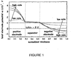
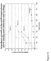
- Figure 1 is a schematic illustration of the local potential (voltage) at various locations across the normalized thickness of a conventional lithium-ion cell.
- the locations of the positive electrode, separator and negative electrode are indicated.
- a series of curves indicates the potential for different illustrative charge rates. Arrows in the figure indicate the trend for increasing rate. As the battery is charged at higher rates, the positive electrode potential is pushed to a higher potential and the negative electrode drops to a lower potential. At high rates, the potential at the negative electrode drops to below 0 V vs. Li/Li + and plating of lithium metal at the negative electrode occurs. Note that the potential of the separator changes little over a wide range of charge rates.
- FIG. 2 is a schematic illustration of the positive and negative electrode potentials of a conventional LiCoO 2 ("LCO")-graphite cell, which has a relatively high impedance (ca. 40 ⁇ -cm 2 ) over the entire state of charge.
- LCO LiCoO 2
- the negative electrode potential remains above the lithium plating potential.
- the negative electrode potential is driven so low that the negative potential drops below the lithium plating potential (0 V vs Li/Li + ). Lithium plating at the anode takes place under the conditions indicated by the arrow in Figure 2 .
- the high rate-constant current charge of a high-impedance cell results in the undesirable plating of lithium.
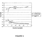
- FIG. 3 A low impedance Li-ion cell as described herein is illustrated in Figure 3 .
- the negative electrode does not plate lithium.
- Figure 3 shows the positive and negative electrode potentials for a LiFePO 4 ("LFP")-graphite cell with an exemplary total area specific impedance (ASI tot ) of about 12 ⁇ -cm 2 .
- ASI tot total area specific impedance
- the positive and negative electrodes represent the greatest contribution to the total area specific impedance (ASI tot ) of the cell.
- the impedance of the separator, and the various connecting metal parts of the cell such as the tabs, the current collector foils or grids and the electrode-current collector interfacial resistance generally contribute between about 10-20%, and typically about 15%, of the total area specific impedance (ASI tot ).
- the impedance of the negative electrode is at a minimum.
- the area specific impedance of the negative electrode is less than about 3.0 ⁇ -cm 2 , or less than about 2.5 ⁇ -cm 2 , or less than 2.0 ⁇ -cm 2 , or less than 1.8 ⁇ -cm 2 , or less than 1.5 ⁇ -cm 2 .
- a further feature of a high rate, low impedance Li-ion cell is that the positive electrode bears a predominant amount or even a major amount of the total cell impedance (ASI tot ), while the total cell impedance remains low.
- ASI tot the total cell impedance
- up to 70% of the cell impedance is localized at the positive electrode.
- the ratio of area specific impedance of the positive electrode (ASI c ) to the area specific impedance of the negative electrode (ASI a ) is greater than about three.
- the ratio of area specific impedance of the positive electrode (ASI c ) to the area specific impedance of the negative electrode (ASI a ) is in a range of about 3-10, or is greater than about 4, greater than about 5, greater than about 6, greater than about 7, greater than about 8, greater than about 9, or greater than about 10.
- the total area specific impedance of the cell is low and is typically less than 20 ⁇ -cm 2 .
- the total area specific impedance (ASI tot ) can be less than 18 ⁇ -cm 2 , or less than 16 ⁇ -cm 2 , or less than 14 ⁇ -cm 2 , or less than 12 ⁇ -cm 2 , or less than 10 ⁇ -cm 2 or less than 8 ⁇ -cm 2 .
- the smaller the value for the total area specific impedance (ASI tot ) the smaller the proportion of the total impedance required to be borne at the positive electrode in order to prevent lithium plating.
- Table 1 lists an exemplary relationship between total area specific impedance (ASI tot ) and the area specific impedance at the positive electrode (ASI c ) for an exemplary Li-ion cell according to one or more embodiments of the present invention.
- ASI tot ( ⁇ -cm 2 ) 8 10 12 14 16 18 20 ASI c /ASI a 3 4 5 6 7 9 10
- Li-ion cells achieve high charge rates in cells having thick electrode layers, e.g ., a positive electrode layer of about 50 ⁇ m to about 125 ⁇ m on one side of the current collector. While thicker electrode layers provide higher charge capacity, the thicker layers also typically increase the impedance of the electrodes (by, for example, increasing the distance and the tortuosity of the lithium diffusion pathway).
- the areal charge capacity is one-half of the measured areal capacity for the double-sided electrode, e.g., at least about 0.75 mA-hr/cm 2 .
- Li-ion cell having areal charge capacities of at least about 0.75 mA-hr/cm 2 , or about 1.0 mA-h/cm 2 or about 1.5 mA-hr/cm 2 are capable of high rate charge and discharge without plating lithium at the negative electrode.
- a high capacity Li-ion cell is charged and discharged at a high rate, e.g., greater than 2C, greater than 4C, or greater than 10C, or even at 20C, without significant capacity fade.
- the cell can be initially charged by the galvanostatic (constant current) method to target voltage, e.g., 3.6-3.8 V for a LiFePO 4 -C cell, using a high C-rate (2, 5, 10, or 20C.)
- target voltage e.g., 3.6-3.8 V for a LiFePO 4 -C cell, using a high C-rate (2, 5, 10, or 20C.
- a potentiostatic segment can be applied until the current decreases to a C/20 rate (CC-CV protocol or taper charge method), which is considered to be 'fully charged' or state of charge.
- the time to achieve state of charge is very fast, e.g., less than 15 minutes, with low levels of cell heating. This can be compared to a low charge rate of 1
- the inventors have found that the batteries made according to one or more embodiments as described herein show surprisingly low fade rate when charged at a high rate.
- high capacity lithium-ion cells show less than about 0.2% loss per cycle, about 0.1% loss per cycle, about 0.05% loss per cycle, and about 0.025% loss per cycle.
- the Li-ion cell charges at 4C-rate and reaches about 90%, or even about 95%, state of charge within 15 minutes.
- Other Li-ion cells charge at 10C-rate and achieve about 80%, or even about 90%, state of charge within 6 minutes.
- the Li-ion cells also possess superior discharge rate capabilities as compared to conventional Li-ion cells.
- Li-ion cells according to one or more embodiments of the present invention demonstrate 10C capacity of greater than about 70%, or about 80%, or about 90%, or even about 95% of nominal capacity measured at C/10.
- the lithium-ion battery can be charged to potentials well above the standard charging potential, in order to charge the battery more quickly.
- a conventional 4.2V lithium-ion battery such as one that contains LiCoO 2
- the maximum charging current is also limited by the potential at the positive electrode.
- a high potential at the positive electrode will cause electrolyte oxidation, which greatly decreases the lifetime of the battery.
- Lithium iron phosphate has a lower average voltage during charge.
- a positive electrode incorporating lithium iron phosphate as the active material can be polarized to a greater extent before reaching the electrolyte oxidation potential.
- transition metal phosphate positive electrode materials are charged using a larger overpotential with respect to the open-circuit voltage (OCV) because of the low average cell voltage and high stability of the positive electrode material in its delithiated state. As a result, there is no excess lithium in the positive electrode when the cell is in the fully charged state.
- conventional positive electrode materials using LiCoO 2 for example, cannot be charged to potentials greater than 4.2V because of its instability in the delithiated state.
- the larger overpotential at the positive electrode i.e., the potential above the standard charging potential, allows the cell to be charged at a high, constant current for a longer period of time before the charging current must be decreased or before the cell is placed on a potentiostatic, or constant voltage, hold.
- the larger overpotential is achievable at an absolute voltage that remains sufficiently low to avoid electrolyte oxidation at the positive electrode. Thus, the cell can be charged more quickly without danger of electrolyte oxidation.
- the overpotential capability of the positive electrode material is particularly useful when combined with a low-impedance negative electrode (or a higher positive electrode-to-negative electrode impedance ratio (ASI c /ASI a )), as described in herein. Note that a high impedance negative electrode alone would not be useful because lithium would plate onto the anode regardless of the positive electrode potential.
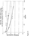
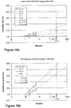
- the rate capability of a cell is determined by a constant current or constant power continuous discharge, which gives rise to a Ragone plot.
- the discharge energy density of the battery is at least about 85 Wh/kg at a power density of at least about 750 W/kg.
- Ragone plots are used to describe energy density during discharge, not charge. So other methods are used to describe the high charge capability of this invention.
- a Li-ion cell for which the resistance of the components contributing to the voltage drop at the negative electrode are minimized.
- Factors affecting the impedance (and hence rate capability) at the negative electrode itself during high-rate discharge include electrode thickness, bulk electronic conductivity, contact resistance between current collector and active material particles, average size of active material - typically carbon - particles, Li + diffusion coefficient in the active material, electrode porosity, pore size distribution and tortuosity, ionic conductivity of the liquid electrolyte, and transference number of Li + in the liquid electrolyte.
- the factors listed above that strongly affect the negative electrode's rate capability are equally important in the case of the positive electrode as well.
- a Li-ion battery capable of safe and long-term operation at a high rate of charge and discharge without a significant loss of power and capacity and a method of its manufacture is described in detail herein.
- the positive and negative electrodes are designed at the (1) active particle level, (2) electrode level, and (3) cell level to maximize rate, reduce impedance, in particular at the negative electrode, while maintaining a high charge capacity.
- the cell exhibits low impedance growth, which is useful to provide improved battery life, for example, in hybrid electric vehicle applications and other high demand applications.
- the cell is a high power battery that does not show significant impedance growth during high power cycling and/or high temperature and/or long term storage. Due to the long battery life required for hybrid electric vehicle applications, impedance growth becomes an important factor, especially toward the end of battery life.
- Conventional battery packs composed of multiple cells are often oversized, or provided initially with excess capacity, so that they can meet the performance requirements throughout the entire battery life. This oversizing disadvantageously adds to the weight, volume, and cost of the battery packs.
- cells as described herein exhibit low impedance growth, or even a decrease in impedance over time, allowing for their use in battery packs for hybrid electric vehicles with a lesser degree of oversizing than typical packs.
- a battery pack refers to a plurality of cells arranged in series, parallel, or a combination thereof.
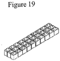
- Figure 10 shows an example of a battery pack having cells arranged in both series and parallel.
- the cells are connected in series to achieve a selected voltage for the total battery pack, e.g., to operate for an intended use (e.g., an HEV application may require a voltage of about 330V, while a motor starter may require about 36V).
- cells of a selected capacity are connected in parallel to achieve a selected current, e.g., the current required to operate the device for an intended use (e.g., for use in an HEV or for an application that requires high energy or high capacity).
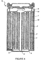
- the batteries as described herein are covered with an exterior member.
- the exterior member includes, for example, heat-shrinkable tubing, adhesive tape, metal film, paper, cloth, paint, and a plastic casing. Further, in some embodiments, at least part of the exterior member may be provided with a section that will change in color owing to heat, so that the thermal history in use can be seen.
- the battery pack described herein is provided with safety elements, such as a positive temperature coefficient resistor, a thermal fuse, a fuse and/or a circuit breaking element, as well as a safety circuit (a circuit that is for monitoring, for example, the voltage, the temperature, and the electric current of each battery and/or the set of the batteries, and, if necessary, the circuit has a function for breaking the current).
- safety elements such as a positive temperature coefficient resistor, a thermal fuse, a fuse and/or a circuit breaking element
- a safety circuit a circuit that is for monitoring, for example, the voltage, the temperature, and the electric current of each battery and/or the set of the batteries, and, if necessary, the circuit has a function for breaking the current.
- the battery pack is provided with, in addition to the positive electrode terminal and the negative electrode terminal of the set of the batteries, for example, a positive electrode terminal and a negative electrode terminal for each of the batteries, temperature detection terminals for the set of the batteries and for each of the batteries, and a current sensing terminal
- the battery pack may have a built-in voltage-converting circuit (e.g., a DC-DC converter).
- the connection between the batteries may be fixed by welding lead plates, or it may be fixed for easy detachability by using sockets or the like.
- the battery pack may be provided with a function for displaying, for example, the remaining capacity of the batteries, whether or not charging has been done, and how often the battery pack has been used.
- the cells described herein can be used in various devices.
- the cells described herein are used in applications requiring high power and/or long-term use with good electrochemical stability.
- Certain applications include, without limitation, hybrid electric vehicles, alternative energy storage (e.g., solar and wind), uninterrupted power systems, medical devices (e.g. defibrillators), and space vehicles (e.g., satellites).
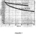
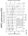
- the FreedomCAR Battery Test Manual describes a hybrid pulse power characterization (HPPC) test, which provides a measurement of dynamic power capability over a cell's useable charge and voltage range.
- the available energy of a pack depends on the shape of its HPPC curves, and how much its impedance grows over time. Packs for HEV applications are generally oversized to allow some increase of impedance over the lifetime of the pack and reduction of available energy.
- Typical packs engineered to meet the DOE "available energy" requirement contain, for example, 2000+ Wh of total energy.
- a pack made up of cells as described herein is projected to have an energy of only about 1400 Wh.
- the pack made up of cells as described herein is oversized to a lesser extent, e.g., initially including about 20%, and in some instances about 30% or about 40%, less energy than conventional packs, while still meeting performance objectives.
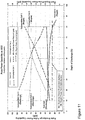
- the lower degree of oversizing for the cells as described herein is determined by comparing the cell power at the end of life with the power at the beginning of life.
- BSF battery size factor
- Conventional battery packs may increase the number of cells in order to maintain the required energy for a desired state of charge. This, of course, increases the size, weight and cost of the pack. Because the cells described herein can maintain current over a wide state of charge and discharge, in particular at high C rates, due to the low cell impedance, oversizing is not required.
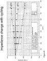
- the low impedance growth provided by cells as described herein is truly remarkable, and can actually result in a reduction in total impedance (ASI tot ).
- Reduction in impedance, as well as reduction in impedance growth has been demonstrated experimentally, as described in more detail in the Examples below.
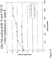
- a cell in cycling from 0 to 100% depth of discharge, a cell can exhibit an impedance decrease with cycling at moderate temperatures (25°C and 45°C), and only slight impedance increase with cycling at higher temperature (60°C).
- low impedance growth it is meant that the cell impedance increases by less than about 10% for every 1000 charge/discharge cycles at a temperature of up to 60°C.
- the cell impedance increases by less than about 9% or less than about 8%, for every 1000 charge/discharge cycles at a temperature of up to 60°C.
- low impedance growth is determined with deep discharge charge-discharge cycles, for example, greater than 50%, 60%, 70%, 80%, or 90% depth of discharge.
- deep discharge refers to 100% depth of discharge.
- Cells as described herein also can exhibit low total cell energy capacity decrease or low total cell energy decrease, another indicia of low impedance growth.
- the total cell energy or capacity decrease is not more than about 20% from the initial cell energy for every 500 charge-discharge cycles at a temperature of up to about 100°C.
- the total cell energy (or capacity) is determined with deep discharge charge-discharge cycles, as described above.
- FIG. 11 shows comparative HPPC performance results for a cell as described herein (solid lines) and two comparative lithium-ion batteries (long and short dashed lines).
- the two comparative cells exhibit higher pulse power, as exhibited by the HPPC curves being shifted upwards, presumably due to costly oversizing to allow the battery pack to meet performance requirements at the end of life, and a more rapid decrease in available energy with impedance growth.
- the available power at the beginning of life is no more than about 10% to about 30% greater than a predefined power at end of life, for example no more than about 30%, no more than about 25%, no more than about 20%, no more than about 15% or no more than about 10%.
- the available power at the beginning of life is about 10% to about 30% greater than a predefined power at end of life.
- the available power at the beginning of life is about 10% to about 20% greater than a predefined power at end of life.
- the beginning and end of life available power is determined with reference to HPPC curves. For example, the pulse power for a cell at a particular state of charge is determined at beginning of life.
- pulse power comparisons are performed at a 40-60% SOC (corresponding to 60-40% depth of discharge). In some embodiments, pulse power comparisons are performed at 40% SOC, 50% SOC or 60%SOC. In some embodiments, e.g., for hybrid electric vehicle applications, end of life is considered the point at which the available energy is 300 Wh.
- the HPPC curves shift down due to impedance growth.
- conventional systems must oversize to accommodate for the reduction in capacity due to the impedance growth.
- Oversizing e.g., by adding more cells to the pack
- this increase is shown by discharge and regen curves that are shifted upwards.
- Oversizing is required due to the loss of power that occurs with cycling and/or time. If there was no loss of power or energy with time, the pack could be sized with the exact minimum number of cells required to meet the energy and power requirements from the beginning-of-life. However, because batteries lose power with time and/or cycling, additional cells are required to allow for this degradation. Technologies that suffer from relatively large degrees of degradation require a greater degree of oversizing.
- the shape of the discharge and regen curves in the HPPC plot are also important in determining the amount of oversizing required for an application.
- the discharge and regen curves are steep, the available energy is a small fraction of the total energy of the pack. Accordingly, to ensure that the battery can produce the required discharge and regen pulses at any given moment, the battery must be operated in a narrow range of state-of-charge. As a consequence of operating within the narrow SOC range, a portion (in some embodiments, a majority) of the battery's energy is never used.
- the discharge and regen curves are relatively shallow or flat, the battery can be operated over a wide range of SOC. As a result, more of the battery's energy can be used.
- the battery is considered to have reached its end of life when it can no longer meet the discharge and regen pulse power requirements, over a the required range of state-of-charge for the application. For example, referring to the Freedom CAR requirements, when a battery can no longer meeting the pulse power requirements over a range of state-of-charge corresponding to 300 Wh available energy, the battery is considered to be at the end of life.
- end of life occurs as the battery loses discharge and/or regen pulse power capability.
- end of life also occurs as battery loses energy.
- loss of power is the cause for the battery to reach its end of life.
- the cells as described herein do not require as much oversizing to achieve a predefined end of life available energy requirement. Accordingly, the beginning of life available energy is smaller relative to the required end of life available energy requirement (i.e., the HPPC curves do not shift downward significantly). As such, smaller and more cost-effective cells and battery packs can be used for high power applications requiring long battery life.
- the HPPC discharge and regeneration curve of the cells as described herein are much flatter (smaller slope) than those of conventional lithium ion cells, the cells as described herein are able to meet the discharge and regen requirements over a wide range of state of charge.
- the low impedance growth of the cells described herein also imparts a unique cycle life model relative to conventional lithium ion cells.
- the impedance growth of the cells described herein is logarithmic with respect to time ( e.g ., months of storage or battery life) and/or cycles.
- the impedance growth of conventional lithium secondary cells is typically linear with respect to time. H.J. Ploehu, et al., "Solvent Diffusion Model for Aging of Lithium-Ion Battery Cells" J. Electrochem. Soc'y 151(3):A456-A462 (2004 ).
- the rate of increase in impedance (or decrease in capacity), as judged by the slope of the curve of impedance growth versus time, is higher as the battery nears end of life compared to the beginning of life. Accordingly, the decay increases as the battery ages.
- the rate of increase in impedance decreases over the course of time, which is a surprising and unexpected result.
- the impedance growth is initially relatively fast, but is followed by a slower rate of decay.
- the impedance growth curve becomes flatter (smaller slope) at later time points than at the beginning of battery life.
- a logarithmic cycle life model is identified by any art-recognized method, such as, for example, plotting the capacity loss or impedance growth versus time and evaluating the shape of the curve to determine if it follows a well-known logarithmic shape.
- the shape of the impedance growth curve is determined by performing a linear regression analysis of a semi-log plot of capacity loss or impedance growth versus time.
- the linear regression fit represents a good fit of the data as determined by standard analytical techniques (e.g., by comparison of R-square values for various models (e.g., power, quadratic, square root of time, logarithmic), where the model with the highest R-square value is selected for modeling the cycle life), a logarithmic rate of decay is demonstrated.
- the impedance growth is logarithmic for storage or cycling conditions less than or equal to about 55 °C, for example, about 45 °C, about 38 °C, or about 25 °C.
- the factors used to develop a low impedance battery as described herein also may contribute to low impedance growth.
- the choice of electrode material and/or the choice of electrolyte composition contribute to the low impedance growth of the cell.
- Specific electrode compositions for low impedance growth cells are described in more detail below.
- Specific electrolyte compositions for low impedance growth cells are described in more detail below.
- the electrode composition contains a lithium transition metal phosphate.
- the electrolyte composition contains LiPF 6 , ethylene carbonate and one or more of propylene carbonate, dimethyl carbonate, ethyl methyl carbonate, diethyl carbonate, and vinylene carbonate.
- an electrolyte composition is chosen in combination with electrode active materials to provide a cell that has low operating voltage, being less than about 4.2V, and a solid electrolyte interface (SEI) layer that is stable during high power and/or high temperature storage and/or cycling.
- the electrode active material defines the voltage of the cell; the difference between the potential (voltage) of the cathode and anode is the cell voltage.
- a low operating voltage is desirable because it allows for higher current charge without oxidizing the electrolyte, thus cells having a low open current voltage (OCV) used in conjunction with an electrolyte that is stable at the cell operating potential slows or reduces impedance growth.
- the cell exhibiting low impedance growth has an open circuit voltage (OCV) at 100% state of charge (SOC) of the cathode that is less than about 3.8 V, for example, about 3.4V, as shown in Figures 2 , 3 and 5 .
- OCV open circuit voltage
- SOC state of charge
- the cell exhibiting low impedance growth includes a cathode active material having an olivine structure and a formula LiMPO 4 , where M is one or more transition metals, and the material is doped or undoped at the lithium site.
- Lithium iron phosphate has a low OCV that is less than about 3.8V. It is believed that lithium ion cells using positive electrode materials such as LiFePO 4 undergo less substantial volume change on charge and discharge than those using materials such as LiCoO 2 , and therefore may exhibit somewhat less deterioration and corresponding impedance growth over long term cycling.
- positive electrode materials such as LiFePO 4 described herein experience less mechanical stress over time, due to repeated intercalation and de-intercalation of lithium. In conventional battery electrode materials, the particles break apart, thus creating higher-impedance interfaces. Cells employing electrode materials as described herein do not suffer from this "electrochemical grinding" mechanism. However, it was unexpected that cells made with LiFePO 4 cathode materials could provide sufficiently low impedance growth for use in hybrid electric vehicle applications. Additional factors that may contribute to the low impedance growth exhibited by a cell as described herein include beneficial surface reactions at the cathode that decrease over time with use, or more complete infiltration of the cathode material by the electrolyte, which improves during use. In some embodiments, the cell exhibiting low impedance growth has an anode active material that includes a natural or synthetic graphite material.
- the nonaqueous electrolyte secondary battery includes a battery element having an elongated cathode and an elongated anode, which are separated by two layers of an elongated microporous separator which are tightly wound together and placed in a battery can.
- a typical spiral electrode secondary cell is shown in Figure 4 (reproduced from United States Patent No. 6,277,522 ).
- the secondary cell 15 includes a double layer of anode material 1 coated onto both sides of an anode collector 10, a separator 2 and a double layer of cathode material 3 coated onto both sides of cathode collector 11 that have been stacked in this order and wound to make a spiral form.
- the spirally wound cell is inserted into a battery can 5 and insulating plates 4 are disposed at upper and lower surfaces of the spirally wound cell.
- a cathode lead 13 from anode collector 11 provides electrical contact with cover 7.
- An anode lead 12 is connected to the battery can 5.
- An electrolytic solution is added to the can.
- a Li-ion battery capable of safe, long-term operation at a high rate of charge and discharge and low impedance growth, and a method of its manufacture includes one or more of the following features.
- the positive electrode includes a lithium-transition metal-phosphate compound as the electroactive material.
- the lithium-transition metal-phosphate compound may be optionally doped with a metal, metalloid, or halogen.
- the positive electroactive material is an olivine structure compound LiMPO 4 , where M is one or more of V, Cr, Mn, Fe, Co, and Ni, in which the compound is optionally doped at the Li, M or O-sites. Deficiencies at the Li-site are compensated by the addition of a metal or metalloid, and deficiencies at the O-site are compensated by the addition of a halogen.
- the positive active material is a thermally stable, transition-metal-doped lithium transition metal phosphate having the olivine structure and having the formula (Li 1-x Z x )MPO 4 , or Li(M 1 - x Z x )PO 4 where M is one or more of V, Cr, Mn, Fe, Co, and Ni, and Z is a non-alkali metal dopant such as one or more of Ti, Zr, Nb, Al, Ta, W or Mg, and x ranges from 0.005 to 0.05.
- the electroactive material is (Li 1-x Z x )MPO 4 , where Z is Zr, Nb or Ti.
- Doped lithium iron phosphate compounds may be prepared from starting materials of lithium salts, iron compounds and phosphorous salts including, but not limited to, lithium carbonate, ammonium phosphate and iron oxalate, to which a low additional concentration of dopant metal such as Mg, Al, Ti, Fe, Mn, Zr, Nb, Ta and W have been added, typically as a metal oxide or metal alkoxide.
- the powder mixture is heated under a low oxygen environment at a temperature of 300 °C to 900 °C. These compounds exhibit increased electronic conductivity at and near room temperature, which is particularly advantageous for their use as lithium storage materials. Further details regarding the composition and preparation of these compounds are found in United States Published Application 2004/0005265 (corresponding to U.S. Patent Application No. 10/329,046 , entitled "Conductive Lithium Storage Electrode”).
- the alkali transition metal phosphates include those described in U.S. Patent Application No. 11/396,515, filed April 3, 2006 entitled "Nanoscale Ion Storage Materials".
- Examples include nanoscale ordered or partially disordered structures of the olivine (A x MPO 4 ), NASICON (A x (M',M") 2 (PO 4 ) 3 ), VOPO 4 , LiVPO 4 F, LiFe(P 2 O 7 ) or Fe 4 (P 2 O 7 ) 3 structure types, wherein A is an alkali ion, and M, M' and M" are metals.
- the alkali transition metal phosphate composition has the formula Li M PO 4 ( i.e., an olivine structure type), where M is one or more transition metals. In some embodiments, M is one or more of V, Cr, Mn, Fe, Co and Ni. In certain embodiments, the alkali transition metal phosphate composition is an ordered olivine (Li 1-x MXO 4 ), where M is at least one first row transition metal ( e.g., one or more of V, Cr, Mn, Fe, Co and Ni), and x can range from zero to one, during lithium insertion and deinsertion reactions. In some embodiments, M is Fe. In the as-prepared state, x is typically about one.
- the special properties of the ion storage materials may be augmented by doping with foreign ions, such as metals or anions.
- Such materials are expected to exhibit similar behavior to that demonstrated herein for Li 1- x FePO 4 at the nanoscale, based on the scientific principles underlying such behavior.
- doping is not required for a material to exhibit special properties at the nanoscale.
- the lithium transition metal phosphate material has an overall composition of Li 1-x-z M 1-z PO 4 , where M comprises at least one first row transition metal selected from the group consisting of Ti, V, Cr, Mn, Fe, Co and Ni, where x is from 0 to 1 and z can be positive or negative.
- M includes Fe, and z is between about 0.15 and -0.15.
- the material can exhibit a solid solution over a composition range of 0 ⁇ x ⁇ 0.30, for example 0 ⁇ x ⁇ 0.15.
- the material exhibits a stable solid solution over a composition range of x between 0 and at least about 0.15. In some embodiments, the material exhibits a stable solid solution over a composition range of x between 0 and at least about 0.07 or between 0 and at least about 0.05 at room temperature (22-25 °C).
- the material can also exhibit a stable solid solution at low lithium content; e.g., where 1 ⁇ x ⁇ 0.8 or where 1 ⁇ x ⁇ 0.9, or where 1 ⁇ x ⁇ 0.95.
- the positive electroactive material has a lithium-rich transition metal phosphate phase and a lithium-poor transition metal phosphate phase.
- the lithium-rich transition metal phosphate phase has the composition Li y MPO 4 and the lithium-poor transition metal phosphate phase has the composition Li 1-x MPO 4 , and 0.02 ⁇ y ⁇ 0.2 and 0.02>x>0.3 at room temperature (22-25°C).
- the material can exhibit a solid solution over a composition range of 0 ⁇ x ⁇ 0.15 and 0.02 ⁇ y ⁇ 0.10.
- the nanoscale positive electrode electroactive materials are also based on the alkali transition metal phosphates, such as those described in U.S. Patent Application No. 10/329,046 .
- the electroactive material has an overall composition of Li x Fe 1-a M" a PO 4 , and a conductivity at 27° C, of at least about 10 -8 S/cm.
- the conductivity is at least about at least about 10 -7 S/cm, in other cases, at least about 10 -6 S/cm, in yet other cases, at least about 10 -5 S/cm, in still other cases, at least about 10 -4 S/cm, in some cases, at least about 10 -3 S/cm, and in other cases, at least about 10 -2 S/cm.
- the alkali transition metal phosphate composition has an overall composition of Li x Fe 1-a M" a PO y , the compound having a gravimetric capacity of at least about 80 mAh/g while the device is charging/discharging at greater than about C rate.
- the capacity is at least about 100 mAh/g, or in other embodiments, at least about 120 mAh/g, in some embodiments, at least about 150 mAh/g, and in still other embodiments, at least about 160 mAh/g.
- the present invention can, in some embodiments, also provide a capacity up to the theoretical gravimetric capacity of the compound.
- the alkali transition metal phosphate composition has an overall composition of Li x-a M" a FePO 4 .
- the alkali transition metal phosphate composition has an overall composition of Li x-a M" a FePO 4 , and a conductivity at 27° C of at least about 10 -8 S/cm.
- the conductivity is at least about at least about 10 -7 S/cm, in other cases, at least about 10 -6 S/cm, in yet other cases, at least about 10 -5 S/cm, in still other cases, at least about 10 -4 S/cm, and in some cases, at least about 10 -3 S/cm, and in further cases, at least about 10 -2 S/cm.
- the alkali transition metal phosphate composition has an overall composition of Li x-a M" a FePO 4 , the compound having a gravimetric capacity of at least about 80 mAh/g while the device is charging/discharging at greater than about C rate.
- the capacity is at least about 100 mAh/g, or in other embodiments, at least about 120 mAh/g; in some embodiments, at least about 150 mAh/g and in still other embodiments, at least about 170 mAh/g.
- the present invention can, in some embodiments, also provide a capacity up to the theoretical gravimetric capacity of the compound.
- a composition comprising a compound with a formula A x (M' 1-a M" a ) y (XD 4 ) z , A x (M' 1-a M" a ) y (DXD 4 ) z , or A x (M" 1-a M” a ) y (X 2 D 7 ) z , has a conductivity at about 27° C.
- A is at least one of an alkali metal and hydrogen
- M' is a first-row transition metal
- X is at least one of phosphorus, sulfur, arsenic, molybdenum and tungsten
- M" is any of a Group IIA, IIIA, IVA, VA, VIA, VIIA, VIIIA, IB, IIB, IIIB, IVB, VB, and VIB metal
- D is at least one of oxygen, nitrogen, carbon, or a halogen
- x, y, and z have values such that x plus the quantity y(1-a) times a formal valence or valences of M', plus the quantity ya times a formal valence or valence of M", is equal to z times a formal valence of the XD 4 , X 2 D 7 , or DXD 4 group.
- x, y, and z are typically greater than 0.
- the conductivity of the compound can be at least about 10 -5 S/cm, at least about 10 -4 S/cm, and, in some cases, at least about 10 -2 S/cm.
- A is lithium and x/(x+y+z) can range from about zero to about one third, or about zero to about two thirds.
- X is phosphorus, while in other embodiments, M' is iron.
- M" can be any of aluminum, titanium, zirconium, niobium, tantalum, tungsten, or magnesium. M" can be substantially in solid solution in the crystal structure of the compound.
- the compound has at least one of an olivine (e.g., AMPO 4 ), NASICON (e.g ., A 2 M 2 (PO 4 ) 3 ), VOPO 4 , LiFe(P 2 O 7 ) or Fe 4 (P 2 O 7 ) 3 structure, or mixtures thereof.
- an olivine e.g., AMPO 4
- NASICON e.g ., A 2 M 2 (PO 4 ) 3
- VOPO 4 LiFe(P 2 O 7 ) or Fe 4 (P 2 O 7 ) 3 structure, or mixtures thereof.
- the nanoscale electrode compound is LiFePO 4 .
- M" is at least partially in solid solution in the crystal structure of the compound at a concentration of at least 0.01 mole % relative to the concentration of M', the balance appearing as an additional phase, at least 0.02 mole % relative to the concentration of M', the balance appearing as an additional phase, and in yet other embodiments, at least 0.05 mole % relative to the concentration of M', the balance appearing as an additional phase and, in still other embodiments, at a concentration of at least 0.1 mole % relative to the concentration of M', the balance appearing as an additional phase.
- the alkali transition metal phosphate composition has an overall composition of (A 1-a M" a ) x M' y (XD 4 ) z , (A 1-a M" a ) x M' y (DXD 4 ) z , or (A 1-a M" a ) x M' y (X 2 D 7 ), and has a conductivity at 27° C of at least about 10 -8 S/cm, wherein A is at least one of an alkali metal and hydrogen, M' is a first-row transition metal, X is at least one of phosphorus, sulfur, arsenic, molybdenum, and tungsten, M" any of a Group IIA, IIIA, IVA, VA, VIA, VIIA, VIIIA, IB, IIB, IIIB, IVB, VB, and VIB metal, D is at least one of oxygen, nitrogen, carbon, or a halogen, 0.0002 ⁇ a>0.1, and x, y,
- the conductivity of the compound can be at least about 10 -5 S/cm, at least about 10 -4 S/cm, and, in some cases, at least about 10 -2 S/cm.
- A is lithium and x/(x+y+z) can range from about zero to about one third.
- X is phosphorus, while in other embodiments, M' is iron.
- M" can be any of aluminum, titanium, zirconium, niobium, tantalum, tungsten, or magnesium. M" can be substantially in solid solution in the crystal structure of the compound.
- the compound has at least one of an olivine, NASICON, VOPO 4 , LiFe(P 2 O 7 ) or Fe 4 (P 2 O 7 ) 3 structure, or mixtures thereof.
- the compound is LiFePO 4 .
- M" is at least partially in solid solution in the crystal structure of the compound at a concentration of at least 0.01 mole % relative to the concentration of M', the balance appearing as an additional phase, at least 0.02 mole % relative to the concentration of M', the balance appearing as an additional phase, and in yet other embodiments, at least 0.05 mole % relative to the concentration of M', the balance appearing as an additional phase and, in still other embodiments, at a concentration of at least 0.1 mole % relative to the concentration of M', the balance appearing as an additional phase.
- the alkali transition metal phosphate composition has a suitable electronic conductivity greater than about 10 -8 S/cm.
- the alkali transition metal phosphate composition can be a composition of Li x (M 1-a M" a )PO 4 or L x-a M" a M'PO 4 , and can crystallize in the ordered-olivine or triphylite structure, or a structure related to the ordered olivine or triphylite structure with small displacements of atoms without substantial changes in the coordination number of anions around cations, or cations around anions.
- Li .+ substantially occupies the octahedral site typically designated as M1
- a substantially divalent cation M' substantially occupies the octahedrally-coordinated site typically designated as M2, as described in the olivine structure given in " Crystal Chemistry of Silicate Minerals of Geophysical Interest," by J. J. Papike and M. Cameron, Reviews of Geophysics and Space Physics, Vol. 14, No. 1, pages 37-80, 1976 .
- the exchange of Li and the metal M' between their respective sites in a perfectly ordered olivine structure is allowed so that M' may occupy either site.
- M' is typically one or more of the first-row transition metals, V, Cr, Mn, Fe, Co, or Ni.
- M" is typically a metal with formal valence greater than I+as an ion in the crystal structure.
- M', M", x, and a are selected such that the electroactive material is a crystalline compound that has in solid solution charge compensating vacancy defects to preserve overall charge neutrality in the compound.
- this condition can be achieved when a times the formal valence of M" plus (1-a) times the formal valence of M' plus x is greater than 3+, necessitating an additional cation deficiency to maintain charge neutrality, such that the crystal composition is Li x (M' 1-a-y M" a vac y )PO 4 or Li x-a M" a M' y vac y PO 4 , where vac is a vacancy.
- the dopant can be supervalent and can be added under conditions of temperature and oxygen activity that promote ionic compensation of the donor, resulting in nonstoichiometry.
- the vacancies can occupy either M1 or M2 sites.
- the compound When x ⁇ 1, the compound also has additional cation vacancies on the M1 site in a crystalline solid solution, said vacancies being compensated by increasing the oxidation state of M" or M'.
- a suitable concentration of said cation vacancies should be greater than or equal to 10 18 per cubic centimeter.
- the alkali transition metal phosphate composition has an olivine structure and contains in crystalline solid solution, amongst the metals M' and M", simultaneously the metal ions Fe 2+ and Fe 3+ , Mn 2+ and Mn 3+ , Co 2+ and Co 3+ , Ni 2+ and Ni 3+ , V 2+ and V 3+ , or Cr 2+ and Cr 3+ , with the ion of lesser concentration being at least 10 parts per million of the sum of the two ion concentrations.
- the alkali transition metal phosphate composition has an ordered olivine structure and A, M', M", x, and a are selected such that there can be Li substituted onto M2 sites as an acceptor defect.
- typical corresponding crystal compositions are Li x (M' 1-a-y M" a Li y )PO 4 or Li x-a M" a M' 1-y Li y PO 4 .
- the subvalent Li substituted onto M2 sites for M' or M" can act as an acceptor defect.
- a suitable concentration of said Li on M2 sites should be greater than or equal to 10 18 per cubic centimeter.
- the nanoscale electrode material is a p-type semiconducting composition, for example Li x (M' 1-a M" a )PO 4 , Li x M" a M'PO 4 , Li x( M' 1-a-y M" a vac y )PO 4 , Li x-a M" a M' 1-y vac y PO 4 , Li x (M' 1-a-y M" a Li y )PO 4 or Li x-a M" a M' 1-y Li y PO 4 .
- M is a group IIA, IIIA, IVA, VA, VIA, VIIA, VIIIA, IB, IIB, IIIB, IVB, VB, and VIB element of the Periodic Table (catalog number S-18806, published by the Sargent-Welch company in 1994).
- Magnesium is an example of a dopant from Group IIA
- Y is an example of a dopant from Group IIIA
- Ti and Zr are examples of dopants from Group IVA
- Nb and Ta are examples of dopants from Group VA
- W is an example of a dopant from Group VIA
- Fe is an example of a metal from Group VIIIA
- Al is an example of a dopant from Group IIIB.
- x can have a value between zero and 1.1 in the initially prepared material. During its use as a lithium ion storage compound, x can vary between about zero and about 1.1. In the nanoscale materials described herein, a can have a value between about 0.0001 and 0.1. In some embodiments, out of the total amount a of M", at least 0.0001 is in solid solution in the crystalline structure of the compound.
- M' is Fe and the solubility of M" in the lattice can be improved if M" has an ionic radius, in octahedral coordination, that is less than that of Fe 2+ .
- Achieving solid solubility sufficient to increase the electronic conductivity above 10 -8 S/cm can require that processing conditions (for example, temperature, atmosphere, starting materials) allow M" to be stabilized in a particular valence state that would provide an ionic radius less than that of Fe 2+ .
- the M" ion may occupy the M1 site, or it may preferentially occupy the M2 site and cause Fe 2+ or Fe 3+ , which would normally occupy the M2 site, to occupy the M1 site.
- M" typically has an ionic radius that is less than the average ionic radius of ions M' at the Li concentration x at which the compound is first synthesized.
- Electrochemical insertion and removal can later change the valence distribution amongst the M' and M" ions.
- M" can be in the desired valence state and concentration by adding, to the starting material, a salt of M" having the desired final valence.
- the desired valence distribution amongst metals M' and M" can be obtained by synthesizing or heat treating under appropriate conditions of temperature and gas atmosphere. For example, if M' is Fe, heat treatment should be conducted under temperature and atmosphere conditions that preserve a predominantly 2+ valence state, although some Fe 3+ is allowable and can even be beneficial for increasing conductivity.
- the olivine composition according to some embodiments of the present invention may have a lithium deficiency that can result in a Li x-a M" a M'PO 4 crystal composition.
- M are not limited to those Groups of the Periodic Table that were previously identified, rather, M" can be any metal that satisfies the above requirements of size and valence.
- M may be Mg 2+ , Mn 2+ , Fe 3+ , Al 3+ , Ce 3+ , Ti 4+ , Zr 4+ , Hf 4+ , Nb 5+ , Ta 5+ , W 4+ , W 6+ , or combinations thereof.
- the lithium transition-metal phosphate compounds (e.g., doped or undoped LiFeO 4 ) can be prepared with a markedly smaller particle size and much larger specific surface area than previously known positive active materials, such as LiCoO 2 , LiNiO 2 or LiMn 2 O 4 and, thus improved transport properties. Improved transport properties reduce impedance and may contribute to low impedance growth.
- the positive active material consists of powder or particulates with a specific surface area of greater than about 10 m 2 /g, or greater than about 15 m 2 /g, or greater than about 20 m 2 /g, or even greater than about 30 m 2 /g.
- Li-ion batteries made from such materials have inferior safety and stability characteristics due to a combination of the high oxidation potential and low inherent thermal stability of these conventional materials in their partially or fully delithiated form, such as that existing in a partially or fully charged Li-ion battery.
- LiFeO 4 having the olivine structure and made in the form of very small, high specific surface area particles is exceptionally stable in delithiated form even at elevated temperatures and in the presence of oxidizable organic solvents, e.g., electrolytes, thus enabling a safer Li-ion battery having a very high charge and discharge rate capability.
- the small-particle-size, high specific-surface-area LiFePO 4 material exhibits not only high thermal stability, low reactivity and high charge and discharge rate capability, but it also exhibits excellent retention of its lithium intercalation and deintercalation capacity during many hundreds, or even thousands, of high-rate cycles.
- useful electrode materials include nanoscale ion storage materials, for example, nanoscale alkaline transition metal phosphates having the formula LiMPO 4 , where M is one or more transition metals.
- the nanoscale alkaline transition metal phosphate is doped at the Li site.
- the nanoscale alkaline transition metal phosphate is doped at the M site. It has been unexpectedly discovered that these ion storage materials having sufficiently small size scale and correspondingly high surface to volume ratio or specific surface area provide fundamentally different physical properties compared to their conventional coarse-grained counterparts.
- the nanoscale materials are compositionally and structurally distinct from, and provide different and improved electrochemical utility and performance compared to, the coarse-grained materials.
- the difference in relevant physical properties arises because the nanoscale materials are sufficiently small in at least one dimension (for instance, the diameter of an equi-axed particle, the diameter of a nanorod, or the thickness of a thin film) that they have different defect and thermodynamic properties.
- These nanoscale ion storage materials exhibit outstanding electrochemical performance for use in primary or secondary storage batteries, in particular providing a very high rate capability, while providing a large fraction of the intrinsic charge capacity and energy density of the material.
- the nanoscale ion storage material has a BET (Brunauer-Emmett-Teller method) specific surface area of at least about 20 m 2 /g, for example, at least about 25 m 2 /g, at least about 30 m 2 /g, at least about 35 m 2 /g, at least about 40 m 2 /g, at least about 45 m 2 /g, or at least about 50 m 2 /g.
- BET Brunauer-Emmett-Teller method
- the material includes approximately equi-axed particles having an "equivalent spherical particle size" (number-averaged mean particle diameter that would result in the measured surface area if the material were in the form of identically-sized spherical particles) of about 100 nm or less, for example, about 75 nm or less, about 70 nm or less, about 60 nm or less, about 50 nm or less, about 45 nm or less, about 40 nm or less, or about 35 nm or less.
- "equivalent spherical particle size" number-averaged mean particle diameter that would result in the measured surface area if the material were in the form of identically-sized spherical particles
- the material includes anisometric particles or a thin film or coating having a smallest cross-sectional dimension that is, on a number-averaged basis to provide a mean value, about 100 nm or less, for example, about 75 nm or less, about 70 nm or less, about 60 nm or less, about 50 nm or less, about 45 nm or less, about 40 nm or less, or about 35 nm or less.
- These dimensions can be measured using various methods, including direct measurement with an electron microscope of the transmission or secondary-electron type, or with atomic force microscopy.
- Such nanoscale ion storage materials are described in more detail in U.S. Application No. 10/329,046 , supra.
- the nanoscale electroactive materials described herein are prepared from conventional materials by size-reduction processes (e.g ., milling) to reduce the particle dimensions into the desired range.
- size-reduction processes e.g ., milling
- this can be a highly energy-intensive process.
- the materials also can be synthesized in the nanoscale state, by methods including, but not limited to, solid-state reactions between metal salts, wet-chemical methods, such as co-precipitation, spray-pyrolysis, mechanochemical reactions, or combinations thereof.
- Nanoscale materials with the desired particle sizes and specific surface areas are obtained by using homogeneous reactants, minimizing the reaction or crystallization temperature (in order to avoid particle coarsening), and avoiding formation of liquid phases in which the product is highly soluble (which also tends to lead to particle coarsening).
- Specific processing conditions can typically be established for a given process without undue experimentation by those skilled in the art. Further details regarding the composition and preparation of these compounds are found in United States Patent Application No. 11/396,515 , supra.
- nanoscale electroactive materials are prepared by non-equilibrium, moderate temperature techniques, such as wet-chemical or low temperature solid-state reactions or thermochemical methods.
- the materials thus prepared can acquire properties such as increased nonstoichiometry and disorder and increased solubility for dopants because they are synthesized in a metastable state or because kinetic pathways to the final product differ from those in conventional high temperature processes.
- Such disorder in the nanoscale form can also be preserved substantially under electrochemical use conditions and provide benefits as described herein.
- the active material and a conductive additive are combined to provide an electrode layer that permits rapid lithium diffusion throughout the layer.
- a conductive additive such as carbon or a metallic phase is included in order to improve its electrochemical stability, reversible storage capacity, or rate capability.
- Exemplary conductive additives include graphite, carbon black, acetylene black, vapor grown fiber carbon ("VGCF”) and fullerenic carbon nanotubes. Conductive diluents are present in a range of about 1%-5% by weight of the total solid composition of the positive electrode.
- the positive electrode (cathode) is manufactured by applying a semi-liquid paste containing the cathode active compound and conductive additive homogeneously dispersed in a solution of a polymer binder in an appropriate casting solvent to both sides of a current collector foil or grid and drying the applied positive electrode composition.
- a metallic substrate such as aluminum foil or expanded metal grid is used as the current collector.
- an adhesion layer e.g ., thin carbon polymer intercoating, may be applied.
- Exemplary adhesion layers include, without limitation, those described in U.S. Patent Application No. 11/515,633 , entitled “Nanocomposite Electrodes and Related Devices," filed September 5, 2006.
- the dried layers are calendared to provide layers of uniform thickness and density.
- the binder used in the electrode may be any suitable binder used as binders for non-aqueous electrolyte cells.
- Exemplary materials include a polyvinylidene fluoride (PVDF)-based polymers, such as poly(vinylidene fluoride) (PVDF) and its co- and terpolymers with hexafluoroethylene, tetrafluoroethylene, chlorotrifluoroethylene, poly(vinyl fluoride), polytetrafluoroethylene (PTFE), ethylene-tetrafluoroethylene copolymers (ETFE), polybutadiene, cyanoethyl cellulose, carboxymethyl cellulose and its blends with styrene-butadiene rubber, polyacrylonitrile, ethylene propylene diene terpolymers (EPDM), styrene-butadiene rubbers (SBR), polyimides, ethylene
- the positive electrode containing the positive electroactive material has a specific surface area of the electrode measured using the nitrogen adsorption Brunauer-Emmett-Teller (BET) method after the densification or calendaring step that is greater than 10 m 2 /g or greater than 20 m 2 /g.
- a positive electrode can have a thickness of less than 125 ⁇ m, e.g., between about 50 ⁇ m to 125 ⁇ m, or between about 80 ⁇ m to 100 ⁇ m on each side of the current collector, and a pore volume fraction between about 40 and 70 vol. %.
- the active material is typically loaded at about 10-20 mg/cm 2 , and typically about 11-15 mg/cm 2 .
- a thicker electrode layer provides greater total capacity for the battery.
- thicker layers also increase the electrode impedance.
- the present inventors have surprisingly discovered that high capacity, thick layers may be used in a low impedance (high rate) cell. Use of a high specific surface area active material, while maintaining adequate pore volume, provides the desired capacity without increasing impedance to unacceptably high levels.
- the electroactive material of the positive electrode includes a material that, while of high electronic conductivity, does not vary its conductivity by more than a factor of five, or factor of two, over the entire charge cycle.
- This feature of the Li-ion cell is contrasted with conventional electroactive positive electrode materials such as LiCoO 2 , LiNiO 2 or LiMn 2 O 4 for which conductivity increases dramatically once delithiation during charging occurs.
- the dramatic increase in conductivity of the electroactive material of the positive electrode contributes to a decrease in impedance.
- an electroactive material of the present cells exhibit only moderate increases in conductivity, so that its contribution to impedance is more moderate.
- the selection criteria for an anode are at two levels, the particle level and the electrode level. At the particle level, the particle size and the Li diffusion coefficient of the particle are selection criteria.
- the negative active material is a carbonaceous material.
- the carbonaceous material may be non-graphitic or graphitic.
- a small-particle-size, graphitized natural or synthetic carbon can serve as the negative active material.
- graphitic materials such as natural graphite, spheroidal natural graphite, mesocarbon microbeads and carbon fibers, such as mesophase carbon fibers, are preferably used.
- the carbonaceous material has a numerical particle size (measured by a laser scattering method) that is smaller than about 25 ⁇ m, or smaller than about 15 ⁇ m, or smaller than about 10 ⁇ m, or even less than or equal to about 6 ⁇ m.
- the smaller particle size reduces lithium diffusion distances and increases rate capability of the anode, which is a factor in preventing lithium plating at the anode. In those instances where the particle is not spherical, the length scale parallel to the direction of lithium diffusion is the figure of merit. Larger particle sized materials may be used if the lithium diffusion coefficient is high.
- the diffusion coefficient of MCMB is ⁇ 10 -10 cm 2 /s.
- Artificial graphite has a diffusion coefficient of ⁇ 10 -8 cm 2 /s.
- the negative active material consists of powder or particulates with a specific surface area measured using the nitrogen adsorption Brunauer-Emmett-Teller (BET) method to be greater than about 2 m 2 /g, or 4 m 2 /g, or even about 6 m 2 /g.
- BET Brunauer-Emmett-Teller
- the active material and a conductive additive are combined to provide an electrode layer that permits rapid lithium diffusion throughout the layer.
- a conductive additive such as carbon or a metallic phase may also be included in the negative electrode.
- Exemplary conductive additives include graphite, carbon black, acetylene black, vapor grown fiber carbon ("VGCF”) and fullerenic carbon nanotubes. Conductive diluents are present in a range of about 0%-5% by weight of the total solid composition of the negative electrode.
- the negative electrode (anode) of the battery is manufactured by preparing a paste containing the negative active material, such as graphitic or non-graphitic carbon, and a conductive carbon additive homogeneously suspended in a solution of a polymer binder in a suitable casting solvent.
- the paste is applied as a uniform-thickness layer to a current collector and the casting solvent is removed by drying.
- a metallic substrate such as copper foil or grid is used as the negative current collector.
- an adhesion promoter e.g ., oxalic acid, may be added to the slurry before casting.
- the binder used in the negative electrode may be any suitable binder used as binders for non-aqueous electrolyte cells.
- Exemplary materials include a polyvinylidene fluoride (PVDF)-based polymers, such as poly(vinylidene fluoride) (PVDF) and its co- and terpolymers with hexafluoroethylene, tetrafluoroethylene, chlorotrifluoroethylene, poly(vinyl fluoride), polytetrafluoroethylene (PTFE), ethylene-tetrafluoroethylene copolymers (ETFE), polybutadiene, cyanoethyl cellulose, carboxymethyl cellulose and its blends with styrene-butadiene rubber, polyacrylonitrile, ethylene propylene diene terpolymers (EPDM), styrene-butadiene rubbers (SBR), polyimides, ethylene-vinyl acetate copolymers.
- PVDF polyvinylidene fluoride
- PVDF poly(vinylidene fluoride)
- PTFE polytetraflu
- the negative electrode can have a thickness of less than about 75 ⁇ m, e.g ., between about 20 ⁇ m to about 65 ⁇ m, or between about 40 ⁇ m to about 55 ⁇ m on both sides of the current collector, and a pore volume fraction between about 20 and about 40 vol. %.
- the active material is typically loaded at about 5-20 mg/cm 2 , or about 4-5 mg/cm 2 .
- a thicker electrode layer provides greater total capacity for the battery.
- thicker layers also increase the electrode impedance by reducing the ease of lithium diffusion into the anode.
- the present inventors have surprisingly discovered that high capacity, thick layers may be used in a low impedance cell through selection of active materials as indicated above and maintaining adequate pore volume.
- a nonaqueous electrolyte includes an appropriate lithium salt, such as, for example, LiPF 6 , LiBF 4 , LiAsF 6 , or lithium bis(trifluoromethylsulfonimide) (LiTFMSI), lithium bis(oxalatoborate) (LiBOB), or lithium bis(pentafluoroethylsulfonyl)imide (LiBETI) dissolved in a nonaqueous solvent.
- LiTFMSI lithium bis(trifluoromethylsulfonimide)
- LiBOB lithium bis(oxalatoborate)
- LiBETI lithium bis(pentafluoroethylsulfonyl)imide
- One or more functional additives such as, for example, CO 2 , vinylene carbonate, ethylene sulfite, ethylene thiocarbonate, dimethyl dicarbonate, spirodicarbonate and propane sultone, can be included to modify the solid-electrolyte interface/interphase (SEI) that forms on the electrodes, particularly negative carbon electrodes.
- SEI solid-electrolyte interface/interphase
- the electrolyte may be infused into a porous separator that spaces apart the positive and negative electrodes.
- a microporous electronically insulating separator is used.
- Li-ion battery electrolytes notably a family of cyclic carbonate esters such as ethylene carbonate (EC), propylene carbonate (PC), butylene carbonate (BC), and vinylene carbonate (VC), and their chlorinated or fluorinated derivatives, and a family of acyclic dialkyl carbonate esters, such as dimethyl carbonate (DMC), diethyl carbonate (DEC), ethylmethyl carbonate (EMC), dipropyl carbonate, methyl propyl carbonate, ethyl propyl carbonate, dibutyl carbonate, butylmethyl carbonate, butylethyl carbonate and butylpropyl carbonate.
- DMC dimethyl carbonate
- DEC diethyl carbonate
- EMC ethylmethyl carbonate
- dipropyl carbonate dipropyl carbonate
- methyl propyl carbonate ethyl propyl carbonate
- dibutyl carbonate butylmethyl carbonate, but
- solvents proposed as components of Li-ion battery electrolyte solutions include methyl acetate (MA), ethyl acetate (EA), methyl formate (MF), propyl acetate (PA), methyl butyrate (MB), ethyl butyrate (EB), ⁇ -butyrolactone ( ⁇ -BL), dimethoxyethane, tetrahydrofuran, 2-methyl tetrahydrofuran, 1,3-dioxolane, 4-methyl-1,3-dioxolane, diethyl ether, sulfolane, methylsulfolane, acetonitrile, propiononitrile, ethyl acetate, methyl propionate, ethyl propionate and the like. These nonaqueous solvents are typically used as multicomponent mixtures.
- a cell exhibiting low impedance growth employs an electrolyte having the following composition: about 0.8 M to about 1.5 M LiPF 6 in an organic solvent made up of about 30 wt% to about 70 wt% ethylene carbonate, about 0 wt% to about 20 wt% propylene carbonate, about 0 wt% to about 60 wt% dimethyl carbonate, about 0 wt% to about 60 wt% ethyl methyl carbonate, about 0 wt% to about 60 wt% diethyl carbonate, and about 0 wt% to about 5 wt% vinylene carbonate.
- the cell exhibiting low impedance growth and employing this electrolyte composition includes a cathode active material having an olivine structure and a formula LiMPO 4 , where M is one or more transition metals, and the material is doped or undoped at the lithium or M site.
- the cell includes a carbonaceous anode active material, for example, a graphitic material such as mesocarbon microbeads (MCMB).
- a cell exhibiting low impedance growth employs an electrolyte having the following composition: about 0.8 M to about 1.5 M LiPF 6 in an organic solvent made up of about 30 wt% to about 70 wt% ethylene carbonate, about 0 wt% to about 20 wt% propylene carbonate, about 0 wt% to about 60 wt% dimethyl carbonate, and about 0 wt% to about 60 wt% ethyl methyl carbonate.
- the sum of the weight percents of ethylene carbonate and propylene carbonate is between about 30 wt% and about 70 wt% of the total organic solvent, and propylene carbonate represents about 30 wt% or less of this sum.
- the cell exhibiting low impedance growth and employing this electrolyte composition includes a cathode material having an olivine structure and a formula LiMPO 4 , where M is one or more transition metals, and the material is doped or undoped at the lithium or M site.
- the cell includes a carbonaceous anode material, for example, a graphitic material such as mesocarbon microbeads (MCMB).
- a cell exhibiting low impedance growth employs an electrolyte having the following composition: about 0.8 M to about 1.5 M LiPF 6 in an organic solvent made up of about 30 wt% to about 70 wt% ethylene carbonate, about 0 wt% to about 20 wt% propylene carbonate, and about 0 wt% to about 70 wt% dimethyl carbonate and/or diethyl carbonate and/or ethyl methyl carbonate.
- the sum of the weight percents of ethylene carbonate and propylene carbonate is between about 30 wt% and about 70 wt% of the total organic solvent, and propylene carbonate represents about 30 wt% or less of this sum.
- the cell exhibiting low impedance growth and employing this electrolyte composition includes a cathode material having an olivine structure and a formula LiMPO 4 , where M is one or more transition metals, and the material is doped or undoped at the lithium or M site.
- the cell includes a carbonaceous anode material, for example, a graphitic material such as mesocarbon microbeads (MCMB).
- a cell exhibiting low impedance growth employs an electrolyte having the following composition: about 1.0 M to about 1.3 M LiPF 6 in an organic solvent made up of about 30 wt% to about 50 wt% ethylene carbonate, about 10 wt% to about 20 wt% propylene carbonate, about 20 wt% to about 35 wt% dimethyl carbonate, about 20 wt% to about 30 wt% ethyl methyl carbonate, and about 1 wt% to about 3 wt% vinylene carbonate.
- the cell exhibiting low impedance growth and employing this electrolyte composition includes a cathode material having an olivine structure and a formula LiMPO 4 , where M is one or more transition metals, and the material is doped or undoped at the lithium or M site.
- the cell includes a carbonaceous anode material, for example, a graphitic material such as mesocarbon microbeads (MCMB).
- electrolyte formulations as described herein used in combination with the electrode-active materials and cell constructions as described herein, would provide such low impedance growth.
- a solid or gel electrolyte may also be employed.
- the electrolyte may be an inorganic solid electrolyte, e.g., LiN or LiI, or a high molecular weight solid electrolyte, such as a gel, provided that the materials exhibits lithium conductivity.
- Exemplary high molecular weight compounds include poly(ethylene oxide), poly(methacrylate) ester based compounds, or an acrylate-based polymer, and the like.
- the lithium salt at least one compound from among LiClO 4 , LiPF 6 , LiBF 4 , LiSO 3 CF 3 , LiN(SO 2 CF 3 ) 2 , LiN(SO 2 CF 2 CF 3 ) 2 LiAsF 6 , lithium bis(trifluoromethylsulfonimide) (LiTFMSI), lithium bis(oxalatoborate) (LiBOB), lithium bis(pentafluoroethylsulfonyl)imide (LiBETI)and the like are used.
- the lithium salt is at a concentration from about 0.5 to about 1.5 M, for example, in certain embodiments from about 1.0 to about 1.3 M.
- the above described positive electrode is brought into intimate contact with the negative electrode through the separator layers, which are then spirally wound a number of times around a small-diameter mandrel to form the jelly-roll electrode-separator assembly.
- the jelly-roll structure is inserted into a battery can, for example, made of nickel-plated steel or aluminum, current collector tabs are spot-welded to the battery can and can header, which is preferably equipped with a variety of safety features, such as positive-temperature coefficient elements, pressure burst disks, etc.
- uncoated regions can be created along the edge of the electrode, thereby exposing bare metal foil.
- One or preferably more metal foil strips or tabs can be attached to these bare regions using an ultrasonic welder. These tabs can then be attached to the can or header using an ultrasonic or spot (resistance) welder.
- the nonaqueous electrolyte for example, including a solution of a lithium salt in a mixture of carbonate esters, is injected into the battery can, the can header is sealed to the battery can using a crimp seal or laser weld.
- a Li-ion battery contains an optionally doped lithium transition metal phosphate positive electrode, a highly microporous electronically insulating separator layer, a graphitized-carbon negative electrode, and a multicomponent liquid organic electrolyte solution in which a lithium salt is dissolved at a concentration from about 0.5 to about 1.5 M.
- Both the positive and negative electrodes have high surface area and high pore volume. In order to reduce the chance of lithium plating at the anode, the lithium capacity of the negative electrode is higher than that of the positive electrode.
- the battery is capable of being charged and discharged at a very high rate, due to having the above described relative electrode resistances, which is accomplished by the selection of appropriate active materials, e.g ., composition, particle size, porosity, surface area, pore volume, etc ., and by the addition of appropriate amounts of conductive diluents such as carbon to the positive or negative electrode.
- active materials e.g ., composition, particle size, porosity, surface area, pore volume, etc .
- conductive diluents such as carbon
- Cells prepared as described herein demonstrated low impedance growth with up to 600 cycles (5A charge/discharge, room temperature.
- the DC resistance for each cell was relatively constant over 600 cycles (approximately ⁇ 20% from initial), exhibiting no trend in either the increasing or decreasing direction.
- Li-ion battery Although the particular embodiment of a Li-ion battery described here relates to a cylindrical cell, it is to be understood that the present invention is not limited to such a battery shape. In fact, other can shapes and sizes, such as square, rectangular (prismatic) coin, button or the like may be used.
- nonaqueous electrolyte Li-ion battery uses an example of a liquid type nonaqueous electrolyte Li-ion battery, it is to be understood that other types of non-aqueous electrolytes, such as those of gel or solid polymer type can be used to manufacture thin batteries of this invention, whose electrodes may be bonded to their respective separators and packaged in thin metal-polymer laminate film bags as an outer casing material.
- iron oxalate, lithium carbonate, ammonium dihydrogen phosphate and zirconium ethoxide are mixed in a 2:1:2:0.02 molar ratio in a plastic milling jar containing grinding media and acetone for 72 hours. Heating and stirring the slurry to the boiling point of acetone removed the acetone. The dried powder is heated under an inert atmosphere at 1°C per minute to 350°C and held there for 10 hours, followed by ramping at 5 degrees per minute to 600°C and holding there for 20 hours. The finished product is milled and then stored in the absence of water.
- the positive electrode slurry is prepared by dissolving 7 g of PVDF-HFP copolymer commercially available as Kynar® 2801 from AtoFina in 250 g of NMP and dispersing in the resulting solution a dry mixture of 88 g of doped LiFeO 4 prepared as described above and 5 g of conductive carbon (Super P or Ensaco).
- the paste is homogenized in a planetary mixer or blender, cast on both sides of an aluminum foil current collector using a die casting apparatus, dried in an oven to remove the casting solvent and densified using a calendering apparatus.
- the electrode mass thus prepared was carefully scraped from the current collector foil and its porosity determined to be 53-57 vol.-%.
- the negative electrode was prepared by dissolving 8 g of PVDF-HFP copolymer described above in 250 ml of NMP, adding to it a mixture of 88 g of mesophase microbead synthetic graphitic carbon MCMB 6-28 (Osaka Gas Co., Ltd.) and 4 g of conductive carbon (Super P).
- the paste was homogenized in a planetary mixer or blender, cast on both sides of a copper current collector foil using a die casting apparatus, dried in an oven and densified using a calendering apparatus.
- the negative electrode porosity was determined to be 29-33 vol.-%.
- the two-sided thickness of the calendered negative electrode, including current collector foil, was approximately 90 ⁇ m.
- the negative electrode had an areal capacity of approximately 1.7 mAh/cm 2 .
- Electrolyte solutions were prepared as described below.
- ethylene carbonate and diethyl carbonate were combined in a 40:60 weight ratio in 1.0 M LiPF 6 salt.
- ethylene carbonate and ethylmethyl carbonate were combined in a 30:70 weight ratio in 1.0 M LiPF 6 salt.
- ethylene carbonate, ethylmethyl carbonate and methyl butyrate were combined in a 30:30:40 weight ratio in 1.4 M LiPF 6 salt.
- ethylene carbonate, propylene carbonate, ethylmethyl carbonate and dimethyl carbonate were combined in a 40:10:30:20 weight ratio in 1.3 M LiPF 6 salt. Two percent (by weight) vinylene carbonate was added to the composition.
- ethylene carbonate, dimethyl carbonate, and ethylmethyl carbonate were combined in a 30:20:50 weight ratio in 1.2 M LiPF 6 salt.
- ethylene carbonate, propylene carbonate, ethylmethyl carbonate, and dimethyl carbonate were combined in a 40:10:30:20 weight ratio in a combination of 1.3 M LiPF 6 salt and 0.1 M lithium bis(oxalatoborate) (LiBOB) salt. Two percent (by weight) vinylene carbonate was added to the composition.
- ethylene carbonate, propylene carbonate, ethylmethyl carbonate, and dimethyl carbonate were combined in a 40:10:30:20 weight ratio in 1.3 M LiPF 6 salt.
- both electrodes were cut to proper dimensions, interposed with a slightly larger elongated pieces of a microporous polyolefin separator Celgard® 2500 (Celgard LLC), assembled into an 18650-size cylindrical cell by a method well-understood by those skilled in the art and activated one of the cyclic and acyclic carbonate ester mixtures above.
- Celgard® 2500 Celgard LLC
- Area specific impedance is the impedance of a device normalized with respect to surface area and is defined as the impedance measured at 1 kHz ( ⁇ ), using an LCZ meter or frequency response analyzer, multiplied by the surface area of opposing electrodes (cm 2 ). This measurement was performed by applying a small (5mV) sinusoidal voltage to the cell and measuring the resulting current response. The resulting response can be described by in-phase and out-of-phase components. The in-phase (real or resistive) component of the impedance at 1 kHz is then multiplied by the surface area of opposing electrodes (cm 2 ) to give the area specific impedance.
- the area specific impedance of a cell as described above was 15 ⁇ -cm 2 .
- a positive electrode was prepared as described in Example 1, the only exception being that acetone was used instead of NMP as a casting solvent to prepare a positive electrode paste.
- a cylindrical Li-ion battery was assembled following the steps and procedures described in Example 1. The positive electrode material removed from the current collector foil after calendering had a porosity of 27 vol.-% and specific surface area of 13 m 2 /g.
- a positive electrode was prepared as described in Example 1, the only exception being that an acetone-NMP mixture in the volumetric ratio of 90 to 1 was used instead of pure NMP as a casting solvent to prepare a positive electrode paste.
- a cylindrical Li-ion battery was assembled following the steps and procedures described in Example 1.
- a negative carbon-based electrode was prepared following the procedure described in Example 1, the only exception being that a larger-particle-size mesophase microbead graphitic-type carbon, MCMB 10-28 (Osaka Gas Co., Ltd.) was used instead of MCMB 6-28.
- MCMB 10-28 a larger-particle-size mesophase microbead graphitic-type carbon
- a cylindrical Li-ion battery was then assembled following the steps and procedures described in Example 1.
- Pouch-type test cells were assembled using rectangular electrode pieces punched out of the positive and negative electrodes described in Example 1, with the following exceptions: (1) an acetone-NMP mixture in the volumetric ratio of 90 to 10 was used, instead of pure NMP as a casting solvent to prepare a positive electrode paste; (2) Celgard E903, rather than Celgard 2500, microporous separator was used; and (3) 1.0 M solution of LiPF6 in a mixture of cyclic and acyclic carbonate esters was used as the electrolyte.
- each electrode was removed to reveal bare metal foil.
- This bare metal foil region was approximately two inches long and 0.5 inches wide and served as a tab for current collection.
- a piece of separator was placed between the two electrodes.
- another small piece of separator was used to electrically insulate a small piece of lithium placed on the edge of a strip of copper foil.
- This lithium reference electrode was placed between the two previously mentioned electrodes, near the outside edge.
- the entire assembly was then placed in a thin, metal-polymer laminate film sealed on three sides to create a pouch or bag as an outer casing material. Sufficient electrolyte was added to fully wet the separator and the bag was sealed across the bare metal foil tabs, using an impulse sealer.
- the pouch cell was placed between two rigid plates, which were then clamped together using binder clips.
- the area specific impedance of each electrode was measured independently, according to the method described in Example 1. In the case of a three electrode cell, the contribution of the anode and cathode impedance to the overall cell impedance can be separated. Measurement of the reference electrode cell showed that the negative electrode area specific impedance was less than 2 ⁇ -cm 2 .
- Example 6 Charge/Discharge Cycling of Li-ion Cell at Different C-Rates.
- a reference electrode pouch cell was fabricated following the procedure described in Example 5.
- the cell was initially charged by the galvanostatic (constant current) method to 3.8 V using progressively higher C-rates (2, 5, 10, and 20C.) After each charge, a potentiostatic segment was applied until the current decreased to a C/20 rate (CC-CV protocol or taper charge method).
- the potentials of the positive and negative electrodes were recorded independently using the lithium reference electrode, which are shown in Figure 5 .
- the positive electrode (cathode) potential is represented by a dashed line at the top of the figure and the negative electrode (anode) potential is represented by a heavy line in the lower portion of the figure.
- the potential of the anode remains above 0 V (the plating potential of lithium metal) even at charge rates of 20 C.
- the charging cycle at 10C and 20C is extremely fast. State of charge is achieved at very short charge durations, e.g., about 6 minutes at 10C, with low levels of cell heating. This can be compared to a low charge rate of 1C, requiring 60 minutes for state of charge.
- the figure demonstrates that the cell can be charged at rates up to 20 C without plating of lithium at the negative electrode.
- the positive electrode polarization (as indicated by the horizontal arrows in the figure) is much larger than the negative electrode polarization, indicating that a majority of the impedance in the system occurs at the positive electrode, thus preventing the negative electrode from reaching the lithium plating potential.
- An 18650-type cylindrical cell was assembled using positive and negative electrodes as described in Example 1, with the only exception being that an acetone-NMP mixture in the volumetric ratio of 90 to 10 was used, instead of pure NMP as a casting solvent, to prepare a positive electrode paste.
- the 18650 cylindrical Li-ion battery was assembled following the steps and procedures described in Example 1.
- FIG. 6 is a plot of discharge capacity vs. cycle number for the cell, demonstrating only a 2.6% capacity loss over 98 cycles. This represents a capacity fade of only 0.026% per cycle.
- the cell was cycled at a 1C rate of charge and a 2C rate of discharge between 2.8 and 4.2 V.
- the cell capacity (measured in units of mA-h) decreased from approximately 660 mA-h to 560 mA-h over 40 cycles, which represents a total decrease in capacity of 15.2% total and a loss in capacity of 0.38% per cycle.
- a similar cell that was cycled at a 4C charge rate and a 2C discharge rate exhibited even poorer capacity fade performance. After 50 cycles, the cell exhibited a 42.4% loss of capacity, representing 0.85% capacity loss per cycle. Life cycle performance of these comparative lithium-ion cells is shown in Figure 7 .
- Impedance change upon cycling i.e., impedance growth
- the cell tested was a cylindrical cell 26 mm in diameter and 65 mm in height.
- the cathode was Nb-doped LiFePO 4 .
- the anode was a graphite powder (mesocarbon microbeads) with vapor grown carbon fiber (VGCF) and a binder (Kureha, Japan).
- the electrolyte composition contained LiPF 6 salt in a mixture of ethylene carbonate (EC), propylene carbonate (PC), dimethyl carbonate (DMC), and ethyl methyl carbonate (EMC), with vinylene carbonate (VC) added according to one of the compositions described in Example 1.
- the cell was cycled from 0 to 100% depth of discharge at 3A/5A charge/discharge current. The results were calculated from a 1 second, 5A pulse. Specifically, the cell was charged at 3A to 3.6V with a constant voltage (CV) hold until the current decayed to less than 40 mA. Then, the cell was discharged at 5A to 2V. The cell's DC resistance was measured periodically by discharging it to 90% state of charge (SOC), leaving it at rest fro 30 minutes and applying a 5A pulse for one second.
- SOC state of charge
- HPPC pulse power characterization
- Figure 9 The results of the HPPC test on the cell at the beginning of life (BOL) are shown in Figure 9 . Also shown are the minimum discharge power and minimum regenerative power requirement goals according to the U.S. Department of Energy, FreedomCAR Battery Test Manual for Power-Assist Hybrid Electric Vehicles (October, 2003 ). Figure 9 shows that the cell meets or exceeds the minimum discharge and regenerative power requirement goals between 10% and 80% depth of discharge. Available energy of the cell can be determined from the distance on the x-axis (depth of discharge) between (1) the intersection of the curves representing minimum discharge power required and discharge pulse power capability, and (2) the intersection of the curves representing the minimum regenerative power required and the regenerative pulse power capability (assumed to go to zero at 10% depth of discharge).
- BSF Battery Test Manual for Power-Assist Hybrid Electric Vehicles
- a mathematical model was used to estimate the impedance growth that would be required to bring the pack to the end of its life in a hybrid electric vehicle application (defined as 300 Wh available energy, while still delivering the discharge and regenerative pulses).
- the impedance growth required to reach end of life was determined to be about 4.5 m ⁇ (assuming an initial impedance on the order of 15 m ⁇ , this represents an impedance growth of ⁇ 30% to reach end of life).
- the mathematical model was based on the impedance change results described in Example 8, and assumed that only the cell impedance affects HPPC performance. Impedance growth acts to depress the HPPC curves, pushing them down.
- Figure 10A is a plot showing the mathematically modeled hybrid pulse power characterization (HPPC) performance at the end of life (EOL) for the cell, in addition to the BOL curves shown in Figure 9 , as a function of depth of discharge.
- Figure 10B shows the same end of life HPPC performance curves as shown in Figure 10A , but as a function of net energy removed rather than depth of discharge. The curves in Figure 10B suggest that, based on the mathematical model employed, even at the end of its life the cell will provide the required 300 Wh for hybrid electric vehicle applications.
- the two comparative lithium-ion batteries also exhibit more steeply sloped curves, indicating a more rapid decrease in available energy with impedance growth (pulse power capability curves shift downward on the y-axis as impedance grows). This more rapid decrease in available energy with impedance growth is undesirable, again creating a need to oversize the battery pack so that it can meet power requirements toward the end of its life.
- the flatter HPPC curves exhibited by the cell as described herein (Test Cell) also are desirable because they indicate an ability to meet hybrid electric vehicle performance goals over a wider range of state of charge (SOC), thus allowing more flexibility regarding how narrowly the SOC of the cell must be controlled.
- Battery performance as a function of number of charge-discharge cycles was evaluated. Batteries manufactured according to one of the embodiments described in the above Examples were stored at room temperature (approximately 25°C) and 60°C.
- the test batteries were form factor 26650 batteries (where '26' indicates a diameter of about 26 mm, and '65' indicates a height of 65 mm), with a lithium-doped iron phosphate cathode and graphite anode.
- three high power lithium batteries, from different manufacturers were also stored at 60°C. Battery A also had a 26650 form factor, with an LiMn 1/3 Co 1/3 Ni 1/3 O 2 cathode and graphite anode.
- Battery B had a 18650 form factor with a C-LiFePO 4 cathode and graphite anode
- Battery C had a 26700 form factor (using the same rule for determining the battery dimensions) with an LiMn 2 O 4 cathode and a graphite anode.
- All batteries were cycled at 1C (charge and discharge) to the maximum recommended voltage for each battery.
- the test batteries according to one of the embodiments described herein has a maximum recommended voltage of 3.6V.
- the other cells were charged to the manufacturers' recommended limits of 4.2V. To ensure the cells were fully charged, once maximum voltage was reached, the batteries were held at constant voltage until the current decayed to C/10.
- test batteries according to one of the embodiments described herein were discharged to 2V. After discharge, the batteries were momentarily rested (approximately 1 minute) before charging again.
- Figure 12 is a graph of the normalized capacity for each battery during the charge-discharge cycles (data for multiple cells were averaged at each cycle number). All values were compared to the initial capacity (capacity during the first charge-discharge cycle). Thus, normalized capacity is the capacity during each charge-discharge cycle divided by the initial capacity.
- the capacity decrease for cells manufactured in accordance with one of the embodiments described herein was much lower compared to the comparison batteries. For example, the capacity decrease for the test battery held at 60°C less than 20% (>80% of initial capacity), whereas the capacity decrease for each of the comparison batteries was greater than 40% ( ⁇ 60% of initial capacity).
- Battery performance was also evaluated during high rate cycling at elevated temperatures. Batteries manufactured as described in the above Examples were subjected to 10A charge and discharge cycles (approximately 4C) at elevated temperature. The cell temperature during cycling was either 65°C or 100°C. In this experiment, the cells were briefly rested (approximately 1 minute) at the end of each charge and discharge interval ( i.e ., no constant voltage hold as described in Example 10).
- Figure 13 shows a graph of the discharge capacity versus cycle number. These data demonstrate that even under extremely abusive conditions of high rate and high temperature, the cells exhibit a relatively shallow and smooth rate of decay with no sharp changes. Thus, the decay is considered well-behaved. For example, the arrow on Figure 13 corresponds with a discharge capacity that is approximately 80% of initial capacity.
- Figure 14 which depicts the change in AC resistance at 1 kHz, demonstrates a low rate of impedance growth even under these harsh experimental conditions.
- Resistance or more specifically the real component of the impedance, was determined using electrochemical impedance spectroscopy, which is well known to those of skill in the art.
- a 5mV sinusoidal perturbation (AC excitation) was employed using a Solartron 1260/1281 Frequency Response Analyzer and Zplot software (2 kHz to 0.5 Hz frequency range (for comparison purposes, the real value of impedance at 1 KHz, Z', is used as a measure of cell resistance).
- AC excitation was employed using a Solartron 1260/1281 Frequency Response Analyzer and Zplot software (2 kHz to 0.5 Hz frequency range (for comparison purposes, the real value of impedance at 1 KHz, Z', is used as a measure of cell resistance).
- Z' Frequency Response Analyzer
- Batteries manufactured as described in the above Examples were stored at 25°C, 38°C, 45°C, 55°C, and 65°C; cell capacity and impedance growth were determined at periodic intervals.
- Figures 16a and 16b correspond to cells stored at constant voltage hold, as described above for Example 10 at 100% state of charge.
- the data are plotted on a semi-log plot: capacity loss ( Figure 16a ) or impedance growth ( Figure 16b ) versus time.
- the solid lines in each graph represent experimentally determined values, while the dashed lines represent estimation based on a linear regression fit of the data.
- cells stored for six months at temperatures up to 45°C exhibited a loss of capacity of less than 10%.
- the impedance growth for these cells was also less than 10% over the six month time period.
- the projected capacity loss is approximately 15% after 5 years and approximately 20% for 15 years for cells stored at a temperature up to about 45°C.
- Figures 17a and 17b correspond to cells stored at 23°C, 38°C, and 45°C at open current voltage and 100% state of charge. As with Figures 16a and 16b , these data confirm a low rate of capacity loss and impedance growth ( ⁇ 10% after 6 months for both factors). Moreover, as shown by the dashed line representing, the data project low capacity loss and relatively low impedance growth after 5 and 15 years.
- Figures 18a and 18b correspond to cells stored at 23°C, 38°C, and 45°C at open current voltage and 50% state of charge. As with the data described above, these data also confirm a relatively low rate of capacity loss and impedance growth over 6 months ( ⁇ 20%), as well as a low projected decay over 5 and 15 years.
Claims (20)
- Bloc-batterie pour son utilisation dans un dispositif comprenant une pluralité de piles secondaires au lithium connectées en série, en parallèle, ou dans une combinaison de ceux-ci, dans lequel chaque pile comprend :une électrode positive comportant un composé phosphate de métal de transition lithium dans lequel le composé phosphate de métal de transition lithium a une surface spécifique supérieure à 15 m2/g ;une électrode négative comportant un composé d'intercalation de lithium contenant du carbone dans lequel le composé d'intercalation de lithium contenant du carbone a une taille de particule inférieure à 25 µm ;un électrolyte en contact avec et séparant l'électrode positive et l'électrode négativedans lequel l'électrolyte comporte du LiPF6 de 0,8 M à 1,5 M et un solvant organique comportant 30 % en poids à 70 % en poids de carbonate d'éthylène, 0 % en poids à 20 % en poids de carbonate de propylène, 0 % en poids à 60 % en poids de carbonate de diméthyle, 0 % en poids à 60 % en poids de carbonate d'éthyl méthyle, 0 % en poids à 60 % en poids de carbonate de diéthyle, et 0 % en poids à 5 % en poids de carbonate de vinylène, dans lequel la somme des pourcentages en poids du carbonate d'éthylène et du carbonate de propylène est entre 30 % en poids et 70 % en poids du solvant organique total, et le carbonate de propylène représente 30 % en poids ou moins de la somme ;un collecteur de courant d'électrode positive en communication électronique avec l'électrode positive ; etun collecteur de courant d'électrode négative en communication électronique avec l'électrode négative ;dans lequel la pile a une tension de fonctionnement inférieure à 4,2 V, les composants de la pile sont sélectionnés pour fournir une impédance spécifique surfacique de l'électrode positive d'au moins 3 fois l'impédance spécifique surfacique de l'électrode négative, et une impédance spécifique surfacique totale de la pile inférieure à 20 Ω-cm2 ; et dans lequel la pile présente une croissance d'impédance de pas plus de 10 % pour 1 000 cycles de charge-décharge à décharge complète à une température jusqu'à 60 °C, et dans lequel la décharge complète dans les cycles de charge-décharge est d'au moins 50 %, et la pile est chargée à un taux supérieur à 1C ;dans lequel le bloc a une puissance disponible initiale qui n'est pas supérieure de plus de 20 % à une puissance prédéfinie en fin de vie, et dans lequel la fin de vie est le moment auquel le bloc a subi au moins 300 000 cycles de décharge complète.
- Bloc-batterie selon la revendication 1, dans lequel la croissance d'impédance de chaque pile est logarithmique pendant le stockage par rapport au temps à des températures jusqu'à 55 °C.
- Bloc-batterie selon la revendication 1 ou 2, dans lequel la pente d'une courbe de croissance d'impédance en fonction du temps est plus raide au début de la durée de vie de la batterie qu'à la fin de la vie de la batterie.
- Bloc-batterie selon la revendication 1, 2 ou 3, dans lequel le phosphate de métal de transition lithium est un composé répondant à la formule LixM'yM"aPO4, dans lequel M" est choisi dans le groupe consistant en les métaux des groupes IIA, IIIA, IVA, VA, VIA et IIIB ayant un rayon ionique inférieur au rayon ionique de Fe2+ ; M'est un métal de transition de la première ligne ; x est supérieur à 0 et a et y sont supérieurs à 0 et l'un de y et a est égal à 0.
- Bloc-batterie selon les revendications 1 à 4, dans lequel chaque pile comprend une électrode positive comprenant un phosphate de métal de transition lithium répondant à la formule LixM'yM"aPO4, dans lequel M" est choisi dans le groupe consistant en des métaux des groupes IIA, IIIA, IVA, VA, VIA et IIIB ayant un rayon ionique inférieur au rayon ionique de Fe2+ ; M' est un métal de transition de la première ligne ; x est supérieur à 0 et a et y sont supérieurs à 0 et l'un de y et de a est égal à 0 ; et
un électrolyte en contact avec et séparant l'électrode positive et l'électrode négative, dans lequel l'électrolyte comporte du LiPF6 de 0,8 M à 1,5 M et un solvant organique comportant 30 % en poids à 70 % en poids de carbonate d'éthylène, 0 % en poids à 20 % en poids de carbonate de propylène, 0 % en poids à 60 % en poids de carbonate de diméthyle, 0 % en poids à 60 % en poids de carbonate d'éthyl méthyle, 0 % en poids à 60 % en poids de carbonate de diéthyle, et 0 % en poids à 5 % en poids de carbonate de vinylène, dans lequel la somme des pourcentages en poids du carbonate d'éthylène et du carbonate de propylène est entre 30 % en poids et 70 % en poids du solvant organique total, et le carbonate de propylène représente 30 % en poids ou moins de la somme. - Bloc-batterie selon l'une quelconque des revendications précédentes, dans lequel chaque pile présente une diminution de capacité d'énergie de pile totale de pas plus de 20 % par rapport à la capacité d'énergie de pile initiale pour 500 cycles de charge-décharge à décharge complète à une température jusqu'à 60 °C.
- Bloc-batterie selon l'une quelconque des revendications précédentes, dans lequel le phosphate de métal de transition lithium répond à la formule Li1-xMPO4, dans lequel M est choisi dans le groupe consistant en le vanadium, le chrome, le manganèse, le fer, le cobalt et le nickel ; et 0 ≤ x ≤ 1.
- Bloc-batterie selon l'une quelconque des revendications 1 à 6, dans lequel le phosphate de métal de transition lithium est un composé répondant à la formule (Li1-xZx)MPO4, où M est un ou plusieurs parmi le vanadium, le chrome, le manganèse, le fer, le cobalt et le nickel, Z est un ou plusieurs parmi le titane, le zirconium, le niobium, l'aluminium, le tantale, le tungstène, ou le magnésium, et x va de 0 à 0,05.
- Bloc-batterie selon l'une quelconque des revendications précédentes, dans lequel le carbone est choisi dans le groupe consistant en le graphite, le graphite sphéroïdal, des microbilles de mésocarbone et des fibres de carbone.
- Bloc-batterie selon la revendication 1, dans lequel le dispositif est un véhicule électrique hybride.
- Bloc-batterie selon l'une quelconque des revendications précédentes, dans lequel chaque pile de la pluralité de piles a une capacité de décharge supérieure à 1 Ah.
- Bloc-batterie selon l'une quelconque des revendications précédentes, dans lequel la fin de vie est le moment auquel chaque pile a une énergie disponible de 300 Wh.
- Procédé de recharge du bloc-batterie de l'une quelconque des revendications précédentes, comprenant :le cyclage de chaque pile secondaire au lithium au travers d'une pluralité de cycles de charge-décharge dans lequel la profondeur de décharge dans les cycles de charge-décharge est de 40 % à 60 %.
- Procédé selon la revendication 13, dans lequel la tension de fonctionnement est 3,8 V.
- Procédé selon la revendication 13, dans lequel la tension de fonctionnement est 3,6 V.
- Procédé selon la revendication 13, dans lequel la tension de fonctionnement est 3,4 V.
- Procédé selon la revendication 13, dans lequel la croissance d'impédance de chaque pile est logarithmique pendant le stockage par rapport au temps à des températures jusqu'à 55 °C.
- Procédé selon la revendication 13, dans lequel chaque pile est rechargée à un taux supérieur à 2C.
- Procédé selon la revendication 13, dans lequel chaque pile est rechargée à un taux supérieur à 4C.
- Procédé selon la revendication 13, dans lequel chaque pile présente une perte de capacité de moins de 0,05 % par cycle.
Applications Claiming Priority (2)
| Application Number | Priority Date | Filing Date | Title |
|---|---|---|---|
| US71554305P | 2005-09-09 | 2005-09-09 | |
| PCT/US2006/035295 WO2007030816A2 (fr) | 2005-09-09 | 2006-09-11 | Pile secondaire au lithium a potentiel de taux de charge/decharge eleve et a faible croissance d'impedance |
Publications (3)
| Publication Number | Publication Date |
|---|---|
| EP1922781A2 EP1922781A2 (fr) | 2008-05-21 |
| EP1922781A4 EP1922781A4 (fr) | 2010-03-03 |
| EP1922781B1 true EP1922781B1 (fr) | 2018-04-18 |
Family
ID=37836576
Family Applications (1)
| Application Number | Title | Priority Date | Filing Date |
|---|---|---|---|
| EP06814452.6A Active EP1922781B1 (fr) | 2005-09-09 | 2006-09-11 | Pile secondaire au lithium a potentiel de taux de charge/decharge eleve et a faible croissance d'impedance |
Country Status (6)
| Country | Link |
|---|---|
| EP (1) | EP1922781B1 (fr) |
| JP (1) | JP2009508302A (fr) |
| KR (2) | KR20080050470A (fr) |
| CN (2) | CN102544496A (fr) |
| TW (1) | TWI533489B (fr) |
| WO (1) | WO2007030816A2 (fr) |
Families Citing this family (39)
| Publication number | Priority date | Publication date | Assignee | Title |
|---|---|---|---|---|
| JP5317390B2 (ja) * | 2006-02-09 | 2013-10-16 | 三洋電機株式会社 | 非水電解質二次電池 |
| JP5182626B2 (ja) * | 2007-06-29 | 2013-04-17 | 株式会社Gsユアサ | 正極活物質および非水電解質電池 |
| WO2009009758A2 (fr) | 2007-07-12 | 2009-01-15 | A123 Systems, Inc. | Olivines à métal mixte multifonctionnel pour batteries à ion lithium |
| JP2009218104A (ja) * | 2008-03-11 | 2009-09-24 | Toyota Central R&D Labs Inc | リチウムイオン二次電池 |
| EP2304837B1 (fr) * | 2008-06-30 | 2017-01-04 | LG Chem, Ltd. | Batterie secondaire au lithium cylindrique |
| US20100078837A1 (en) * | 2008-09-29 | 2010-04-01 | Pugh Randall B | Apparatus and method for formation of an energized ophthalmic device |
| CN101567449B (zh) * | 2009-06-02 | 2012-06-27 | 徐瑞松 | 一种纳米级锂电池正极材料及其制备方法 |
| US9660267B2 (en) | 2009-09-18 | 2017-05-23 | A123 Systems, LLC | High power electrode materials |
| JP5678539B2 (ja) | 2009-09-29 | 2015-03-04 | 三菱化学株式会社 | 非水系電解液電池 |
| EP2355214B1 (fr) * | 2010-01-28 | 2013-12-25 | Prayon | Accumulateurs au lithium à base de phosphate de fer lithié et de carbone |
| JP5761617B2 (ja) | 2010-02-17 | 2015-08-12 | 株式会社Gsユアサ | 非水電解質二次電池用正極活物質及び非水電解質二次電池 |
| WO2011118350A1 (fr) * | 2010-03-26 | 2011-09-29 | Semiconductor Energy Laboratory Co., Ltd. | Dispositif de stockage d'énergie |
| CA2812283A1 (fr) * | 2010-09-21 | 2012-03-29 | Proterra Inc. | Systemes et procedes de chargement rapide equivalent presentant differentes configurations de stockage d'energie |
| JP5526073B2 (ja) * | 2011-04-12 | 2014-06-18 | 株式会社日立製作所 | リチウムイオン二次電池用モジュール、これを搭載した乗り物および発電システム |
| CN102332561B (zh) * | 2011-09-21 | 2016-03-23 | 东莞新能源科技有限公司 | 一种锂离子电池极片的制备方法 |
| KR102200992B1 (ko) * | 2013-03-15 | 2021-01-08 | 웰스태트 바이오커탤리시스, 엘엘씨 | 배터리용 나노섬유 전극을 제조하는 방법 |
| US9203090B2 (en) | 2014-01-13 | 2015-12-01 | The Gillette Company | Method of making a cathode slurry and a cathode |
| CN106797128B (zh) * | 2014-07-28 | 2020-03-24 | 美国电化学动力公司 | 在低温下对电池快速充电的系统和方法 |
| JP6629549B2 (ja) * | 2014-08-26 | 2020-01-15 | ロッキード マーティン コーポレイションLockheed Martin Corporation | 電気装置及びデンドライト検知方法 |
| CN113651302A (zh) * | 2015-06-26 | 2021-11-16 | A123系统有限责任公司 | 用于合成磷酸钒的方法 |
| JP6449732B2 (ja) * | 2015-07-06 | 2019-01-09 | 太陽誘電株式会社 | 電気二重層キャパシタ |
| JP6740011B2 (ja) * | 2016-06-08 | 2020-08-12 | 株式会社エンビジョンAescジャパン | 非水電解質二次電池 |
| KR101995373B1 (ko) * | 2016-07-04 | 2019-09-24 | 주식회사 엘지화학 | 이차 전지용 음극 |
| TWI618330B (zh) | 2016-10-28 | 2018-03-11 | 財團法人工業技術研究院 | 電子裝置、電池模組與電池的充放電方法 |
| US10122042B2 (en) * | 2017-01-12 | 2018-11-06 | StoreDot Ltd. | Increasing cycling lifetime of fast-charging lithium ion batteries |
| FR3065312B1 (fr) * | 2017-04-12 | 2019-05-03 | Peugeot Citroen Automobiles Sa | Procede de modelisation d'un profil de mission pour un equipement electronique |
| KR102313090B1 (ko) | 2017-07-10 | 2021-10-18 | 주식회사 엘지에너지솔루션 | 리튬 이차전지용 양극, 그 제조방법 및 이를 포함하는 리튬 이차전지 |
| JP6904176B2 (ja) * | 2017-09-01 | 2021-07-14 | トヨタ自動車株式会社 | 二次電池の再利用方法および二次電池システム |
| CN107688154A (zh) * | 2017-09-26 | 2018-02-13 | 江苏双登富朗特新能源有限公司 | 锂离子电池循环寿命的预测方法 |
| KR102441469B1 (ko) | 2017-11-13 | 2022-09-06 | 주식회사 엘지에너지솔루션 | 배터리 충전 방법 및 배터리 충전 장치 |
| KR102468695B1 (ko) | 2017-11-30 | 2022-11-21 | 주식회사 엘지에너지솔루션 | 전지셀의 활성화 방법 및 활성화 장치 |
| EP3848713B1 (fr) * | 2018-07-23 | 2022-08-24 | National Institute for Materials Science | Procédé de traitement d'analyse à l'aide de données de spectre d'impédance, système de traitement d'analyse de données de spectre d'impédance et programme de traitement d'analyse de spectre d'impédance |
| JP7410934B2 (ja) | 2018-09-10 | 2024-01-10 | ヒーリー、エルエルシー | 超大容量高性能電池セルの使用方法 |
| KR102291404B1 (ko) * | 2019-08-21 | 2021-08-18 | 이기성 | 하이브리드 배터리 충전 방법 |
| ES2934127T3 (es) | 2019-12-03 | 2023-02-17 | Contemporary Amperex Technology Co Ltd | Batería secundaria, electrolito y dispositivo que contiene dicha batería secundaria |
| WO2021217662A1 (fr) * | 2020-04-30 | 2021-11-04 | 华为技术有限公司 | Procédé et appareil de détection de placage de lithium et procédé et appareil d'acquisition de proportion de polarisation |
| DE102020118129A1 (de) * | 2020-07-09 | 2022-01-13 | Bayerische Motoren Werke Aktiengesellschaft | Lithiumionen-Batterie und Verfahren zur Herstellung einer solchen Lithiumionen-Batterie |
| KR20230102136A (ko) * | 2021-12-30 | 2023-07-07 | 주식회사 민테크 | 폐배터리 방전 프로세스 |
| WO2024057925A1 (fr) * | 2022-09-15 | 2024-03-21 | 株式会社Gsユアサ | Élément d'accumulation à électrolyte non aqueux, et dispositif d'accumulation |
Citations (1)
| Publication number | Priority date | Publication date | Assignee | Title |
|---|---|---|---|---|
| WO2005076936A2 (fr) * | 2004-02-06 | 2005-08-25 | A123 Systems, Inc. | Pile secondaire au lithium de haute capacite et a vitesse de charge et de decharge elevee |
Family Cites Families (11)
| Publication number | Priority date | Publication date | Assignee | Title |
|---|---|---|---|---|
| JP3108505B2 (ja) | 1992-03-13 | 2000-11-13 | 沖電気工業株式会社 | デコーダ回路 |
| US6447951B1 (en) | 1996-09-23 | 2002-09-10 | Valence Technology, Inc. | Lithium based phosphates, method of preparation, and uses thereof |
| US5871866A (en) * | 1996-09-23 | 1999-02-16 | Valence Technology, Inc. | Lithium-containing phosphates, method of preparation, and use thereof |
| JP4963777B2 (ja) * | 2001-08-24 | 2012-06-27 | ソニー株式会社 | 電池 |
| EP2278643B1 (fr) | 2001-12-21 | 2018-03-28 | Massachusetts Institute of Technology (MIT) | Électrode conductrice de stockage de lithium |
| JP2003331840A (ja) * | 2002-05-15 | 2003-11-21 | Toyota Central Res & Dev Lab Inc | リチウムイオン二次電池用正極活物質及びその製造方法,並びにリチウムイオン二次電池 |
| US6933078B2 (en) * | 2002-12-18 | 2005-08-23 | Valence Technology, Inc. | Crosslinked polymer electrolytes and method of making such crosslinked polymers |
| CN1833328B (zh) * | 2003-01-31 | 2012-01-04 | 三井造船株式会社 | 蓄电池的阴极材料,生产方法和蓄电池 |
| US6982543B2 (en) * | 2003-02-10 | 2006-01-03 | Wilson Greatbatch Technologies, Inc. | Methods to improve efficiency of lithium/silver vanadium oxide cell discharge energy in implantable medical device applications |
| JP4984373B2 (ja) * | 2003-02-18 | 2012-07-25 | 三菱化学株式会社 | 非水系電解液およびリチウム二次電池 |
| JP4963780B2 (ja) * | 2003-02-27 | 2012-06-27 | 三菱化学株式会社 | 非水系電解液およびリチウム二次電池 |
-
2006
- 2006-09-11 WO PCT/US2006/035295 patent/WO2007030816A2/fr active Application Filing
- 2006-09-11 CN CN2012100577490A patent/CN102544496A/zh active Pending
- 2006-09-11 EP EP06814452.6A patent/EP1922781B1/fr active Active
- 2006-09-11 KR KR1020087008200A patent/KR20080050470A/ko active Search and Examination
- 2006-09-11 JP JP2008530015A patent/JP2009508302A/ja active Pending
- 2006-09-11 CN CNA2006800407670A patent/CN101300711A/zh active Pending
- 2006-09-11 KR KR1020137020113A patent/KR20130102647A/ko active Search and Examination
- 2006-09-11 TW TW095133413A patent/TWI533489B/zh active
Patent Citations (1)
| Publication number | Priority date | Publication date | Assignee | Title |
|---|---|---|---|---|
| WO2005076936A2 (fr) * | 2004-02-06 | 2005-08-25 | A123 Systems, Inc. | Pile secondaire au lithium de haute capacite et a vitesse de charge et de decharge elevee |
Also Published As
| Publication number | Publication date |
|---|---|
| JP2009508302A (ja) | 2009-02-26 |
| TW200729586A (en) | 2007-08-01 |
| EP1922781A4 (fr) | 2010-03-03 |
| WO2007030816A3 (fr) | 2007-06-14 |
| CN101300711A (zh) | 2008-11-05 |
| TWI533489B (zh) | 2016-05-11 |
| KR20080050470A (ko) | 2008-06-05 |
| EP1922781A2 (fr) | 2008-05-21 |
| CN102544496A (zh) | 2012-07-04 |
| KR20130102647A (ko) | 2013-09-17 |
| WO2007030816A2 (fr) | 2007-03-15 |
Similar Documents
| Publication | Publication Date | Title |
|---|---|---|
| US9608292B2 (en) | Lithium secondary cell with high charge and discharge rate capability and low impedance growth | |
| EP1922781B1 (fr) | Pile secondaire au lithium a potentiel de taux de charge/decharge eleve et a faible croissance d'impedance | |
| EP1716610B1 (fr) | Pile secondaire au lithium de haute capacite et a vitesse de charge et de decharge elevee | |
| EP1999817B1 (fr) | Électrodes nanocomposites et dispositifs s'y rapporttant | |
| JP2022538962A (ja) | 再充電可能なバッテリーセル | |
| US10008712B2 (en) | Negative electrode active material for lithium ion secondary battery | |
| CN104718657A (zh) | 锂二次电池 | |
| US20100081054A1 (en) | Lithium battery | |
| Cao | Novel high energy density lithium-ion capacitors | |
| WO2022163061A1 (fr) | Élément de stockage d'énergie et procédé d'utilisation d'élément de stockage d'énergie | |
| US20210408524A1 (en) | Cathode active material for lithium ion batteries for electric vehicles | |
| TW202318707A (zh) | 具有使含氧化矽活性材料之電池達成高功率放電及長循環壽命之高速率電解質的鋰離子電池 |
Legal Events
| Date | Code | Title | Description |
|---|---|---|---|
| PUAI | Public reference made under article 153(3) epc to a published international application that has entered the european phase |
Free format text: ORIGINAL CODE: 0009012 |
|
| 17P | Request for examination filed |
Effective date: 20080306 |
|
| AK | Designated contracting states |
Kind code of ref document: A2 Designated state(s): AT BE BG CH CY CZ DE DK EE ES FI FR GB GR HU IE IS IT LI LT LU LV MC NL PL PT RO SE SI SK TR |
|
| A4 | Supplementary search report drawn up and despatched |
Effective date: 20100201 |
|
| 17Q | First examination report despatched |
Effective date: 20100506 |
|
| DAX | Request for extension of the european patent (deleted) | ||
| RAP1 | Party data changed (applicant data changed or rights of an application transferred) |
Owner name: A123 SYSTEMS LLC |
|
| GRAP | Despatch of communication of intention to grant a patent |
Free format text: ORIGINAL CODE: EPIDOSNIGR1 |
|
| STAA | Information on the status of an ep patent application or granted ep patent |
Free format text: STATUS: GRANT OF PATENT IS INTENDED |
|
| INTG | Intention to grant announced |
Effective date: 20171107 |
|
| GRAS | Grant fee paid |
Free format text: ORIGINAL CODE: EPIDOSNIGR3 |
|
| GRAA | (expected) grant |
Free format text: ORIGINAL CODE: 0009210 |
|
| STAA | Information on the status of an ep patent application or granted ep patent |
Free format text: STATUS: THE PATENT HAS BEEN GRANTED |
|
| AK | Designated contracting states |
Kind code of ref document: B1 Designated state(s): AT BE BG CH CY CZ DE DK EE ES FI FR GB GR HU IE IS IT LI LT LU LV MC NL PL PT RO SE SI SK TR |
|
| REG | Reference to a national code |
Ref country code: GB Ref legal event code: FG4D |
|
| REG | Reference to a national code |
Ref country code: CH Ref legal event code: EP |
|
| REG | Reference to a national code |
Ref country code: AT Ref legal event code: REF Ref document number: 991391 Country of ref document: AT Kind code of ref document: T Effective date: 20180515 |
|
| REG | Reference to a national code |
Ref country code: IE Ref legal event code: FG4D |
|
| REG | Reference to a national code |
Ref country code: DE Ref legal event code: R096 Ref document number: 602006055192 Country of ref document: DE |
|
| REG | Reference to a national code |
Ref country code: NL Ref legal event code: MP Effective date: 20180418 |
|
| REG | Reference to a national code |
Ref country code: LT Ref legal event code: MG4D |
|
| PG25 | Lapsed in a contracting state [announced via postgrant information from national office to epo] |
Ref country code: NL Free format text: LAPSE BECAUSE OF FAILURE TO SUBMIT A TRANSLATION OF THE DESCRIPTION OR TO PAY THE FEE WITHIN THE PRESCRIBED TIME-LIMIT Effective date: 20180418 |
|
| PG25 | Lapsed in a contracting state [announced via postgrant information from national office to epo] |
Ref country code: ES Free format text: LAPSE BECAUSE OF FAILURE TO SUBMIT A TRANSLATION OF THE DESCRIPTION OR TO PAY THE FEE WITHIN THE PRESCRIBED TIME-LIMIT Effective date: 20180418 Ref country code: SE Free format text: LAPSE BECAUSE OF FAILURE TO SUBMIT A TRANSLATION OF THE DESCRIPTION OR TO PAY THE FEE WITHIN THE PRESCRIBED TIME-LIMIT Effective date: 20180418 Ref country code: PL Free format text: LAPSE BECAUSE OF FAILURE TO SUBMIT A TRANSLATION OF THE DESCRIPTION OR TO PAY THE FEE WITHIN THE PRESCRIBED TIME-LIMIT Effective date: 20180418 Ref country code: FI Free format text: LAPSE BECAUSE OF FAILURE TO SUBMIT A TRANSLATION OF THE DESCRIPTION OR TO PAY THE FEE WITHIN THE PRESCRIBED TIME-LIMIT Effective date: 20180418 Ref country code: LT Free format text: LAPSE BECAUSE OF FAILURE TO SUBMIT A TRANSLATION OF THE DESCRIPTION OR TO PAY THE FEE WITHIN THE PRESCRIBED TIME-LIMIT Effective date: 20180418 Ref country code: BG Free format text: LAPSE BECAUSE OF FAILURE TO SUBMIT A TRANSLATION OF THE DESCRIPTION OR TO PAY THE FEE WITHIN THE PRESCRIBED TIME-LIMIT Effective date: 20180718 |
|
| PG25 | Lapsed in a contracting state [announced via postgrant information from national office to epo] |
Ref country code: GR Free format text: LAPSE BECAUSE OF FAILURE TO SUBMIT A TRANSLATION OF THE DESCRIPTION OR TO PAY THE FEE WITHIN THE PRESCRIBED TIME-LIMIT Effective date: 20180719 Ref country code: LV Free format text: LAPSE BECAUSE OF FAILURE TO SUBMIT A TRANSLATION OF THE DESCRIPTION OR TO PAY THE FEE WITHIN THE PRESCRIBED TIME-LIMIT Effective date: 20180418 |
|
| REG | Reference to a national code |
Ref country code: AT Ref legal event code: MK05 Ref document number: 991391 Country of ref document: AT Kind code of ref document: T Effective date: 20180418 |
|
| PG25 | Lapsed in a contracting state [announced via postgrant information from national office to epo] |
Ref country code: PT Free format text: LAPSE BECAUSE OF FAILURE TO SUBMIT A TRANSLATION OF THE DESCRIPTION OR TO PAY THE FEE WITHIN THE PRESCRIBED TIME-LIMIT Effective date: 20180820 |
|
| REG | Reference to a national code |
Ref country code: DE Ref legal event code: R097 Ref document number: 602006055192 Country of ref document: DE |
|
| PG25 | Lapsed in a contracting state [announced via postgrant information from national office to epo] |
Ref country code: RO Free format text: LAPSE BECAUSE OF FAILURE TO SUBMIT A TRANSLATION OF THE DESCRIPTION OR TO PAY THE FEE WITHIN THE PRESCRIBED TIME-LIMIT Effective date: 20180418 Ref country code: CZ Free format text: LAPSE BECAUSE OF FAILURE TO SUBMIT A TRANSLATION OF THE DESCRIPTION OR TO PAY THE FEE WITHIN THE PRESCRIBED TIME-LIMIT Effective date: 20180418 Ref country code: SK Free format text: LAPSE BECAUSE OF FAILURE TO SUBMIT A TRANSLATION OF THE DESCRIPTION OR TO PAY THE FEE WITHIN THE PRESCRIBED TIME-LIMIT Effective date: 20180418 Ref country code: EE Free format text: LAPSE BECAUSE OF FAILURE TO SUBMIT A TRANSLATION OF THE DESCRIPTION OR TO PAY THE FEE WITHIN THE PRESCRIBED TIME-LIMIT Effective date: 20180418 Ref country code: DK Free format text: LAPSE BECAUSE OF FAILURE TO SUBMIT A TRANSLATION OF THE DESCRIPTION OR TO PAY THE FEE WITHIN THE PRESCRIBED TIME-LIMIT Effective date: 20180418 Ref country code: AT Free format text: LAPSE BECAUSE OF FAILURE TO SUBMIT A TRANSLATION OF THE DESCRIPTION OR TO PAY THE FEE WITHIN THE PRESCRIBED TIME-LIMIT Effective date: 20180418 |
|
| PLBE | No opposition filed within time limit |
Free format text: ORIGINAL CODE: 0009261 |
|
| STAA | Information on the status of an ep patent application or granted ep patent |
Free format text: STATUS: NO OPPOSITION FILED WITHIN TIME LIMIT |
|
| PG25 | Lapsed in a contracting state [announced via postgrant information from national office to epo] |
Ref country code: IT Free format text: LAPSE BECAUSE OF FAILURE TO SUBMIT A TRANSLATION OF THE DESCRIPTION OR TO PAY THE FEE WITHIN THE PRESCRIBED TIME-LIMIT Effective date: 20180418 |
|
| 26N | No opposition filed |
Effective date: 20190121 |
|
| PG25 | Lapsed in a contracting state [announced via postgrant information from national office to epo] |
Ref country code: MC Free format text: LAPSE BECAUSE OF FAILURE TO SUBMIT A TRANSLATION OF THE DESCRIPTION OR TO PAY THE FEE WITHIN THE PRESCRIBED TIME-LIMIT Effective date: 20180418 |
|
| REG | Reference to a national code |
Ref country code: CH Ref legal event code: PL |
|
| GBPC | Gb: european patent ceased through non-payment of renewal fee |
Effective date: 20180911 |
|
| PG25 | Lapsed in a contracting state [announced via postgrant information from national office to epo] |
Ref country code: SI Free format text: LAPSE BECAUSE OF FAILURE TO SUBMIT A TRANSLATION OF THE DESCRIPTION OR TO PAY THE FEE WITHIN THE PRESCRIBED TIME-LIMIT Effective date: 20180418 |
|
| REG | Reference to a national code |
Ref country code: BE Ref legal event code: MM Effective date: 20180930 |
|
| REG | Reference to a national code |
Ref country code: IE Ref legal event code: MM4A |
|
| PG25 | Lapsed in a contracting state [announced via postgrant information from national office to epo] |
Ref country code: LU Free format text: LAPSE BECAUSE OF NON-PAYMENT OF DUE FEES Effective date: 20180911 |
|
| PG25 | Lapsed in a contracting state [announced via postgrant information from national office to epo] |
Ref country code: IE Free format text: LAPSE BECAUSE OF NON-PAYMENT OF DUE FEES Effective date: 20180911 |
|
| PG25 | Lapsed in a contracting state [announced via postgrant information from national office to epo] |
Ref country code: BE Free format text: LAPSE BECAUSE OF NON-PAYMENT OF DUE FEES Effective date: 20180930 Ref country code: FR Free format text: LAPSE BECAUSE OF NON-PAYMENT OF DUE FEES Effective date: 20180930 Ref country code: CH Free format text: LAPSE BECAUSE OF NON-PAYMENT OF DUE FEES Effective date: 20180930 Ref country code: LI Free format text: LAPSE BECAUSE OF NON-PAYMENT OF DUE FEES Effective date: 20180930 |
|
| PG25 | Lapsed in a contracting state [announced via postgrant information from national office to epo] |
Ref country code: GB Free format text: LAPSE BECAUSE OF NON-PAYMENT OF DUE FEES Effective date: 20180911 |
|
| PG25 | Lapsed in a contracting state [announced via postgrant information from national office to epo] |
Ref country code: TR Free format text: LAPSE BECAUSE OF FAILURE TO SUBMIT A TRANSLATION OF THE DESCRIPTION OR TO PAY THE FEE WITHIN THE PRESCRIBED TIME-LIMIT Effective date: 20180418 |
|
| PG25 | Lapsed in a contracting state [announced via postgrant information from national office to epo] |
Ref country code: HU Free format text: LAPSE BECAUSE OF FAILURE TO SUBMIT A TRANSLATION OF THE DESCRIPTION OR TO PAY THE FEE WITHIN THE PRESCRIBED TIME-LIMIT; INVALID AB INITIO Effective date: 20060911 |
|
| PG25 | Lapsed in a contracting state [announced via postgrant information from national office to epo] |
Ref country code: CY Free format text: LAPSE BECAUSE OF FAILURE TO SUBMIT A TRANSLATION OF THE DESCRIPTION OR TO PAY THE FEE WITHIN THE PRESCRIBED TIME-LIMIT Effective date: 20180418 |
|
| PG25 | Lapsed in a contracting state [announced via postgrant information from national office to epo] |
Ref country code: IS Free format text: LAPSE BECAUSE OF FAILURE TO SUBMIT A TRANSLATION OF THE DESCRIPTION OR TO PAY THE FEE WITHIN THE PRESCRIBED TIME-LIMIT Effective date: 20180818 |
|
| P01 | Opt-out of the competence of the unified patent court (upc) registered |
Effective date: 20230530 |
|
| PGFP | Annual fee paid to national office [announced via postgrant information from national office to epo] |
Ref country code: DE Payment date: 20230927 Year of fee payment: 18 |