EP1921868A2 - Verfahren und Vorrichtung zur Modulierung einer für eine Laseranzeige verwendeten bestimmten Lichtquelle - Google Patents
Verfahren und Vorrichtung zur Modulierung einer für eine Laseranzeige verwendeten bestimmten Lichtquelle Download PDFInfo
- Publication number
- EP1921868A2 EP1921868A2 EP07120146A EP07120146A EP1921868A2 EP 1921868 A2 EP1921868 A2 EP 1921868A2 EP 07120146 A EP07120146 A EP 07120146A EP 07120146 A EP07120146 A EP 07120146A EP 1921868 A2 EP1921868 A2 EP 1921868A2
- Authority
- EP
- European Patent Office
- Prior art keywords
- laser
- light
- light source
- pixel
- modulating
- Prior art date
- Legal status (The legal status is an assumption and is not a legal conclusion. Google has not performed a legal analysis and makes no representation as to the accuracy of the status listed.)
- Ceased
Links
- 238000000034 method Methods 0.000 title claims abstract description 15
- 239000004065 semiconductor Substances 0.000 claims abstract description 14
- 230000000694 effects Effects 0.000 description 2
- 238000006243 chemical reaction Methods 0.000 description 1
- 230000003287 optical effect Effects 0.000 description 1
Images


Classifications
-
- G—PHYSICS
- G02—OPTICS
- G02B—OPTICAL ELEMENTS, SYSTEMS OR APPARATUS
- G02B26/00—Optical devices or arrangements for the control of light using movable or deformable optical elements
- G02B26/08—Optical devices or arrangements for the control of light using movable or deformable optical elements for controlling the direction of light
- G02B26/10—Scanning systems
-
- H—ELECTRICITY
- H04—ELECTRIC COMMUNICATION TECHNIQUE
- H04N—PICTORIAL COMMUNICATION, e.g. TELEVISION
- H04N9/00—Details of colour television systems
- H04N9/12—Picture reproducers
- H04N9/31—Projection devices for colour picture display, e.g. using electronic spatial light modulators [ESLM]
- H04N9/3129—Projection devices for colour picture display, e.g. using electronic spatial light modulators [ESLM] scanning a light beam on the display screen
-
- G—PHYSICS
- G03—PHOTOGRAPHY; CINEMATOGRAPHY; ANALOGOUS TECHNIQUES USING WAVES OTHER THAN OPTICAL WAVES; ELECTROGRAPHY; HOLOGRAPHY
- G03B—APPARATUS OR ARRANGEMENTS FOR TAKING PHOTOGRAPHS OR FOR PROJECTING OR VIEWING THEM; APPARATUS OR ARRANGEMENTS EMPLOYING ANALOGOUS TECHNIQUES USING WAVES OTHER THAN OPTICAL WAVES; ACCESSORIES THEREFOR
- G03B21/00—Projectors or projection-type viewers; Accessories therefor
- G03B21/14—Details
- G03B21/20—Lamp housings
- G03B21/2006—Lamp housings characterised by the light source
- G03B21/2033—LED or laser light sources
-
- H—ELECTRICITY
- H04—ELECTRIC COMMUNICATION TECHNIQUE
- H04N—PICTORIAL COMMUNICATION, e.g. TELEVISION
- H04N9/00—Details of colour television systems
- H04N9/12—Picture reproducers
- H04N9/31—Projection devices for colour picture display, e.g. using electronic spatial light modulators [ESLM]
- H04N9/3141—Constructional details thereof
- H04N9/315—Modulator illumination systems
- H04N9/3161—Modulator illumination systems using laser light sources
-
- H—ELECTRICITY
- H04—ELECTRIC COMMUNICATION TECHNIQUE
- H04N—PICTORIAL COMMUNICATION, e.g. TELEVISION
- H04N9/00—Details of colour television systems
- H04N9/12—Picture reproducers
- H04N9/31—Projection devices for colour picture display, e.g. using electronic spatial light modulators [ESLM]
- H04N9/3197—Projection devices for colour picture display, e.g. using electronic spatial light modulators [ESLM] using light modulating optical valves
Definitions
- the present invention relates to a method and apparatus for modulating a particular light source used for laser display, and more particularly, to an apparatus and method for converting tunable laser light into a green light source using quasi-phase-matching second-harmonic generation (QPM-SHG) and modulating the laser light into a stable laser display light source using digital modulation.
- QPM-SHG quasi-phase-matching second-harmonic generation
- Laser display is expressed by using a method of modulating the outputs of a blue laser, a green laser, and a red laser according to the scan period of a scan mirror.
- microminiature and low-power laser displays which can be easily carried, have become popular.
- tri-color light sources which are modulated to a level of 20 MHz when video graphics array (VGA) images are displayed, are required.
- semiconductor lasers have implemented modulation light sources for blue and red.
- QPM-SHG Quasi-Phase-Matching Second-Harmonic Generation
- the present invention provides a method and apparatus for providing digital on/off modulation, by which output light of a semiconductor laser is modulated to a frequency that is much higher than an actually required repetition frequency of 20 MHz and a high-speed pulse is inserted into the modulated output light.
- an apparatus for modulating a particular light source for laser display includes a digital modulator digitally modulating light output from a semiconductor laser to a frequency higher than a repetition frequency required for laser image display, and a pixel brightness adjustor inserting at least one high-speed pulse into a period of the modulated output light, which is required for a single pixel, and adjusting a brightness of the pixel by adjusting the number of the inserted high-speed pulses.
- a method of modulating a particular light source for laser display includes digitally modulating light output from a semiconductor laser to a frequency higher than a repetition frequency required for laser image display, and inserting at least one high-speed pulse into a period of the modulated output light, which is required for a single pixel, and adjusting brightness of the pixel by adjusting the number of the inserted high-speed pulses.
- FIG. 1 illustrates an apparatus for modulating a particular light source used for laser display according to an embodiment of the present invention.
- a digital modulator 100 included in the apparatus digitally modulates light output from a semiconductor laser, e.g., a Distributed Bragg Reflector Laser Diode (DBR-LD), to a frequency higher than a repetition frequency that is normally requested to realize laser image display.
- DBR-LD Distributed Bragg Reflector Laser Diode
- the same effect can be achieved by modulating the DBR-LD to a frequency, e.g., 1 GHz, which is much higher than 20 MHz, and inserting 50 pulses having a cycle of 1 ns into a period of 50 ns of the frequency of 20 MHz.
- the light output from the DBR-LD can be provided at the same brightness as other analog light sources by setting the number of high-speed pulses to a natural number obtained by dividing the frequency of the modulated output light by the repetition frequency of an analog light source used to realize laser image display.
- a green light source for laser display can be obtained.
- QPM-SHG Quasi-Phase-Matching Second-Harmonic Generation
- a pixel brightness adjustor 102 inserts at least one high-speed pulse into a period required for the realization of a single pixel in the modulated light output from the digital modulator 100, thereby generating a light source which can be used as a display light source together with other analogously modulated light sources having a low frequency, according to the number of inserted high-speed pulses.
- the number of high-speed pulses inserted into the period of the modulated output light corresponds closely to the brightness of the pixel. For example, when 50 high-speed pulses are inserted into a single period, brightness realized on a screen is adjusted by the number of on/off pulses among the 50 pulses. People perceive a brightness difference on the screen between when one of the 50 pulses is turned on and when all 50 pulses are turned on, at a ratio of 1:50.
- the above-described method is possible due to the following reasons. Unlike analog modulation in which it is difficult to maintain the wavelength of the DBR-LD, the wavelength of the DBR-LD can be easily maintained during 1 GHz high-speed digital modulation. In addition, precise output adjustment is not needed as much in digital modulation as it is in analog modulation.
- FIG. 2 illustrates high-speed pulses inserted to a period of modulated laser light according to an embodiment of the present invention.
- FIG. 2 illustrates digital modulation signals including one, five, and ten pulses, respectively in a period of 50 ns in order to realize a 20 MHz pixel frequency.
- digital configurations in which one, five, and ten pulses are respectively turned on, are shown.
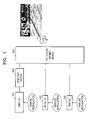
- FIG. 3 illustrates laser projection display according to an embodiment of the present invention.
- a blue LD 310 and a red LD 320 can directly adjust their outputs to 20 MHz so as to be suitable for pixel brightness using analog modulation without any problem.
- high-speed digital modulation controlling the number of pulses is used to adjust an output of a DBR-LD 301.
- the output light of the tunable DBR-LD 301 for green light generation is converted and digitally modulated to green light using a quasi-phase-matching second-harmonic generation (QPM-SHG) device 302.
- Green, blue, and red light sources are processed by a tri-color mixing device 330 and projected to a screen, whereby an image is displayed.
- QPM-SHG quasi-phase-matching second-harmonic generation
- FIG. 4 is a flowchart of a method of modulating a particular light source used for laser display according to an embodiment of the present invention.
- operation 401 light output from a semiconductor laser is digitally modulated to a frequency higher than a repetition frequency required to perform laser image display.
- operation 402 at least one high-speed pulse is inserted into a period of the modulated output light and the number of the inserted high-speed pulses is adjusted so as to control the brightness of a pixel.
- a green light source which is difficult to obtain using analog modulation, can be easily obtained from light output from a green semiconductor laser using digital modulation that is not sensitive to a change in wavelength.
- the brightness of a pixel can be distinctively realized using digital on/off modulation. As a result, improved laser display can be provided.
Landscapes
- Physics & Mathematics (AREA)
- Optics & Photonics (AREA)
- Engineering & Computer Science (AREA)
- Multimedia (AREA)
- Signal Processing (AREA)
- General Physics & Mathematics (AREA)
- Semiconductor Lasers (AREA)
- Projection Apparatus (AREA)
- Optical Modulation, Optical Deflection, Nonlinear Optics, Optical Demodulation, Optical Logic Elements (AREA)
- Control Of Indicators Other Than Cathode Ray Tubes (AREA)
Applications Claiming Priority (1)
| Application Number | Priority Date | Filing Date | Title |
|---|---|---|---|
| KR1020060109691A KR100819043B1 (ko) | 2006-11-07 | 2006-11-07 | 레이저 디스플레이 광원으로 사용되는 특정 광원의 변조장치 및 그 변조 방법 |
Publications (2)
| Publication Number | Publication Date |
|---|---|
| EP1921868A2 true EP1921868A2 (de) | 2008-05-14 |
| EP1921868A3 EP1921868A3 (de) | 2008-11-19 |
Family
ID=39030868
Family Applications (1)
| Application Number | Title | Priority Date | Filing Date |
|---|---|---|---|
| EP07120146A Ceased EP1921868A3 (de) | 2006-11-07 | 2007-11-07 | Verfahren und Vorrichtung zur Modulierung einer für eine Laseranzeige verwendeten bestimmten Lichtquelle |
Country Status (4)
| Country | Link |
|---|---|
| US (1) | US7810952B2 (de) |
| EP (1) | EP1921868A3 (de) |
| JP (1) | JP4856613B2 (de) |
| KR (1) | KR100819043B1 (de) |
Families Citing this family (2)
| Publication number | Priority date | Publication date | Assignee | Title |
|---|---|---|---|---|
| JP5609370B2 (ja) * | 2010-07-23 | 2014-10-22 | 船井電機株式会社 | 画像表示装置 |
| CN111505841B (zh) * | 2019-01-31 | 2023-06-23 | 成都理想境界科技有限公司 | 一种激光调制方法、激光扫描装置及系统 |
Citations (1)
| Publication number | Priority date | Publication date | Assignee | Title |
|---|---|---|---|---|
| JP2001189520A (ja) * | 1999-12-28 | 2001-07-10 | Sony Corp | 光源装置およびそれを用いた投射型表示装置 |
Family Cites Families (10)
| Publication number | Priority date | Publication date | Assignee | Title |
|---|---|---|---|---|
| JPS56153333A (en) | 1980-04-30 | 1981-11-27 | Fuji Photo Film Co Ltd | Laser recorder |
| JPH09115825A (ja) * | 1995-10-19 | 1997-05-02 | Nikon Corp | 走査型投影露光装置 |
| US5835650A (en) | 1995-11-16 | 1998-11-10 | Matsushita Electric Industrial Co., Ltd. | Optical apparatus and method for producing the same |
| JP2002043698A (ja) * | 1999-12-22 | 2002-02-08 | Yokogawa Electric Corp | Shgレーザ光源及びshgレーザ光源の変調方法 |
| US6671297B2 (en) | 2001-04-26 | 2003-12-30 | Matsushita Electric Industrial Co., Ltd. | Wavelength conversion device |
| JP4174195B2 (ja) * | 2001-05-28 | 2008-10-29 | キヤノン株式会社 | 画像表示装置 |
| JP2003295243A (ja) | 2002-04-04 | 2003-10-15 | Canon Inc | 高調波光源装置、その駆動方法、およびそれを用いた画像表示装置、画像形成装置、光記録装置 |
| JP3793208B2 (ja) * | 2004-03-23 | 2006-07-05 | キヤノン株式会社 | 変調光源、それを有する画像表示装置、および変調光源の駆動方式 |
| US7269193B2 (en) | 2004-06-28 | 2007-09-11 | Fuji Film Corp. | Semiconductor laser driving circuit and image recording apparatus |
| KR100621216B1 (ko) * | 2004-12-10 | 2006-09-13 | 한국전자통신연구원 | 아날로그/디지탈 혼합 방식 온도보상 기능을 구비한 광송신 장치 |
-
2006
- 2006-11-07 KR KR1020060109691A patent/KR100819043B1/ko not_active Expired - Fee Related
-
2007
- 2007-10-31 US US11/930,727 patent/US7810952B2/en not_active Expired - Fee Related
- 2007-11-07 EP EP07120146A patent/EP1921868A3/de not_active Ceased
- 2007-11-07 JP JP2007289979A patent/JP4856613B2/ja not_active Expired - Fee Related
Patent Citations (1)
| Publication number | Priority date | Publication date | Assignee | Title |
|---|---|---|---|---|
| JP2001189520A (ja) * | 1999-12-28 | 2001-07-10 | Sony Corp | 光源装置およびそれを用いた投射型表示装置 |
Also Published As
| Publication number | Publication date |
|---|---|
| US20080117492A1 (en) | 2008-05-22 |
| JP4856613B2 (ja) | 2012-01-18 |
| US7810952B2 (en) | 2010-10-12 |
| EP1921868A3 (de) | 2008-11-19 |
| JP2008116968A (ja) | 2008-05-22 |
| KR100819043B1 (ko) | 2008-04-02 |
Similar Documents
| Publication | Publication Date | Title |
|---|---|---|
| EP2271120B1 (de) | Lichtquellenvorrichtung, Videoprojektor und Videoprojektionsverfahren | |
| EP2169964B1 (de) | Projektionsvorrichtung und Projektionsverfahren | |
| US9462244B2 (en) | Image display apparatus and optical component | |
| KR101623996B1 (ko) | 휴대형 lcos/lcd/dlp 투사 시스템에서의 전력 소실 감소 | |
| US9542911B2 (en) | Display apparatus and method for controlling display apparatus | |
| US20050280850A1 (en) | Color signal processing apparatus and method | |
| EP2290443A1 (de) | Lichtquellenvorrichtung, Projektionsvorrichtung und Projektionsverfahren | |
| JP4546499B2 (ja) | 画像表示装置 | |
| JP2014021235A (ja) | プロジェクター、及び、プロジェクターにおける発光制御方法 | |
| US20070035723A1 (en) | Image display device and light source device | |
| US7810952B2 (en) | Method and apparatus for modulating particular light source used for laser display | |
| JP5407254B2 (ja) | 投影装置、投影方法及びプログラム | |
| JP2014063092A (ja) | 表示装置、プロジェクター及び表示装置の制御方法 | |
| JP2011203292A (ja) | 投射型表示装置 | |
| JP2014066805A (ja) | プロジェクター、及び、プロジェクターにおける発光制御方法 | |
| JP5445575B2 (ja) | 投影装置及び投影方法 | |
| JP5245944B2 (ja) | 投影装置、投影方法及びプログラム | |
| JP2009080277A (ja) | 投写型映像表示装置 | |
| JP2017010057A (ja) | プロジェクター、及び、プロジェクターにおける発光制御方法 | |
| US20110050662A1 (en) | Display | |
| JP2008026355A (ja) | 光源制御装置 | |
| KR100396677B1 (ko) | 레이저 시스템의 레이저 다이오드 광 모듈 장치 |
Legal Events
| Date | Code | Title | Description |
|---|---|---|---|
| PUAI | Public reference made under article 153(3) epc to a published international application that has entered the european phase |
Free format text: ORIGINAL CODE: 0009012 |
|
| AK | Designated contracting states |
Kind code of ref document: A2 Designated state(s): AT BE BG CH CY CZ DE DK EE ES FI FR GB GR HU IE IS IT LI LT LU LV MC MT NL PL PT RO SE SI SK TR |
|
| AX | Request for extension of the european patent |
Extension state: AL BA HR MK RS |
|
| PUAL | Search report despatched |
Free format text: ORIGINAL CODE: 0009013 |
|
| AK | Designated contracting states |
Kind code of ref document: A3 Designated state(s): AT BE BG CH CY CZ DE DK EE ES FI FR GB GR HU IE IS IT LI LT LU LV MC MT NL PL PT RO SE SI SK TR |
|
| AX | Request for extension of the european patent |
Extension state: AL BA HR MK RS |
|
| 17P | Request for examination filed |
Effective date: 20090519 |
|
| 17Q | First examination report despatched |
Effective date: 20090618 |
|
| AKX | Designation fees paid |
Designated state(s): AT BE BG CH CY CZ DE DK EE ES FI FR GB GR HU IE IS IT LI LT LU LV MC MT NL PL PT RO SE SI SK TR |
|
| STAA | Information on the status of an ep patent application or granted ep patent |
Free format text: STATUS: THE APPLICATION HAS BEEN REFUSED |
|
| 18R | Application refused |
Effective date: 20110111 |