EP1921775A1 - Schéma de sélection de station de base pour système cellulaire CDMA utilisant un canal sémaphore et SIR reçu - Google Patents
Schéma de sélection de station de base pour système cellulaire CDMA utilisant un canal sémaphore et SIR reçu Download PDFInfo
- Publication number
- EP1921775A1 EP1921775A1 EP08003676A EP08003676A EP1921775A1 EP 1921775 A1 EP1921775 A1 EP 1921775A1 EP 08003676 A EP08003676 A EP 08003676A EP 08003676 A EP08003676 A EP 08003676A EP 1921775 A1 EP1921775 A1 EP 1921775A1
- Authority
- EP
- European Patent Office
- Prior art keywords
- base station
- perch channel
- mobile station
- reception level
- measured
- Prior art date
- Legal status (The legal status is an assumption and is not a legal conclusion. Google has not performed a legal analysis and makes no representation as to the accuracy of the status listed.)
- Granted
Links
Images


Classifications
-
- H—ELECTRICITY
- H04—ELECTRIC COMMUNICATION TECHNIQUE
- H04W—WIRELESS COMMUNICATION NETWORKS
- H04W48/00—Access restriction; Network selection; Access point selection
- H04W48/20—Selecting an access point
-
- H—ELECTRICITY
- H04—ELECTRIC COMMUNICATION TECHNIQUE
- H04B—TRANSMISSION
- H04B7/00—Radio transmission systems, i.e. using radiation field
- H04B7/14—Relay systems
- H04B7/15—Active relay systems
- H04B7/155—Ground-based stations
-
- H—ELECTRICITY
- H04—ELECTRIC COMMUNICATION TECHNIQUE
- H04W—WIRELESS COMMUNICATION NETWORKS
- H04W36/00—Hand-off or reselection arrangements
- H04W36/24—Reselection being triggered by specific parameters
- H04W36/30—Reselection being triggered by specific parameters by measured or perceived connection quality data
-
- H—ELECTRICITY
- H04—ELECTRIC COMMUNICATION TECHNIQUE
- H04W—WIRELESS COMMUNICATION NETWORKS
- H04W48/00—Access restriction; Network selection; Access point selection
- H04W48/08—Access restriction or access information delivery, e.g. discovery data delivery
- H04W48/12—Access restriction or access information delivery, e.g. discovery data delivery using downlink control channel
-
- Y—GENERAL TAGGING OF NEW TECHNOLOGICAL DEVELOPMENTS; GENERAL TAGGING OF CROSS-SECTIONAL TECHNOLOGIES SPANNING OVER SEVERAL SECTIONS OF THE IPC; TECHNICAL SUBJECTS COVERED BY FORMER USPC CROSS-REFERENCE ART COLLECTIONS [XRACs] AND DIGESTS
- Y02—TECHNOLOGIES OR APPLICATIONS FOR MITIGATION OR ADAPTATION AGAINST CLIMATE CHANGE
- Y02D—CLIMATE CHANGE MITIGATION TECHNOLOGIES IN INFORMATION AND COMMUNICATION TECHNOLOGIES [ICT], I.E. INFORMATION AND COMMUNICATION TECHNOLOGIES AIMING AT THE REDUCTION OF THEIR OWN ENERGY USE
- Y02D30/00—Reducing energy consumption in communication networks
- Y02D30/70—Reducing energy consumption in communication networks in wireless communication networks
Definitions
- the present invention relates to a base station selection scheme for a CDMA (Code Division Multiple Access) cellular system, and more particularly, to a base station selection scheme in which a perch channel transmitted from each base station is received at a mobile station, and a base station is selected according to a reception level of the perch channel.
- CDMA Code Division Multiple Access
- a service area is formed by a plurality of small zones (cells), and these small zones are covered by a plurality of base stations, so that it is possible to achieve effects of a transmission power reduction and a subscriber capacity increase.
- the perch channel transmitted from each base station is received at the mobile station, and the closest base station is selected by comparing the perch channel reception levels for different base stations. In other words, the base station for which the perch channel reception level is the largest is judged as the closest base station.
- the perch channel reception levels measured at the mobile station are reported to the closest base station or the base station currently in communication with the mobile station, and the base station selection is carried out at the closest base station or the base station currently in communication with the mobile station according to the reported perch channel reception levels.
- one radio access scheme that can be used in the cellular system is a CDMA scheme, and a use of the base station selection based on the perch channel reception level measurement in the CDMA is currently contemplated.
- the identical frequency is commonly used by a plurality of users, so that the signals of the other user cause the interference, and the receiving quality is determined by a ratio of the reception level and the interference level (SIR: Signal to Interference Ratio). Consequently, the transmission power control is indispensable in the CDMA, and the transmission power control based on the received SIR has been proposed in order to maintain a constant receiving quality (see, T. Dohi, et al: "Performance of SIR Based Power Control in the Presence of Non-uniform Traffic Distribution", 1995 Fourth IEEE International Conference on Universal Personal Communications Record, pp. 334-338, November 1995 ).
- the base station for which the perch channel reception level at that base station is the largest will be selected by assuming that the uplink and downlink propagation losses are equal, but the interference levels are different for different base stations, so that the transmission power of the mobile station may not necessarily becomes smallest when the mobile station is connected with the base station selected in this manner.
- the base station selection according to the conventional base station selection scheme may lead to an increase of the transmission power and a degradation of the subscriber capacity.
- a method of base station selection in a CDMA cellular system formed by a plurality of base stations connected with a communication network and at least one mobile station, comprising the steps of: measuring an uplink interference level at each base station; transmitting a perch channel from each base station to the mobile station; measuring a perch channel reception level of the perch channel transmitted from each base station at the mobile station; and selecting a connection target base station to be connected with the mobile station according to a received SIR (Signal to Interference Ratio) of each base station determined from the perch channel reception level measured at the mobile station and the uplink interference level measured at each base station.
- SIR Signal to Interference Ratio
- a CDMA cellular system with a base station selection function comprising: a plurality of base stations connected with a communication network, each base station including: a device for measuring an uplink interference level at each base station; and a device for transmitting a perch channel from each base station; at least one mobile station, including: a device for measuring a perch channel reception level of the perch channel transmitted from each base station; and means for selecting a connection target base station to be connected with the mobile station according to a received SIR of each base station determined from the perch channel reception level measured at the mobile station and the uplink interference level measured at each base station.
- a base station selection scheme for a CDMA cellular system according to the present invention will be described in detail.
- Fig. 1 shows an exemplary configuration of a CDMA cellular system to which the base station selection scheme of this embodiment is applied.
- base stations 1 to 3 connected with a communication network 5 are transmitting perch channels PERCH1 to PERCH3 and broadcast control channels BCCH1 to BCCH3, respectively.
- a mobile station 4 measures reception levels of the perch channels transmitted from the base stations 1 to 3, and selects a connection target base station according to the measured reception levels.
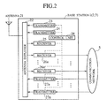
- Each of the base station 1 to 3 has a configuration as shown in Fig. 2 , which comprises an antenna 21 for transmitting and receiving radio signals to and from the mobile stations, an antenna duplexer 22 for enabling a use of the antenna 21 for both signal transmission and reception, a plurality of transmitters 23, 24 and 27a to 27n, a plurality of receivers 25 and 26a to 26n, and a control unit 28 for carrying out a control of each element of this base station, various data processing, and a control of signal transmission and reception for the purpose of communications with the mobile stations.
- the transmitter 23 is used for transmitting the perch channel, while the transmitter 24 is used for transmitting the broadcast control channel. Note here that the perch channel and the broadcast control channel are separately provided in this embodiment, but it is also possible to provide them commonly.
- the receiver 25 is used for measuring an uplink interference level, while the receivers 26a to 26n and the transmitters 27a to 27n are used for communications with the mobile stations. Signals received from the mobile stations by the receivers 26a to 26n are sent to the communication network 5, while signals sent from the communication network 5 are transmitted to the mobile stations by the transmitters 27a to 27n.
- the control unit 28 produces an interference level information according to the interference level measured by the receiver 25, and controls the transmitter 24 to transmit the interference level information through the broadcast control channel.
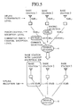
- the mobile station 4 has a configuration as shown in Fig. 3 , which comprises an antenna 31 for transmitting and receiving radio signals to and from the base stations, an antenna duplexer 32 for enabling a use of the antenna 31 for both signal transmission and reception, receivers 33 and 34, a transmitter 35, a control unit 36 for carrying out a control of each element of this mobile station and various data processing, a baseband processing unit 37, and a handset 38.
- the receiver 33 is used for measuring reception levels of the perch channels transmitted by the base stations, and for receiving the broadcast control channels transmitted by the base stations.
- the receiver 34 receives speech data from the base stations, and the received speech data are converted into speech signals by the baseband processing unit 37 and sent to the handset 38. Also, the speech signals sent from the handset 38 are converted into speech data by the baseband processing unit 37 and transmitted to the base stations by the transmitter 35.
- the control unit carries out the base station selection according to the perch channel reception levels measured by the receiver 33 and the interference level information received through the broadcast control channels, while controlling the transmitters 35, the receivers 33 and 34, the baseband processing unit 37 and the handset 38 for the purpose of communication with the base stations.
- the uplink interference level measured by the receiver 25 of the base station is converted into the interference level information by the control unit 28 of the base station according to a conversion table shown in Fig. 4 , and the converted interference level information is transmitted by the transmitter 24.
- the interference level information transmitted from the base stations 1 to 3 are "00110010" through BCCH1, "01000110" through BCCH2, and "00111100” through BCCH3.
- the mobile station 4 receives these interference level information, corrects the measured perch channel reception levels according to these interference level information, and selects the connection target base station according to the corrected perch channel reception levels. For example, suppose that the perch channel reception level for PERCH1 is 50 dB ⁇ , the perch channel reception level for PERCH2 is 60.dB ⁇ , and the perch channel reception level for PERCH3 is 30 dB ⁇ , as indicated in Fig. 5 . In this case, if the base station selection is made without the level correction, the base station 2 that has the largest perch channel reception level would be selected.
- the received SIR at the base station 1 is ( ⁇ +50-30) dB
- the received SIR at the base station 2 is ( ⁇ +60-50) dB
- the received SIR at the base station 3 is ( ⁇ +30-40) dB
- ⁇ is an offset determined by the transmission power of the mobile station 4, so that the received SIR is actually the largest for the base station 1.
- the transmission power of the mobile station 4 can be made smaller by connecting the mobile station 4 with the base station 1 rather than the base station2, but this optimal base station selection cannot be realized by the base station selection without the level correction.
- the corrected reception level of PERCH1 becomes 20 dB ⁇
- the corrected reception level of PERCH2 becomes 10 dB ⁇
- the corrected reception level of PERCH3 becomes -10 dB ⁇
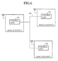
- each base station obtains the information level information of its surrounding base stations through the control unit 28 which is connected with the control units 28 of the surrounding base stations by a wire or radio control link 40 as shown in Fig. 6 , and transmits the interference level information of this base station as well as the interference level information of its surrounding base stations through the broadcast control channel. Consequently, the mobile station 4 can obtain the interference level information of its surrounding base stations by simply receiving the broadcast control channel of the nearest base station alone.
- the base station 1 transmits the broadcast control information as shown in Fig. 7 , which indicates the interference level information of each base station in correspondence to a base station ID of each base station, for this base station 1 as well as for its surrounding base stations 2 and 3.
- the mobile station 4 can select the optimal base station without using the interference level information.
- the control unit 28 of the base station specifies the perch channel transmission power to be used by the transmitter 23 in correspondence to the uplink interference level measurement result, according to a correspondence table shown in Fig. 8 which is stored in a table form at a memory within the control unit 28.
- each base station reduces the perch channel transmission power as much as the uplink interference level at each base station, so that the perch channel reception levels measured at the mobile station 4 reflect the interference levels at the base stations.
- the level correction for the perch channel reception level is carried out at the base station side.
- the perch channel reception level measured by the receiver 33 is converted into a corresponding perch channel reception level information by the control unit 36, according to a conversion table shown in Fig. 9 which is stored in a memory (not shown) provided within the mobile station 4, and the converted perch channel reception level information is transmitted as a control signal to one base station by the transmitter 35.
- this one base station is chosen by the mobile station 4 according to the measured perch channel reception levels, as a base station for which the measured perch channel reception level is largest.
- the mobile station 4 reports to the base station 2 the perch channel reception level report information as shown in Fig. 10 , which indicates the perch channel reception level information of each base station in correspondence to a base station ID of each base station, for this base station 2 as well as for its surrounding base stations 1 and 3.
- the level correction for the perch channel reception levels reported from the mobile station 4 is carried out according to the uplink interference level (50 dB ⁇ ) measured at this base station 2 as well as the uplink interference level (30 dB ⁇ ) of the base station 1 and the uplink interference level (40 dB ⁇ ) of the base station 3 which are obtained through the control unit 28 in a manner similar to that indicated in Fig. 6 described above, and the base station to be connected with the mobile station 4 is selected. More specifically, the level correction is carried out in this fourth scheme as follows.
- the corrected reception level of PERCH1 becomes 20 dB ⁇
- the corrected reception level of PERCH2 becomes 10 dB ⁇
- the corrected reception level of PERCH3 becomes -10 dB ⁇
- the mobile station corrects the perch channel reception level of each base station according to the uplink interference level information of each base station, and selects the base station according to the corrected perch channel reception levels, so that it is possible to select the optimal base station which can minimize the mobile station transmission power. Consequently, it is possible to reduce the power consumption and realize a longer communication possible period and/or a reduced size of the mobile station, while reducing the interference and increasing the subscriber capacity in the system.
- each base station obtains the uplink interference levels of the surrounding base stations and transmits the interference level information for this base station as well as for the surrounding base stations through the broadcast control channel, while the mobile station corrects the perch channel reception level of each base station according to the received interference level information and selects the base station according to the corrected perch channel reception levels, so that it is also possible to select the optimal base station which can minimize the mobile station transmission power. Consequently, it is possible to reduce the power consumption and realize a longer communication possible period and/or a reduced size of the mobile station, while reducing the interference and increasing the subscriber capacity in the system. In addition, it is sufficient for the mobile station to receive the broadcast control information from one base station alone, so that it is also possible to reduce the processing at the mobile station.
- each base station measures the uplink interference level and changes the perch channel transmission power according to the measured interference level, and the mobile station selects the base station according to the perch channel reception levels resulting from the changed perch channel transmission powers, so that it is also possible to select the optimal base station which can minimize the mobile station transmission power. Consequently, it is possible to reduce the power consumption and realize a longer communication possible period and/or a reduced size of the mobile station, while reducing the interference and increasing the subscriber capacity in the system.
- each base station transmits the interference level information through the broadcast control channel, and there is no need for the mobile station to carry out the level correction processing according to the interference levels, so that it is also possible to reduce the processing at the mobile station and the base station.
- each base station measures the uplink interference level and obtains the uplink interference levels of the surrounding base stations, corrects the perch channel reception levels reported from the mobile station according to the interference levels, and selects the base station according to the corrected perch channel reception levels, so that it is also possible to select the optimal base station which can minimize the mobile station transmission power. Consequently, it is possible to reduce the power consumption and realize a longer communication possible period and/or a reduced size of the mobile station, while reducing the interference and increasing the subscriber capacity in the system. In addition, there is no need for each base station to change the perch channel transmission power and to transmit the interference level information through the broadcast control channel, so that it is also possible to reduce the processing at the base station.
- the base station to be connected with the mobile station is selected according to the received SIR of each base station by accounting for the uplink interference level at each base station, so that it is also possible to select the optimal base station which can minimize the mobile station transmission power. Consequently, it is possible to reduce the power consumption and realize a longer communication possible period and/or a reduced size of the mobile station, while reducing the interference and increasing the subscriber capacity in the system.
- connection target base station selection the selection of the connection target base station is to be carried out at the mobile station, but it is also possible to modify the present invention in such a manner that the mobile station only selects candidate connection target base stations according to the scheme of the present invention as described above and then notifies the selected candidate connection target base stations to the base stations so that the final connection target base station selection can be made at the base station side.
- This modification can be used for a case of setting up a radio channel between the base station and the mobile station at a beginning of a communication where the final selection of the connection target base station also depends on the available idle communication channels which are managed at the base station side.
- connection target base station should be carried out at the base station side, as should be apparent from the above description.
- Example 1 describes a method of base station selection in a CDMA cellular system formed by a plurality of base stations connected with a communication network and at least one mobile station, comprising the steps of: measuring an uplink interference level at each base station; transmitting a perch channel from each base station to the mobile station; measuring a perch channel reception level of the perch channel transmitted from each base station at the mobile station; and selecting a connection target base station to be connected with the mobile station according to a received SIR (Signal to Interference Ratio) of each base station determined from the perch channel reception level measured at the mobile station and the uplink interference level measured at each base station.
- SIR Signal to Interference Ratio
- Example 2 describes the method of example 1, further comprising the steps of: transmitting a broadcast control channel indicating the uplink interference level measured at each base station, from each base station to the mobile station; and correcting the perch channel reception level for each base station measured at the mobile station according to the uplink interference level indicated by the broadcast control channel received from each base station, to obtain a corrected perch channel reception level for each base station; wherein the selecting step selects the connection target base station according to the received SIR of each base station indicated by the corrected perch channel reception level for each base station.
- Example 3 describes the method of example 2, wherein the correcting step is carried out at the mobile station.
- Example 4 describes the method of example 1, further comprising the steps of: obtaining at one base station the uplink interference levels measured by surrounding base stations; transmitting a broadcast control channel indicating the uplink interference levels of said one base station and the surrounding base stations, from said one base station to the mobile station; and correcting the perch channel reception level for each base station measured at the mobile station according to the uplink interference level indicated by the broadcast control channel received from said one base station, to obtain a corrected perch channel reception level for each base station; wherein the selecting step selects the connection target base station according to the received SIR of each base station indicated by the corrected perch channel reception level for each base station.
- Example 5 describes the method of example 4, wherein the correcting step is carried out at the mobile station.
- Example 6 describes the method of example 1, further comprising the step of: changing a perch channel transmission power of the perch channel transmitted by each base station according to the uplink interference level measured by each base station; wherein the selecting step selects the connection target base station according to the received SIR of each base station indicated by the perch channel reception level for each base station measured by the mobile station which reflects the uplink interference level measured by each base station.
- Example 7 describes the method of example 1, further comprising the steps of: reporting the perch channel reception level for each base station measured by the mobile station, from the mobile station to one base station; obtaining at said one base station the uplink interference levels measured by surrounding base stations; correcting the perch channel reception level for each base station reported from the mobile station according to the uplink interference levels of said one base station and the surrounding base stations, to obtain a corrected perch channel reception level for each base station; wherein the selecting step selects the connection target base station according to the received SIR of each base station indicated by the corrected perch channel reception level for each base station.
- Example 8 describes the method of example 7, wherein the correcting step is carried out by said one base station.
- Example 9 describes the method of example 7, wherein said one base station is one of said plurality of base stations which is chosen by the mobile station according to the perch channel reception level for each base station measured by the mobile station.
- Example 10 describes the method of example 7, wherein said one base station is one of said plurality of base stations for which the perch channel reception level measured by the mobile station is largest.
- Example 11 describes a CDMA cellular system with a base station selection function, comprising: a plurality of base stations connected with a communication network, each base station including: a device for measuring an uplink interference level at each base station; and a device for transmitting a perch channel from each base station; at least one mobile station, including: a device for measuring a perch channel reception level of the perch channel transmitted from each base station; and means for selecting a connection target base station to be connected with the mobile station according to a received SIR of each base station determined from the perch channel reception level measured at the mobile station and the uplink interference level measured at each base station.
- Example 12 describes the system of example 11, further comprising: a device included in each base station for transmitting a broadcast control channel indicating the uplink interference level measured at each base station, from each base station to the mobile station; and means for correcting the perch channel reception level for each base station measured at the mobile station according to the uplink interference level indicated by the broadcast control channel received from each base station, to obtain a corrected perch channel reception level for each base station; wherein the selecting means selects the connection target base station according to the received SIR of each base station indicated by the corrected perch channel reception level for each base station.
- Example 13 describes the system of example 12, wherein the correcting means is provided at the mobile station.
- Example 14 describes the system of example 11, further comprising: means for obtaining at one base station the uplink interference levels measured by surrounding base stations; a device included in said one base station for transmitting a broadcast control channel indicating the uplink interference levels of said one base station and the surrounding base stations, from said one base station to the mobile station; and means for correcting the perch channel reception level for each base station measured at the mobile station according to the uplink interference level indicated by the broadcast control channel received from said one base station, to obtain a corrected perch channel reception level for each base station; wherein the selecting means selects the connection target base station according to the received SIR of each base station indicated by the corrected perch channel reception level for each base station.
- Example 15 describes the system of example 14, wherein the correcting means is provided at the mobile station.
- Example 16 describes the system of example 11, further comprising: a device included in each base station for changing a perch channel transmission power of the perch channel transmitted by each base station according to the uplink interference level measured by each base station; wherein the selecting means selects the connection target base station according to the received SIR of each base station indicated by the perch channel reception level for each base station measured by the mobile station which reflects the uplink interference level measured by each base station.
- Example 17 describes the system of example 11, further comprising: a device included in the mobile station for reporting the perch channel reception level for each base station measured by the mobile station, from the mobile station to one base station; means for obtaining at said one base station the uplink interference levels measured by surrounding base stations; means for correcting the perch channel reception level for each base station reported from the mobile station according to the uplink interference levels of said one base station and the surrounding base stations, to obtain a corrected perch channel reception level for each base station; wherein the selecting means selects the connection target base station according to the received SIR of each base station indicated by the corrected perch channel reception level for each base station.
- Example 18 describes the system of example 17, wherein the correcting means is provided at said one base station.
- Example 19 describes the system of example 17, wherein said one base station is one of said plurality of base stations which is chosen by the mobile station according to the perch channel reception level for each base station measured by the mobile station.
- Example 20 describes the system of example 17, wherein said one base station is one of said plurality of base stations for which the perch channel reception level measured by the mobile station is largest.
Landscapes
- Engineering & Computer Science (AREA)
- Computer Networks & Wireless Communication (AREA)
- Signal Processing (AREA)
- Computer Security & Cryptography (AREA)
- Mobile Radio Communication Systems (AREA)
Applications Claiming Priority (3)
| Application Number | Priority Date | Filing Date | Title |
|---|---|---|---|
| JP32476895 | 1995-12-13 | ||
| JP08007792A JP3078216B2 (ja) | 1995-12-13 | 1996-01-19 | 基地局選択方法 |
| EP96120068A EP0779755B1 (fr) | 1995-12-13 | 1996-12-13 | Sélection de station de base d'un système cellulaire CDMA utilisant un canal sémaphore et l'interférence reçue |
Related Parent Applications (2)
| Application Number | Title | Priority Date | Filing Date |
|---|---|---|---|
| EP96120068A Division EP0779755B1 (fr) | 1995-12-13 | 1996-12-13 | Sélection de station de base d'un système cellulaire CDMA utilisant un canal sémaphore et l'interférence reçue |
| EP96120068.0 Division | 1996-12-13 |
Publications (2)
| Publication Number | Publication Date |
|---|---|
| EP1921775A1 true EP1921775A1 (fr) | 2008-05-14 |
| EP1921775B1 EP1921775B1 (fr) | 2010-09-01 |
Family
ID=26342161
Family Applications (2)
| Application Number | Title | Priority Date | Filing Date |
|---|---|---|---|
| EP08003676A Expired - Lifetime EP1921775B1 (fr) | 1995-12-13 | 1996-12-13 | Schéma de sélection de station de base pour système cellulaire CDMA utilisant un canal sémaphore |
| EP96120068A Expired - Lifetime EP0779755B1 (fr) | 1995-12-13 | 1996-12-13 | Sélection de station de base d'un système cellulaire CDMA utilisant un canal sémaphore et l'interférence reçue |
Family Applications After (1)
| Application Number | Title | Priority Date | Filing Date |
|---|---|---|---|
| EP96120068A Expired - Lifetime EP0779755B1 (fr) | 1995-12-13 | 1996-12-13 | Sélection de station de base d'un système cellulaire CDMA utilisant un canal sémaphore et l'interférence reçue |
Country Status (7)
| Country | Link |
|---|---|
| US (1) | US5832368A (fr) |
| EP (2) | EP1921775B1 (fr) |
| JP (1) | JP3078216B2 (fr) |
| KR (1) | KR100209771B1 (fr) |
| CN (1) | CN1079183C (fr) |
| CA (1) | CA2192925C (fr) |
| DE (2) | DE69638253D1 (fr) |
Families Citing this family (67)
| Publication number | Priority date | Publication date | Assignee | Title |
|---|---|---|---|---|
| JP2872621B2 (ja) * | 1995-08-29 | 1999-03-17 | 株式会社ケンウッド | デジタル移動電話機のローミング制御方式 |
| JP3361694B2 (ja) * | 1996-06-07 | 2003-01-07 | 株式会社エヌ・ティ・ティ・ドコモ | Cdma移動通信システムにおけるパイロットチャネル送信およびセル選択方法、移動局 |
| EP0813317B1 (fr) * | 1996-06-14 | 2006-10-25 | NTT DoCoMo, Inc. | Méthode et appareil de transmission de signaux CDMA dans un système de communication mobile |
| US6493561B1 (en) | 1996-06-24 | 2002-12-10 | Fujitsu Limited | Mobile communication system enabling efficient use of small-zone base stations |
| DE69731378T2 (de) * | 1996-12-27 | 2005-10-20 | Ntt Docomo Inc. | Anrufannahmesteuerungsverfahren für ein cdma-mobilfunksystem und mobilstation |
| EP0856955A3 (fr) | 1997-01-29 | 2000-09-06 | YRP Mobile Telecommunications Key Technology Research Laboratories Co., Ltd. | Régulation de puissance dans un système AMDC |
| CN1494236A (zh) * | 1997-04-24 | 2004-05-05 | ��ʽ����Ntt����Ħ | 移动通信方法和移动通信系统 |
| JP3028940B2 (ja) * | 1997-09-02 | 2000-04-04 | 日本電気株式会社 | 通信チャネル割り当て方式 |
| US6144650A (en) * | 1997-09-25 | 2000-11-07 | Matsushita Electric Industrial Co., Ltd. | Mobile communication system |
| CA2248487C (fr) * | 1997-10-31 | 2002-01-15 | Lucent Technologies Inc. | Regulation de puissance pour systeme de communication mobile sans fil |
| US9118387B2 (en) | 1997-11-03 | 2015-08-25 | Qualcomm Incorporated | Pilot reference transmission for a wireless communication system |
| US6574211B2 (en) * | 1997-11-03 | 2003-06-03 | Qualcomm Incorporated | Method and apparatus for high rate packet data transmission |
| US7184426B2 (en) | 2002-12-12 | 2007-02-27 | Qualcomm, Incorporated | Method and apparatus for burst pilot for a time division multiplex system |
| US5963865A (en) * | 1997-11-24 | 1999-10-05 | Telefonaktiebolaget Lm Ericsson | Traffic channel assignment in a cellular telephone system using an uplink interference driven frequency packing method |
| KR100244198B1 (ko) | 1997-12-09 | 2000-02-01 | 윤종용 | 기지국 환경 잡음 측정기 및 측정방법 |
| KR20000007433A (ko) * | 1998-07-03 | 2000-02-07 | 윤종용 | 주파수 도약 시스템에서의 이동무선결합기의 프리 퍼런스 구현방법 |
| US6519245B1 (en) * | 1999-01-11 | 2003-02-11 | Trimble Navigation Limited | Communication system having dedicated time slots for selection signals |
| KR100282959B1 (ko) * | 1999-01-23 | 2001-02-15 | 윤종용 | 선택적 이중경로 수신기를 이용한 기지국 |
| EP1039658B1 (fr) * | 1999-02-26 | 2007-11-07 | Texas Instruments Incorporated | Procédé pour faire fonctionner un circuit de communication |
| US6424643B1 (en) * | 1999-03-08 | 2002-07-23 | Scoreboard, Inc. | Method of modeling a CDMA cellular telephone system |
| GB9906005D0 (en) * | 1999-03-17 | 1999-05-12 | Motorola Ltd | A subscriber unit and method of cell selection for a cellular communication system |
| US6456606B1 (en) | 1999-03-24 | 2002-09-24 | Qualcomm Incorporated | Handoff control in an asynchronous CDMA system |
| US6556549B1 (en) | 1999-07-02 | 2003-04-29 | Qualcomm Incorporated | Method and apparatus for signal combining in a high data rate communication system |
| EP1067816A1 (fr) * | 1999-07-09 | 2001-01-10 | Alcatel | Station de base pour pour réseau de radiocommunications AMRC et terminal radio pour communiquer avec ledit réseau |
| JP3690717B2 (ja) * | 1999-07-14 | 2005-08-31 | 株式会社エヌ・ティ・ティ・ドコモ | セルサーチ制御方法、移動局および移動通信システム |
| MXPA02001782A (es) * | 1999-08-23 | 2002-08-12 | Ericsson Inc | Metodo de reseleccion de canal sin costura para conmutar de un canal en una celda a un segundo canal en otra celda para servicios de datos moviles. |
| US8064409B1 (en) | 1999-08-25 | 2011-11-22 | Qualcomm Incorporated | Method and apparatus using a multi-carrier forward link in a wireless communication system |
| US6621804B1 (en) | 1999-10-07 | 2003-09-16 | Qualcomm Incorporated | Method and apparatus for predicting favored supplemental channel transmission slots using transmission power measurements of a fundamental channel |
| US6603753B1 (en) * | 1999-12-03 | 2003-08-05 | Lucent Technologies Inc. | Down-link transmission inter-cell scheduling in CDMA data networks |
| US6577875B1 (en) | 2000-04-18 | 2003-06-10 | Telefonaktiebolaget Lm Ericsson (Publ) | Cellular communications system/method with uplink interference ceiling |
| US6684061B1 (en) * | 2000-07-20 | 2004-01-27 | Telefonaktiebolaget Lm Ericsson (Publ) | Systems and methods for measuring interference reciprocity between uplink and downlink directions in a wireless communications system |
| KR100430597B1 (ko) * | 2000-09-29 | 2004-05-10 | 가부시키가이샤 엔.티.티.도코모 | 셀 제어 방법 및 셀 시스템 |
| CN1159931C (zh) * | 2000-10-02 | 2004-07-28 | 株式会社Ntt都科摩 | 移动通信系统、基站移动站和移动通信控制方法 |
| US7154846B2 (en) * | 2000-10-24 | 2006-12-26 | Nortel Networks Limited | Shared channel structure, ARQ systems and methods |
| US6973098B1 (en) | 2000-10-25 | 2005-12-06 | Qualcomm, Incorporated | Method and apparatus for determining a data rate in a high rate packet data wireless communications system |
| US7068683B1 (en) | 2000-10-25 | 2006-06-27 | Qualcomm, Incorporated | Method and apparatus for high rate packet data and low delay data transmissions |
| US6801767B1 (en) * | 2001-01-26 | 2004-10-05 | Lgc Wireless, Inc. | Method and system for distributing multiband wireless communications signals |
| GB0104610D0 (en) * | 2001-02-23 | 2001-04-11 | Koninkl Philips Electronics Nv | Radio communication system |
| US6587697B2 (en) | 2001-05-14 | 2003-07-01 | Interdigital Technology Corporation | Common control channel uplink power control for adaptive modulation and coding techniques |
| SE524688C2 (sv) * | 2001-12-06 | 2004-09-14 | Ericsson Telefon Ab L M | Metod och anordningar för att allokera kanal till en mobilstation i ett radiokommunikationssystem |
| GB2391755B (en) * | 2002-08-10 | 2006-01-11 | Motorola Inc | Apparatus and method for cell selection in cellular communcation system |
| US8213390B2 (en) | 2002-10-24 | 2012-07-03 | Qualcomm Incorporated | Reverse link automatic repeat request |
| US7564818B2 (en) | 2002-11-26 | 2009-07-21 | Qualcomm Incorporated | Reverse link automatic repeat request |
| JP2005012429A (ja) * | 2003-06-18 | 2005-01-13 | Matsushita Electric Ind Co Ltd | 移動通信端末及びハンドオーバ制御方法 |
| US7480486B1 (en) * | 2003-09-10 | 2009-01-20 | Sprint Spectrum L.P. | Wireless repeater and method for managing air interface communications |
| US7406295B1 (en) | 2003-09-10 | 2008-07-29 | Sprint Spectrum L.P. | Method for dynamically directing a wireless repeater |
| WO2006049177A1 (fr) * | 2004-11-02 | 2006-05-11 | Matsushita Electric Industrial Co., Ltd. | Dispositif de station mobile et procede de selection de partenaire de communication |
| US9955438B2 (en) | 2005-09-27 | 2018-04-24 | Qualcomm Incorporated | Method and apparatus for carrier allocation and management in multi-carrier communication systems |
| JP4555220B2 (ja) * | 2005-12-26 | 2010-09-29 | 株式会社日立製作所 | ハンドオーバの制御方法および基地局制御装置 |
| JP4912739B2 (ja) | 2006-05-16 | 2012-04-11 | 株式会社トプコン | Rtk−gps測量システム |
| CN101518114B (zh) * | 2006-09-20 | 2012-03-21 | 日本电气株式会社 | 蜂窝系统的载波分配方法、蜂窝系统、基站以及移动台站 |
| JP2008098847A (ja) * | 2006-10-10 | 2008-04-24 | Nec Corp | 移動通信システムおよびハンドオーバ制御方法 |
| JP4755259B2 (ja) * | 2006-12-26 | 2011-08-24 | 富士通株式会社 | 通信装置および通信方法 |
| US8891489B2 (en) * | 2007-03-19 | 2014-11-18 | Qualcomm Incorporated | Handover mechanism that exploits uplink channel quality of a target cell |
| US8200228B2 (en) * | 2007-06-15 | 2012-06-12 | Telefonaktiebolaget Lm Ericsson (Publ) | Reading neighboring cell system information |
| US20090022178A1 (en) * | 2007-07-16 | 2009-01-22 | Qualcomm Incorporated | Methods and systems for adaptive transmission of control information in a wireless communication system |
| JP5156498B2 (ja) * | 2008-06-18 | 2013-03-06 | 株式会社エヌ・ティ・ティ・ドコモ | 基地局及び移動通信方法 |
| US8379551B2 (en) * | 2009-08-18 | 2013-02-19 | Qualcomm Incorporated | Radio selection in a multi-radio device |
| US8811200B2 (en) | 2009-09-22 | 2014-08-19 | Qualcomm Incorporated | Physical layer metrics to support adaptive station-dependent channel state information feedback rate in multi-user communication systems |
| JP5229398B2 (ja) * | 2009-10-30 | 2013-07-03 | 富士通株式会社 | 基地局、通信方法および移動局 |
| US8762543B2 (en) * | 2009-12-15 | 2014-06-24 | Intel Corporation | Method and apparatus for autonomous peer discovery and enhancing link reliability for wireless peer direct links |
| EP2566266B1 (fr) * | 2010-04-27 | 2018-07-11 | Fujitsu Limited | Procédé de communication sans fil, station de base sans fil, terminal mobile et système de communication sans fil |
| US8958319B2 (en) * | 2011-04-29 | 2015-02-17 | Telefonaktiebolaget L M Ericsson (Publ) | Decentralized control of interference reduction in a wireless communication system |
| JP6007743B2 (ja) * | 2012-11-16 | 2016-10-12 | 富士通株式会社 | マルチホップ通信端末、マルチホップ通信システム、及びマルチホップ通信方法 |
| JP2013176121A (ja) * | 2013-04-15 | 2013-09-05 | Mitsubishi Electric Corp | 通信方法、移動局及び基地局 |
| US9730135B1 (en) * | 2016-07-28 | 2017-08-08 | At&T Intellectual Property I, L.P. | Radio access network resource configuration for groups of mobile devices |
| US10547526B2 (en) | 2018-05-17 | 2020-01-28 | At&T Intellectual Property I, L.P. | Systems and methods for network analysis and management |
Citations (3)
| Publication number | Priority date | Publication date | Assignee | Title |
|---|---|---|---|---|
| US4435840A (en) | 1981-06-22 | 1984-03-06 | Nippon Electric Co., Ltd. | Radio mobile communication system wherein probability of loss of calls is reduced without a surplus of base station equipment |
| WO1995024810A1 (fr) | 1994-03-07 | 1995-09-14 | Ericsson Inc. | Procede et systeme pour l'affectation de canaux, utilisant la commande de la puissance et des mesures effectuees depuis les postes mobiles, par commutations |
| EP0680160A2 (fr) | 1994-04-27 | 1995-11-02 | Ntt Mobile Communications Network Inc. | Procédé et dispositif de contrôle de la puissance de transmission d'une station mobile pendant une commutation douce dans un système à accès multiple par division de code |
Family Cites Families (7)
| Publication number | Priority date | Publication date | Assignee | Title |
|---|---|---|---|---|
| US4549311A (en) * | 1982-08-03 | 1985-10-22 | Motorola, Inc. | Method and apparatus for measuring the strength of a radio signal frequency |
| JP2854346B2 (ja) * | 1989-09-19 | 1999-02-03 | 日本電信電話株式会社 | チャネル割当方法 |
| US5038399A (en) * | 1990-05-21 | 1991-08-06 | Motorola, Inc. | Method for assigning channel reuse levels in a multi-level cellular system |
| GB2268371B (en) * | 1992-04-10 | 1995-09-20 | Roke Manor Research | Radio communication systems |
| JP2795072B2 (ja) * | 1992-07-09 | 1998-09-10 | 日本電気株式会社 | 移動通信システムのチャネル割当方法 |
| SE9202367L (sv) * | 1992-08-18 | 1993-07-26 | Televerket | Foerfarande foer uppskattning av c/i-densitet och interferenssannolikhet i upplaenk |
| FI95187C (fi) * | 1992-11-30 | 1995-12-27 | Nokia Telecommunications Oy | Menetelmä viereisten tukiasemien mittaamiseksi TDMA-radiojärjestelmässä sekä TDMA-radiojärjestelmä |
-
1996
- 1996-01-19 JP JP08007792A patent/JP3078216B2/ja not_active Expired - Lifetime
- 1996-12-12 US US08/766,470 patent/US5832368A/en not_active Expired - Lifetime
- 1996-12-13 KR KR1019960065072A patent/KR100209771B1/ko not_active IP Right Cessation
- 1996-12-13 DE DE69638253T patent/DE69638253D1/de not_active Expired - Lifetime
- 1996-12-13 EP EP08003676A patent/EP1921775B1/fr not_active Expired - Lifetime
- 1996-12-13 CN CN96121548A patent/CN1079183C/zh not_active Expired - Fee Related
- 1996-12-13 DE DE69638215T patent/DE69638215D1/de not_active Expired - Lifetime
- 1996-12-13 CA CA002192925A patent/CA2192925C/fr not_active Expired - Fee Related
- 1996-12-13 EP EP96120068A patent/EP0779755B1/fr not_active Expired - Lifetime
Patent Citations (3)
| Publication number | Priority date | Publication date | Assignee | Title |
|---|---|---|---|---|
| US4435840A (en) | 1981-06-22 | 1984-03-06 | Nippon Electric Co., Ltd. | Radio mobile communication system wherein probability of loss of calls is reduced without a surplus of base station equipment |
| WO1995024810A1 (fr) | 1994-03-07 | 1995-09-14 | Ericsson Inc. | Procede et systeme pour l'affectation de canaux, utilisant la commande de la puissance et des mesures effectuees depuis les postes mobiles, par commutations |
| EP0680160A2 (fr) | 1994-04-27 | 1995-11-02 | Ntt Mobile Communications Network Inc. | Procédé et dispositif de contrôle de la puissance de transmission d'une station mobile pendant une commutation douce dans un système à accès multiple par division de code |
Also Published As
| Publication number | Publication date |
|---|---|
| CN1079183C (zh) | 2002-02-13 |
| EP1921775B1 (fr) | 2010-09-01 |
| CA2192925C (fr) | 2000-06-13 |
| JP3078216B2 (ja) | 2000-08-21 |
| EP0779755A2 (fr) | 1997-06-18 |
| CN1155822A (zh) | 1997-07-30 |
| KR970055862A (ko) | 1997-07-31 |
| CA2192925A1 (fr) | 1997-06-14 |
| JPH09224276A (ja) | 1997-08-26 |
| EP0779755A3 (fr) | 1999-06-16 |
| KR100209771B1 (ko) | 1999-07-15 |
| DE69638253D1 (de) | 2010-10-14 |
| DE69638215D1 (de) | 2010-08-26 |
| US5832368A (en) | 1998-11-03 |
| EP0779755B1 (fr) | 2010-07-14 |
Similar Documents
| Publication | Publication Date | Title |
|---|---|---|
| US5832368A (en) | Base station selection scheme for CDMA cellular system using perch channel and received SIR | |
| US6961316B2 (en) | Mobile communication system having adaptively assigned packet rate | |
| US9832735B2 (en) | Uplink power control using received power control information | |
| US20010012276A1 (en) | CDMA communication system and its transmission power control method | |
| JP3096670B2 (ja) | マイクロセルに対する負荷を測定する方法および装置 | |
| AU2002259200A1 (en) | Common control channel uplink power control for adaptive modulation and coding techniques | |
| JP2001044930A (ja) | 無線通信装置および無線通信方法 | |
| EP1247418B1 (fr) | Fonctionnement optimise en mode veille | |
| US6701150B1 (en) | Network driven cell switching and handoff with load balancing for wireless systems | |
| US7133434B1 (en) | Making measurements on parallel frequencies in a radio communications device | |
| US5210752A (en) | Radio tele-communication system using multichannel access scheme | |
| GB2421152A (en) | Channel measurement technique for a radio communication terminal | |
| EP0947066B1 (fr) | Procede et appareil permettant de determiner l'affaiblissement sur la voie entre une station de base d'emission-reception et une station mobile dans un reseau de radiodiffusion mobile | |
| JP3344897B2 (ja) | Cdma移動通信における容量制御方法 | |
| US20020160716A1 (en) | Mobile station apparatus and radio communication method | |
| US6958985B1 (en) | Mobile communication system | |
| JP2854967B2 (ja) | ゾーン判定方法 | |
| KR20010004506A (ko) | 부호분할다중접속방식의 이동통신시스템에서 복수개의 전송슬롯단위의 순방향 프레임 전송방법 |
Legal Events
| Date | Code | Title | Description |
|---|---|---|---|
| PUAI | Public reference made under article 153(3) epc to a published international application that has entered the european phase |
Free format text: ORIGINAL CODE: 0009012 |
|
| 17P | Request for examination filed |
Effective date: 20080228 |
|
| AC | Divisional application: reference to earlier application |
Ref document number: 0779755 Country of ref document: EP Kind code of ref document: P |
|
| AK | Designated contracting states |
Kind code of ref document: A1 Designated state(s): DE FR GB IT SE |
|
| AX | Request for extension of the european patent |
Extension state: AL LT LV RO SI |
|
| RIN1 | Information on inventor provided before grant (corrected) |
Inventor name: NAKANO, ETSUHIRO Inventor name: HIGASHI, AKIHIRO Inventor name: KIKUCHI, FUMION |
|
| AKX | Designation fees paid |
Designated state(s): DE FR GB IT SE |
|
| GRAP | Despatch of communication of intention to grant a patent |
Free format text: ORIGINAL CODE: EPIDOSNIGR1 |
|
| RIC1 | Information provided on ipc code assigned before grant |
Ipc: H04W 48/20 20090101AFI20100212BHEP |
|
| RTI1 | Title (correction) |
Free format text: BASE STATION SELECTION SCHEME FOR CDMA CELLULAR SYSTEM USING PERCH CHANNEL |
|
| GRAS | Grant fee paid |
Free format text: ORIGINAL CODE: EPIDOSNIGR3 |
|
| GRAA | (expected) grant |
Free format text: ORIGINAL CODE: 0009210 |
|
| AC | Divisional application: reference to earlier application |
Ref document number: 0779755 Country of ref document: EP Kind code of ref document: P |
|
| AK | Designated contracting states |
Kind code of ref document: B1 Designated state(s): DE FR GB IT SE |
|
| REG | Reference to a national code |
Ref country code: GB Ref legal event code: FG4D |
|
| RAP2 | Party data changed (patent owner data changed or rights of a patent transferred) |
Owner name: NTT DOCOMO, INC. |
|
| REF | Corresponds to: |
Ref document number: 69638253 Country of ref document: DE Date of ref document: 20101014 Kind code of ref document: P |
|
| REG | Reference to a national code |
Ref country code: SE Ref legal event code: TRGR |
|
| PLBE | No opposition filed within time limit |
Free format text: ORIGINAL CODE: 0009261 |
|
| STAA | Information on the status of an ep patent application or granted ep patent |
Free format text: STATUS: NO OPPOSITION FILED WITHIN TIME LIMIT |
|
| 26N | No opposition filed |
Effective date: 20110606 |
|
| REG | Reference to a national code |
Ref country code: DE Ref legal event code: R097 Ref document number: 69638253 Country of ref document: DE Effective date: 20110606 |
|
| PGFP | Annual fee paid to national office [announced via postgrant information from national office to epo] |
Ref country code: GB Payment date: 20141210 Year of fee payment: 19 Ref country code: DE Payment date: 20141209 Year of fee payment: 19 Ref country code: SE Payment date: 20141211 Year of fee payment: 19 |
|
| PGFP | Annual fee paid to national office [announced via postgrant information from national office to epo] |
Ref country code: FR Payment date: 20141208 Year of fee payment: 19 |
|
| PGFP | Annual fee paid to national office [announced via postgrant information from national office to epo] |
Ref country code: IT Payment date: 20141128 Year of fee payment: 19 |
|
| REG | Reference to a national code |
Ref country code: DE Ref legal event code: R119 Ref document number: 69638253 Country of ref document: DE |
|
| REG | Reference to a national code |
Ref country code: SE Ref legal event code: EUG |
|
| GBPC | Gb: european patent ceased through non-payment of renewal fee |
Effective date: 20151213 |
|
| PG25 | Lapsed in a contracting state [announced via postgrant information from national office to epo] |
Ref country code: SE Free format text: LAPSE BECAUSE OF NON-PAYMENT OF DUE FEES Effective date: 20151214 |
|
| REG | Reference to a national code |
Ref country code: FR Ref legal event code: ST Effective date: 20160831 |
|
| PG25 | Lapsed in a contracting state [announced via postgrant information from national office to epo] |
Ref country code: GB Free format text: LAPSE BECAUSE OF NON-PAYMENT OF DUE FEES Effective date: 20151213 Ref country code: DE Free format text: LAPSE BECAUSE OF NON-PAYMENT OF DUE FEES Effective date: 20160701 |
|
| PG25 | Lapsed in a contracting state [announced via postgrant information from national office to epo] |
Ref country code: FR Free format text: LAPSE BECAUSE OF NON-PAYMENT OF DUE FEES Effective date: 20151231 |
|
| PG25 | Lapsed in a contracting state [announced via postgrant information from national office to epo] |
Ref country code: IT Free format text: LAPSE BECAUSE OF NON-PAYMENT OF DUE FEES Effective date: 20151213 |