EP1921334A2 - Needle roller bearing - Google Patents
Needle roller bearing Download PDFInfo
- Publication number
- EP1921334A2 EP1921334A2 EP07119697A EP07119697A EP1921334A2 EP 1921334 A2 EP1921334 A2 EP 1921334A2 EP 07119697 A EP07119697 A EP 07119697A EP 07119697 A EP07119697 A EP 07119697A EP 1921334 A2 EP1921334 A2 EP 1921334A2
- Authority
- EP
- European Patent Office
- Prior art keywords
- roller
- bearing
- compressible
- rollers
- needle
- Prior art date
- Legal status (The legal status is an assumption and is not a legal conclusion. Google has not performed a legal analysis and makes no representation as to the accuracy of the status listed.)
- Withdrawn
Links
Images


Classifications
-
- F—MECHANICAL ENGINEERING; LIGHTING; HEATING; WEAPONS; BLASTING
- F16—ENGINEERING ELEMENTS AND UNITS; GENERAL MEASURES FOR PRODUCING AND MAINTAINING EFFECTIVE FUNCTIONING OF MACHINES OR INSTALLATIONS; THERMAL INSULATION IN GENERAL
- F16C—SHAFTS; FLEXIBLE SHAFTS; ELEMENTS OR CRANKSHAFT MECHANISMS; ROTARY BODIES OTHER THAN GEARING ELEMENTS; BEARINGS
- F16C27/00—Elastic or yielding bearings or bearing supports, for exclusively rotary movement
- F16C27/04—Ball or roller bearings, e.g. with resilient rolling bodies
-
- F—MECHANICAL ENGINEERING; LIGHTING; HEATING; WEAPONS; BLASTING
- F16—ENGINEERING ELEMENTS AND UNITS; GENERAL MEASURES FOR PRODUCING AND MAINTAINING EFFECTIVE FUNCTIONING OF MACHINES OR INSTALLATIONS; THERMAL INSULATION IN GENERAL
- F16C—SHAFTS; FLEXIBLE SHAFTS; ELEMENTS OR CRANKSHAFT MECHANISMS; ROTARY BODIES OTHER THAN GEARING ELEMENTS; BEARINGS
- F16C19/00—Bearings with rolling contact, for exclusively rotary movement
- F16C19/22—Bearings with rolling contact, for exclusively rotary movement with bearing rollers essentially of the same size in one or more circular rows, e.g. needle bearings
- F16C19/44—Needle bearings
- F16C19/46—Needle bearings with one row or needles
-
- F—MECHANICAL ENGINEERING; LIGHTING; HEATING; WEAPONS; BLASTING
- F16—ENGINEERING ELEMENTS AND UNITS; GENERAL MEASURES FOR PRODUCING AND MAINTAINING EFFECTIVE FUNCTIONING OF MACHINES OR INSTALLATIONS; THERMAL INSULATION IN GENERAL
- F16C—SHAFTS; FLEXIBLE SHAFTS; ELEMENTS OR CRANKSHAFT MECHANISMS; ROTARY BODIES OTHER THAN GEARING ELEMENTS; BEARINGS
- F16C33/00—Parts of bearings; Special methods for making bearings or parts thereof
- F16C33/30—Parts of ball or roller bearings
- F16C33/34—Rollers; Needles
Definitions
- the present invention relates to needle roller bearings and, more particularly, to a roller for a needle roller bearing.
- FIGS. 1 and 2 illustrate one such application, wherein the needle roller bearings are incorporated into an intermediate shaft assembly 10 for connecting a steering wheel of an automobile to a rack-and-pinion gear assembly of an automobile steering system.
- the intermediate shaft assembly 10 shown comprises a first yoke 12, a first spider assembly 14 rotationally coupled to first yoke 12, and a steering column clamp yoke 16 rotationally coupled to first spider 14 to form a first Cardan joint assembly.
- Shaft assembly 10 also includes a seal 18, a hollow tubular shaft 20, a solid shaft 22 extending from an interior of the tubular shaft, a second yoke 24 mounted to solid shaft 22, a second spider assembly 26 rotationally coupled to second yoke 24, and a gear clamp yoke 28 rotationally coupled to the second spider.
- the second yoke 24, second spider 26, and gear clamp yoke 28 combine to form a second Cardan joint assembly coupled to solid shaft 22.
- first spider 14 and second spider 26 are basically identical. Therefore, the following description of spider 26 is equally applicable to spider 14.
- each spider 26 has a central hub 26a and a plurality of trunnions 26b extending from the hub.
- a needle roller bearing 30 as shown in FIG. 3 is mounted to each of trunnions 26b.
- each needle roller bearing 30 comprises a plurality of conventional solid needle rollers 34 and a cage 36.
- Cage 36 may be a plastic molded type cage or a stamped sheet metal type cage that includes spaced end rings 38 and 40 that are connected by a plurality of cross bars 42 to form a plurality of roller receiving windows.
- Needle rollers 34 run directly along an interior cylindrical surface (not shown) inside a hole 44 (FIG. 1) formed in yoke 24.
- Needle rollers 34 also run directly along an exterior cylindrical surface (not shown) formed along each trunnion 26b of spider 26. These interior surfaces and exterior surfaces form inner and outer races for the needle rollers 34.
- a bearing assembly including at least one needle roller that is resiliently compressible in response to a load applied to an exterior surface thereof.
- a method for taking up a clearance between at least one first roller of a plurality of first rollers rollably secured within a roller bearing and a bearing race in which the first roller is rollably positioned.
- the method includes the step of providing at least one resiliently compressible second roller rollably secured within the bearing, the at least one resiliently compressible second roller having an outer diameter greater than an outer diameter of any first roller of the plurality of first rollers, such that the at least one resiliently compressible second roller resiliently compresses when the bearing is positioned in the bearing race. Forces generated by compression of the resiliently compressible second roller urge the at least one first roller against a surface of the bearing race, thereby taking up the clearance between the at least one first roller and the race.
- FIG. 1 is a perspective view of an existing shaft assembly suitable for incorporating a needle roller bearing in accordance with the present invention
- FIG. 2 is an exploded perspective view of a portion of the shaft assembly shown in FIG. 1;
- FIG. 3 is a perspective view of a bearing incorporating conventional needle rollers
- FIG. 4 is a perspective view of a needle roller bearing incorporating compressible needle rollers in accordance with a first embodiment of the present invention
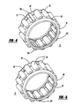
- FIG. 5 is a perspective view of a needle roller bearing incorporating compressible needle rollers in accordance with a second embodiment of the present invention.
- FIG. 6 is an end view of a compressible needle roller incorporated into the embodiment of the bearing shown in FIG. 5;
- FIG. 7 is a perspective view of the needle roller shown in FIG. 6.
- a needle roller 32 which is resiliently compressible in response to a load applied to an exterior surface thereof.
- a first embodiment of the needle roller is incorporated into a bearing assembly 31 and is in the form of a generally cylindrical spring pin 32a having a longitudinal slit 33 formed along the length thereof.
- the needle roller is in the form of a spiral-wound pin 32b.
- Rollers 32 may be formed from steel, metal alloys, and/or other suitable materials using known methods.
- the compressible needle rollers 32 may be subjected to a hardening process or other heat treatment as required for a particular application.
- Needle rollers 32 in accordance with the present invention may replace any desired number of conventional needle rollers 34 in a given bearing assembly. However, as seen in FIGS. 4 and 5, in most embodiments at least some conventional needle rollers will be included in the bearing.
- the bearing incorporates two or more compressible needle rollers 32. In a particular embodiment, two compressible needle rollers 32 angularly spaced apart approximately 90° are included in the bearing. Other particular embodiments incorporating three compressible needle rollers (spaced apart for example, approximately 120°) and four compressible needle rollers are also contemplated. Although particular numbers of compressible rollers and roller arrangements may be shown herein for purposes of illustration, it will be understood that any number of compressible rollers and any spatial arrangement of the rollers deemed suitable for a particular application may be employed.
- needle rollers 32 of the present invention Prior to installation of the needle roller bearing into a joint, needle rollers 32 of the present invention are slightly oversized in comparison to conventional needle rollers 34 incorporated into the bearing. When installed in a joint (e.g., the Cardan joint of an intermediate shaft as described above), needle rollers 32 of the present invention are slightly compressed radially. Upon assembly, the oversized compressible needle rollers 32 will conform to the outer diameter of the trunnion 26b and the inside diameter of the hole 44 formed in yoke 24, helping to ensure a correct operational fit between the yoke and the trunnion.
- the compressible needle rollers 32 will tend to resiliently expand or compress in response to forces exerted on the rollers by the trunnions and/or the yoke, thereby taking up clearances resulting from minute differences in the diameters of the other, conventional needle rollers. This aids in preventing rattling of the bearing in the joint.
- a clearance between one or more conventional rollers and a bearing race (or races) in which they roll can be taken up by providing at least one resiliently compressible second roller rollably secured within the bearing, the resiliently compressible roller having an outer diameter greater than an outer diameter of any conventional roller.
- the outer diameter of the compressible roller is sized such that the roller resiliently compresses when the bearing is positioned in the bearing race. Forces generated by compression of the compressible roller then urge the conventional rollers against the surface of the bearing race, thereby taking up the clearances between the conventional rollers and the bearing races.
- Needle rollers as described herein may be formed having dimensions suitable for use in any size of bearing.
- resiliently compressible needle rollers as described herein may be incorporated into bearings suitable for any of a variety of applications utilizing needle roller bearings.
Abstract
Description
- The present invention relates to needle roller bearings and, more particularly, to a roller for a needle roller bearing.
- Needle roller bearings are used in a wide variety of applications. FIGS. 1 and 2 illustrate one such application, wherein the needle roller bearings are incorporated into an
intermediate shaft assembly 10 for connecting a steering wheel of an automobile to a rack-and-pinion gear assembly of an automobile steering system. Referring to FIGS. 1 and 2, theintermediate shaft assembly 10 shown comprises afirst yoke 12, afirst spider assembly 14 rotationally coupled tofirst yoke 12, and a steeringcolumn clamp yoke 16 rotationally coupled tofirst spider 14 to form a first Cardan joint assembly.Shaft assembly 10 also includes aseal 18, a hollowtubular shaft 20, asolid shaft 22 extending from an interior of the tubular shaft, asecond yoke 24 mounted tosolid shaft 22, asecond spider assembly 26 rotationally coupled tosecond yoke 24, and agear clamp yoke 28 rotationally coupled to the second spider. Thesecond yoke 24,second spider 26, andgear clamp yoke 28 combine to form a second Cardan joint assembly coupled tosolid shaft 22. - In the shaft assembly shown in FIGS. 1 and 2,
first spider 14 andsecond spider 26 are basically identical. Therefore, the following description ofspider 26 is equally applicable tospider 14. As seen in FIG. 2, eachspider 26 has acentral hub 26a and a plurality oftrunnions 26b extending from the hub. A needle roller bearing 30 as shown in FIG. 3 is mounted to each oftrunnions 26b. As seen in FIG. 3, each needle roller bearing 30 comprises a plurality of conventionalsolid needle rollers 34 and acage 36. Cage 36 may be a plastic molded type cage or a stamped sheet metal type cage that includes spacedend rings cross bars 42 to form a plurality of roller receiving windows. -
Needle rollers 34 run directly along an interior cylindrical surface (not shown) inside a hole 44 (FIG. 1) formed inyoke 24. -
Needle rollers 34 also run directly along an exterior cylindrical surface (not shown) formed along eachtrunnion 26b ofspider 26. These interior surfaces and exterior surfaces form inner and outer races for theneedle rollers 34. - In existing joint assemblies of the type just described, differences in the diameters of the needle rollers mounted in a given bearing can cause a pronounced rattling of the bearing in the joint, resulting from intermittent contact between undersized needle rollers and the trunnion and/or yoke during operation of the joint. To help prevent this rattling, the diameters of the needle rollers and the diameters of the portions of the trunnions contacting the needle rollers must be held to within very tight tolerances to help ensure noise-free operation of the joint. This greatly increases the expense of the joint.
- In one aspect of the invention, a bearing assembly is provided including at least one needle roller that is resiliently compressible in response to a load applied to an exterior surface thereof.
- In another aspect of the invention, a method is provided for taking up a clearance between at least one first roller of a plurality of first rollers rollably secured within a roller bearing and a bearing race in which the first roller is rollably positioned. The method includes the step of providing at least one resiliently compressible second roller rollably secured within the bearing, the at least one resiliently compressible second roller having an outer diameter greater than an outer diameter of any first roller of the plurality of first rollers, such that the at least one resiliently compressible second roller resiliently compresses when the bearing is positioned in the bearing race. Forces generated by compression of the resiliently compressible second roller urge the at least one first roller against a surface of the bearing race, thereby taking up the clearance between the at least one first roller and the race.
- FIG. 1 is a perspective view of an existing shaft assembly suitable for incorporating a needle roller bearing in accordance with the present invention;
- FIG. 2 is an exploded perspective view of a portion of the shaft assembly shown in FIG. 1;
- FIG. 3 is a perspective view of a bearing incorporating conventional needle rollers;
- FIG. 4 is a perspective view of a needle roller bearing incorporating compressible needle rollers in accordance with a first embodiment of the present invention;
- FIG. 5 is a perspective view of a needle roller bearing incorporating compressible needle rollers in accordance with a second embodiment of the present invention;
- FIG. 6 is an end view of a compressible needle roller incorporated into the embodiment of the bearing shown in FIG. 5; and
- FIG. 7 is a perspective view of the needle roller shown in FIG. 6.
- Referring to FIGS. 4-7, and in accordance with the present invention, a needle roller 32 is provided which is resiliently compressible in response to a load applied to an exterior surface thereof. In FIG. 4, a first embodiment of the needle roller is incorporated into a
bearing assembly 31 and is in the form of a generallycylindrical spring pin 32a having alongitudinal slit 33 formed along the length thereof. In another embodiment (FIGS. 5-7), the needle roller is in the form of a spiral-wound pin 32b. Rollers 32 may be formed from steel, metal alloys, and/or other suitable materials using known methods. The compressible needle rollers 32 may be subjected to a hardening process or other heat treatment as required for a particular application. - Needle rollers 32 in accordance with the present invention may replace any desired number of
conventional needle rollers 34 in a given bearing assembly. However, as seen in FIGS. 4 and 5, in most embodiments at least some conventional needle rollers will be included in the bearing. In one embodiment of the bearing assembly, the bearing incorporates two or more compressible needle rollers 32. In a particular embodiment, two compressible needle rollers 32 angularly spaced apart approximately 90° are included in the bearing. Other particular embodiments incorporating three compressible needle rollers (spaced apart for example, approximately 120°) and four compressible needle rollers are also contemplated. Although particular numbers of compressible rollers and roller arrangements may be shown herein for purposes of illustration, it will be understood that any number of compressible rollers and any spatial arrangement of the rollers deemed suitable for a particular application may be employed. - Prior to installation of the needle roller bearing into a joint, needle rollers 32 of the present invention are slightly oversized in comparison to
conventional needle rollers 34 incorporated into the bearing. When installed in a joint (e.g., the Cardan joint of an intermediate shaft as described above), needle rollers 32 of the present invention are slightly compressed radially. Upon assembly, the oversized compressible needle rollers 32 will conform to the outer diameter of thetrunnion 26b and the inside diameter of thehole 44 formed inyoke 24, helping to ensure a correct operational fit between the yoke and the trunnion. During operation of the joint, the compressible needle rollers 32 will tend to resiliently expand or compress in response to forces exerted on the rollers by the trunnions and/or the yoke, thereby taking up clearances resulting from minute differences in the diameters of the other, conventional needle rollers. This aids in preventing rattling of the bearing in the joint. - Stated another way, a clearance between one or more conventional rollers and a bearing race (or races) in which they roll can be taken up by providing at least one resiliently compressible second roller rollably secured within the bearing, the resiliently compressible roller having an outer diameter greater than an outer diameter of any conventional roller. The outer diameter of the compressible roller is sized such that the roller resiliently compresses when the bearing is positioned in the bearing race. Forces generated by compression of the compressible roller then urge the conventional rollers against the surface of the bearing race, thereby taking up the clearances between the conventional rollers and the bearing races.
- Needle rollers as described herein may be formed having dimensions suitable for use in any size of bearing. In addition, resiliently compressible needle rollers as described herein may be incorporated into bearings suitable for any of a variety of applications utilizing needle roller bearings.
- It will be understood that the foregoing description of the present invention is for illustrative purposes only, and that the various structural and operational features herein disclosed are susceptible to a number of modifications, none of which departs from the spirit and scope of the present invention. The preceding description, therefore, is not meant to limit the scope of the invention. Rather, the scope of the invention is to be determined only by the appended claims and their equivalents.
Claims (11)
- A bearing assembly (31) comprising at least one needle roller (32) that is resiliently compressible in response to a load applied to an exterior surface thereof.
- A shaft assembly (10) including a bearing assembly (31) in accordance with claim 1.
- The shaft assembly (10) of claim 2 wherein the shaft assembly is for connecting a steering wheel of an automobile to a rack-and-pinion gear assembly of an automobile steering system.
- The bearing assembly (31) of claim 1 wherein the needle roller comprises a cylindrical pin (32a) having a longitudinal slit (33) formed along the length thereof.
- The bearing assembly (31) of claim 1 wherein the needle roller comprises a spiral-wound pin (32b).
- The bearing assembly (31) of claim 1 wherein the assembly includes two compressible needle rollers (32).
- The bearing assembly (31) of claim 6 wherein the needle rollers (32) are angularly spaced apart approximately 90°.
- The bearing assembly (31) of claim 1 wherein the assembly includes three compressible needle rollers (32).
- The bearing assembly (31) of claim 1 further comprising a plurality of substantially non-compressible needle rollers (34), each needle roller of the plurality of substantially non-compressible needle rollers (34) having an outer diameter, and wherein the at least one resiliently compressible needle roller (32) has an outer diameter greater than any of the outer diameters of the substantially non-compressible needle rollers (34).
- A universal joint assembly including a bearing assembly (31) in accordance with claim 1.
- A method for taking up a clearance between at least one first roller of a plurality of first rollers rollably secured within a roller bearing and a bearing race in which the first roller is rollably positioned, the method comprising the step of providing at least one resiliently compressible second roller rollably secured within the bearing, the at least one resiliently compressible second roller having an outer diameter greater than an outer diameter of any first roller of the plurality of first rollers, such that the at least one resiliently compressible second roller resiliently compresses when the bearing is positioned in the bearing race, and wherein forces generated by compression of the at least one resiliently compressible second roller urge the at least one first roller against a surface of the bearing race, thereby taking up the clearance between the at least one first roller and the race.
Applications Claiming Priority (1)
| Application Number | Priority Date | Filing Date | Title |
|---|---|---|---|
| US85790006P | 2006-11-09 | 2006-11-09 |
Publications (2)
| Publication Number | Publication Date |
|---|---|
| EP1921334A2 true EP1921334A2 (en) | 2008-05-14 |
| EP1921334A3 EP1921334A3 (en) | 2008-09-17 |
Family
ID=38973141
Family Applications (1)
| Application Number | Title | Priority Date | Filing Date |
|---|---|---|---|
| EP07119697A Withdrawn EP1921334A3 (en) | 2006-11-09 | 2007-10-31 | Needle roller bearing |
Country Status (2)
| Country | Link |
|---|---|
| US (1) | US8033738B2 (en) |
| EP (1) | EP1921334A3 (en) |
Cited By (5)
| Publication number | Priority date | Publication date | Assignee | Title |
|---|---|---|---|---|
| EP2551537A1 (en) | 2011-07-28 | 2013-01-30 | Schaeffler Technologies AG & Co. KG | Idler bearing for a motor vehicle transmission system |
| DE102012207073A1 (en) | 2011-07-28 | 2013-01-31 | Schaeffler Technologies AG & Co. KG | Spur gear differential has rotatable unit having roller bearings which are arranged along circumferential direction around central axis of adjacent rollers, and elastic roller whose diameter is larger than rollers |
| WO2013013844A1 (en) | 2011-07-28 | 2013-01-31 | Schaeffler Technologies AG & Co. KG | Tunnel roller |
| DE102012207070A1 (en) | 2011-07-28 | 2013-01-31 | Schaeffler Technologies AG & Co. KG | Arrangement for backlash-free mounting of shaft in housing of gearbox of vehicle, comprises radial support for roller bearing, where shaft is prestressed in housing between two stops spaced apart in axial direction |
| DE102012207071A1 (en) | 2011-10-28 | 2013-05-02 | Schaeffler Technologies AG & Co. KG | Bearing point for rotatably bearing impeller of torque converter of motor car gear box in housing of primary pump, has roller bearing whose elastic roll is arranged between raceways, and transducer neck supported at housing by clearances |
Families Citing this family (2)
| Publication number | Priority date | Publication date | Assignee | Title |
|---|---|---|---|---|
| DE102012010830A1 (en) * | 2012-06-01 | 2013-12-05 | Borgwarner Inc. | Freewheel arrangement |
| KR101285226B1 (en) * | 2012-06-27 | 2013-07-11 | 연세대학교 산학협력단 | Tolerance compensating nano/micro roller bearing and method for manufacturing the same |
Citations (5)
| Publication number | Priority date | Publication date | Assignee | Title |
|---|---|---|---|---|
| CH278692A (en) * | 1949-04-11 | 1951-10-31 | Hedtmann Wilhelm | Flexible roller bearing. |
| NL7614386A (en) * | 1976-12-24 | 1978-06-27 | Skf Ind Trading & Dev | Crosshead bearings formed as roller bearings - with resilient spiral wound or star-shaped corrugated rollers between shaft stubs and conrod |
| FR2479369A1 (en) * | 1980-04-01 | 1981-10-02 | Torrington France | Journal bearing with caged rollers - uses mix of solid and larger hollow rollers push fit in annular gap to reduce chatter |
| JPH03277809A (en) * | 1990-03-24 | 1991-12-09 | Ntn Corp | Oscillating bearing |
| DE19734980A1 (en) * | 1997-08-13 | 1999-02-18 | Schaeffler Waelzlager Ohg | Gearbox for motor vehicles |
Family Cites Families (18)
| Publication number | Priority date | Publication date | Assignee | Title |
|---|---|---|---|---|
| US828387A (en) * | 1902-08-04 | 1906-08-14 | Hyatt Roller Bearing Co | Flexible roll for roller-bearings. |
| US1887176A (en) * | 1929-04-03 | 1932-11-08 | Gen Motors Corp | Cage for antifriction bearings |
| US1926123A (en) * | 1931-05-25 | 1933-09-12 | Silas A Strickland | Roller bearing cage assembly |
| US2251714A (en) * | 1939-06-21 | 1941-08-05 | Onions John Henry | Roller bearing, particularly for aircraft shock absorbers |
| DE1625595A1 (en) * | 1967-07-27 | 1970-07-16 | Peter Oskar E | Roller bearing that can be inserted directly between the hub and shaft |
| US3757601A (en) * | 1972-06-22 | 1973-09-11 | Gen Motors Corp | Collapsible steering column assembly |
| JPS52156254A (en) * | 1976-06-21 | 1977-12-26 | Suehiro Seikou Kk | Multiplex bearing |
| DE2741057A1 (en) * | 1977-09-13 | 1979-03-15 | Zahnradfabrik Friedrichshafen | DEVICE FOR BEARING SHAFT IN MOTOR VEHICLE STEERING GEARS |
| FR2480878A1 (en) * | 1980-04-21 | 1981-10-23 | Nadella | PRE-STRESSED BEARING DEVICE |
| DE3876092T2 (en) | 1988-05-14 | 1993-03-25 | Chubu Bearing Kk | WAREHOUSE. |
| US5415612A (en) | 1992-06-12 | 1995-05-16 | American Roller Company | Compressible roller |
| JPH06280864A (en) | 1993-03-29 | 1994-10-07 | Ntn Corp | Needle roller bearing |
| DE19544330C2 (en) | 1995-11-28 | 2000-07-27 | Windmoeller & Hoelscher | Needle roller arrangement with several needle rollers for perforating a continuous material web |
| JP3919366B2 (en) * | 1998-12-07 | 2007-05-23 | Ntn株式会社 | Shell-type needle roller bearings for universal joints for steering |
| DE10046719A1 (en) * | 2000-09-21 | 2002-04-11 | Ina Schaeffler Kg | Gear shift transmission |
| DE10200609A1 (en) * | 2002-01-10 | 2003-07-24 | Ina Schaeffler Kg | Electrically assisted power steering for motor vehicles |
| JPWO2003064877A1 (en) * | 2002-01-18 | 2005-05-26 | 日本精工株式会社 | Cross shaft coupling |
| US7614793B2 (en) * | 2002-11-27 | 2009-11-10 | The Anspach Effort, Inc | Needle/roller bearing |
-
2007
- 2007-10-09 US US11/973,775 patent/US8033738B2/en not_active Expired - Fee Related
- 2007-10-31 EP EP07119697A patent/EP1921334A3/en not_active Withdrawn
Patent Citations (5)
| Publication number | Priority date | Publication date | Assignee | Title |
|---|---|---|---|---|
| CH278692A (en) * | 1949-04-11 | 1951-10-31 | Hedtmann Wilhelm | Flexible roller bearing. |
| NL7614386A (en) * | 1976-12-24 | 1978-06-27 | Skf Ind Trading & Dev | Crosshead bearings formed as roller bearings - with resilient spiral wound or star-shaped corrugated rollers between shaft stubs and conrod |
| FR2479369A1 (en) * | 1980-04-01 | 1981-10-02 | Torrington France | Journal bearing with caged rollers - uses mix of solid and larger hollow rollers push fit in annular gap to reduce chatter |
| JPH03277809A (en) * | 1990-03-24 | 1991-12-09 | Ntn Corp | Oscillating bearing |
| DE19734980A1 (en) * | 1997-08-13 | 1999-02-18 | Schaeffler Waelzlager Ohg | Gearbox for motor vehicles |
Cited By (6)
| Publication number | Priority date | Publication date | Assignee | Title |
|---|---|---|---|---|
| EP2551537A1 (en) | 2011-07-28 | 2013-01-30 | Schaeffler Technologies AG & Co. KG | Idler bearing for a motor vehicle transmission system |
| EP2551538A1 (en) | 2011-07-28 | 2013-01-30 | Schaeffler Technologies AG & Co. KG | Radial bearing for an idler of a motor vehicle transmission system |
| DE102012207073A1 (en) | 2011-07-28 | 2013-01-31 | Schaeffler Technologies AG & Co. KG | Spur gear differential has rotatable unit having roller bearings which are arranged along circumferential direction around central axis of adjacent rollers, and elastic roller whose diameter is larger than rollers |
| WO2013013844A1 (en) | 2011-07-28 | 2013-01-31 | Schaeffler Technologies AG & Co. KG | Tunnel roller |
| DE102012207070A1 (en) | 2011-07-28 | 2013-01-31 | Schaeffler Technologies AG & Co. KG | Arrangement for backlash-free mounting of shaft in housing of gearbox of vehicle, comprises radial support for roller bearing, where shaft is prestressed in housing between two stops spaced apart in axial direction |
| DE102012207071A1 (en) | 2011-10-28 | 2013-05-02 | Schaeffler Technologies AG & Co. KG | Bearing point for rotatably bearing impeller of torque converter of motor car gear box in housing of primary pump, has roller bearing whose elastic roll is arranged between raceways, and transducer neck supported at housing by clearances |
Also Published As
| Publication number | Publication date |
|---|---|
| EP1921334A3 (en) | 2008-09-17 |
| US8033738B2 (en) | 2011-10-11 |
| US20080112662A1 (en) | 2008-05-15 |
Similar Documents
| Publication | Publication Date | Title |
|---|---|---|
| US8033738B2 (en) | Needle roller bearing | |
| EP0610782B1 (en) | A wheel hub unit for a vehicle | |
| KR20030009345A (en) | Connection of a wheel hub bearing unit to a motor vehicle suspension standard | |
| US6102579A (en) | Cage or set of rollers for roller bearings | |
| US20050105840A1 (en) | Bearing apparatus for a wheel of vehicle | |
| JP2011027130A (en) | Bearing device for wheel | |
| JP2009150418A (en) | Wheel bearing device | |
| JP2011148409A (en) | Bearing device for wheel | |
| JP5641706B2 (en) | Wheel bearing device | |
| JP2001208054A (en) | Taper roller bearing | |
| DE102013215892A1 (en) | Bearing with a double row polygon bearing | |
| JP4868891B2 (en) | Wheel bearing device | |
| JP2007205573A (en) | Rolling contact bearing device and steering column | |
| JP2005297885A (en) | Bearing ring member for hub unit and its manufacturing method, and hub unit | |
| JP6750331B2 (en) | Method for manufacturing cage for thrust roller bearing | |
| KR101814596B1 (en) | Wheel bearing and sealing apparatus thereof | |
| JP2008223400A (en) | Guide roller for sliding door | |
| JP2006242257A (en) | Bearing device for wheel | |
| JP2009002480A5 (en) | ||
| JP2007327590A (en) | Cross shaft coupling and steering system for vehicle using cross shaft | |
| WO2018055991A1 (en) | Double-row ball bearing | |
| JP4986512B2 (en) | Wheel bearing device | |
| US8393801B2 (en) | Outer ring of tapered roller bearing and tapered roller bearing | |
| JP2006052752A (en) | Bearing unit for wheel | |
| JP2012035798A (en) | Method for manufacturing bearing device for wheel |
Legal Events
| Date | Code | Title | Description |
|---|---|---|---|
| PUAI | Public reference made under article 153(3) epc to a published international application that has entered the european phase |
Free format text: ORIGINAL CODE: 0009012 |
|
| AK | Designated contracting states |
Kind code of ref document: A2 Designated state(s): AT BE BG CH CY CZ DE DK EE ES FI FR GB GR HU IE IS IT LI LT LU LV MC MT NL PL PT RO SE SI SK TR |
|
| AX | Request for extension of the european patent |
Extension state: AL BA HR MK RS |
|
| PUAL | Search report despatched |
Free format text: ORIGINAL CODE: 0009013 |
|
| AK | Designated contracting states |
Kind code of ref document: A3 Designated state(s): AT BE BG CH CY CZ DE DK EE ES FI FR GB GR HU IE IS IT LI LT LU LV MC MT NL PL PT RO SE SI SK TR |
|
| AX | Request for extension of the european patent |
Extension state: AL BA HR MK RS |
|
| 17P | Request for examination filed |
Effective date: 20090317 |
|
| 17Q | First examination report despatched |
Effective date: 20090417 |
|
| AKX | Designation fees paid |
Designated state(s): AT BE BG CH CY CZ DE DK EE ES FI FR GB GR HU IE IS IT LI LT LU LV MC MT NL PL PT RO SE SI SK TR |
|
| STAA | Information on the status of an ep patent application or granted ep patent |
Free format text: STATUS: THE APPLICATION IS DEEMED TO BE WITHDRAWN |
|
| 18D | Application deemed to be withdrawn |
Effective date: 20091028 |