EP2551537A1 - Idler bearing for a motor vehicle transmission system - Google Patents
Idler bearing for a motor vehicle transmission system Download PDFInfo
- Publication number
- EP2551537A1 EP2551537A1 EP12165917A EP12165917A EP2551537A1 EP 2551537 A1 EP2551537 A1 EP 2551537A1 EP 12165917 A EP12165917 A EP 12165917A EP 12165917 A EP12165917 A EP 12165917A EP 2551537 A1 EP2551537 A1 EP 2551537A1
- Authority
- EP
- European Patent Office
- Prior art keywords
- tunnel
- roller
- tunnel roller
- losradlagerung
- motor vehicle
- Prior art date
- Legal status (The legal status is an assumption and is not a legal conclusion. Google has not performed a legal analysis and makes no representation as to the accuracy of the status listed.)
- Granted
Links
Images


Classifications
-
- F—MECHANICAL ENGINEERING; LIGHTING; HEATING; WEAPONS; BLASTING
- F16—ENGINEERING ELEMENTS AND UNITS; GENERAL MEASURES FOR PRODUCING AND MAINTAINING EFFECTIVE FUNCTIONING OF MACHINES OR INSTALLATIONS; THERMAL INSULATION IN GENERAL
- F16C—SHAFTS; FLEXIBLE SHAFTS; ELEMENTS OR CRANKSHAFT MECHANISMS; ROTARY BODIES OTHER THAN GEARING ELEMENTS; BEARINGS
- F16C27/00—Elastic or yielding bearings or bearing supports, for exclusively rotary movement
- F16C27/08—Elastic or yielding bearings or bearing supports, for exclusively rotary movement primarily for axial load, e.g. for vertically-arranged shafts
-
- F—MECHANICAL ENGINEERING; LIGHTING; HEATING; WEAPONS; BLASTING
- F16—ENGINEERING ELEMENTS AND UNITS; GENERAL MEASURES FOR PRODUCING AND MAINTAINING EFFECTIVE FUNCTIONING OF MACHINES OR INSTALLATIONS; THERMAL INSULATION IN GENERAL
- F16C—SHAFTS; FLEXIBLE SHAFTS; ELEMENTS OR CRANKSHAFT MECHANISMS; ROTARY BODIES OTHER THAN GEARING ELEMENTS; BEARINGS
- F16C19/00—Bearings with rolling contact, for exclusively rotary movement
- F16C19/22—Bearings with rolling contact, for exclusively rotary movement with bearing rollers essentially of the same size in one or more circular rows, e.g. needle bearings
- F16C19/34—Bearings with rolling contact, for exclusively rotary movement with bearing rollers essentially of the same size in one or more circular rows, e.g. needle bearings for both radial and axial load
- F16C19/38—Bearings with rolling contact, for exclusively rotary movement with bearing rollers essentially of the same size in one or more circular rows, e.g. needle bearings for both radial and axial load with two or more rows of rollers
- F16C19/381—Bearings with rolling contact, for exclusively rotary movement with bearing rollers essentially of the same size in one or more circular rows, e.g. needle bearings for both radial and axial load with two or more rows of rollers with at least one row for radial load in combination with at least one row for axial load
-
- F—MECHANICAL ENGINEERING; LIGHTING; HEATING; WEAPONS; BLASTING
- F16—ENGINEERING ELEMENTS AND UNITS; GENERAL MEASURES FOR PRODUCING AND MAINTAINING EFFECTIVE FUNCTIONING OF MACHINES OR INSTALLATIONS; THERMAL INSULATION IN GENERAL
- F16C—SHAFTS; FLEXIBLE SHAFTS; ELEMENTS OR CRANKSHAFT MECHANISMS; ROTARY BODIES OTHER THAN GEARING ELEMENTS; BEARINGS
- F16C19/00—Bearings with rolling contact, for exclusively rotary movement
- F16C19/22—Bearings with rolling contact, for exclusively rotary movement with bearing rollers essentially of the same size in one or more circular rows, e.g. needle bearings
- F16C19/44—Needle bearings
-
- F—MECHANICAL ENGINEERING; LIGHTING; HEATING; WEAPONS; BLASTING
- F16—ENGINEERING ELEMENTS AND UNITS; GENERAL MEASURES FOR PRODUCING AND MAINTAINING EFFECTIVE FUNCTIONING OF MACHINES OR INSTALLATIONS; THERMAL INSULATION IN GENERAL
- F16C—SHAFTS; FLEXIBLE SHAFTS; ELEMENTS OR CRANKSHAFT MECHANISMS; ROTARY BODIES OTHER THAN GEARING ELEMENTS; BEARINGS
- F16C33/00—Parts of bearings; Special methods for making bearings or parts thereof
- F16C33/30—Parts of ball or roller bearings
- F16C33/34—Rollers; Needles
-
- F—MECHANICAL ENGINEERING; LIGHTING; HEATING; WEAPONS; BLASTING
- F16—ENGINEERING ELEMENTS AND UNITS; GENERAL MEASURES FOR PRODUCING AND MAINTAINING EFFECTIVE FUNCTIONING OF MACHINES OR INSTALLATIONS; THERMAL INSULATION IN GENERAL
- F16C—SHAFTS; FLEXIBLE SHAFTS; ELEMENTS OR CRANKSHAFT MECHANISMS; ROTARY BODIES OTHER THAN GEARING ELEMENTS; BEARINGS
- F16C2361/00—Apparatus or articles in engineering in general
- F16C2361/61—Toothed gear systems, e.g. support of pinion shafts
Definitions
- the invention relates to a Losradlagerung for a motor vehicle transmission having at least one via a radial bearing mounted on a gear shaft idler gear, wherein perpendicular to an axis of the gear shaft, a first stop is arranged and at least a first thrust bearing between the first stop and the idler gear is arranged the first thrust bearing has rolling elements.
- Losradlager are roller bearings with which idler gears are rotatably mounted radially relative to a shaft. Such arrangements with radial bearings are in DE - AS - 1 575 611 described. In addition, in DE - AS - 1 575 611 also described the problems with axial bearings of loose wheels. So shows eg JP02163509A a Losradlagerung a motor vehicle transmission with a radial bearing and with a thrust bearing.
- Losradlagerungen The peculiarity in Losradlagerungen is the fact that they rotate almost no load when the idler gears are dragged rotating without torque transmission on the gear shaft, and record almost stationary standing high loads when the respective gear is coupled to the gear shaft.
- the problems associated with these features are known to those skilled in the art and, for example, in DE-AS - 1 575 611 portrayed.
- Axial bearings must always be used as a loose-wheel bearing if axial forces also act on the idler gears because the roller bearings used for the radial bearing of the idler gears can not absorb any axial forces.
- the so-called axial thrust on the loose wheels is known to be caused, for example, on idler gears with helical gearing or by screwing the rollers of the radial bearing.
- the rollers of thrust bearings tend to rotate in almost load-free operating conditions for slippage and for so-called smearing (scuffing) on the raceways.
- the idler wheels can travel undefined within the distance given by axial play during the towed operating state and undefined. Therefore, axial roller bearings must always be preloaded with a preload even in load-free operation.
- the invention has for its object to provide a radial bearing and a Losradlagerung for a loose wheel of a motor vehicle transmission, with which the aforementioned disadvantages can be avoided.
- the first thrust bearing has at least one tunnel roller.
- An embodiment of the invention provides that the Losradlagerung is arranged for a motor vehicle transmission second thrust bearing between a second stop and the idler gear, which preferably also has a tunnel roller.
- the axial bearings preferably each have at least two tunnel rollers in a cage.
- the outer diameter of the at least one tunnel roller is preferably dimensioned such that the idler gear axially biased positionable on the transmission shaft, so that no undefined axial displacement of the idler gear is possible.
- the tunnel rollers have an outer diameter which is slightly larger than the diameter of the other rollers in the bearing. The value by which the diameter is larger, corresponds to the maximum possible axial clearance plus a correction measure, which receives the bias of the thrust bearing assembly and in which the increase in the game can be taken into account by different thermal expansion.
- the idler gear is axially restrained between the thrust bearings. This allows individual positioning the idler gear in the transmission, as preferably centrally in the axial space, so that the friction and the drag torque can be optimized and on the other hand, the oil flow is improved.
- the first thrust bearing and the second thrust bearing each have a cage, which holds a plurality of rolling elements and at least one tunnel roller rolling, wherein the at least one tunnel roller has a larger outer diameter than the rolling elements.
- a first embodiment of the invention provides that the first thrust bearing and the second thrust bearing each rollingly supports at least two tunnel rollers, wherein the at least two tunnel rollers are then evenly distributed on the circumference of the first thrust bearing and the second thrust bearing each rollingly supports at least two tunnel rollers, wherein the at least two tunnel rollers are then evenly distributed on the circumference of the first thrust bearing and the second thrust bearing each rollingly supports at least two tunnel rollers, wherein the at least two tunnel rollers are then evenly distributed on the circumference of the first thrust bearing and the second thrust bearing each rollingly supports at least two tunnel rollers, wherein the at least two tunnel rollers are then evenly distributed on the circumference of the first thrust bearing and the second thrust bearing each rollingly supports at least two tunnel rollers, wherein the at least two tunnel rollers are then evenly distributed on the circumference of the first thrust bearing and the second thrust bearing each rollingly supports at least two tunnel rollers, wherein the at least two tunnel rollers are then evenly distributed on the circumference of the first thrust bearing and the second thrust bearing each rollingly supports at least two tunnel roller
- first and second thrust bearing each with at least one tunnel roller and / or disc springs, wherein the disc springs are elastically biased as well as tunnel rollers. It is also conceivable that a first thrust bearing with at least one tunnel roller and a second spring-loaded thrust bearing with disc springs are used.
- Idler gears are gears that are arranged on a transmission shaft and that rotate in no-load conditions relative to the transmission shaft, for example to a transmission mainshaft.
- the idler gears are in constant meshing with another gear, which is usually stuck to another gear shaft of a motor vehicle transmission.
- On the transmission shaft sit several of the idler gears, each of which meshing with one of the gears on the further gear shaft stands.
- Idler gears are acted upon or dragged depending on the switching state of the respective sitting on the other gear shaft gear with torques. When a gear is engaged, one of the idler gears is coupled torsionally rigid with the transmission mainshaft.
- the further transmission shaft is driven by a transmission input shaft and with her sitting on the other gear shaft gears, being transmitted via one of the gears torques on the coupled with the transmission shaft idler gear and thus to the transmission shaft.
- the other of the idler gears are dragged load-free by the driven gears of the other transmission shaft.
- the torsionally rigid connection between the idler gear and the transmission mainshaft is disengaged and engaged between another one of the idler gears and the transmission shaft.
- roller bearings in the form of roller bearings.
- the roller bearings consist of rollers and usually also of cages.
- Rolls are in their basic form externally cylindrical rotationally symmetrical body, with two end faces.
- the lateral surfaces can be performed differently from the outer cylindrical basic shape spherical.
- the front sides are flat, optionally concave or convex. It may also be provided in addition hollow roles without slot.
- the roles of the loose wheel bearings are usually needles.
- the rollers are held and guided in the cages. In radial bearings, the rollers are arranged with their axes of rotation to each other and to the axis of rotation of the bearing parallel or slightly crossed.
- raceways of the rolling bearings are either cylindrical surface portions on the gear shafts or in gears or are formed by the surfaces of bearing rings.
- the idler bearing has a cage having a plurality of needles and optionally one, two or at least three tunnel rollers.
- the at least three tunnel rollers are evenly distributed around the circumference of the transmission shaft in the cage.
- the radial bearing according to the invention for a loose wheel of a motor vehicle transmission comprises a cage which holds at least one row of rolling elements with a plurality of rolling elements rolling in rolling body pockets.
- Cages of radial bearings are hollow cylindrical one-piece circumferentially closed or once circumferentially slotted in their outlines hollow cylindrical or circumferentially adjacent and circumferentially matching segmental components that have radially continuous windows, so-called pockets.
- the materials of the cages are metals or plastics.
- Cages of thrust bearings are disk-shaped components interspersed with pockets.
- the axes of rotation of the rollers are generally concentric with respect to rays which radiate radially perpendicularly from the axis of rotation of the axial bearing or the idler gear, or are slightly entangled in the plane with the rays to these rays.
- raceways of the rolling bearings are either cylindrical surface portions on the transmission shafts or in gears or are formed by the upper surfaces of bearing rings.
- the raceways are circular ring surfaces which are formed on toothed wheels, on axial disks or on housing or shaft sections.
- tunnel roller in this case hollow rollers, preferably hollow cylindrical rollers to understand. At least one of these tunnel rollers is arranged per row of rolling elements in the circumferential direction between the rollers of the roller bearing. Since the tunnel rollers are hollow cylindrical, they are more elastic than the other rollers, the Grundgroper is filled by their material. Tunnel rollers therefore have noise-damping properties on. Through the slot, the tunnel roller is elastic even more yielding and their damping behavior even better than that of a closed hollow roller.
- the longitudinal slot extends in the radial direction throughout the wall. and thus breaks it completely once in the circumferential direction.
- the longitudinal slot of the tunnel roller in the radial bearing for supporting a loose wheel then passes from the first end to the second end of the tunnel roller along the wall a center angle ⁇ with respect to the cross section of the tunnel roller to 360 °.
- the entire circumference of the lateral surface is described in arbitrary cross sections (transverse to the axis of rotation of the tunnel roller) by the full angle of 360 °.
- the invention thus provides that the slot extends from the beginning to the end and back so that it covers the jacket in the circumferential direction at most once.
- the embodiment of the invention provides that the slot extends over less than half of the lateral surface, ie from the first end to the second End of the tunnel roller along the wall of the tunnel roller a center angle ( ⁇ ) with respect to the cross section of the tunnel roller of less than 180 ° sweeps.
- the limitation on the peripheral region of 180 ° also has an advantageous effect on the production of a tunnel roll of this type, which in this case can be bent from flat material.
- the cut ends of the cylindrically curved flat material are supplied to each other until they face each other in the circumferential direction at intervals, which justifies the widths of the slot.
- Tunnel rollers whose longitudinal slot, however, extends almost over the entire circumference (mid-point angle up to 360 °), however, need to be spirally wound in the approach, which is technically complex in terms of production, if rolls are to be produced with high accuracies.
- the tunnel roll is provided with a longitudinal slot extending from a first end of the tunnel roll to a second end of the tunnel roll, which is inclined at an angle to an axis, either the axis of rotation or parallel to the axis of rotation of the tunnel roll in a wall of the tunnel roll.
- the angles need not be equal to each other in the course of the slot. It may therefore also be that the slit is curved or jagged or arbitrarily deflects the direction alternately because it deflects in any direction and at different angles from the parallel line.
- the European patent application EP 1 921 334 A2 shows a needle bearing. At least one needle of the needle bearing is designed elastically-yielding, if a load is exerted on the outer surface of the needle bearing.
- the elastically deformable needle has a slightly larger outer diameter than the other non-elastically deformable needles.
- the elastic compliance of the needles is achieved in that the needles have a hollow bore and along the length of the needles parallel to the generatrices and the axis of rotation a longitudinal slot is introduced, which runs straight along the wall of the needle.
- the thus formed elastic-compliant needle has the one disadvantage that the straight slot is in the rolling movement of the bearing over its entire length with the edges of the slot in rolling contact with the Wälzlaufbahn.
- Such bearings are only low load and may rotate only at low speeds or only pivoting because the edge contact generated in the rolling contact very high voltage spikes, whereby the rollers and Wälzlaufmaschine can be damaged.
- the slot once per revolution on each of the Wälzlaufmaschine generates disturbing noises.
- the tunnel rollers elastically spring under load in a contact zone and roll on this, which can be described with a contact line with line contact on the Wälzlaufbahnen, the contact line is aligned in the ideal case parallel to the axis of rotation of the tunnel roller.
- the advantage of the oblique orientation of the slot is that upon rotation of the bearing and rolling of the tunnel roller not the entire slot at one time in line contact with the respective Wälzlaufbahnen, but only the part of the slot at the intersection with the contact line. This prevents wear and reduces noise.
- the ratio of outside diameter to wall thickness determines the elasticity with which the tunnel roll reacts.
- the tunnel roller must be resilient enough to be mounted under preload in the camp and to spring under high loads on the diameter of the other rollers.
- the tunnel roller must also be stiff enough to ensure the freedom of play of the radial bearing.
- a quotient of the wall thickness and the outer diameter preferably has a value of 0.04 to 0.2.
- the type of roll is determined by a ratio of the length of the tunnel roll to the outside diameter. Needles are rollers whose length is at least three times their nominal diameter of the outer lateral surface. Cylindrical rollers are accordingly rollers whose length is less than three times the nominal diameter of the roller.
- this ratio in the case of tunnel rollers also has an influence on the stiffness or elasticity, if the wall thickness is taken into account.
- the quotient of the length of the tunnel roll and its outer diameter preferably corresponds to a value of 0.8 to 4.0.
- the slot must be so wide in the circumferential direction that the tunnel rollers can freely deflect radially and peripherally on the radial dimension of the other rollers.
- the longitudinal slot mounted in the outer wall of the tunnel roller therefore preferably has a width with a value of 0.1 mm to zero , 7 mm up.
- the material from which the tunnel roll is made may be 16mnCr5 or Ct45 or 100Cr6 or 1 00CrMn6.
- a first stop 36 and a second stop 35 are arranged in the form of thrust washers for thrust bearings, which are each arranged next to a locking ring 33 which is inserted in an annular groove on the transmission shaft 34.
- a first thrust bearing 30 is arranged between the first stop 36 and the idler gear 20.
- a second thrust bearing 31 is disposed between the second stopper 35 and the idler gear 20.
- Both thrust bearings 30, 31 each have a cage 32, which holds a plurality of rolling elements 25, preferably needles, and at least one tunnel roller 10 rolling.
- the at least one tunnel roller 10 also here has a larger outer diameter 12 (see Fig. 2 ) as the rolling elements 25 on.
- the configuration of the cage 32 or the arrangement of the at least one tunnel roller 10 of the first and second thrust bearings 30, 31 is comparable to the design of the radial bearing 24 4 and 5 , so that here is dispensed with a further description of this. It is merely to be noted that the cage 32 is disc-shaped and axially perforated by pockets. The rolling elements 25 and tunnel rollers 10 are only with their axes of rotation aligned so that they intersect under load in a radial plane, the axis of rotation 11 of the gear shaft 34 together in one point.
Abstract
Description
Die Erfindung betrifft eine Losradlagerung für ein Kraftfahrzeuggetriebe, das mindestens ein über ein Radiallager auf einer Getriebewelle gelagertes Losrad aufweist, wobei senkrecht zu einer Achse der Getriebewelle ein erster Anschlag angeordnet ist und mindestens ein erstes Axiallager zwischen dem ersten Anschlag und dem Losrad angeordnet ist, wobei das erste Axiallager Wälzkörper aufweist.The invention relates to a Losradlagerung for a motor vehicle transmission having at least one via a radial bearing mounted on a gear shaft idler gear, wherein perpendicular to an axis of the gear shaft, a first stop is arranged and at least a first thrust bearing between the first stop and the idler gear is arranged the first thrust bearing has rolling elements.
Losradlager sind Wälzlagerungen, mit denen Losräder gegenüber einer Welle drehbar radial gelagert sind. Derartige Anordnungen mit Radiallagern sind in
Die Besonderheit in Losradlagerungen ist darin zu sehen, dass diese nahezu lastfrei rotieren, wenn die Losräder ohne Drehmomentübertragung auf der Getriebewelle rotierend mitgeschleppt werden, und nahezu still stehend hohe Lasten aufnehmen, wenn das jeweilige Zahnrad mit der Getriebewelle gekuppelt ist. Die Probleme, die mit diesen Besonderheiten verbunden sind, sind dem Fachmann bekannt und beispielsweise in
Axiallager müssen als Losradlager immer dann eingesetzt werden, wenn an den Losrädern auch axiale Kräfte wirken, weil die zur radialen Lagerung der Losräder eingesetzten Rollenlager keine axialen Kräfte aufnehmen können.Axial bearings must always be used as a loose-wheel bearing if axial forces also act on the idler gears because the roller bearings used for the radial bearing of the idler gears can not absorb any axial forces.
Der sogenannte Axialschub an den Losrädern entsteht bekanntermaßen zum Beispiel an Losrädern mit Schrägverzahnung oder durch das Schrauben der Rollen der Radiallagerung. Aus
Eine Anordnung mit spielfrei vorgespannten radialen Losradlagerungen zeigt
Weiterhin ist auch bekannt, dass bei Betrieb der Losradlagerungen hochfrequente Schwingungen entstehen, die als Geräusche das sogenannte Losradkreischen hervorrufen.Furthermore, it is also known that during operation of the Losradlagerungen high-frequency vibrations arise that cause the so-called Losradkreischen as noises.
Der Erfindung liegt die Aufgabe zugrunde, ein Radiallager und eine Losradlagerung für ein Losrad eines Kraftfahrzeuggetriebes zu schaffen, mit denen die vorgenannten Nachteile vermieden werden können.The invention has for its object to provide a radial bearing and a Losradlagerung for a loose wheel of a motor vehicle transmission, with which the aforementioned disadvantages can be avoided.
Die Aufgabe wird nach den Merkmalen des Anspruchs 1 gelöst.The object is solved according to the features of claim 1.
Das erste Axiallager weist mindestens eine Tunnelrolle auf.The first thrust bearing has at least one tunnel roller.
Eine Ausgestaltung der Erfindung sieht vor, dass die Losradlagerung für ein Kraftfahrzeuggetriebe zweites Axiallager zwischen einem zweiten Anschlag und dem Losrad angeordnet ist, welches vorzugsweise auch eine Tunnelrolle aufweist.An embodiment of the invention provides that the Losradlagerung is arranged for a motor vehicle transmission second thrust bearing between a second stop and the idler gear, which preferably also has a tunnel roller.
Die Axiallager weisen bevorzugt jeweils mindestens zwei Tunnelrollen in einem Käfig auf.The axial bearings preferably each have at least two tunnel rollers in a cage.
Unabhängig von der Anzahl der Tunnelrollen im Käfig, ist der Außendurchmesser der mindestens einen Tunnelrolle vorzugsweise derart bemessen, dass das Losrad axial vorgespannt auf der Getriebewelle positionierbar ist, so dass keine undefinierte Axialverschiebung des Losrades mehr möglich ist. Die Tunnelrollen weisen einen Außendurchmesser auf, der geringfügig größer ist als der Durchmesser der übrigen Rollen im Lager. Der Wert, um den der Durchmesser größer ist, entspricht dem maximal möglichen axialen Spiel zuzüglich eines Korrekturmaßes, das die Vorspannung der Axiallageranordnung erhält und in dem auch die Vergrößerung des Spiels durch unterschiedliche Wärmedehnung berücksichtigt sein können. Dadurch ist das Losrad axial spielfrei zwischen den Axiallagern eingespannt. Dies ermöglicht eine individuelle Positionierung des Losrades im Getriebe, wie vorzugsweise mittig im axialen Bauraum, so dass die Reibung und das Schleppmoment optimiert werden und zum anderen der Ölfluss verbessert wird.Regardless of the number of tunnel rollers in the cage, the outer diameter of the at least one tunnel roller is preferably dimensioned such that the idler gear axially biased positionable on the transmission shaft, so that no undefined axial displacement of the idler gear is possible. The tunnel rollers have an outer diameter which is slightly larger than the diameter of the other rollers in the bearing. The value by which the diameter is larger, corresponds to the maximum possible axial clearance plus a correction measure, which receives the bias of the thrust bearing assembly and in which the increase in the game can be taken into account by different thermal expansion. As a result, the idler gear is axially restrained between the thrust bearings. This allows individual positioning the idler gear in the transmission, as preferably centrally in the axial space, so that the friction and the drag torque can be optimized and on the other hand, the oil flow is improved.
Unter Anschläge können in diesem Zusammenhang alle Bauteile, wie Axialscheiben; Zahnräder, Wellenabsätze oder Anlaufscheiben verstanden werden. Sicherungsringe können auf der Getriebewelle axial in einer Ringnut als axial belastbare Schulter eingesetzt werden und dienen zur Festlegung des Radiallagers. Weiterhin können als Anschläge beispielsweise auch Abstandsscheiben, Distanzscheiben, Laufscheiben, Dichtscheiben, usw. verstanden werden.Under stops in this context, all components, such as axial discs; Gears, shaft heels or thrust washers are understood. Circlips can be used on the transmission shaft axially in an annular groove as an axially resilient shoulder and serve to define the radial bearing. Furthermore, as stops, for example, spacers, spacers, pulleys, sealing discs, etc. are understood.
Erfindungsgemäß weisen das erste Axiallager und das zweite Axiallager jeweils einen Käfig auf, der eine Vielzahl von Wälzkörpern und mindestens eine Tunnelrolle rollend haltert, wobei die mindestens eine Tunnelrolle einen größeren Außendurchmesser als die Wälzkörper besitzt.According to the invention, the first thrust bearing and the second thrust bearing each have a cage, which holds a plurality of rolling elements and at least one tunnel roller rolling, wherein the at least one tunnel roller has a larger outer diameter than the rolling elements.
Eine erste Ausführungsform der Erfindung sieht vor, dass das erste Axiallager und das zweite Axiallager jeweils mindestens zwei Tunnelrollen rollend haltert, wobei die mindestens zwei Tunnelrollen dann gleich verteilt am Umfang desA first embodiment of the invention provides that the first thrust bearing and the second thrust bearing each rollingly supports at least two tunnel rollers, wherein the at least two tunnel rollers are then evenly distributed on the circumference of the
Denkbar ist aber auch, das erste und zweite Axiallager mit jeweils mindestens einer Tunnelrolle und/oder mit Tellerfedern vorzuspannen, wobei die Tellerfedern ebenso wie Tunnelrollen elastisch vorgespannt sind. Ebenso ist denkbar, dass ein erstes Axiallager mit mindestens einer Tunnelrolle und ein zweites angefedertes Axiallager mit Tellerfedern eingesetzt werden.It is also conceivable to bias the first and second thrust bearing, each with at least one tunnel roller and / or disc springs, wherein the disc springs are elastically biased as well as tunnel rollers. It is also conceivable that a first thrust bearing with at least one tunnel roller and a second spring-loaded thrust bearing with disc springs are used.
Losräder sind Zahnräder, die auf einer Getriebewelle angeordnet sind und die in lastfreien Zuständen relativ zur Getriebewelle, beispielsweise zu einer Getriebehauptwelle, rotieren. Die Losräder stehen im ständigen Zahneingriff mit einem weiteren Zahnrad, das in der Regel fest auf einer weiteren Getriebewelle eines Kfz-Getriebes sitzt. Auf der Getriebewelle sitzen mehrere der Losräder, von denen jedes im Zahneingriff mit einem der Zahnräder auf der weiteren Getriebewelle steht. Losräder werden je nach Schaltzustand von dem jeweiligen auf der weiteren Getriebewelle sitzenden Zahnrad mit Drehmomenten beaufschlagt oder mitgeschleppt. Wenn ein Gang eingelegt ist, ist eines der Losräder drehstarr mit der Getriebehauptwelle gekuppelt. Die weitere Getriebewelle ist von einer Getriebeeingangswelle aus angetrieben und mit ihr die auf der weiteren Getriebewelle sitzenden Zahnräder, wobei über eines der Zahnräder Drehmomente auf das mit der Getriebewelle gekuppelte Losrad und damit auf die Getriebewelle übertragen werden. Die anderen der Losräder werden durch die angetriebenen Zahnräder der weiteren Getriebewelle lastfrei mitgeschleppt. Wenn ein anderer Gang geschaltet wird, wird die drehstarre Verbindung zwischen dem Losrad und der Getriebehauptwelle ausgekuppelt und zwischen einem anderen der Losräder und der Getriebewelle eingekuppelt.Idler gears are gears that are arranged on a transmission shaft and that rotate in no-load conditions relative to the transmission shaft, for example to a transmission mainshaft. The idler gears are in constant meshing with another gear, which is usually stuck to another gear shaft of a motor vehicle transmission. On the transmission shaft sit several of the idler gears, each of which meshing with one of the gears on the further gear shaft stands. Idler gears are acted upon or dragged depending on the switching state of the respective sitting on the other gear shaft gear with torques. When a gear is engaged, one of the idler gears is coupled torsionally rigid with the transmission mainshaft. The further transmission shaft is driven by a transmission input shaft and with her sitting on the other gear shaft gears, being transmitted via one of the gears torques on the coupled with the transmission shaft idler gear and thus to the transmission shaft. The other of the idler gears are dragged load-free by the driven gears of the other transmission shaft. When a different gear is shifted, the torsionally rigid connection between the idler gear and the transmission mainshaft is disengaged and engaged between another one of the idler gears and the transmission shaft.
Moderne Losradlagerungen sind Wälzlager in Form von Rollenlagern. Die Rollenlager bestehen aus Rollen und in der Regel auch aus Käfigen. Rollen sind in ihrer Grundform außenzylindrisch ausgebildete rotationssymmetrische Körper, mit zwei Stirnseiten. Die Mantelflächen können von der außenzylindrischen Grundform abweichend ballig ausgeführt sein. Die Stirnseiten sind eben, wahlweise konkav oder konvex. Es können auch zusätzlich hohle Rollen ohne Schlitz vorgesehen sein. Die Rollen der Losradlager sind in der Regel Nadeln. Die Rollen sind in den Käfigen gehalten und geführt. In Radiallagern sind die Rollen mit ihren Rotationsachsen zueinander und zur Rotationsachse des Lagers parallel oder leicht verschränkt angeordnet.Modern Losradlagerungen are rolling bearings in the form of roller bearings. The roller bearings consist of rollers and usually also of cages. Rolls are in their basic form externally cylindrical rotationally symmetrical body, with two end faces. The lateral surfaces can be performed differently from the outer cylindrical basic shape spherical. The front sides are flat, optionally concave or convex. It may also be provided in addition hollow roles without slot. The roles of the loose wheel bearings are usually needles. The rollers are held and guided in the cages. In radial bearings, the rollers are arranged with their axes of rotation to each other and to the axis of rotation of the bearing parallel or slightly crossed.
Die Laufbahnen der Wälzlager sind entweder zylindrische Oberflächenabschnitte auf den Getriebewellen bzw. in Zahnrädern oder werden durch die Oberflächen von Lagerringen gebildet.The raceways of the rolling bearings are either cylindrical surface portions on the gear shafts or in gears or are formed by the surfaces of bearing rings.
Mit der erfindungsgemäßen Tunnelrolle kann auch ein radial spielfreies Rollen-oder Nadellager einer Losradlagerung versehen werden. Das Losradlager weist einen Käfig auf, der eine Vielzahl von Nadeln und wahlweise eine, zwei oder mindestens drei Tunnelrollen haltert. Die mindestens drei Tunnelrollen sind dabei gleichmäßig verteilt am Umfang der Getriebewelle im Käfig angeordnet.With the tunnel roller according to the invention also a radial play-free roller or needle roller bearing a Losradlagerung can be provided. The idler bearing has a cage having a plurality of needles and optionally one, two or at least three tunnel rollers. The at least three tunnel rollers are evenly distributed around the circumference of the transmission shaft in the cage.
Das erfindungsgemäße Radiallager für ein Losrad eines Kraftfahrzeuggetriebes umfasst einen Käfig, der mindestens eine Wälzkörperreihe mit einer Vielzahl von Wälzkörpern in Wälzkörpertaschen rollend haltert.The radial bearing according to the invention for a loose wheel of a motor vehicle transmission comprises a cage which holds at least one row of rolling elements with a plurality of rolling elements rolling in rolling body pockets.
Käfige von Radiallagern sind hohlzylindrische einteilig umfangsseitig geschlossene oder einmal umfangsseitig geschlitzte in ihren Umrissen hohlzylindrische oder umfangsseitig benachbarte und umfangsseitig zusammen passende segmentförmige Bauteile, die radial durchgängige Fenster, sogenannte Taschen, aufweisen. Die Werkstoffe der Käfige sind Metalle oder Kunststoffe. Käfige von Axiallagern sind scheibenförmige mit Taschen durchsetzte Bauteile.Cages of radial bearings are hollow cylindrical one-piece circumferentially closed or once circumferentially slotted in their outlines hollow cylindrical or circumferentially adjacent and circumferentially matching segmental components that have radially continuous windows, so-called pockets. The materials of the cages are metals or plastics. Cages of thrust bearings are disk-shaped components interspersed with pockets.
In Axiallagern verlaufen die Rotationsachsen der Rollen in der Regel konzentrisch auf Strahlen, die radial senkrecht von der Rotationsachse des Axiallager bzw. des Losrades abgehen, oder sind in der Ebene mit den Strahlen zu diesen Strahlen leicht verschränkt.In thrust bearings, the axes of rotation of the rollers are generally concentric with respect to rays which radiate radially perpendicularly from the axis of rotation of the axial bearing or the idler gear, or are slightly entangled in the plane with the rays to these rays.
Die Laufbahnen der Wälzlager sind entweder zylindrische Oberflächenabschnitte auf den Getriebewellen bzw. in Zahnrädern oder werden durch die Oberlflächen von Lagerringen gebildet. In Axiallagern sind die Laufbahnen Kreisringflächen, die an Zahnrädern, an Axialscheiben oder an Gehäuse- bzw. Wellenabschnitten ausgebildet sind.The raceways of the rolling bearings are either cylindrical surface portions on the transmission shafts or in gears or are formed by the upper surfaces of bearing rings. In thrust bearings, the raceways are circular ring surfaces which are formed on toothed wheels, on axial disks or on housing or shaft sections.
Als Tunnelrolle sind in diesem Fall hohle Rollen, vorzugsweise hohlzylindrisch ausgebildete Rollen, zu verstehen. Zumindest eine dieser Tunnelrollen ist pro Wälzkörperreihe in Umfangsrichtung zwischen den Rollen des Rollenlagers angeordnet. Da die Tunnelrollen hohlzylindrisch ausgebildet sind, sind diese elastischer als die anderen Rollen, deren Grundköper von ihrem Material ausgefüllt ist. Tunnelrollen weisen deshalb Geräusche dämpfende Eigenschaften auf. Durch den Schlitz ist die Tunnelrolle elastisch noch nachgiebiger und deren Dämpfungsverhalten noch besser als das einer geschlossenen Hohlrolle. Der Längsschlitz erstreckt sich in radialer Richtung durchgängig durch die Wand. und unterbricht diese somit in Umfangsrichtung einmal vollständig.As a tunnel roller in this case hollow rollers, preferably hollow cylindrical rollers to understand. At least one of these tunnel rollers is arranged per row of rolling elements in the circumferential direction between the rollers of the roller bearing. Since the tunnel rollers are hollow cylindrical, they are more elastic than the other rollers, the Grundköper is filled by their material. Tunnel rollers therefore have noise-damping properties on. Through the slot, the tunnel roller is elastic even more yielding and their damping behavior even better than that of a closed hollow roller. The longitudinal slot extends in the radial direction throughout the wall. and thus breaks it completely once in the circumferential direction.
Der Längsschlitz der Tunnelrolle in dem Radiallager zur Lagerung eines Losrades überstreicht danach vom ersten Ende zum zweiten Ende der Tunnelrolle entlang der Wandung einen Mittelpunktswinkel µ bezüglich des Querschnitts der Tunnelrolle bis 360°. Der Mittelpunktswinkel kann in diesem Falle auch als Teilwinkel < 360° oder als Vollwinkel = 360° eines Kreises bezeichnet werden, dessen Kreislinie beispielsweise den Umfang der Tunnelrolle beschreibt. Der gesamte Umfang der Mantelfläche ist in beliebigen Querschnitten (quer zur Rotationsachse der Tunnelrolle) durch den Vollwinkel von 360° beschrieben. Die Erfindung sieht also vor, dass der Schlitz vom Anfang zum Ende und zurück so verläuft, dass er den Mantel in Umfangsrichtung höchstens einmal überstreicht.The longitudinal slot of the tunnel roller in the radial bearing for supporting a loose wheel then passes from the first end to the second end of the tunnel roller along the wall a center angle μ with respect to the cross section of the tunnel roller to 360 °. In this case, the midpoint angle can also be referred to as a partial angle <360 ° or as a full angle = 360 ° of a circle whose circular line describes, for example, the circumference of the tunnel roller. The entire circumference of the lateral surface is described in arbitrary cross sections (transverse to the axis of rotation of the tunnel roller) by the full angle of 360 °. The invention thus provides that the slot extends from the beginning to the end and back so that it covers the jacket in the circumferential direction at most once.
Unregelmäßigkeiten an der vorzugsweise sehr glatten Oberfläche von Wälzkörpern verursachen im Wälzkontakt Spannungsspitzen und fördern Verschleiß an Rollen und Wälzlaufbahnen. Das trifft auch für Schlitze zu. Der spiralförmig ausgebildete Schlitz der Rollen nach
Die Ausgestaltung der Erfindung sieht vor, dass der Schlitz sich über weniger als die Hälfte der Mantelfläche erstreckt, also vom ersten Ende zum zweiten Ende der Tunnelrolle entlang der Wandung der Tunnelrolle einen Mittelpunktswinkel (µ) bezüglich des Querschnitts der Tunnelrolle von weniger als 180° überstreicht. Vorzugsweise erstreckt sich der Schlitz also innerhalb der Hälfte des Umfangs der Mantelfläche, so dass der Teilwinkel vom Vollwinkel 360° abweichend nur < / = 180° ist. Mit einer derartigen Ausbildung ist die Anzahl der Kontaktstellen des Schlitzes bei rotierender Rolle mit den Wälzlaufbahnen noch weiter reduziert.The embodiment of the invention provides that the slot extends over less than half of the lateral surface, ie from the first end to the second End of the tunnel roller along the wall of the tunnel roller a center angle (μ) with respect to the cross section of the tunnel roller of less than 180 ° sweeps. Preferably, the slot thus extends within half of the circumference of the lateral surface, so that the partial angle of the full angle 360 ° deviating only </ = 180 °. With such a design, the number of contact points of the slot with rotating roller with the Wälzlaufbahnen is further reduced.
Die Begrenzung auf den Umfangsbereich von 180° wirkt sich auch vorteilhaft auf die Fertigung einer Tunnelrolle dieses Typs aus, die in diesem Fall aus Flachmaterial gebogen werden kann. Dabei werden die Schnittenden des zylindrisch gebogenen Flachmaterials solange aufeinander zugeführt bis diese sich in Umfangsrichtung mit Abständen gegenüberliegen, die die Breiten des Schlitz begründet. Tunnelrollen, deren Längsschlitz sich dagegen nahezu über den gesamten Umfang erstreckt (Mittelspunktswinkel bis 360°) müssen dagegen im Ansatz spiralförmig gewickelt werden, was fertigungstechnisch aufwändiger ist, wenn Rollen mit hohen Genauigkeiten hergestellt werden sollen.The limitation on the peripheral region of 180 ° also has an advantageous effect on the production of a tunnel roll of this type, which in this case can be bent from flat material. In this case, the cut ends of the cylindrically curved flat material are supplied to each other until they face each other in the circumferential direction at intervals, which justifies the widths of the slot. Tunnel rollers whose longitudinal slot, however, extends almost over the entire circumference (mid-point angle up to 360 °), however, need to be spirally wound in the approach, which is technically complex in terms of production, if rolls are to be produced with high accuracies.
Die Tunnelrolle ist mit einem von einem ersten Ende der Tunnelrolle zu einem zweiten Ende der Tunnelrolle verlaufenden Längsschlitz versehen, der unter einem Winkel zu einer Achse, entweder der Rotationsachse oder zu einer Parallelen der Rotationsachse der Tunnelrolle in einer Wandung der Tunnelrolle geneigt. Also ist der Schlitz nicht achsparallel zur Rotationsachse der Tunnelrolle ausgerichtet, sondern verläuft so schräg zu dieser, dass der mit Winkeln α zu der Rotationsachse der Tunnelrolle von einem ersten Ende der Tunnelrolle zu einem zweiten Ende der Tunnelrolle verläuft, welche vorzugsweise 1 ° = / < α < / =45° sind. Die Winkel müssen im Verlauf des Schlitzes nicht gleich zueinander sein. Es kann also auch sein, dass der Schlitz kurvenartig oder zackenartig verläuft oder beliebig die Richtung wechselnd auslenkt weil er in beliebige Richtungen und mit verschiedenen Winkeln von der parallelen Linie auslenkt.The tunnel roll is provided with a longitudinal slot extending from a first end of the tunnel roll to a second end of the tunnel roll, which is inclined at an angle to an axis, either the axis of rotation or parallel to the axis of rotation of the tunnel roll in a wall of the tunnel roll. Thus, the slot is not aligned axially parallel to the axis of rotation of the tunnel roll, but extends obliquely to this, that runs at angles α to the axis of rotation of the tunnel roll from a first end of the tunnel roll to a second end of the tunnel roll, which preferably 1 ° = / < α </ = 45 °. The angles need not be equal to each other in the course of the slot. It may therefore also be that the slit is curved or jagged or arbitrarily deflects the direction alternately because it deflects in any direction and at different angles from the parallel line.
Die europäische Patentanmeldung
Die Tunnelrollen federn unter Last elastisch in einer Kontaktzone ein und wälzen an dieser ab, welche mit einer Kontaktlinie also mit Linienberührung an den Wälzlaufbahnen beschrieben werden kann, wobei die Kontaktlinie im Idealfall parallel zur Rotationsachse der Tunnelrolle ausgerichtet ist. Der Vorteil der schrägen Ausrichtung des Schlitzes liegt darin, dass bei Rotation des Lagers und Abwälzen der Tunnelrolle nicht der gesamte Schlitz auf einmal im Linienkontakt mit der/den jeweiligen Wälzlaufbahnen steht, sondern nur der Teil des Schlitzes am Schnittpunkt mit der Kontaktlinie. Dadurch wird Verschleiß vermieden und werden Geräusche reduziert.The tunnel rollers elastically spring under load in a contact zone and roll on this, which can be described with a contact line with line contact on the Wälzlaufbahnen, the contact line is aligned in the ideal case parallel to the axis of rotation of the tunnel roller. The advantage of the oblique orientation of the slot is that upon rotation of the bearing and rolling of the tunnel roller not the entire slot at one time in line contact with the respective Wälzlaufbahnen, but only the part of the slot at the intersection with the contact line. This prevents wear and reduces noise.
Das Verhältnis von Außendurchmesser zu Wanddicke bestimmt die Elastizität, mit der die Tunnelrolle reagiert. Einerseits muss die Tunnelrolle elastisch nachgiebig genug sein, um sich unter Vorspannung ins Lager montieren zu lassen und um unter hohen Lasten auch auf den Durchmesser der anderen Rollen einzufedern. Andererseits muss die Tunnelrolle auch steif genug ausgebildet sein um die Spielfreiheit des Radiallagers zu gewährleisten. Ein Quotient aus der Wanddicke und dem Außendurchmesser weist vorzugsweise einen Wert von 0,04 bis 0,2 auf.The ratio of outside diameter to wall thickness determines the elasticity with which the tunnel roll reacts. On the one hand, the tunnel roller must be resilient enough to be mounted under preload in the camp and to spring under high loads on the diameter of the other rollers. On the other hand, the tunnel roller must also be stiff enough to ensure the freedom of play of the radial bearing. A quotient of the wall thickness and the outer diameter preferably has a value of 0.04 to 0.2.
Der Typ der Rolle wird durch ein Verhältnis der Länge der Tunnelrolle zum Außendurchmesser bestimmt. Nadeln sind Rollen, deren Länge mindestens dem Dreifachen ihres Nenndurchmessers der Außenmantelfläche entspricht. Zylinderrollen sind dementsprechend Rollen deren Länge kleiner ist als das Dreifache des Nenndurchmessers der Rolle.The type of roll is determined by a ratio of the length of the tunnel roll to the outside diameter. Needles are rollers whose length is at least three times their nominal diameter of the outer lateral surface. Cylindrical rollers are accordingly rollers whose length is less than three times the nominal diameter of the roller.
Darüber hinaus hat dieses Verhältnis bei Tunnelrollen auch Einfluss auf die Steifigkeit bzw. Elastizität, wenn die Wandstärke mit berücksichtigt wird. Je länger die Rolle, um so steifer ist diese. Je kürzer umso elastischer ist deren Reaktion. So ist es denkbar, die Steifigkeit der Tunnelrollen und damit den Grad der Spieleinstellung des Rollenlagers dadurch zu beeinflussen, dass die Tunnelrolle(n) im Lager länger oder kürzer als die üblichen Rollen sind. Vorzugsweise entspricht der Quotient aus der Länge der Tunnelrolle und deren Außendurchmesser einem Wert von 0,8 bis 4,0.In addition, this ratio in the case of tunnel rollers also has an influence on the stiffness or elasticity, if the wall thickness is taken into account. The longer the roll, the stiffer it is. The shorter the more elastic is their reaction. Thus, it is conceivable to influence the rigidity of the tunnel rollers and thus the degree of play adjustment of the roller bearing in that the tunnel roller (s) in the bearing are longer or shorter than the usual roles. The quotient of the length of the tunnel roll and its outer diameter preferably corresponds to a value of 0.8 to 4.0.
Der Schlitz muss in Umfangsrichtung gerichtet so breit sein, dass die Tunnelrollen ungehindert radial und umfangsseitig auf das radiale Maß der übrigen Rollen einfedern können Der in der äußeren Wandung der Tunnelrolle angebrachte Längsschlitz weist deshalb vorzugweise eine Breite mit einem Wert von 0,1 mm bis 0,7 mm auf.The slot must be so wide in the circumferential direction that the tunnel rollers can freely deflect radially and peripherally on the radial dimension of the other rollers. The longitudinal slot mounted in the outer wall of the tunnel roller therefore preferably has a width with a value of 0.1 mm to zero , 7 mm up.
Das Material aus dem die Tunnelrolle gefertigt ist, kann 16mnCr5 oder Ct45-oder 100Cr6 oder 1 00CrMn6 sein.The material from which the tunnel roll is made may be 16mnCr5 or Ct45 or 100Cr6 or 1 00CrMn6.
I Im Folgenden sollen Ausführungsbeispiele die Erfindung und ihre Vorteile anhand der beigefügten Figuren näher erläutern. Die Größenverhältnisse in den Figuren entsprechen nicht immer den realen Größenverhältnissen, da einige Formen vereinfacht und andere Formen zur besseren Veranschaulichung vergrößert im Verhältnis zu anderen Elementen dargestellt sind.In the following, exemplary embodiments are intended to explain the invention and its advantages in more detail with reference to the attached figures. The proportions in the figures do not always correspond to the actual size ratios, as some shapes are simplified and other shapes are shown enlarged in relation to other elements for ease of illustration.
Für gleiche oder gleich wirkende Elemente der Erfindung werden identische Bezugszeichen verwendet. Ferner werden der Übersicht halber nur Bezugszeichen in den einzelnen Figuren dargestellt, die für die Beschreibung der jeweiligen Figur erforderlich sind. Die dargestellten Ausführungsformen stellen lediglich Beispiele dar, wie das erfindungsgemäße Radiallager für ein Losrad eines Kraftfahrzeuggetriebes ausgestaltet sein kann und stellen somit keine abschließende Begrenzung der Erfindung dar.
-
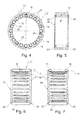
Fig. 1 zeigt eine Ansicht einer Tunnelrolle 10, die bei dem erfindungsgemäßen Radiallager 1 (s.Figuren 4 bis 11das zweite Ende 102 für eine nachfolgende Erläuterung des Mittelpunktswinkels µ sei. Das ersteEnde 101 ist somit in der Darstellung nachFig. 1 nicht zu sehen.Die Tunnelrolle 10 besteht aus einer Wandung 4 und hat eine zentrale Bohrung 5 ausgebildet.Die zentrale Bohrung 5 ist symmetrisch um dieAchse 2der Tunnelrolle 10 angeordnet.Die Wandung 4der Tunnelrolle 10besitzt eine Wanddicke 14.
Ein Längsschlitz 6 verläuft inder Wandung 4 vom ersten Ende 101der Tunnelrolle 10 zum zweiten Ende 102der Tunnelrolle 10. Der Endabschnitt des Längsschlitzes 6 am zweitenEnde 102sei mit 62 bezeichnet. Der Endabschnitt des Längsschlitzes 6 am erstenEnde 101sei mit 61 bezeichnet und, da nicht sichtbar in der Darstellung nachFig. 1 , lediglich als Punktlinie angedeutet.Die Achse 2 verläuft durch den Mittelpunkt des Querschnitts derTunnelrolle 10.Der Längsschlitz 6 überstreicht vom ersten Ende 101 zum zweiten Ende 102der Tunnelrolle 10 entlang der Wandung 4 einen Mittelpunktswinkel µ bezüglich des Querschnitts der Tunnelrolle 10 von weniger als 180°. -
Fig. 2 zeigt den Querschnitt durch dieTunnelrolle 10 entlang der Länge 16der Tunnelrolle 10.Die Tunnelrolle 10 weistein erstes Ende 101 undein zweites Ende 102 auf.Die Tunnelrolle 10 besitzt einen Außendurchmesser 12.Der Außendurchmesser 12 bemisst sich von der Außenseite der Wandung 4der Tunnelrolle 10 zur gegenüberliegenden Außenseite der Wandung 4der Tunnelrolle 10. -
Fig. 3 zeigt eine Seitenansicht der Tunnelrolle 10, wobei der Verlauf des Längsschlitzes 6 entlang der äußeren Wandung 4der Tunnelrolle 10 erkennbar ist.Der Längsschlitz 6 verläuft dabei vom ersten Ende 101 zum zweiten Ende 102der Tunnelrolle 10.Der Längsschlitz 6 ist unter einem Winkel α gegenüber der Achse 2der Tunnelrolle 10 geneigt.Der Längsschlitz 6kann Breiten 18 in Bereichen von 0,1 mm bis 0,7 mm aufweisen und ist an einer Rolle in seinem gesamten Verlauf vorzugsweise mit einem der Werte gleich breit.
Die Tunnelrolle 10 ist bezüglich ihres Außendurchmessers 12 und der Wanddicke 14 bevorzugt derart abgestimmt, dass ein Quotient aus der Wanddicke 14 und dem Außendurchmesser einen Wert zwischen 0,04bis 0,2 aufweist. Analog hierzu ist dieLänge 16der Tunnelrolle 10 in Bezug aufden Außendurchmesser 12 bevorzugt derart abgestimmt, dass ein Quotient aus der Länge 16und dem Außendurchmesser 12 einen Wert zwischen 0,8bis 4,0 aufweist.Der Außendurchmesser 12der Tunnelrolle 10 ist bevorzugt zwischen 2mm bis 10 mm. -
Fig. 4 zeigt eine erste Ausführungsform eines erfindungsgemäßen Radiallagers 24 fürein Losrad 20 eines Kraftfahrzeuggetriebes, das mindestens eine Wälzkörperreihe (sieheFig. 5 bis Fig. 7 ) mit einerVielzahl von Wälzkörpern 25, vorzugsweise Nadeln, inWälzkörpertaschen 28 rollend haltert.Neben den Wälzkörpern 25 sind fünf Tunnelrollen 10 gleich verteilt amUmfang 26 angeordnet, die mit einerFläche 27 des Losrads 20 zusammenwirken.Die fünf Tunnelrollen 10 besitzen einen größeren Außendurchmesser 12 (sieheFig. 2 ) als dieWälzkörper 25. Dies bedeutet, dass bei geringer Lastauf das Radiallager 24die fünf Tunnelrollen 10 in rollendem Kontakt mit der Wälzlaufbahn 27 des Losrads 20 und mit einer Wälzlaufbahn ander Getriebewelle 34 sind. Dadurch wird erreicht, dassdas Radiallager 24 spielfrei ist. Wirkt eine höhere Lastauf das Radiallager 24, werden diefünf Tunnelrollen 10 aufgrund ihrer einfedernd-nachgiebigen Eigenschaften zusammengedrückt, so dass auch dieWälzkörper 25 mit Wälzlaufbahnen im Kontakt stehen. -
Figur 5Fig. 4 mit einer Wälzkörperreihe. Der Außendurchmesser 12 (sieheFig. 2 )der Tunnelrolle 10 ist dabei etwas größer als der Außendurchmesser der Wälzkörper 25.Die Wälzkörper 25 bzw. dieTunnelrollen 10 sindderart im Käfig 22 angeordnet, so dass bei Unterschreiten einerMindestlast am Radiallager 24 diemindestens drei Tunnelrollen 10 spielfreimit der Wälzlaufbahn 27 des Losrades 20 zusammenwirken.Die Wälzkörper 25 bzw. dieTunnelrollen 10 können mit einer Außenhülse (einem Außenring) eines Lagers zusammenwirken. Dieses Lager kann dann in ein Losrad eingesetzt werden, so dass die Außenhülse des Lagers formschlüssig indem Losrad 20 sitzt. -
Figur 6Radiallagers 24, einen sogenannten Losradkäfig, wobei eine Tunnelrolle 10eine Gruppe 11 bildet, die ineiner Wälzkörpertasche 28 angeordnet ist. Insgesamt sind abermindestens drei Gruppen 11 gleich verteilt am Umfang 26 (sieheFig. 4 ) angeordnet, so dass ineiner Wälzkörperreihe 24 neben der Vielzahl der Wälzkörper 25mindestens drei Tunnelrollen 10 angeordnet sind. -
Figur 7 zeigtdas Radiallager 24 nachFig. 6 , bei dem jeweils zwei Tunnelrollen 10eine Gruppe 11 bilden, die ineiner Wälzkörpertasche 28 angeordnet sind. Insgesamt sind aber auch hiermindestens drei Gruppen 11 gleich verteilt am Umfang 26 (sieheFig. 4 ) verteilt. Weitere dargestellte Elemente sind bereits inFig. 7 beschrieben. -
Figur 8 zeigt eine dritte Ausführungsform des erfindungsgemäßen Radiallagers 24 in axialer Schnittansicht, bei dem einer Wälzkörperreihe 24a mit einerVielzahl von Wälzkörpern 25 eine weitere Wälzkörperreihe 29 axial zugeordnet ist, diemindestens drei Tunnelrollen 10 aufweist. Somit ist das inFig. 8 dargestellte Radiallager 24 zweireihig.Sowohl die Wälzköper 25 der ersten Wälzkörperreihe 24a als auch diemindestens drei Tunnelrollen 10 der weiteren Wälzkörperreihe 29 sind in einem gemeinsamen Käfig 22 angeordnet.
Denkbar ist aber auch, dass jede Wälzkörperreihen 24a und 29 einen eigenen Käfig 22 aufweist.Die Käfige 22der Wälzkörperreihen 24 und 29 sind dann lösbar oder nicht lösbar miteinander verbunden oder voneinander frei. -
Figur 9 zeigt eine vierte Ausführungsform des erfindungsgemäßen Radiallagers 24 in axialer Schnittansicht, bei dem zwei Wälzkörperreihen 24a mit jeweils der Vielzahl der Wälzkörper 25 eine weitere Wälzkörperreihe 29 axial zwischengeordnet ist. Auchträgt die Wälzkörperreihe 29 hiermindestens drei Tunnelrollen 10. Andere Ausführungsformen können weitere axiale Zuordnungen der weiteren Wälzkörperreihe 29 vorsehen, so dass diese nicht nur zwischen diebeiden Wälzkörperreihen 24a angeordnet sein muss. Das inFig. 9 dargestellte Radiallager 24 ist somit dreireihig.
Es ist denkbar, dass jede der Reihen in einem separaten Käfig untergebracht ist.
Denkbar ist auch, dass zusätzlichmindestens drei Tunnelrollen 10 in einer oder inbeiden Wälzkörperreihen 24 angeordnet sind. Weitere dargestellte Elemente sind bereits in den vorherigen Figuren beschrieben. -
Figur 10mindestens drei Tunnelrollen 10 in gleich angeordneter Position tragen. -
Figur 11dem nach Figur 10 , bei dem jedoch in den beiden weiteren Wälzkörperreihen 29 die Tunnelrollen 10 jeweils an versetzten Positionen angeordnet sind. Obwohl in der vorstehenden Beschreibung nicht mehr als drei Wälzlagerreihen 24 und 29 dargestellt sind, soll dies nicht als eine Beschränkung der Erfindung aufgefasst werden. Es können auch mehr als drei Wälzlagerreihen 24 und 29 vorgesehen werden, um ein spielfreies und radial vorgespanntes Radiallager 1 fürein Losrad 20 eines Kraftfahrzeuggetriebes zu schaffen, das zudem bei Betrieb geräuschlos ist. -
Figur 12über ein Radiallager 24 auf einer Getriebewelle 34gelagertes Losrad 20.Das Radiallager 24 ist bereits inFig. 4 und 5 beschrieben, so dassdas Radiallager 24 an dieser Stelle nicht noch einmal erläutert wird.
-
Fig. 1 shows a view of atunnel roller 10, which in the radial bearing 1 according to the invention (s.FIGS. 4 to 11 ) Is used, from afirst end 10 1 or asecond end 10 2 ago, this being the general purpose of thesecond end 10 2 for a subsequent explanation of the center angle μ here. Thefirst end 10 1 is thus in the illustration afterFig. 1 not to be seen. Thetunnel roller 10 consists of awall 4 and has acentral bore 5 is formed. Thecentral bore 5 is arranged symmetrically about theaxis 2 of thetunnel roller 10. Thewall 4 of thetunnel roller 10 has awall thickness 14.
Alongitudinal slot 6 extends in thewall 4 from thefirst end 10 1 of thetunnel roller 10 to thesecond end 10 2 of thetunnel roller 10. The end portion of thelongitudinal slot 6 at thesecond end 10 2 is denoted by 6 2 . The end portion of thelongitudinal slot 6 at thefirst end 10 1 is denoted by 6 1 and, since not visible in the illustration toFig. 1 , indicated only as a dotted line. Theaxis 2 extends through the center of the cross section of thetunnel roller 10. Thelongitudinal slot 6 extends from thefirst end 10 1 to thesecond end 10 2 of thetunnel roller 10 along the wall 4 a center angle μ with respect to the cross section of thetunnel roller 10 of less than 180 °. -
Fig. 2 shows the cross section through thetunnel roller 10 along thelength 16 of thetunnel roller 10. Thetunnel roller 10 has afirst end 10 1 and asecond end 102. Thetunnel roller 10 has anouter diameter 12. Theouter diameter 12 is dimensioned from the outer side of thewall 4 of thetunnel roller 10 to the opposite outer side of thewall 4 of thetunnel roller 10. -
Fig. 3 shows a side view of thetunnel roller 10, wherein the course of thelongitudinal slot 6 along theouter wall 4 of thetunnel roller 10 can be seen. Thelongitudinal slot 6 extends from thefirst end 10 1 to thesecond end 10 2 of thetunnel roller 10. Thelongitudinal slot 6 is inclined at an angle α relative to theaxis 2 of thetunnel roller 10. Thelongitudinal slot 6 may havewidths 18 in the range of 0.1 mm to 0.7 mm and is the same width on a roll in its entire course, preferably with one of the values.
Thetunnel roller 10 is preferably tuned with respect to itsouter diameter 12 and thewall thickness 14 such that a quotient of thewall thickness 14 and the outer diameter has a value between 0.04 to 0.2. Analogously, thelength 16 of thetunnel roller 10 with respect to theouter diameter 12 is preferably adjusted such that a quotient of thelength 16 and theouter diameter 12 has a value between 0.8 to 4.0. Theouter diameter 12 of thetunnel roller 10 is preferably between 2 mm to 10 mm. -
Fig. 4 shows a first embodiment of aradial bearing 24 according to the invention for aloose wheel 20 of a motor vehicle transmission, the at least one row of rolling elements (seeFig. 5 to Fig. 7 ) with a plurality of rollingelements 25, preferably needles rollingly holds inWälzkörpertaschen 28. In addition to the rollingelements 25 fivetunnel rollers 10 are evenly distributed around thecircumference 26, which cooperate with asurface 27 of theidler gear 20. The fivetunnel rollers 10 have a larger outer diameter 12 (seeFig. 2 This means that at low load on theradial bearing 24, the fivetunnel rollers 10 in rolling contact with the Wälzlaufbahn 27th of theidler gear 20 and with a Wälzlaufbahn on thetransmission shaft 34. This ensures that theradial bearing 24 is free of play. Acts a higher load on theradial bearing 24, the fivetunnel rollers 10 are compressed due to their resilient-resilient properties, so that the rollingelements 25 are in contact with Wälzlaufbahnen. -
FIG. 5 shows a sectional view of theradial bearing 24Fig. 4 with a row of rolling elements. The outer diameter 12 (seeFig. 2 The rollingelements 25 and thetunnel rollers 10 are arranged in thecage 22, so that falls below a minimum load on theradial bearing 24, the at least threetunnel rollers 10 backlash with theWälzlaufbahn 27 ofLosrades 20 cooperate. The rollingelements 25 and thetunnel rollers 10 can interact with an outer sleeve (an outer ring) of a bearing. This bearing can then be used in a loose wheel, so that the outer sleeve of the bearing sits positively in theidler gear 20. -
FIG. 6 shows an axial sectional section of theradial bearing 24, a so-called Losradkäfig, wherein atunnel roller 10 forms agroup 11 which is arranged in aWälzkörpertasche 28. Overall, however, at least threegroups 11 are evenly distributed on the circumference 26 (seeFig. 4 ), so that in a row of rollingelements 24 in addition to the plurality of rollingelements 25 at least threetunnel rollers 10 are arranged. -
FIG. 7 indicates theradial bearing 24 afterFig. 6 in which in each case twotunnel rollers 10 form agroup 11, which are arranged in a rolling-element pocket 28. Overall, however, at least threegroups 11 are equally distributed on the circumference 26 (seeFig. 4 ). Other illustrated elements are already inFig. 7 described. -
FIG. 8 shows a third embodiment of theradial bearing 24 according to the invention in axial sectional view, in which a rollingbody 24a with a plurality of rollingelements 25, a further row of rollingelements 29 axially assigned is that has at least threetunnel rollers 10. Thus, that is inFig. 8 illustratedradial bearing 24 two rows. Both theWälzköper 25 of the first row of rollingelements 24a and the at least threetunnel rollers 10 of the other row of rollingelements 29 are arranged in acommon cage 22.
It is also conceivable that each row of rollingelements own cage 22. Thecages 22 of the rows of rollingelements -
FIG. 9 shows a fourth embodiment of theradial bearing 24 according to the invention in axial sectional view, in which two rows of rollingelements 24a with each of the plurality of rollingelements 25, a further row of rollingelements 29 is axially interposed. The rollingelement row 29 here also carries at least threetunnel rollers 10. Other embodiments may provide further axial allocations of the further rollingelement row 29 so that it need not only be arranged between the two rows of rollingelements 24a. This inFig. 9 illustratedradial bearing 24 is thus three rows.
It is conceivable that each of the rows is housed in a separate cage.
It is also conceivable that in addition at least threetunnel rollers 10 are arranged in one or both rows of rollingelements 24. Further illustrated elements have already been described in the previous figures. -
FIG. 10 shows a further embodiment of theradial bearing 24 according to the invention in an axial sectional view, in which theWälzköperreihe 24 are associated with the plurality of rollingelements 25 axially on both sides of two further rows of rollingelements 29, each carrying at least threetunnel rollers 10 in the same position. -
FIG. 11 shows an axial sectional view of aradial bearing 24, comparable to the afterFIG. 10 in which, however, thetunnel rollers 10 are each arranged at staggered positions in the two further rows of rollingelements 29. Although not more than three rows of rollingbearings bearings loose wheel 20 of a motor vehicle transmission, which is also noiseless in operation. -
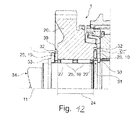
FIG. 12 shows a partial view of a motor vehicle transmission 1 with the Losradlagerung invention in longitudinal section. The idler gear bearing comprises at least oneidler gear 20 mounted on agear shaft 34 via aradial bearing 24. Theradial bearing 24 is already in4 and 5 described, so that theradial bearing 24 is not explained again at this point.
Senkrecht zu einer Achse 11 der Getriebewelle 34 sind ein erster Anschlag 36 und ein zweiter Anschlag 35 in Form von Laufscheiben für Axiallager angeordnet, die jeweils neben einem Sicherungsring 33, der in einer Ringnut auf der Getriebewelle 34 eingesetzt ist, angeordnet sind.Perpendicular to an
Zwischen dem ersten Anschlag 36 und dem Losrad 20 ist ein erstes Axiallager 30 angeordnet. Ebenso ist zwischen dem zweiten Anschlag 35 und dem Losrad 20 ein zweites Axiallager 31 angeordnet. Beide Axiallager 30, 31 weisen jeweils einen Käfig 32 auf, der eine Vielzahl von Wälzkörpern 25, vorzugsweise Nadeln, und mindestens eine Tunnelrolle 10 rollend haltert. Wie auch beim Radiallager 24, weist die mindestens eine Tunnelrolle 10 auch hier einen größeren Außendurchmesser 12 (siehe
Die Ausgestaltung des Käfigs 32 bzw. die Anordnung der mindestens einen Tunnelrolle 10 des ersten und zweiten Axiallagers 30, 31 ist vergleichbar mit der Ausführung des Radiallagers 24 nach
Im Besonderen ist der Außendurchmesser 12 der mindestens einen Tunnelrolle 10 des ersten und zweiten Axiallagers 30, 31 derart bemessen, dass das Losrad 20 axial vorgespannt auf der Getriebewelle 34 positionierbar ist. Somit ist aufgrund des spielfreien und radial vorgespannten Radiallagers 24 und den spielfrei und axial vorgespannten Axiallagern 30, 31 eine Losradlagerung für ein Kraftfahrzeuggetriebe 1 geschaffen, dass bei Betrieb geräuschlos ist und zudem noch Betriebseigenschaften, wie Reibung bzw. Schleppmoment, optimiert.In particular, the
Claims (13)
Applications Claiming Priority (2)
| Application Number | Priority Date | Filing Date | Title |
|---|---|---|---|
| DE102011080021 | 2011-07-28 | ||
| DE102011080027 | 2011-07-28 |
Publications (2)
| Publication Number | Publication Date |
|---|---|
| EP2551537A1 true EP2551537A1 (en) | 2013-01-30 |
| EP2551537B1 EP2551537B1 (en) | 2015-04-15 |
Family
ID=46052570
Family Applications (2)
| Application Number | Title | Priority Date | Filing Date |
|---|---|---|---|
| EP20120165920 Withdrawn EP2551538A1 (en) | 2011-07-28 | 2012-04-27 | Radial bearing for an idler of a motor vehicle transmission system |
| EP20120165917 Not-in-force EP2551537B1 (en) | 2011-07-28 | 2012-04-27 | Idler bearing for a motor vehicle transmission system |
Family Applications Before (1)
| Application Number | Title | Priority Date | Filing Date |
|---|---|---|---|
| EP20120165920 Withdrawn EP2551538A1 (en) | 2011-07-28 | 2012-04-27 | Radial bearing for an idler of a motor vehicle transmission system |
Country Status (1)
| Country | Link |
|---|---|
| EP (2) | EP2551538A1 (en) |
Cited By (2)
| Publication number | Priority date | Publication date | Assignee | Title |
|---|---|---|---|---|
| DE102013217517A1 (en) * | 2013-09-03 | 2015-03-05 | Schaeffler Technologies Gmbh & Co. Kg | Rolling bearings and rolling elements for reducing electrical potentials |
| DE102015215707A1 (en) | 2015-08-18 | 2017-02-23 | Schaeffler Technologies AG & Co. KG | Gearbox bearing designed as a hollow rollers rolling elements |
Families Citing this family (3)
| Publication number | Priority date | Publication date | Assignee | Title |
|---|---|---|---|---|
| DE102016210654A1 (en) | 2016-06-15 | 2017-04-06 | Schaeffler Technologies AG & Co. KG | Gear arrangement for a vehicle |
| DE102016210656A1 (en) | 2016-06-15 | 2017-05-11 | Schaeffler Technologies AG & Co. KG | Gear arrangement for a vehicle |
| DE102016210651B4 (en) | 2016-06-15 | 2022-03-03 | Schaeffler Technologies AG & Co. KG | Gear arrangement with plain bearing device |
Citations (8)
| Publication number | Priority date | Publication date | Assignee | Title |
|---|---|---|---|---|
| DE826384C (en) * | 1949-04-12 | 1952-01-03 | Wilhelm Hedtmann Fa | Elastic bearing, especially needle bearing |
| DE1575611B1 (en) | 1966-06-02 | 1971-04-22 | Skf Kugellagerfabriken Gmbh | MOUNTING OF A FREELY ROTATING GEAR WHEEL ON A GEAR SHAFT OF A MOTOR VEHICLE MANUAL GEARBOX |
| DE7139580U (en) * | 1972-11-09 | Rollway Bearing Co Inc | Roller for a roller bearing | |
| JPH02163509A (en) | 1988-12-15 | 1990-06-22 | Nippon Seiko Kk | Rotary supporting portion |
| DE19734980A1 (en) | 1997-08-13 | 1999-02-18 | Schaeffler Waelzlager Ohg | Gearbox for motor vehicles |
| DE10037401A1 (en) * | 2000-08-01 | 2002-02-14 | Daimler Chrysler Ag | Gear change device for motor vehicle transmissions has moveable change element coupled non-turnable to first transmission element, and coupled via two coupling bodies to first and second transmission elements |
| EP1921334A2 (en) | 2006-11-09 | 2008-05-14 | Delphi Technologies, Inc. | Needle roller bearing |
| DE102007057045A1 (en) * | 2007-11-27 | 2009-05-28 | Schaeffler Kg | Radial bearing for speed change gear of motor vehicle, has rolling body row comprising hollow rollers and balls, where radial pre-load on rollers, balls and needles is achieved by radially inwardly displaced sliding surfaces of outer races |
Family Cites Families (1)
| Publication number | Priority date | Publication date | Assignee | Title |
|---|---|---|---|---|
| CH232973A (en) * | 1942-03-25 | 1944-06-30 | Rheinmetall Borsig Ag | Shaft mounted on the same axis in a tube. |
-
2012
- 2012-04-27 EP EP20120165920 patent/EP2551538A1/en not_active Withdrawn
- 2012-04-27 EP EP20120165917 patent/EP2551537B1/en not_active Not-in-force
Patent Citations (8)
| Publication number | Priority date | Publication date | Assignee | Title |
|---|---|---|---|---|
| DE7139580U (en) * | 1972-11-09 | Rollway Bearing Co Inc | Roller for a roller bearing | |
| DE826384C (en) * | 1949-04-12 | 1952-01-03 | Wilhelm Hedtmann Fa | Elastic bearing, especially needle bearing |
| DE1575611B1 (en) | 1966-06-02 | 1971-04-22 | Skf Kugellagerfabriken Gmbh | MOUNTING OF A FREELY ROTATING GEAR WHEEL ON A GEAR SHAFT OF A MOTOR VEHICLE MANUAL GEARBOX |
| JPH02163509A (en) | 1988-12-15 | 1990-06-22 | Nippon Seiko Kk | Rotary supporting portion |
| DE19734980A1 (en) | 1997-08-13 | 1999-02-18 | Schaeffler Waelzlager Ohg | Gearbox for motor vehicles |
| DE10037401A1 (en) * | 2000-08-01 | 2002-02-14 | Daimler Chrysler Ag | Gear change device for motor vehicle transmissions has moveable change element coupled non-turnable to first transmission element, and coupled via two coupling bodies to first and second transmission elements |
| EP1921334A2 (en) | 2006-11-09 | 2008-05-14 | Delphi Technologies, Inc. | Needle roller bearing |
| DE102007057045A1 (en) * | 2007-11-27 | 2009-05-28 | Schaeffler Kg | Radial bearing for speed change gear of motor vehicle, has rolling body row comprising hollow rollers and balls, where radial pre-load on rollers, balls and needles is achieved by radially inwardly displaced sliding surfaces of outer races |
Cited By (2)
| Publication number | Priority date | Publication date | Assignee | Title |
|---|---|---|---|---|
| DE102013217517A1 (en) * | 2013-09-03 | 2015-03-05 | Schaeffler Technologies Gmbh & Co. Kg | Rolling bearings and rolling elements for reducing electrical potentials |
| DE102015215707A1 (en) | 2015-08-18 | 2017-02-23 | Schaeffler Technologies AG & Co. KG | Gearbox bearing designed as a hollow rollers rolling elements |
Also Published As
| Publication number | Publication date |
|---|---|
| EP2551538A1 (en) | 2013-01-30 |
| EP2551537B1 (en) | 2015-04-15 |
Similar Documents
| Publication | Publication Date | Title |
|---|---|---|
| EP1896740B1 (en) | Multiple-row angular contact antifriction bearing, particularly for mounting the bevel pinion shaft in a motor vehicle rear axle differential | |
| DE102007019482A1 (en) | Multi-row slewing bearings, in particular axial-radial bearings for main bearing of the rotor shaft of a wind turbine | |
| DE102011004706A1 (en) | Tapered roller bearing with cage | |
| EP2551537B1 (en) | Idler bearing for a motor vehicle transmission system | |
| DE102007004998A1 (en) | Pivot bearing arrangement | |
| EP1957811A1 (en) | Radial antifriction bearing, especially single-row grooved antifriction bearing | |
| DE102006044802A1 (en) | Combined sliding ball bearing for supporting shaft in gear construction, has balls and rollers unroll on remaining shoulder surfaces, where bearing is formed as four-point ball bearing, so that running grooves have contact points | |
| DE102005027186B4 (en) | Rolling bearing cage and idler gear bearing | |
| WO2012010656A1 (en) | Rolling bearing assembly comprising a retaining device | |
| EP2753842A1 (en) | Freewheel device | |
| DE2918601A1 (en) | Gearbox spigot bearing cage - has rolling bodies of larger diameter than rollers in some rockets at intervals | |
| DE112004002814B4 (en) | Composite rolling bearing | |
| WO2014094756A1 (en) | Axial bearing arrangement | |
| DE102012207073A1 (en) | Spur gear differential has rotatable unit having roller bearings which are arranged along circumferential direction around central axis of adjacent rollers, and elastic roller whose diameter is larger than rollers | |
| WO1993017252A1 (en) | Silent loose wheel bearing | |
| DE102012207067A1 (en) | Roller bearing in gear box of vehicle, for bearing e.g. idle gear wheel, has one pocket series that is arranged adjacently to rollers in circumferential direction, and another pocket series that is set in free zone of other rollers | |
| DE102008045848A1 (en) | Planetary gear i.e. transmission gear, has planetary wheel formed from two separate planetary wheel parts, where parts are located coaxially adjacent to each other on common axis, and contact stationary inner wheel flange | |
| WO2008068123A1 (en) | Thrust bearing of a dual-clutch transmission | |
| DE102012207071A1 (en) | Bearing point for rotatably bearing impeller of torque converter of motor car gear box in housing of primary pump, has roller bearing whose elastic roll is arranged between raceways, and transducer neck supported at housing by clearances | |
| WO2011020657A1 (en) | Rolling element cage | |
| DE102010011462A1 (en) | Tapered roller bearing with profiled raceway | |
| DE102007035450A1 (en) | wave switches | |
| DE102015224215B4 (en) | Planetary gear, as well as double row ball bearing assembly for this purpose | |
| DE102016222451A1 (en) | Roller bearing and gear device with a roller bearing | |
| DE102015223125B4 (en) | Bearing with two polygon bearings and a two-stage stiffness characteristic |
Legal Events
| Date | Code | Title | Description |
|---|---|---|---|
| PUAI | Public reference made under article 153(3) epc to a published international application that has entered the european phase |
Free format text: ORIGINAL CODE: 0009012 |
|
| 17P | Request for examination filed |
Effective date: 20120427 |
|
| AK | Designated contracting states |
Kind code of ref document: A1 Designated state(s): AL AT BE BG CH CY CZ DE DK EE ES FI FR GB GR HR HU IE IS IT LI LT LU LV MC MK MT NL NO PL PT RO RS SE SI SK SM TR |
|
| AX | Request for extension of the european patent |
Extension state: BA ME |
|
| 17Q | First examination report despatched |
Effective date: 20130118 |
|
| RBV | Designated contracting states (corrected) |
Designated state(s): AL AT BE BG CH CY CZ DE DK EE ES FI FR GB GR HR HU IE IS IT LI LT LU LV MC MK MT NL NO PL PT RO RS SE SI SK SM TR |
|
| RAP1 | Party data changed (applicant data changed or rights of an application transferred) |
Owner name: SCHAEFFLER TECHNOLOGIES GMBH & CO. KG |
|
| GRAP | Despatch of communication of intention to grant a patent |
Free format text: ORIGINAL CODE: EPIDOSNIGR1 |
|
| INTG | Intention to grant announced |
Effective date: 20141216 |
|
| RAP1 | Party data changed (applicant data changed or rights of an application transferred) |
Owner name: SCHAEFFLER TECHNOLOGIES AG & CO. KG |
|
| GRAS | Grant fee paid |
Free format text: ORIGINAL CODE: EPIDOSNIGR3 |
|
| GRAA | (expected) grant |
Free format text: ORIGINAL CODE: 0009210 |
|
| AK | Designated contracting states |
Kind code of ref document: B1 Designated state(s): AL AT BE BG CH CY CZ DE DK EE ES FI FR GB GR HR HU IE IS IT LI LT LU LV MC MK MT NL NO PL PT RO RS SE SI SK SM TR |
|
| REG | Reference to a national code |
Ref country code: GB Ref legal event code: FG4D Free format text: NOT ENGLISH Ref country code: CH Ref legal event code: EP |
|
| REG | Reference to a national code |
Ref country code: IE Ref legal event code: FG4D Free format text: LANGUAGE OF EP DOCUMENT: GERMAN |
|
| REG | Reference to a national code |
Ref country code: AT Ref legal event code: REF Ref document number: 722173 Country of ref document: AT Kind code of ref document: T Effective date: 20150515 |
|
| REG | Reference to a national code |
Ref country code: DE Ref legal event code: R096 Ref document number: 502012002842 Country of ref document: DE Effective date: 20150528 |
|
| REG | Reference to a national code |
Ref country code: NL Ref legal event code: VDEP Effective date: 20150415 |
|
| REG | Reference to a national code |
Ref country code: LT Ref legal event code: MG4D |
|
| PG25 | Lapsed in a contracting state [announced via postgrant information from national office to epo] |
Ref country code: NL Free format text: LAPSE BECAUSE OF FAILURE TO SUBMIT A TRANSLATION OF THE DESCRIPTION OR TO PAY THE FEE WITHIN THE PRESCRIBED TIME-LIMIT Effective date: 20150415 |
|
| PG25 | Lapsed in a contracting state [announced via postgrant information from national office to epo] |
Ref country code: NO Free format text: LAPSE BECAUSE OF FAILURE TO SUBMIT A TRANSLATION OF THE DESCRIPTION OR TO PAY THE FEE WITHIN THE PRESCRIBED TIME-LIMIT Effective date: 20150715 Ref country code: ES Free format text: LAPSE BECAUSE OF FAILURE TO SUBMIT A TRANSLATION OF THE DESCRIPTION OR TO PAY THE FEE WITHIN THE PRESCRIBED TIME-LIMIT Effective date: 20150415 Ref country code: FI Free format text: LAPSE BECAUSE OF FAILURE TO SUBMIT A TRANSLATION OF THE DESCRIPTION OR TO PAY THE FEE WITHIN THE PRESCRIBED TIME-LIMIT Effective date: 20150415 Ref country code: LT Free format text: LAPSE BECAUSE OF FAILURE TO SUBMIT A TRANSLATION OF THE DESCRIPTION OR TO PAY THE FEE WITHIN THE PRESCRIBED TIME-LIMIT Effective date: 20150415 Ref country code: HR Free format text: LAPSE BECAUSE OF FAILURE TO SUBMIT A TRANSLATION OF THE DESCRIPTION OR TO PAY THE FEE WITHIN THE PRESCRIBED TIME-LIMIT Effective date: 20150415 Ref country code: PT Free format text: LAPSE BECAUSE OF FAILURE TO SUBMIT A TRANSLATION OF THE DESCRIPTION OR TO PAY THE FEE WITHIN THE PRESCRIBED TIME-LIMIT Effective date: 20150817 |
|
| PG25 | Lapsed in a contracting state [announced via postgrant information from national office to epo] |
Ref country code: IS Free format text: LAPSE BECAUSE OF FAILURE TO SUBMIT A TRANSLATION OF THE DESCRIPTION OR TO PAY THE FEE WITHIN THE PRESCRIBED TIME-LIMIT Effective date: 20150815 Ref country code: RS Free format text: LAPSE BECAUSE OF FAILURE TO SUBMIT A TRANSLATION OF THE DESCRIPTION OR TO PAY THE FEE WITHIN THE PRESCRIBED TIME-LIMIT Effective date: 20150415 Ref country code: LV Free format text: LAPSE BECAUSE OF FAILURE TO SUBMIT A TRANSLATION OF THE DESCRIPTION OR TO PAY THE FEE WITHIN THE PRESCRIBED TIME-LIMIT Effective date: 20150415 Ref country code: GR Free format text: LAPSE BECAUSE OF FAILURE TO SUBMIT A TRANSLATION OF THE DESCRIPTION OR TO PAY THE FEE WITHIN THE PRESCRIBED TIME-LIMIT Effective date: 20150716 |
|
| REG | Reference to a national code |
Ref country code: CH Ref legal event code: PL |
|
| REG | Reference to a national code |
Ref country code: DE Ref legal event code: R097 Ref document number: 502012002842 Country of ref document: DE |
|
| REG | Reference to a national code |
Ref country code: IE Ref legal event code: MM4A |
|
| PG25 | Lapsed in a contracting state [announced via postgrant information from national office to epo] |
Ref country code: LI Free format text: LAPSE BECAUSE OF NON-PAYMENT OF DUE FEES Effective date: 20150430 Ref country code: MC Free format text: LAPSE BECAUSE OF FAILURE TO SUBMIT A TRANSLATION OF THE DESCRIPTION OR TO PAY THE FEE WITHIN THE PRESCRIBED TIME-LIMIT Effective date: 20150415 Ref country code: EE Free format text: LAPSE BECAUSE OF FAILURE TO SUBMIT A TRANSLATION OF THE DESCRIPTION OR TO PAY THE FEE WITHIN THE PRESCRIBED TIME-LIMIT Effective date: 20150415 Ref country code: DK Free format text: LAPSE BECAUSE OF FAILURE TO SUBMIT A TRANSLATION OF THE DESCRIPTION OR TO PAY THE FEE WITHIN THE PRESCRIBED TIME-LIMIT Effective date: 20150415 Ref country code: IT Free format text: LAPSE BECAUSE OF FAILURE TO SUBMIT A TRANSLATION OF THE DESCRIPTION OR TO PAY THE FEE WITHIN THE PRESCRIBED TIME-LIMIT Effective date: 20150415 Ref country code: CH Free format text: LAPSE BECAUSE OF NON-PAYMENT OF DUE FEES Effective date: 20150430 |
|
| PLBE | No opposition filed within time limit |
Free format text: ORIGINAL CODE: 0009261 |
|
| STAA | Information on the status of an ep patent application or granted ep patent |
Free format text: STATUS: NO OPPOSITION FILED WITHIN TIME LIMIT |
|
| PG25 | Lapsed in a contracting state [announced via postgrant information from national office to epo] |
Ref country code: SK Free format text: LAPSE BECAUSE OF FAILURE TO SUBMIT A TRANSLATION OF THE DESCRIPTION OR TO PAY THE FEE WITHIN THE PRESCRIBED TIME-LIMIT Effective date: 20150415 Ref country code: CZ Free format text: LAPSE BECAUSE OF FAILURE TO SUBMIT A TRANSLATION OF THE DESCRIPTION OR TO PAY THE FEE WITHIN THE PRESCRIBED TIME-LIMIT Effective date: 20150415 Ref country code: RO Free format text: LAPSE BECAUSE OF NON-PAYMENT OF DUE FEES Effective date: 20150415 Ref country code: PL Free format text: LAPSE BECAUSE OF FAILURE TO SUBMIT A TRANSLATION OF THE DESCRIPTION OR TO PAY THE FEE WITHIN THE PRESCRIBED TIME-LIMIT Effective date: 20150415 |
|
| REG | Reference to a national code |
Ref country code: FR Ref legal event code: ST Effective date: 20160205 |
|
| 26N | No opposition filed |
Effective date: 20160118 |
|
| PG25 | Lapsed in a contracting state [announced via postgrant information from national office to epo] |
Ref country code: IE Free format text: LAPSE BECAUSE OF NON-PAYMENT OF DUE FEES Effective date: 20150427 |
|
| PG25 | Lapsed in a contracting state [announced via postgrant information from national office to epo] |
Ref country code: SI Free format text: LAPSE BECAUSE OF FAILURE TO SUBMIT A TRANSLATION OF THE DESCRIPTION OR TO PAY THE FEE WITHIN THE PRESCRIBED TIME-LIMIT Effective date: 20150415 Ref country code: FR Free format text: LAPSE BECAUSE OF NON-PAYMENT OF DUE FEES Effective date: 20150615 |
|
| GBPC | Gb: european patent ceased through non-payment of renewal fee |
Effective date: 20160427 |
|
| PG25 | Lapsed in a contracting state [announced via postgrant information from national office to epo] |
Ref country code: MT Free format text: LAPSE BECAUSE OF FAILURE TO SUBMIT A TRANSLATION OF THE DESCRIPTION OR TO PAY THE FEE WITHIN THE PRESCRIBED TIME-LIMIT Effective date: 20150415 |
|
| PG25 | Lapsed in a contracting state [announced via postgrant information from national office to epo] |
Ref country code: GB Free format text: LAPSE BECAUSE OF NON-PAYMENT OF DUE FEES Effective date: 20160427 |
|
| PG25 | Lapsed in a contracting state [announced via postgrant information from national office to epo] |
Ref country code: HU Free format text: LAPSE BECAUSE OF FAILURE TO SUBMIT A TRANSLATION OF THE DESCRIPTION OR TO PAY THE FEE WITHIN THE PRESCRIBED TIME-LIMIT; INVALID AB INITIO Effective date: 20120427 Ref country code: SM Free format text: LAPSE BECAUSE OF FAILURE TO SUBMIT A TRANSLATION OF THE DESCRIPTION OR TO PAY THE FEE WITHIN THE PRESCRIBED TIME-LIMIT Effective date: 20150415 Ref country code: BG Free format text: LAPSE BECAUSE OF FAILURE TO SUBMIT A TRANSLATION OF THE DESCRIPTION OR TO PAY THE FEE WITHIN THE PRESCRIBED TIME-LIMIT Effective date: 20150415 |
|
| PG25 | Lapsed in a contracting state [announced via postgrant information from national office to epo] |
Ref country code: CY Free format text: LAPSE BECAUSE OF FAILURE TO SUBMIT A TRANSLATION OF THE DESCRIPTION OR TO PAY THE FEE WITHIN THE PRESCRIBED TIME-LIMIT Effective date: 20150415 Ref country code: SE Free format text: LAPSE BECAUSE OF FAILURE TO SUBMIT A TRANSLATION OF THE DESCRIPTION OR TO PAY THE FEE WITHIN THE PRESCRIBED TIME-LIMIT Effective date: 20150415 |
|
| PG25 | Lapsed in a contracting state [announced via postgrant information from national office to epo] |
Ref country code: BE Free format text: LAPSE BECAUSE OF NON-PAYMENT OF DUE FEES Effective date: 20150430 |
|
| PG25 | Lapsed in a contracting state [announced via postgrant information from national office to epo] |
Ref country code: TR Free format text: LAPSE BECAUSE OF FAILURE TO SUBMIT A TRANSLATION OF THE DESCRIPTION OR TO PAY THE FEE WITHIN THE PRESCRIBED TIME-LIMIT Effective date: 20150415 |
|
| PG25 | Lapsed in a contracting state [announced via postgrant information from national office to epo] |
Ref country code: LU Free format text: LAPSE BECAUSE OF NON-PAYMENT OF DUE FEES Effective date: 20150427 |
|
| REG | Reference to a national code |
Ref country code: AT Ref legal event code: MM01 Ref document number: 722173 Country of ref document: AT Kind code of ref document: T Effective date: 20170427 |
|
| PG25 | Lapsed in a contracting state [announced via postgrant information from national office to epo] |
Ref country code: MK Free format text: LAPSE BECAUSE OF FAILURE TO SUBMIT A TRANSLATION OF THE DESCRIPTION OR TO PAY THE FEE WITHIN THE PRESCRIBED TIME-LIMIT Effective date: 20150415 |
|
| PG25 | Lapsed in a contracting state [announced via postgrant information from national office to epo] |
Ref country code: AT Free format text: LAPSE BECAUSE OF NON-PAYMENT OF DUE FEES Effective date: 20170427 |
|
| PG25 | Lapsed in a contracting state [announced via postgrant information from national office to epo] |
Ref country code: AL Free format text: LAPSE BECAUSE OF FAILURE TO SUBMIT A TRANSLATION OF THE DESCRIPTION OR TO PAY THE FEE WITHIN THE PRESCRIBED TIME-LIMIT Effective date: 20150415 |
|
| PGFP | Annual fee paid to national office [announced via postgrant information from national office to epo] |
Ref country code: DE Payment date: 20190621 Year of fee payment: 8 |
|
| REG | Reference to a national code |
Ref country code: DE Ref legal event code: R119 Ref document number: 502012002842 Country of ref document: DE |
|
| PG25 | Lapsed in a contracting state [announced via postgrant information from national office to epo] |
Ref country code: DE Free format text: LAPSE BECAUSE OF NON-PAYMENT OF DUE FEES Effective date: 20201103 |
|
| P01 | Opt-out of the competence of the unified patent court (upc) registered |
Effective date: 20230523 |