JP4986512B2 - Wheel bearing device - Google Patents
Wheel bearing device Download PDFInfo
- Publication number
- JP4986512B2 JP4986512B2 JP2006167875A JP2006167875A JP4986512B2 JP 4986512 B2 JP4986512 B2 JP 4986512B2 JP 2006167875 A JP2006167875 A JP 2006167875A JP 2006167875 A JP2006167875 A JP 2006167875A JP 4986512 B2 JP4986512 B2 JP 4986512B2
- Authority
- JP
- Japan
- Prior art keywords
- hub
- wheel
- inner ring
- inboard side
- heat treatment
- Prior art date
- Legal status (The legal status is an assumption and is not a legal conclusion. Google has not performed a legal analysis and makes no representation as to the accuracy of the status listed.)
- Active
Links
Images


Description
この発明は、ハブ輪の軸端を加締めて内輪を固定した第2世代または第3世代の複列円すいころ軸受型の車輪用軸受装置に関する。 The present invention relates to a second-generation or third-generation double-row tapered roller bearing type wheel bearing device in which an inner ring is fixed by crimping a shaft end of a hub ring.
車輪取付用のフランジを有するハブ輪の外周に内輪が嵌合した第2世代または第3世代の車輪用軸受装置において、ハブ輪のフランジの強度を向上させ、かつハブ輪と内輪との嵌合面におけるフレッティング摩耗を防止するために、前記フランジの根元部から内輪との嵌合面にかけてのハブ輪の表層部に高周波熱処理による硬化層を形成することが行なわれている(例えば特許文献1)。 In a second or third generation wheel bearing device in which an inner ring is fitted to the outer periphery of a hub ring having a wheel mounting flange, the strength of the hub ring flange is improved, and the hub ring and the inner ring are fitted. In order to prevent fretting wear on the surface, a hardened layer is formed by high-frequency heat treatment on the surface layer portion of the hub ring from the root portion of the flange to the fitting surface with the inner ring (for example, Patent Document 1). ).
ところで、最近の車輪用軸受装置では、内輪の固定、および軸受への予圧付加等を目的にハブ輪のインボード側の軸端を加締めたものが主流となっている。このような軸端加締めタイプの軸受装置においては、加締加工時の内輪の変形や軌道面の変形による軸受寿命の低下が問題とされ、その対策として、前記硬化層のインボード側の端部位置を、内輪のインボード側端部から8mm以下で、かつ内輪のインボード側端面と内径面との間に形成された面取部の内輪内径面側の縁よりも中央側とする提案がなされている(特許文献2)。
特許文献1において、ハブ輪表層部の硬化層のインボード側の端部位置を内輪のインボード側端部から8mm以下とするのは、硬化層を内輪のインボード側端面近くまで設けることにより、加締加工によるハブ輪の内輪嵌合面での拡径量を小さくすると共に、拡径部分の開始位置を加締部側に近づけるためであり、それによって、加締加工に伴う内輪の変形および内輪軌道面の変形を抑えることができる。また、同硬化層のインボード側の端部位置を内輪のインボード側端面と内径面との間に形成された面取部の内輪内径面側の縁よりも中央側とするのは、面取部に沿って加締部を外径側に塑性変形させる加締加工を容易にし、かつ加締加工により硬化層にクラックが生じることを防ぐためである。 In Patent Document 1, the inboard side end position of the hardened layer of the hub wheel surface layer part is set to 8 mm or less from the inboard side end part of the inner ring by providing the hardened layer close to the inboard side end face of the inner ring. This is to reduce the amount of diameter expansion on the inner ring fitting surface of the hub ring by caulking, and to bring the starting position of the enlarged diameter portion closer to the caulking portion, thereby deforming the inner ring accompanying caulking. And deformation of the inner ring raceway surface can be suppressed. In addition, the end position on the inboard side of the hardened layer is set to the center side of the inner ring inner surface side edge of the chamfered portion formed between the inboard side end surface of the inner ring and the inner surface. This is to facilitate the caulking process in which the caulking part is plastically deformed to the outer diameter side along the take part, and to prevent the hardened layer from being cracked by the caulking process.
上記したことは、転動体の種類を問わず軸受一般に当てはまる。しかし、転動体が円すいころであり、複列の円すいころが互いに小径端が対向するように配置された複列円すいころ軸受型である場合、次のことも考慮しなければならない。すなわち、図5に示す複列円すいころ軸受型では、車両の旋回走行時に軸受装置にかかる曲げモーメントが円すいころ5の大径側の端面に接する内輪10の大鍔10aによって支えられる。このため、大鍔10aには、この大鍔10aをハブ輪9の軸部9a側に曲げようとする力が作用する。アウトボード側の大鍔10aについては、上記力がハブ輪9の軸部9aとフランジ9bの根元部とによって受けられるので変形等の問題が無いが、インボード側の大鍔10aについては、上記力がハブ輪9の軸部9aだけで受けられるため変形しやすく、この大鍔10aの変形がハブ輪軸部9aの塑性変形をも招くおそれがある。特に、複列円すいころ軸受型の車輪用軸受装置が使用される車両は、トラック、SUV等の比較的車体重量の大きな車種であることが多いため、軸受装置にかかる荷重や曲げモーメントも大きく、上記インボード側大鍔10aにかかる力の影響を無視することはできない。
The above applies to general bearings regardless of the type of rolling element. However, when the rolling element is a tapered roller and the double row tapered rollers are of a double row tapered roller bearing type in which the small diameter ends are opposed to each other, the following must also be considered. That is, in the double-row tapered roller bearing type shown in FIG. 5, the bending moment applied to the bearing device when the vehicle turns is supported by the
この発明の目的は、ハブ輪の軸端を加締めて内輪を固定した複列円すいころ軸受型の車輪用軸受装置において、ハブ輪に熱処理層を設けることにより、ハブフランジの剛性を高めると共に、加締加工に起因する内輪の変形や軌道面の変形を防止して、軸受寿命の低下防止を図り、さらに前記熱処理層を、加締加工が容易でありながら、車両の旋回走行時等に軸受装置にかかる曲げモーメントに対するハブ輪軸部の剛性および強度を付与するものとすることである。 The object of the present invention is to increase the rigidity of the hub flange by providing a heat treatment layer on the hub ring in a double row tapered roller bearing type wheel bearing device in which the inner ring is fixed by crimping the shaft end of the hub ring. It prevents deformation of the inner ring and raceway surface due to caulking, thereby preventing the bearing life from being shortened. The heat treatment layer is also used for bearings during turning of a vehicle while being easily caulked. The rigidity and strength of the hub wheel shaft portion with respect to the bending moment applied to the device is to be imparted.
この発明にかかる車輪用軸受装置は、内周に複列の軌道面を有し車体に取付けられる外方部材と、前記軌道面に対向する複列の軌道面を外周に有しアウトボード側端の外周に車輪取付用のハブフランジを有する内方部材と、これら外方部材と内方部材の軌道面間に介在した複列の転動体とを備え、前記内方部材が、軸部および前記ハブフランジを有するハブ輪と、このハブ輪の前記軸部の外周に嵌合してインボード側の軌道面を有する一つの内輪またはインボード側およびアウトボード側の軌道面をそれぞれ有する二つの内輪とでなり、前記転動体が円すいころであり、前記インボード側の軌道面を有する内輪はインボード側端に大鍔を有し、この大鍔の内面は、円すいころの大径側の端面に接しており、かつ軸受外向きの端面と内径面との間に面取部を有するものであり、この内輪は前記ハブ輪の端部に突出させた円筒状部を外径側へ加締めてなる鍔状の加締部によりハブ輪に固定され、前記面取部に沿って前記加締部が加締られる複列円すいころ軸受型の車輪用軸受装置において、前記ハブ輪における前記内輪嵌合面から前記ハブフランジの根元部にわたる表層部分に熱処理層が設けられ、この熱処理層のインボード側の端部位置Aを、前記内輪大鍔内面の延長面と前記ハブ輪軸部の外径面とが交わる線Bよりはインボード側とし、かつ前記面取部の内輪内径面側の縁Cよりはアウトボード側としたことを特徴とする。 The wheel bearing device according to the present invention includes an outer member having a double-row raceway surface on the inner periphery and attached to the vehicle body, and a double-row raceway surface facing the raceway surface on the outer periphery. An inner member having a hub flange for wheel attachment on the outer periphery of the outer member, and a double row rolling element interposed between the outer member and the raceway surface of the inner member, the inner member comprising the shaft portion and the inner member A hub ring having a hub flange and one inner ring having an inboard side raceway surface or two inner rings having an inboard side raceway surface and an outboard side raceway surface which are fitted to the outer periphery of the shaft portion of the hub ring. The rolling element is a tapered roller, the inner ring having the race surface on the inboard side has a large flange at the inboard side end, and the inner surface of this large flange is the end surface on the large diameter side of the tapered roller a is in contact, or one of the bearing outward end face and the inner surface of the To those having a chamfered portion, the inner ring is fixed to the wheel hub by a flange-like caulking portion a cylindrical portion which projects into an end portion Shimete becomes pressurized to the outer diameter side of the hub wheel, wherein In the double- row tapered roller bearing type wheel bearing device in which the caulking portion is caulked along a chamfered portion, a heat treatment layer is provided on a surface layer portion of the hub ring extending from the inner ring fitting surface to a root portion of the hub flange. provided, the end portion location a on the inboard side of the heat treatment layer, Ri by line B of the outer surface intersect the extension plane of the inner ring large rib inner surface and the hub axle unit is an inboard side, and the surface Ri by preparative edges of the inner ring inner diameter side of the C is characterized in that the outboard side.
この構成によると、ハブ輪における内輪嵌合面からハブフランジの根元部にわたる表層部分に熱処理層が設けられているので、車輪回りの剛性が向上し、かつハブ輪の内輪嵌合部の耐クリープ性が向上する。ハブ輪の熱処理層は、インボード側の端部位置を、内輪大鍔内面の延長面とハブ輪軸部の外径面とが交わる線よりはインボード側としたため、軸受装置にかかる曲げモーメントに起因してインボード側の大鍔が受ける力に対するハブ輪軸部の剛性および強度が向上する。このため、非熱処理では塑性変形するほどの荷重やモーメントが負荷された場合でも、ハブ輪軸部の塑性変形が生じない。また、インボード側の端部位置を、面取部の内輪内径面側の縁よりはアウトボード側としたため、加締加工が容易であり、かつ加締加工により熱処理層にクラックが生じることを防ぐことができる。 According to this configuration, since the heat treatment layer is provided on the surface layer portion from the inner ring fitting surface of the hub wheel to the root portion of the hub flange, the rigidity around the wheel is improved and the creep resistance of the inner ring fitting portion of the hub ring is improved. Improves. The heat treatment layer of the hub ring is located on the inboard side from the line where the extended surface of the inner ring large collar inner surface and the outer diameter surface of the hub ring shaft part intersect, so that the bending moment applied to the bearing device is reduced. As a result, the rigidity and strength of the hub wheel shaft portion against the force received by the large flange on the inboard side is improved. For this reason, the plastic deformation of the hub wheel shaft portion does not occur even when a load or moment that causes plastic deformation is applied in non-heat treatment. In addition, the end position on the inboard side is on the outboard side than the edge on the inner ring inner diameter surface side of the chamfered portion, so that the caulking process is easy and the heat treatment layer is cracked by the caulking process. Can be prevented.
また、前記熱処理層のインボード側の端部位置は、インボード側の軌道面を有する内輪のインボード側端面から8mm以下とするのが良い。このように、ハブ輪の熱処理層をインボード側の端面近くまで設けると、加締加工によるハブ輪の内輪嵌合面での拡径量を小さくできると共に、拡径部分の開始位置を加締部側に近づけることができる。その結果、加締加工に伴う内輪の変形および内輪軌道面の変形を抑えることがで、長寿命化が可能となる。 The end position of the heat treatment layer on the inboard side is preferably 8 mm or less from the end face on the inboard side of the inner ring having the raceway surface on the inboard side. In this way, if the heat treatment layer of the hub wheel is provided close to the end surface on the inboard side, the amount of diameter expansion on the inner ring fitting surface of the hub wheel by caulking can be reduced, and the starting position of the expanded portion is caulked. It can be close to the part side. As a result, it is possible to extend the service life by suppressing the deformation of the inner ring and the deformation of the inner ring raceway surface due to the caulking process.
この発明において、前記熱処理層は、例えば高周波熱処理による硬化処理層とすることができる。 In the present invention, the heat treatment layer may be a hardened layer by, for example, high frequency heat treatment.
この発明の車輪用軸受装置は、内周に複列の軌道面を有し車体に取付けられる外方部材と、前記軌道面に対向する複列の軌道面を外周に有しアウトボード側端の外周に車輪取付用のハブフランジを有する内方部材と、これら外方部材と内方部材の軌道面間に介在した複列の転動体とを備え、前記内方部材が、軸部および前記ハブフランジを有するハブ輪と、このハブ輪の前記軸部の外周に嵌合してインボード側の軌道面を有する一つの内輪またはインボード側およびアウトボード側の軌道面をそれぞれ有する二つの内輪とでなり、前記転動体が円すいころであり、前記インボード側の軌道面を有する内輪はインボード側端に大鍔を有し、この大鍔の内面は、円すいころの大径側の端面に接しており、かつ軸受外向きの端面と内径面との間に面取部を有するものであり、この内輪は前記ハブ輪の端部に突出させた円筒状部を外径側へ加締めてなる鍔状の加締部によりハブ輪に固定され、前記面取部に沿って前記加締部が加締られる複列円すいころ軸受型の車輪用軸受装置において、前記ハブ輪における前記内輪嵌合面から前記ハブフランジの根元部にわたる表層部分に熱処理層が設けられ、この熱処理層のインボード側の端部位置Aを、前記内輪大鍔内面の延長面と前記ハブ輪軸部の外径面とが交わる線Bよりはインボード側とし、かつ前記面取部の内輪内径面側の縁Cよりはアウトボード側としたため、ハブフランジの剛性を高めると共に、加締加工に起因する内輪の変形や軌道面の変形を防止して、軸受寿命の低下防止を図ることができ、さらに前記熱処理層は、加締加工が容易でありながら、車両の旋回走行時等に軸受装置にかかる曲げモーメントに対するハブ輪軸部の剛性および強度を付与するものとなった。 The wheel bearing device of the present invention includes an outer member having a double-row raceway surface on the inner periphery and attached to the vehicle body, and a double-row raceway surface facing the raceway surface on the outer periphery. An inner member having a hub flange for wheel attachment on the outer periphery, and a double row rolling element interposed between the outer member and the raceway surface of the inner member, the inner member comprising the shaft portion and the hub A hub ring having a flange, and one inner ring having an inboard side raceway surface or two inner rings each having an inboard side raceway surface and an outboard side raceway surface which are fitted to the outer periphery of the shaft portion of the hub ring. The rolling element is a tapered roller, and the inner ring having the raceway surface on the inboard side has a large flange on the inboard side end, and the inner surface of the large flange is on the end surface on the large diameter side of the tapered roller. face between the contact with and either one bearing outward end face and the inner surface of the Are those having a part, the inner ring is fixed to the wheel hub by a flange-like caulking portion a cylindrical portion which projects into an end portion Shimete becomes pressurized to the outer diameter side of the hub wheel, the chamfered portion In the double- row tapered roller bearing type wheel bearing device in which the caulking portion is caulked along , a heat treatment layer is provided in a surface layer portion from the inner ring fitting surface to the root portion of the hub flange in the hub wheel, the end portion location a on the inboard side of the heat treatment layer, wherein the inner ring are shorted with line B to the outer surface intersects the large rib extending surface and the hub wheel shaft portion of the inner surface and the inboard side and the chamfered portion because are shorted with the edge C of the inner ring inner diameter surface side and the outboard side, to increase the rigidity of the hub flange, to prevent deformation of the deformation and the raceway surface of the inner ring due to the caulking, promote preventing deterioration of bearing life Furthermore, the heat treatment layer can be easily crimped There will, was intended to impart rigidity and strength of the wheel hub shaft portion for the bending moment in the bearing device in the turning or the like of the vehicle.
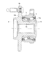
この発明の第1の実施形態を図1ないし図3と共に説明する。この実施形態は、第2世代型の内輪回転タイプで、例えばトラックやSUV等の比較的車体重量が大きい車両の車輪用軸受装置に適用したものである。なお、この明細書において、車両に取付けた状態で車両の車幅方向の外側寄りとなる側をアウトボード側と呼び、車両の中央寄りとなる側をインボード側と呼ぶ。 A first embodiment of the present invention will be described with reference to FIGS. This embodiment is a second generation inner ring rotating type, and is applied to a wheel bearing device for a vehicle having a relatively large vehicle body weight, such as a truck or SUV. In this specification, the side closer to the outer side in the vehicle width direction of the vehicle when attached to the vehicle is referred to as the outboard side, and the side closer to the center of the vehicle is referred to as the inboard side.
この車輪用軸受装置は、内周に複列の軌道面3を有する外方部材1と、外周に前記軌道面3に対向する複列の軌道面4を有する内方部材2と、これら外方部材1および内方部材2の軌道面3,4間に介在する複列の円すいころ5からなる転動体とでなり、複列円すいころ軸受型とされている。複列の円すいころ5は、互いに小径端が対向するように配置され、各列毎に保持器6で保持されている。外方部材1と内方部材2との間の軸受空間の両端はシール部材7により密封されている。
This wheel bearing device includes an outer member 1 having a double-
外方部材1は固定側の部材となるものであって、車体の懸架装置(図示せず)におけるナックルに取付けるフランジ1aを外周に有し、全体が一体の部品とされている。
内方部材2は回転側の部材となるものであって、筒状をした軸部9aのアウトボード側端外周に車輪取付用のハブフランジ9bが設けられたハブ輪9と、このハブ輪9の軸部9aの外周に嵌合する互いに軸方向に並んだ一対の内輪10とでなる。これら一対の内輪10の外周に、前記複列の軌道面4が形成されている。ハブ輪9は中心に、等速自在継手(図示せず)のステム部が挿通される貫通孔11を有する。内輪10は、大径端に大鍔10aを有し、小径端に小鍔10bを有する。大鍔10aの内面12は、円すいころ5の大径側の端面に接している。
The outer member 1 is a member on the fixed side, and has a
The
一対の内輪10は、ハブ輪軸部9aの外周に形成された内輪嵌合面13に圧入により組み込まれ、ハブフランジ9bの根元部とハブ輪9のインボード側端に設けた鍔状の加締部9cとで幅締めされてハブ輪9に固定される。図3に示すように、前記加締部9cの加締加工前はハブ輪9の端部に突出させた円筒状部9dとされていて、この円筒状部9dを外径側に加締めることにより、図1および図2に示す形状の加締部9cとなる。インボード側の内輪10の軸受外向きの端面14と内周面との間には、面取部15が設けられており、この面取部15に沿って加締部9cが加締められる。面取部15の断面形状は、外形が直線で表示される形状としてもよく、円弧等の曲線で表示される形状としてもよく、また直線と曲線を組み合わせて表示される形状としてもよい。
The pair of
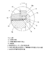
ハブ輪9は、内輪嵌合面13からハブフランジ9bの根元部にわたる表層部分に所定深さの熱処理層16が設けられている。この熱処理層16は、例えば高周波処理による硬化処理層とする。図2の部分拡大図に示すように、熱処理層16のインボード側の端部位置Aは、(1)インボード側内輪10の大鍔10aの内面12の延長面とハブ輪軸部9aの外径面とが交わる線Bよりはインボード側とし、かつ前記面取部15の内輪内径面側の縁Cよりはアウトボード側としている。また、熱処理層16のインボード側の端部位置Aは、(2)インボード側内輪10のインボード側端面14から8mm以下としている。熱処理層16のインボード側の端部位置Aは、上記(1)(2)の両方の条件を満たす範囲とする。この実施形態の場合、線Bが軸受外向きの端面14から8mm以下の位置に存在するため、熱処理層16のインボード側の端部位置Aは、B−Cの範囲(図2で矢印で示す範囲)内とする。
なお、内輪10は、表面から芯部までの全体か、また表面のみが焼入れ処理により硬化させてある。
The
In addition, the inner ring |
この構成の車輪用軸受装置によると、ハブ輪9における内輪嵌合面13からハブフランジ9bの根元部にわたる表層部分に熱処理層16が設けられているため、ハブフランジ9bの剛性が向上し、車両旋回時のハブフランジ9bの変形量が低下する。そのため、車輪回りの剛性の向上となる。熱処理層16は内輪嵌合面13に渡って設けられているため、耐クリープ性が向上する。
According to the wheel bearing device of this configuration, since the
ハブ輪9の熱処理層16は、そのインボード側の端部位置Aが、インボード側内輪10の大鍔10aの内面12の延長面とハブ輪軸部9aの外径面とが交わる線Bよりはインボード側とされているため、軸受装置にかかる曲げモーメントに起因してインボード側内輪10の大鍔10aが受ける力に対するハブ輪軸部9aの剛性および強度が向上する。このため、非熱処理では塑性変形するほどの荷重やモーメントが負荷された場合でも、ハブ輪軸部9aの塑性変形が生じない。
また、熱処理層16のインボード側の端部位置Aが、面取部15の内輪内径面側の縁Cよりはアウトボード側であるため、加締部9cを面取部15に沿って塑性変形させることが容易であり、かつこの加締加工により熱処理層16にクラックが生じることを防ぐことができる。
また、熱処理層16のインボード側の端部位置は、インボード側の軌道面4を有する内輪10の軸受外向きの端面14から8mm以下であり、熱処理層16が前記端面14の近くまで設けられているため、加締加工による内輪10の内輪嵌合面13での拡径量を小さくできると共に、拡径部分の開始位置を加締部9c側に近づけることができる。その結果、加締加工に伴う内輪10の変形および内輪軌道面4の変形を抑えることがで、長寿命化が可能となる
The
Further, since the end position A on the inboard side of the
Further, the end position on the inboard side of the
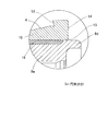
図4はこの発明の異なる実施形態を示す。この実施形態の車輪用軸受装置は、第3世代型であり、前記実施形態におけるアウトボード側の内輪10がハブ輪9と一体化されたものとされている。したがって、内方部材2の複列の軌道面4は、ハブ輪9および内輪10の内周に形成されている。内輪10は、ハブ輪軸部9aにおける軸方向のほぼ中心よりもインボード側の外周に形成された内輪嵌合面13に圧入により組み込まれ、内輪嵌合面13の段面13aとハブ輪9のインボード側端に設けた鍔状の加締部9cとで幅締めされてハブ輪9に固定される。外方部材1と内方部材2との間の軸受空間の両端は、シール部材7,8により密封されている。
FIG. 4 shows a different embodiment of the invention. The wheel bearing device of this embodiment is a third generation type, and the
ハブ輪9の熱処理層16は、内輪嵌合面13から、内輪嵌合面13の段面13aおよびアウトボード側の軌道面4を経てハブフランジ9bの根元部にわたる表層部分に設けられている。この実施形態の場合も、前記同様に、熱処理層16のインボード側の端部位置Aは、(1)インボード側内輪10の大鍔10aの内面12の延長面とハブ輪軸部9aの外径面とが交わる線Bよりはインボード側とし、かつ前記面取部15の内輪内径面側の縁Cよりはアウトボード側とし、また、(2)インボード側内輪10の軸受外向きの端面14から8mm以下とする(図2参照)。このようにハブ輪9に熱処理層16を設けることにより、前記実施形態の場合と同様の作用効果が得られる。
The
なお、上記各実施形態は、ハブ輪9の中心に等速自在継手のステム部が挿通される貫通孔11を有する駆動輪用の車輪用軸受装置を示しているが、この発明は、ハブ輪9が貫通孔11が無く中実である従動輪用の車輪用軸受装置にも適用することができる。
Each of the above embodiments shows a wheel bearing device for a drive wheel having a through
1…外方部材
2…内方部材
3,4…軌道面
5…円すいころ(転動体)
9…ハブ輪
9a…ハブ輪軸部
9b…ハブフランジ
9c…加締部
9d…円筒状部
10…内輪
10a…大鍔
12…大鍔の内面
13…内輪嵌合面
14…内輪の軸受外向きの端面
15…面取部
16…熱処理層
A…熱処理層のインボード側の端部位置
B…内輪大鍔内面の延長面とハブ輪軸部の外径面とが交わる線
C…面取部の内輪内径面側の縁
DESCRIPTION OF SYMBOLS 1 ...
DESCRIPTION OF
Claims (3)
前記ハブ輪における前記内輪嵌合面から前記ハブフランジの根元部にわたる表層部分に熱処理層が設けられ、この熱処理層のインボード側の端部位置Aを、前記内輪大鍔内面の延長面と前記ハブ輪軸部の外径面とが交わる線Bよりはインボード側とし、かつ前記面取部の内輪内径面側の縁Cよりはアウトボード側としたことを特徴とする車輪用軸受装置。 An outer member having a double-row raceway surface on the inner periphery and attached to the vehicle body, and a double-row raceway surface facing the raceway surface on the outer periphery and a hub flange for wheel mounting on the outer periphery of the outboard side end An inner member having a plurality of rolling elements interposed between the outer member and the raceway surface of the inner member, the inner member having a shaft portion and a hub wheel having the hub flange, and the hub The inner ring or the two inner rings each having an inboard side and an outboard side raceway surface, and the rolling elements are tapered rollers. , and the inner ring having a raceway surface of the inboard side has a large flange on the inboard end, the inner surface of the large flange is in contact with the end surface of the large diameter side of the tapered rollers, or one bearing outwardly This has a chamfered portion between the end face and the inner diameter face. Wheel is fixed to the wheel hub by a flange-like caulking portion Shimete become pressurized to the outer diameter side of the cylindrical portion which projects into an end portion of the hub wheel, the caulking portion along the chamfered portion In a double row tapered roller bearing type wheel bearing device to be crimped,
The heat treatment layer on the surface layer portion is provided from the inner ring fitting surface over the root portion of the hub flange, the end portion location A on the inboard side of the heat treatment layer, wherein the extended surface of the inner ring large rib inner surface of the hub wheel Ri by line B of the outer diameter surface of the hub wheel shaft portion intersects is the inboard side, and the Ri by edge C of the inner ring inner diameter side of the chamfer wheel bearing device is characterized in that the outboard side .
Priority Applications (5)
| Application Number | Priority Date | Filing Date | Title |
|---|---|---|---|
| JP2006167875A JP4986512B2 (en) | 2006-06-16 | 2006-06-16 | Wheel bearing device |
| PCT/JP2007/000427 WO2007125646A1 (en) | 2006-04-25 | 2007-04-19 | Bearing device for wheel |
| CN2007800149669A CN101432540B (en) | 2006-04-25 | 2007-04-19 | Bearing device for wheel |
| DE112007001017.7T DE112007001017B4 (en) | 2006-04-25 | 2007-04-19 | wheel bearing device |
| US12/254,913 US7618196B2 (en) | 2006-04-25 | 2008-10-21 | Wheel bearing apparatus |
Applications Claiming Priority (1)
| Application Number | Priority Date | Filing Date | Title |
|---|---|---|---|
| JP2006167875A JP4986512B2 (en) | 2006-06-16 | 2006-06-16 | Wheel bearing device |
Publications (2)
| Publication Number | Publication Date |
|---|---|
| JP2007333159A JP2007333159A (en) | 2007-12-27 |
| JP4986512B2 true JP4986512B2 (en) | 2012-07-25 |
Family
ID=38932811
Family Applications (1)
| Application Number | Title | Priority Date | Filing Date |
|---|---|---|---|
| JP2006167875A Active JP4986512B2 (en) | 2006-04-25 | 2006-06-16 | Wheel bearing device |
Country Status (1)
| Country | Link |
|---|---|
| JP (1) | JP4986512B2 (en) |
Families Citing this family (1)
| Publication number | Priority date | Publication date | Assignee | Title |
|---|---|---|---|---|
| CN205780287U (en) * | 2015-10-23 | 2016-12-07 | 日本精工株式会社 | Wheel support multiple row roller bearing unit |
Family Cites Families (3)
| Publication number | Priority date | Publication date | Assignee | Title |
|---|---|---|---|---|
| JP4015361B2 (en) * | 2000-08-24 | 2007-11-28 | Ntn株式会社 | Wheel bearing device |
| JP2005195168A (en) * | 2003-12-10 | 2005-07-21 | Ntn Corp | Bearing for wheel and semi-floating type bearing unit equipped with the same |
| JP2006076346A (en) * | 2004-09-07 | 2006-03-23 | Ntn Corp | Bearing device for wheel |
-
2006
- 2006-06-16 JP JP2006167875A patent/JP4986512B2/en active Active
Also Published As
| Publication number | Publication date |
|---|---|
| JP2007333159A (en) | 2007-12-27 |
Similar Documents
| Publication | Publication Date | Title |
|---|---|---|
| JP5079270B2 (en) | Wheel bearing unit | |
| JP2002250358A (en) | Rolling bearing unit for supporting wheel | |
| JP2008175262A (en) | Wheel bearing device and its manufacturing method | |
| JP2001018605A (en) | Bearing device for driving wheel | |
| JP4519003B2 (en) | Wheel bearing device | |
| JP4606883B2 (en) | Wheel bearing device | |
| US8142081B2 (en) | Wheel support bearing assembly | |
| JP4986512B2 (en) | Wheel bearing device | |
| JP2008173995A (en) | Bearing device for wheel | |
| JP4519004B2 (en) | Wheel bearing device | |
| JP4562461B2 (en) | Wheel bearing device | |
| JP3902392B2 (en) | Drive wheel bearing device | |
| JP2013092246A (en) | Wheel bearing device | |
| JP2008247274A (en) | Wheel bearing device | |
| JP2009156450A (en) | Bearing device for wheel | |
| JP2006336761A (en) | Bearing device for wheel | |
| JP2006076346A (en) | Bearing device for wheel | |
| JP5150990B2 (en) | Manufacturing method of axle bearing device | |
| JP4553676B2 (en) | Wheel bearing device | |
| JP4467481B2 (en) | Wheel bearing device | |
| JP5143442B2 (en) | Drive wheel bearing device | |
| JP2008057717A (en) | Bearing device for wheel | |
| JP2007024132A (en) | Wheel bearing device and its caulking method | |
| JP5283315B2 (en) | Wheel bearing device | |
| JP3902391B2 (en) | Drive wheel bearing device |
Legal Events
| Date | Code | Title | Description |
|---|---|---|---|
| A621 | Written request for application examination |
Free format text: JAPANESE INTERMEDIATE CODE: A621 Effective date: 20090319 |
|
| A131 | Notification of reasons for refusal |
Free format text: JAPANESE INTERMEDIATE CODE: A131 Effective date: 20111115 |
|
| A521 | Request for written amendment filed |
Free format text: JAPANESE INTERMEDIATE CODE: A523 Effective date: 20120112 |
|
| TRDD | Decision of grant or rejection written | ||
| A01 | Written decision to grant a patent or to grant a registration (utility model) |
Free format text: JAPANESE INTERMEDIATE CODE: A01 Effective date: 20120424 |
|
| A01 | Written decision to grant a patent or to grant a registration (utility model) |
Free format text: JAPANESE INTERMEDIATE CODE: A01 |
|
| A61 | First payment of annual fees (during grant procedure) |
Free format text: JAPANESE INTERMEDIATE CODE: A61 Effective date: 20120424 |
|
| R150 | Certificate of patent or registration of utility model |
Ref document number: 4986512 Country of ref document: JP Free format text: JAPANESE INTERMEDIATE CODE: R150 Free format text: JAPANESE INTERMEDIATE CODE: R150 |
|
| FPAY | Renewal fee payment (event date is renewal date of database) |
Free format text: PAYMENT UNTIL: 20150511 Year of fee payment: 3 |
|
| R250 | Receipt of annual fees |
Free format text: JAPANESE INTERMEDIATE CODE: R250 |
|
| R250 | Receipt of annual fees |
Free format text: JAPANESE INTERMEDIATE CODE: R250 |
|
| R250 | Receipt of annual fees |
Free format text: JAPANESE INTERMEDIATE CODE: R250 |
|
| R250 | Receipt of annual fees |
Free format text: JAPANESE INTERMEDIATE CODE: R250 |
|
| R250 | Receipt of annual fees |
Free format text: JAPANESE INTERMEDIATE CODE: R250 |
|
| R250 | Receipt of annual fees |
Free format text: JAPANESE INTERMEDIATE CODE: R250 |
|
| R250 | Receipt of annual fees |
Free format text: JAPANESE INTERMEDIATE CODE: R250 |
|
| R250 | Receipt of annual fees |
Free format text: JAPANESE INTERMEDIATE CODE: R250 |
|
| R250 | Receipt of annual fees |
Free format text: JAPANESE INTERMEDIATE CODE: R250 |