EP1921032B1 - Vorrichtung für den Transport von Schüttgut - Google Patents
Vorrichtung für den Transport von Schüttgut Download PDFInfo
- Publication number
- EP1921032B1 EP1921032B1 EP06123643A EP06123643A EP1921032B1 EP 1921032 B1 EP1921032 B1 EP 1921032B1 EP 06123643 A EP06123643 A EP 06123643A EP 06123643 A EP06123643 A EP 06123643A EP 1921032 B1 EP1921032 B1 EP 1921032B1
- Authority
- EP
- European Patent Office
- Prior art keywords
- pneumatic
- compressed air
- bulk material
- pressure
- connection
- Prior art date
- Legal status (The legal status is an assumption and is not a legal conclusion. Google has not performed a legal analysis and makes no representation as to the accuracy of the status listed.)
- Not-in-force
Links
- 239000013590 bulk material Substances 0.000 title claims abstract description 47
- 230000000712 assembly Effects 0.000 description 4
- 238000000429 assembly Methods 0.000 description 4
- 239000000463 material Substances 0.000 description 4
- 238000010276 construction Methods 0.000 description 2
- 238000005265 energy consumption Methods 0.000 description 2
- 238000012423 maintenance Methods 0.000 description 2
- 238000005299 abrasion Methods 0.000 description 1
- 230000002950 deficient Effects 0.000 description 1
- 230000001419 dependent effect Effects 0.000 description 1
- 230000008021 deposition Effects 0.000 description 1
- 239000002184 metal Substances 0.000 description 1
- 239000000203 mixture Substances 0.000 description 1
- 230000003068 static effect Effects 0.000 description 1
Images


Classifications
-
- B—PERFORMING OPERATIONS; TRANSPORTING
- B65—CONVEYING; PACKING; STORING; HANDLING THIN OR FILAMENTARY MATERIAL
- B65G—TRANSPORT OR STORAGE DEVICES, e.g. CONVEYORS FOR LOADING OR TIPPING, SHOP CONVEYOR SYSTEMS OR PNEUMATIC TUBE CONVEYORS
- B65G53/00—Conveying materials in bulk through troughs, pipes or tubes by floating the materials or by flow of gas, liquid or foam
- B65G53/04—Conveying materials in bulk pneumatically through pipes or tubes; Air slides
- B65G53/28—Systems utilising a combination of gas pressure and suction
-
- B—PERFORMING OPERATIONS; TRANSPORTING
- B65—CONVEYING; PACKING; STORING; HANDLING THIN OR FILAMENTARY MATERIAL
- B65G—TRANSPORT OR STORAGE DEVICES, e.g. CONVEYORS FOR LOADING OR TIPPING, SHOP CONVEYOR SYSTEMS OR PNEUMATIC TUBE CONVEYORS
- B65G53/00—Conveying materials in bulk through troughs, pipes or tubes by floating the materials or by flow of gas, liquid or foam
- B65G53/04—Conveying materials in bulk pneumatically through pipes or tubes; Air slides
- B65G53/06—Gas pressure systems operating without fluidisation of the materials
- B65G53/10—Gas pressure systems operating without fluidisation of the materials with pneumatic injection of the materials by the propelling gas
- B65G53/12—Gas pressure systems operating without fluidisation of the materials with pneumatic injection of the materials by the propelling gas the gas flow acting directly on the materials in a reservoir
Definitions
- the invention relates to a device for the transport of bulk material from a pressure silo, according to the preamble of claim 1.
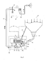
- FIG. 1 shows such a device known from the prior art.
- the first unit 20 consists of a pinch valve 22 and a first pneumatic compressor 21, wherein the first pneumatic compressor 21 is used to control the pinch valve 22.
- the pinch valve 22 is closed so that the pneumatic transport of bulk material from the pressure silo 10 to a consumer 50 is interrupted.
- the second unit 30 of the device known from the prior art has a second pneumatic compressor 31 and a control cabinet 32.
- the second pneumatic compressor 31 By means of the second pneumatic compressor 31 is a pipe union 23, which is arranged in the first unit 20, acted upon with compressed air.
- the second air compressor 31 is connected via a pipe 40 to the pipe union 23.
- the pressurization of the pipe union 23 with compressed air from the second air compressor 31 causes a floating onward transport of the bulk material from the pressure silo 10 of the pipe union 23 to the bulk consumer 50th
- hose connection 27 it is known from the prior art to connect the second compressed air compressor 31 with the compressed air silo 10 via a hose connection 27 to pressurize the pressure silo 10 with compressed air for the purpose of establishing or maintaining a constant pressure in the pressure silo 10.
- the length of the hose connection 27 is dependent on the distance of the second unit 30 from the location of the pressure silo 10th
- the arranged on the second unit 30 cabinet 32 is used to control both the second air compressor 31 and the first pneumatic compressor 21. Furthermore, the cabinet 32 is also connected to a level sensor 51, which is arranged on a bulk consumer 50. If a corresponding level is reached in the bulk consumer 50, controls the control cabinet 32, the second air compressor 31 and the first air compressor 21 by the first air compressor 21 is caused to pressurize the pinch valve 22, and the second air compressor 31 is caused, the admission of the Pipe union 22 with compressed air to interrupt.
- the two units 20 and 30 must be delivered separately when commissioning a pressure silo on a construction site. After attaching the unit 20 at the outlet of the pressure silo 10, the unit 30 must be connected via an additional pipeline to the pipe union 23 of the unit 20. About another pipeline, which in Fig. 1 not shown, the unit 30 is also connected to the pressure silo 10 to produce 10 pressure in the pressure silo. Furthermore, two power cables for the power supply of the compressor 21 and the solenoid valve on the pinch valve 22 is needed. These power cables are exposed between unit 20 and unit 30. This has the disadvantage that the unit 30 must be arranged at the construction site in the vicinity of the pressure silo 10 that a connection by means of a pipe 40 and the power cable of the unit 20 with the unit 30 is possible.
- Another disadvantage is that for the purpose of anti-theft both units 20 and 30 must be secured separately. Another disadvantage is that two compressed air sources are necessary to operate the device. This increases both the maintenance and the energy consumption of the device known from the prior art. Another device for the pneumatic transport of bulk material is out EP-A-0 867 389 known.
- Object of the present invention is therefore to provide a device for the pneumatic transport of bulk material from pressure silos, which avoids the disadvantages mentioned at least partially.
- a device for the pneumatic transport of bulk material from a pressure silo according to claim 1 is provided.
- the device according to the invention can also be extended for the operation of several pressure silos. This can be dispensed with additional air compressors for the respective pinch valves, since the one air pressure compressor according to the invention is able to supply all these pinch valves with compressed air.
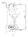
- Fig. 2 shows an embodiment of the device 70 according to the invention for the transport of bulk material from pressure silos.
- the device 70 includes in Essentially a compressed air compressor 71, a pipe union 23 and a pneumatic shut-off device 22.
- the pneumatic shut-off device 22 can be configured as a pinch valve, which can be closed by applying compressed air.
- the inlet 25b of the pipe union 23 is connected to the compressed air compressor 71 via a pipe segment 23a.
- the pipe segment 23a can also be formed as a hose connection.
- the inlet 25 a of the pipe union 23 is connected to the outlet 24 a of the pinch valve 22. In this case, the input 25a can be connected directly to the output 24a or via a corresponding pipe segment.
- the pinch valve 22 is connected via a pipe segment 22 a with the compressed air compressor 71. Furthermore, the pressure silo 10 can also be connected to the compressed air compressor 71 via a pipe or hose connection.
- the air compressor 71 is used to pressurize both the pipe union 23, the pinch valve 22 and the pressure silo 10 with compressed air.
- the control of the application of compressed air of the pipe union 23, the pinch valve 22 and the pressure silo 10 is in this case taken over by a control device 72.
- the control device 72 can also be designed as a control device.
- the control device 72 ensures that the pressure silo 10 has a constant pressure, that the pinch valve 22 is closed when no bulk material from the pressure silo 10 is needed, and that the pipe union 23 is subjected to sufficient compressed air, so that a floating onward transport of the bulk material from the pipe union 23 to the bulk consumer 50 is ensured.
- the air compressor 71, the controller 72, the pinch valve 22 and the pipe union 23 are housed in a housing.
- the pinch valve 22 is on the input side 24b via a pipe segment 42 or over a kink-resistant and abrasion-resistant hose, which preferably has a jacket with a metal spiral, connected to the output 11 of the pressure silo 10.
- the tube segment or kink resistant tube 42 has a length of about 0.8 to 1 m and a diameter of about 50 mm. To the inlet 24b of the pinch valve 22 towards the diameter of the pipe segment or the kink resistant hose 42 increases to about 65 mm. These dimensions ensure optimum flow of the bulk material from the pressure silo 10 to the pinch valve 22.
- the pipe segment or the kink-resistant hose 42 may be configured longer or shorter or with a larger or smaller diameter.
- the pressure generated by the compressed air compressor 71 in the pressure silo 10 and by means of the autogenous pressure of the bulk material located in the pressure bulk material 10 the bulk material passes automatically from the outlet 11 of the pressure silo 10 to the outlet of the pipe union 23.
- the material flow of the bulk material from the outlet 11 of the pressure silo 10 to to the outlet 25 of the pipe union 23 can be interrupted by the pneumatic pinch valve 22 by this is closed.
- the pinch valve 22 is arranged with an inclination of about 45 ° to the output 11 of the pressure silo 10, so as to allow the best possible flow of material through the pipe or the hose 42.
- a horizontal arrangement of the pinch valve 22 with respect to the output 11 of the silo 10 is also feasible - the pressure in the pressure silo 10, however, must be increased here.
- the pinch valve 22 of about 45 °, it is sufficient to keep the air pressure in the pressure silo 10 to about 2 bar constant.
- the pipe or the hose 42 has a strong kink, which leads to increased friction losses of the bulk material at the bend in the pipe or the hose 42.
- the outlet 25 of the pipe union 23 is connected via a hose connection 41 with a bulk consumer 50, such as a plastering machine with level indicator.
- a bulk consumer 50 such as a plastering machine with level indicator.
- the bulk material passes from the outlet 11 of the pressure silo via the pipe connection 42 to the pinch valve 22 and from there to the pipe union 23.
- the pressurized air at the pipe union 23 ensures the floating onward transport of the bulk material to the bulk consumer 50. If bulk material is no longer needed at the bulk consumer 50, which can be determined by a level indicator 51, for example, the cabinet 72 ensures that the pinch valve 22 is acted upon by a compressed air compressor 71 via a pipe union 22a, so that the pinch valve closes. If the pressurization of the pinch valve 22 is stopped with compressed air, the pinch valve opens again and the bulk material available at the inlet 24b of the pinch valve is again transported via the pipe union 23 by means of compressed air to the bulk material consumer 50.
- the device 70 has an additional compressed air chamber 26, which is also connected via a pipe connection 26 a with the compressed air compressor 71.
- the compressed air chamber 26 is connected via a pipe segment 26b to the pipe segment 22a which connects the pinch valve 22 to the compressed air compressor 71.
- the compressed air chamber 26 is acted upon by compressed air from the compressed air compressor, wherein preferably a pressure of about 3 bar in the compressed air chamber 26 is generated.
- the pipe segments 26a and 26b each have a check valve so that the compressed air contained in the compressed air chamber 26 can not escape.
- the pressure in the compressed air chamber 26 is to be chosen so that the pressure is sufficient to close the pinch valve 22 in an emergency can still.
- the check valve opens in the pipe segment 26b, whereby the pinch valve 22 is acted upon with compressed air from the compressed air chamber 26.
- the check valve in the tube segment 26a prevents escape of compressed air from the compressed air chamber 26, so that the pinch valve 22 remains permanently closed.
- the housing of the device 70 may be formed as a tubular frame, wherein the tube frame simultaneously forms the compressed air chamber 26.
- the device 70 is now a unit, which allows for a simpler anti-theft device and on the other hand a simpler handling during transport and use at the respective site.
- the air compressor 21 via an electrical line 60a from the control unit 32, which is located in the unit 30, controlled.
- the device 70 by means of a suitable arrangement of the pinch valve 22, the device 70 can be connected directly to the outlet 11 of the pressure silo 10 so that the pipeline or the hose connection 42 as well as the above-mentioned power lines can be dispensed with.
- the device 70 according to the invention can thus be dispensed with a second pneumatic compressor 21, a pipe 40 and a control cable 60a, which leads to a better handling of the device 70, to a lower energy consumption and lower production costs.
- Fig. 3 shows the device according to the invention with an alternative arrangement of the pinch valve 22 on the air compressor 71.
- the pinch valve 22 is also connected to the input 24b by means of a pipe or hose connection 42 to the output 11 of the pressure silo 10.
- pipe union 23 is not applied laterally with compressed air but via the input 23a from the rear. Again, the application of compressed air of the pipe union 23 causes a floating onward transport of the bulk material from the outlet 25 of the pipe union 23 to the bulk consumer 50.
- the arrangement shown can be dispensed on the known from the prior art second air compressor 21 and the additional pipe or hose connection 40.
- Fig. 4 shows an inventive development of the device for the pneumatic transport of bulk material from a plurality of pressure silos.
- the device 70 in this case includes a plurality of pinch valves 22 and a plurality of connected tube assemblies 23.
- the output 25 of the first pipe union 23 is connected to the inlet 25a of the next pipe union 23 via a pipe or hose segment.
- each pinch valve 22 is associated with an additional compressed air chamber 26, which, as already in Fig. 2 described causes a closing of the respective pinch valve 22 in the event of failure of the air compressor 71.
- a common compressed air chamber 26 can be provided for all pinch valves 22, wherein attention must be paid to a corresponding overpressure in the common pressure chamber 26, so that closing of all connected pinch valves 22 via the compressed air from the common compressed air chamber 26 is possible.
- the first pipe union 23 is connected to the inlet 25a with a pipe or a hose 23a with the compressed air compressor 71.
- the respectively supplied to the individual pipe assemblies material from the pressure silo 10 is transported by means of the supplied compressed air floating to the bulk consumer.
- the control device 72 ensures that the pinch valves are acted upon in accordance with certain specifications with compressed air from the compressor 71 and thus closed.
- the outputs 25 of the pipe assemblies 23 are each connected via a pipe or hose segment with individual bulk consumers.
- bulk material from different pressure silos can be supplied to different bulk material consumers.
- Fig. 1 shown from the prior art known devices can be dispensed with, since all the required pipe assemblies 23 and pinch valves 22 are arranged in the device 70 and only a common air compressor 71 is necessary.
- the device 70 according to the invention can be used in addition to a floating promotion of the bulk material by reducing the compressed air supply at the entrance 25b of the pipe union 23 also for a Strandsbid the bulk material.
- a strands promotion over static deposition and a plug conveying is possible.
Landscapes
- Engineering & Computer Science (AREA)
- Mechanical Engineering (AREA)
- Air Transport Of Granular Materials (AREA)
- Cyclones (AREA)
- Control And Other Processes For Unpacking Of Materials (AREA)
- Auxiliary Methods And Devices For Loading And Unloading (AREA)
Priority Applications (6)
| Application Number | Priority Date | Filing Date | Title |
|---|---|---|---|
| PT06123643T PT1921032E (pt) | 2006-11-07 | 2006-11-07 | Dispositivo para o transporte de produtos a granel |
| PL06123643T PL1921032T3 (pl) | 2006-11-07 | 2006-11-07 | Urządzenie do transportu materiału sypkiego |
| AT06123643T ATE446932T1 (de) | 2006-11-07 | 2006-11-07 | Vorrichtung für den transport von schüttgut |
| EP06123643A EP1921032B1 (de) | 2006-11-07 | 2006-11-07 | Vorrichtung für den Transport von Schüttgut |
| ES06123643T ES2333459T3 (es) | 2006-11-07 | 2006-11-07 | Dispositivo para el transporte de materiales a granel. |
| DE502006005263T DE502006005263D1 (de) | 2006-11-07 | 2006-11-07 | Vorrichtung für den Transport von Schüttgut |
Applications Claiming Priority (1)
| Application Number | Priority Date | Filing Date | Title |
|---|---|---|---|
| EP06123643A EP1921032B1 (de) | 2006-11-07 | 2006-11-07 | Vorrichtung für den Transport von Schüttgut |
Publications (2)
| Publication Number | Publication Date |
|---|---|
| EP1921032A1 EP1921032A1 (de) | 2008-05-14 |
| EP1921032B1 true EP1921032B1 (de) | 2009-10-28 |
Family
ID=37895969
Family Applications (1)
| Application Number | Title | Priority Date | Filing Date |
|---|---|---|---|
| EP06123643A Not-in-force EP1921032B1 (de) | 2006-11-07 | 2006-11-07 | Vorrichtung für den Transport von Schüttgut |
Country Status (6)
| Country | Link |
|---|---|
| EP (1) | EP1921032B1 (pl) |
| AT (1) | ATE446932T1 (pl) |
| DE (1) | DE502006005263D1 (pl) |
| ES (1) | ES2333459T3 (pl) |
| PL (1) | PL1921032T3 (pl) |
| PT (1) | PT1921032E (pl) |
Families Citing this family (3)
| Publication number | Priority date | Publication date | Assignee | Title |
|---|---|---|---|---|
| DE102015117072A1 (de) * | 2015-10-07 | 2017-04-13 | M-Tec Mathis Technik Gmbh | Fördervorrichtung und Verfahren zur Förderung eines in einem Silo vorgehaltenen Mediums |
| CN113041900A (zh) * | 2021-03-24 | 2021-06-29 | 上海智质科技有限公司 | 一种物料自动发送用物料均化装置 |
| CN118753810B (zh) * | 2024-09-04 | 2024-11-29 | 江苏新业重工股份有限公司 | 一种用于水泥加工供料输送装置 |
Family Cites Families (4)
| Publication number | Priority date | Publication date | Assignee | Title |
|---|---|---|---|---|
| DE2912794C2 (de) * | 1979-03-30 | 1983-12-01 | Perlite-Dämmstoff-GmbH & Co, Beratung und Vertrieb, 4600 Dortmund | Vorrichtung zum Einbringen von körnigen Wärmedämmstoffen |
| US5033914A (en) * | 1989-09-29 | 1991-07-23 | Cyclonaire Corporation | High efficiency feeder apparatus for pneumatic conveying lines |
| DE59809892D1 (de) * | 1997-03-19 | 2003-11-20 | Mai Internat Gmbh Feistritz | Fördereinrichtung und Verfahren zum Fördern von pulverförmigem oder körnigem Material |
| DE19935727C2 (de) * | 1999-07-29 | 2002-05-16 | Klein Anlagenbau Ag | Vorrichtung und Verfahren zum Einbringen von Schüttgut in einen Verbraucher |
-
2006
- 2006-11-07 PL PL06123643T patent/PL1921032T3/pl unknown
- 2006-11-07 ES ES06123643T patent/ES2333459T3/es active Active
- 2006-11-07 PT PT06123643T patent/PT1921032E/pt unknown
- 2006-11-07 DE DE502006005263T patent/DE502006005263D1/de active Active
- 2006-11-07 AT AT06123643T patent/ATE446932T1/de active
- 2006-11-07 EP EP06123643A patent/EP1921032B1/de not_active Not-in-force
Also Published As
| Publication number | Publication date |
|---|---|
| PT1921032E (pt) | 2010-02-03 |
| EP1921032A1 (de) | 2008-05-14 |
| ES2333459T3 (es) | 2010-02-22 |
| DE502006005263D1 (de) | 2009-12-10 |
| PL1921032T3 (pl) | 2010-03-31 |
| ATE446932T1 (de) | 2009-11-15 |
Similar Documents
| Publication | Publication Date | Title |
|---|---|---|
| DE102015009013A1 (de) | Gasleitungsentleerungssystem und -verfahren | |
| AT516916A2 (de) | Pneumatische Förderereinrichtung und Dosieranlage sowie Sandungsanlage mit einer Strahlpumpe für rieselfähiges Gut | |
| EP3768563B1 (de) | Vorrichtung zum streuen von granulat | |
| EP2767353A1 (de) | Kühlstrecke mit Power Cooling und Laminarkühlung | |
| EP2258450B1 (de) | Neuartige Schlauchaufrollvorrichtung | |
| EP1921032B1 (de) | Vorrichtung für den Transport von Schüttgut | |
| DE3224710C2 (de) | Schneckenpumpe mit an beiden Enden gelagerter Schnecke | |
| DE3444816A1 (de) | Pneumatische foerdervorrichtung | |
| DE1938837A1 (de) | Transportvorrichtung | |
| AT411338B (de) | Vorrichtung sowie verfahren zum fehlererkennen bei der schweissdrahtförderung | |
| EP1730059B1 (de) | Vorrichtung und verfahren zur pneumatischen förderung von fe inteiligen schü ttgütern | |
| DE20103682U1 (de) | Gasbündelstation mit Druckmindererstation und Sicherheitsabschaltung | |
| DE2435625C3 (de) | Rohrleitungssystem zur pneumatischen Förderung von Schutt- oder Mahlgut | |
| EP0607853B1 (de) | Flockierwalzwerk mit einer Produktführung je an den axialen Enden der Walzen | |
| DE102012201455A1 (de) | Weiche für pneumatische Förderanlage | |
| DE102018110013A1 (de) | Vorrichtung und Verfahren zum Ausscheiden von Metallpartikeln | |
| EP0118697B1 (de) | Vorrichtung zum Einschleusen von staubförmigem Fördergut, insbesondere Zement und Zementrohmehl | |
| DE19503413C2 (de) | Vorrichtung zum Einbringen von Schüttgut in eine Förderleitung | |
| DE2456476B1 (de) | Vorrichtung zum kontinuierlichen foerdern von pulverfoermigem und griessigem schuettgut | |
| EP3993917B1 (de) | Kuehlstrecke mit ventilen und druckgefaessen zur vermeidung von druckschlaegen | |
| EP4151569B1 (de) | Absperrschieber mit bypassvorrichtung | |
| EP2428287A1 (de) | Vorrichtung und Verfahren zur Reinigung und/oder Belüftung eines Flüssigkeitsbehälters | |
| CH654551A5 (de) | Verfahren und vorrichtung zur steuerung der entnahme von schuettguetern aus druckbeaufschlagten behaeltern. | |
| DE69505110T2 (de) | Abdicht- und entspannungssystem einer flüssigkeitsversorgungsleitung | |
| DE3331414A1 (de) | Verfahren zur einbringung koerniger und/oder staubfoermiger gueter in pneumatische foerderanlagen und foerdervorrichtung zur durchfuehrung dieses verfahrens |
Legal Events
| Date | Code | Title | Description |
|---|---|---|---|
| PUAI | Public reference made under article 153(3) epc to a published international application that has entered the european phase |
Free format text: ORIGINAL CODE: 0009012 |
|
| AK | Designated contracting states |
Kind code of ref document: A1 Designated state(s): AT BE BG CH CY CZ DE DK EE ES FI FR GB GR HU IE IS IT LI LT LU LV MC NL PL PT RO SE SI SK TR |
|
| AX | Request for extension of the european patent |
Extension state: AL BA HR MK RS |
|
| 17P | Request for examination filed |
Effective date: 20080523 |
|
| AKX | Designation fees paid |
Designated state(s): AT BE BG CH CY CZ DE DK EE ES FI FR GB GR HU IE IS IT LI LT LU LV MC NL PL PT RO SE SI SK TR |
|
| GRAP | Despatch of communication of intention to grant a patent |
Free format text: ORIGINAL CODE: EPIDOSNIGR1 |
|
| GRAS | Grant fee paid |
Free format text: ORIGINAL CODE: EPIDOSNIGR3 |
|
| GRAA | (expected) grant |
Free format text: ORIGINAL CODE: 0009210 |
|
| AK | Designated contracting states |
Kind code of ref document: B1 Designated state(s): AT BE BG CH CY CZ DE DK EE ES FI FR GB GR HU IE IS IT LI LT LU LV MC NL PL PT RO SE SI SK TR |
|
| REG | Reference to a national code |
Ref country code: GB Ref legal event code: FG4D Free format text: NOT ENGLISH |
|
| REG | Reference to a national code |
Ref country code: CH Ref legal event code: EP |
|
| REG | Reference to a national code |
Ref country code: IE Ref legal event code: FG4D |
|
| REF | Corresponds to: |
Ref document number: 502006005263 Country of ref document: DE Date of ref document: 20091210 Kind code of ref document: P |
|
| PGFP | Annual fee paid to national office [announced via postgrant information from national office to epo] |
Ref country code: AT Payment date: 20091204 Year of fee payment: 4 |
|
| REG | Reference to a national code |
Ref country code: PT Ref legal event code: SC4A Free format text: AVAILABILITY OF NATIONAL TRANSLATION Effective date: 20100126 |
|
| REG | Reference to a national code |
Ref country code: ES Ref legal event code: FG2A Ref document number: 2333459 Country of ref document: ES Kind code of ref document: T3 |
|
| LTIE | Lt: invalidation of european patent or patent extension |
Effective date: 20091028 |
|
| REG | Reference to a national code |
Ref country code: PL Ref legal event code: T3 |
|
| NLV1 | Nl: lapsed or annulled due to failure to fulfill the requirements of art. 29p and 29m of the patents act | ||
| PG25 | Lapsed in a contracting state [announced via postgrant information from national office to epo] |
Ref country code: LT Free format text: LAPSE BECAUSE OF FAILURE TO SUBMIT A TRANSLATION OF THE DESCRIPTION OR TO PAY THE FEE WITHIN THE PRESCRIBED TIME-LIMIT Effective date: 20091028 Ref country code: IS Free format text: LAPSE BECAUSE OF FAILURE TO SUBMIT A TRANSLATION OF THE DESCRIPTION OR TO PAY THE FEE WITHIN THE PRESCRIBED TIME-LIMIT Effective date: 20100228 Ref country code: FI Free format text: LAPSE BECAUSE OF FAILURE TO SUBMIT A TRANSLATION OF THE DESCRIPTION OR TO PAY THE FEE WITHIN THE PRESCRIBED TIME-LIMIT Effective date: 20091028 Ref country code: SE Free format text: LAPSE BECAUSE OF FAILURE TO SUBMIT A TRANSLATION OF THE DESCRIPTION OR TO PAY THE FEE WITHIN THE PRESCRIBED TIME-LIMIT Effective date: 20091028 |
|
| REG | Reference to a national code |
Ref country code: IE Ref legal event code: FD4D |
|
| BERE | Be: lapsed |
Owner name: MORTEC-SYSTEM GMBH Effective date: 20091130 |
|
| PG25 | Lapsed in a contracting state [announced via postgrant information from national office to epo] |
Ref country code: LV Free format text: LAPSE BECAUSE OF FAILURE TO SUBMIT A TRANSLATION OF THE DESCRIPTION OR TO PAY THE FEE WITHIN THE PRESCRIBED TIME-LIMIT Effective date: 20091028 Ref country code: CY Free format text: LAPSE BECAUSE OF FAILURE TO SUBMIT A TRANSLATION OF THE DESCRIPTION OR TO PAY THE FEE WITHIN THE PRESCRIBED TIME-LIMIT Effective date: 20091028 Ref country code: SI Free format text: LAPSE BECAUSE OF FAILURE TO SUBMIT A TRANSLATION OF THE DESCRIPTION OR TO PAY THE FEE WITHIN THE PRESCRIBED TIME-LIMIT Effective date: 20091028 |
|
| PG25 | Lapsed in a contracting state [announced via postgrant information from national office to epo] |
Ref country code: MC Free format text: LAPSE BECAUSE OF NON-PAYMENT OF DUE FEES Effective date: 20091130 |
|
| PG25 | Lapsed in a contracting state [announced via postgrant information from national office to epo] |
Ref country code: DK Free format text: LAPSE BECAUSE OF FAILURE TO SUBMIT A TRANSLATION OF THE DESCRIPTION OR TO PAY THE FEE WITHIN THE PRESCRIBED TIME-LIMIT Effective date: 20091028 Ref country code: RO Free format text: LAPSE BECAUSE OF FAILURE TO SUBMIT A TRANSLATION OF THE DESCRIPTION OR TO PAY THE FEE WITHIN THE PRESCRIBED TIME-LIMIT Effective date: 20091028 Ref country code: EE Free format text: LAPSE BECAUSE OF FAILURE TO SUBMIT A TRANSLATION OF THE DESCRIPTION OR TO PAY THE FEE WITHIN THE PRESCRIBED TIME-LIMIT Effective date: 20091028 Ref country code: IE Free format text: LAPSE BECAUSE OF FAILURE TO SUBMIT A TRANSLATION OF THE DESCRIPTION OR TO PAY THE FEE WITHIN THE PRESCRIBED TIME-LIMIT Effective date: 20091028 Ref country code: BG Free format text: LAPSE BECAUSE OF FAILURE TO SUBMIT A TRANSLATION OF THE DESCRIPTION OR TO PAY THE FEE WITHIN THE PRESCRIBED TIME-LIMIT Effective date: 20100128 |
|
| PG25 | Lapsed in a contracting state [announced via postgrant information from national office to epo] |
Ref country code: CZ Free format text: LAPSE BECAUSE OF FAILURE TO SUBMIT A TRANSLATION OF THE DESCRIPTION OR TO PAY THE FEE WITHIN THE PRESCRIBED TIME-LIMIT Effective date: 20091028 Ref country code: SK Free format text: LAPSE BECAUSE OF FAILURE TO SUBMIT A TRANSLATION OF THE DESCRIPTION OR TO PAY THE FEE WITHIN THE PRESCRIBED TIME-LIMIT Effective date: 20091028 |
|
| PLBE | No opposition filed within time limit |
Free format text: ORIGINAL CODE: 0009261 |
|
| STAA | Information on the status of an ep patent application or granted ep patent |
Free format text: STATUS: NO OPPOSITION FILED WITHIN TIME LIMIT |
|
| 26N | No opposition filed |
Effective date: 20100729 |
|
| PG25 | Lapsed in a contracting state [announced via postgrant information from national office to epo] |
Ref country code: BE Free format text: LAPSE BECAUSE OF NON-PAYMENT OF DUE FEES Effective date: 20091130 Ref country code: GR Free format text: LAPSE BECAUSE OF FAILURE TO SUBMIT A TRANSLATION OF THE DESCRIPTION OR TO PAY THE FEE WITHIN THE PRESCRIBED TIME-LIMIT Effective date: 20100129 |
|
| PGFP | Annual fee paid to national office [announced via postgrant information from national office to epo] |
Ref country code: PL Payment date: 20101027 Year of fee payment: 5 |
|
| PGFP | Annual fee paid to national office [announced via postgrant information from national office to epo] |
Ref country code: IT Payment date: 20101124 Year of fee payment: 5 Ref country code: GB Payment date: 20101123 Year of fee payment: 5 |
|
| PG25 | Lapsed in a contracting state [announced via postgrant information from national office to epo] |
Ref country code: LU Free format text: LAPSE BECAUSE OF NON-PAYMENT OF DUE FEES Effective date: 20091107 |
|
| PG25 | Lapsed in a contracting state [announced via postgrant information from national office to epo] |
Ref country code: HU Free format text: LAPSE BECAUSE OF FAILURE TO SUBMIT A TRANSLATION OF THE DESCRIPTION OR TO PAY THE FEE WITHIN THE PRESCRIBED TIME-LIMIT Effective date: 20100429 |
|
| PG25 | Lapsed in a contracting state [announced via postgrant information from national office to epo] |
Ref country code: TR Free format text: LAPSE BECAUSE OF FAILURE TO SUBMIT A TRANSLATION OF THE DESCRIPTION OR TO PAY THE FEE WITHIN THE PRESCRIBED TIME-LIMIT Effective date: 20091028 |
|
| PGFP | Annual fee paid to national office [announced via postgrant information from national office to epo] |
Ref country code: ES Payment date: 20111123 Year of fee payment: 6 Ref country code: FR Payment date: 20111125 Year of fee payment: 6 Ref country code: CH Payment date: 20111124 Year of fee payment: 6 |
|
| PGFP | Annual fee paid to national office [announced via postgrant information from national office to epo] |
Ref country code: DE Payment date: 20120125 Year of fee payment: 6 |
|
| PG25 | Lapsed in a contracting state [announced via postgrant information from national office to epo] |
Ref country code: NL Free format text: LAPSE BECAUSE OF FAILURE TO SUBMIT A TRANSLATION OF THE DESCRIPTION OR TO PAY THE FEE WITHIN THE PRESCRIBED TIME-LIMIT Effective date: 20091028 |
|
| PGFP | Annual fee paid to national office [announced via postgrant information from national office to epo] |
Ref country code: PT Payment date: 20120507 Year of fee payment: 7 |
|
| REG | Reference to a national code |
Ref country code: CH Ref legal event code: PL |
|
| REG | Reference to a national code |
Ref country code: AT Ref legal event code: MM01 Ref document number: 446932 Country of ref document: AT Kind code of ref document: T Effective date: 20121107 |
|
| GBPC | Gb: european patent ceased through non-payment of renewal fee |
Effective date: 20121107 |
|
| PG25 | Lapsed in a contracting state [announced via postgrant information from national office to epo] |
Ref country code: AT Free format text: LAPSE BECAUSE OF NON-PAYMENT OF DUE FEES Effective date: 20121107 Ref country code: CH Free format text: LAPSE BECAUSE OF NON-PAYMENT OF DUE FEES Effective date: 20121130 Ref country code: LI Free format text: LAPSE BECAUSE OF NON-PAYMENT OF DUE FEES Effective date: 20121130 |
|
| REG | Reference to a national code |
Ref country code: FR Ref legal event code: ST Effective date: 20130731 |
|
| PG25 | Lapsed in a contracting state [announced via postgrant information from national office to epo] |
Ref country code: IT Free format text: LAPSE BECAUSE OF NON-PAYMENT OF DUE FEES Effective date: 20121107 |
|
| REG | Reference to a national code |
Ref country code: DE Ref legal event code: R119 Ref document number: 502006005263 Country of ref document: DE Effective date: 20130601 |
|
| PG25 | Lapsed in a contracting state [announced via postgrant information from national office to epo] |
Ref country code: DE Free format text: LAPSE BECAUSE OF NON-PAYMENT OF DUE FEES Effective date: 20130601 |
|
| PG25 | Lapsed in a contracting state [announced via postgrant information from national office to epo] |
Ref country code: FR Free format text: LAPSE BECAUSE OF NON-PAYMENT OF DUE FEES Effective date: 20121130 Ref country code: GB Free format text: LAPSE BECAUSE OF NON-PAYMENT OF DUE FEES Effective date: 20121107 |
|
| PG25 | Lapsed in a contracting state [announced via postgrant information from national office to epo] |
Ref country code: PL Free format text: LAPSE BECAUSE OF NON-PAYMENT OF DUE FEES Effective date: 20121107 |
|
| REG | Reference to a national code |
Ref country code: PL Ref legal event code: LAPE |
|
| REG | Reference to a national code |
Ref country code: PT Ref legal event code: MM4A Free format text: LAPSE DUE TO NON-PAYMENT OF FEES Effective date: 20140507 |
|
| REG | Reference to a national code |
Ref country code: ES Ref legal event code: FD2A Effective date: 20140527 |
|
| PG25 | Lapsed in a contracting state [announced via postgrant information from national office to epo] |
Ref country code: ES Free format text: LAPSE BECAUSE OF NON-PAYMENT OF DUE FEES Effective date: 20121108 |
|
| PG25 | Lapsed in a contracting state [announced via postgrant information from national office to epo] |
Ref country code: PT Free format text: LAPSE BECAUSE OF NON-PAYMENT OF DUE FEES Effective date: 20140507 |