EP1920995A2 - Châssis de véhicule à roues et/ou chenillé à écartement variable - Google Patents
Châssis de véhicule à roues et/ou chenillé à écartement variable Download PDFInfo
- Publication number
- EP1920995A2 EP1920995A2 EP07119470A EP07119470A EP1920995A2 EP 1920995 A2 EP1920995 A2 EP 1920995A2 EP 07119470 A EP07119470 A EP 07119470A EP 07119470 A EP07119470 A EP 07119470A EP 1920995 A2 EP1920995 A2 EP 1920995A2
- Authority
- EP
- European Patent Office
- Prior art keywords
- chassis
- chassis arrangement
- trailer
- arrangement according
- semi
- Prior art date
- Legal status (The legal status is an assumption and is not a legal conclusion. Google has not performed a legal analysis and makes no representation as to the accuracy of the status listed.)
- Granted
Links
- 230000007246 mechanism Effects 0.000 claims abstract description 23
- 230000008878 coupling Effects 0.000 claims abstract description 3
- 238000010168 coupling process Methods 0.000 claims abstract description 3
- 238000005859 coupling reaction Methods 0.000 claims abstract description 3
- 238000004873 anchoring Methods 0.000 description 6
- 238000003306 harvesting Methods 0.000 description 6
- 239000000725 suspension Substances 0.000 description 4
- 238000010276 construction Methods 0.000 description 3
- 230000008901 benefit Effects 0.000 description 2
- 235000013339 cereals Nutrition 0.000 description 2
- 241000219310 Beta vulgaris subsp. vulgaris Species 0.000 description 1
- 208000031872 Body Remains Diseases 0.000 description 1
- 241001124569 Lycaenidae Species 0.000 description 1
- 244000061456 Solanum tuberosum Species 0.000 description 1
- 235000002595 Solanum tuberosum Nutrition 0.000 description 1
- 235000021536 Sugar beet Nutrition 0.000 description 1
- 240000008042 Zea mays Species 0.000 description 1
- 235000005824 Zea mays ssp. parviglumis Nutrition 0.000 description 1
- 235000002017 Zea mays subsp mays Nutrition 0.000 description 1
- 230000004888 barrier function Effects 0.000 description 1
- 239000011324 bead Substances 0.000 description 1
- 230000008859 change Effects 0.000 description 1
- 238000006243 chemical reaction Methods 0.000 description 1
- 235000005822 corn Nutrition 0.000 description 1
- 230000001419 dependent effect Effects 0.000 description 1
- 238000011161 development Methods 0.000 description 1
- 230000018109 developmental process Effects 0.000 description 1
- 239000000446 fuel Substances 0.000 description 1
- 238000009434 installation Methods 0.000 description 1
- 238000012986 modification Methods 0.000 description 1
- 230000004048 modification Effects 0.000 description 1
- 238000004091 panning Methods 0.000 description 1
- 235000012015 potatoes Nutrition 0.000 description 1
- 239000002689 soil Substances 0.000 description 1
Images


Classifications
-
- B—PERFORMING OPERATIONS; TRANSPORTING
- B62—LAND VEHICLES FOR TRAVELLING OTHERWISE THAN ON RAILS
- B62D—MOTOR VEHICLES; TRAILERS
- B62D63/00—Motor vehicles or trailers not otherwise provided for
- B62D63/06—Trailers
- B62D63/061—Foldable, extensible or yielding trailers
-
- B—PERFORMING OPERATIONS; TRANSPORTING
- B62—LAND VEHICLES FOR TRAVELLING OTHERWISE THAN ON RAILS
- B62D—MOTOR VEHICLES; TRAILERS
- B62D21/00—Understructures, i.e. chassis frame on which a vehicle body may be mounted
- B62D21/14—Understructures, i.e. chassis frame on which a vehicle body may be mounted of adjustable length or width
-
- B—PERFORMING OPERATIONS; TRANSPORTING
- B62—LAND VEHICLES FOR TRAVELLING OTHERWISE THAN ON RAILS
- B62D—MOTOR VEHICLES; TRAILERS
- B62D21/00—Understructures, i.e. chassis frame on which a vehicle body may be mounted
- B62D21/18—Understructures, i.e. chassis frame on which a vehicle body may be mounted characterised by the vehicle type and not provided for in groups B62D21/02 - B62D21/17
- B62D21/20—Understructures, i.e. chassis frame on which a vehicle body may be mounted characterised by the vehicle type and not provided for in groups B62D21/02 - B62D21/17 trailer type, i.e. a frame specifically constructed for use in a non-powered vehicle
-
- B—PERFORMING OPERATIONS; TRANSPORTING
- B62—LAND VEHICLES FOR TRAVELLING OTHERWISE THAN ON RAILS
- B62D—MOTOR VEHICLES; TRAILERS
- B62D49/00—Tractors
- B62D49/06—Tractors adapted for multi-purpose use
- B62D49/0678—Tractors of variable track width or wheel base
-
- B—PERFORMING OPERATIONS; TRANSPORTING
- B62—LAND VEHICLES FOR TRAVELLING OTHERWISE THAN ON RAILS
- B62D—MOTOR VEHICLES; TRAILERS
- B62D53/00—Tractor-trailer combinations; Road trains
- B62D53/04—Tractor-trailer combinations; Road trains comprising a vehicle carrying an essential part of the other vehicle's load by having supporting means for the front or rear part of the other vehicle
- B62D53/08—Fifth wheel traction couplings
- B62D53/0857—Auxiliary semi-trailer handling or loading equipment, e.g. ramps, rigs, coupling supports
- B62D53/0864—Dollies for fifth wheel coupling
Definitions
- the present invention relates to a chassis with wheels and / or crawler tracks, which is particularly suitable as a trailer for an agricultural vehicle, with the features of the preamble of claim 1.
- the chassis shows a chassis in which the track width can be changed hydraulically.
- the chassis consists of an H-shaped central frame with tubular ends and two lateral sub-frames with tubular side arms in which the ends of the central frame are telescopically slidable.
- the patent DE 31 46 661 C2 describes a vehicle with variable chassis geometry, wherein the described vehicle has pivotable chassis carrier, so that the actual vehicle body remains free of all drive devices for panning and driving.
- the document DE 34 42 319 A1 shows an adjustable undercarriage for tracked vehicles, especially for chain-driven construction machinery.
- the undercarriage has its own drive and the chain carrier can be folded out.
- the European Patent EP 0 715 030 B1 shows a chassis with adjustable track width and own traction drive means on both subframes. This chassis is mainly used in chain-driven construction machinery.
- the document EP 0 973 673 B1 describes a variable-spacing support frame for track installation.
- the chassis is suitable for tracked machines and has a central H-frame and two lateral subframes.
- EP 1 140 607 B1 discloses a modular track system.
- the proposed track system can be quickly adapted to any vehicle having a load bearing frame.
- EP 1 248 721 B1 describes a powered rubber crawler with suspension device for an agricultural machine.
- the invention relates to a Track and suspension or suspension system for an agricultural tractor.
- the object of the invention is to develop a chassis that can be relatively easily moved on the road and serves in the field to accommodate used for harvest transport semi-trailer and better distribute their load on the ground.
- the present invention provides a chassis with a caterpillar drive, which can be coupled to any conceivable tractor, in particular a tractor or a combination agricultural vehicle o. The like. For road transport of the chassis, it can also be coupled to a truck.
- the chassis according to the invention preferably has no own drive, but basically forms a towed vehicle.
- the chassis may also comprise a tandem or tridem drive of wider, for example air-filled tires. It is important to have the largest possible contact surface on the ground, so that the weight bearing on the chassis is well distributed.
- the chassis has at least two tires or webbing or crawler drives, but may also include four, six or more tires or drives, each located on the longitudinal sides of the chassis.
- the chassis consists of a long carrier and wheels or caterpillar tracks, where above all wide endless caterpillar tracks can be used.
- the chassis according to the invention is adjustable in its width. To transport the chassis over normal traffic routes, it is desirable if this is not particularly wide in order not to represent a traffic obstacle or to comply with the legal limits. On the other hand, the largest possible track on the field is advantageous, since this requires increased stability. The load can be better distributed, reducing local pressure on the ground. This also improves the stability when driving over unpaved ground.
- the chassis can thus be set at least in two track widths: a narrow transport width and a wide working or field width.
- the conversion between transport and working width is fast and safe, with no additional tools are necessary.
- the regulation of the width takes place, for example, by means of a hydraulic actuator.
- On the base frame is a cross bar to the movable front subframe are attached, which are also connected via a hinge with rear subframe movable.
- the hinge consists of an articulation lever, which is rigidly coupled to the rear subframes and movably coupled to the front subframes, and a double acting hydraulic actuator cylinder.
- the narrow in the transport position frame can be expanded, so that a track width of up to 5 m can be adjusted.
- Other actuating mechanisms can be used meaningfully, for example.
- the chassis To load a semitrailer, the chassis is in the working position with wide gauge.
- the chassis according to the invention is pushed under a decoupled semitrailer. Using a lever mechanism, the semi-trailer is lifted so that there is no contact with the tires of the semi-trailer. The weight of the semitrailer is thus on the chassis and is distributed over this on the ground.
- This variant of the chassis according to the invention may also be suitable for freight and local transport, as so a universal change possibility for large loads, especially for container loads is provided.
- the chassis preferably has conventional truck wheels that do not cause overwidth on normal roads.
- the chassis according to the invention for agricultural use caterpillars or several large, relatively wide wheels the pressure is distributed better on the ground than when using tires. Local pressure peaks are avoided in this way.
- the chassis has at least two mechanisms with at least two attachment points for anchoring a semi-trailer, with one attachment point in the front, and the other in the rear of the chassis.
- the chassis has a total of three attachment points for anchoring the semitrailer.
- At the rear end of the chassis there are two attachment mechanisms which comprise a crossbar on the semitrailer.
- the third attachment mechanism for receiving and anchoring a third attachment point is located in the front base frame portion of the chassis.
- the attachment mechanisms consist, for example, each of a pivot lever and an adjustable lift cylinder.
- a hydraulic or pneumatic extension of the lifting cylinder leads to an upward movement of the pivot lever.
- the semi-trailer is raised parallel to the anchorage. According to a preferred embodiment, an increase of about 20 cm takes place. This ensures that the wheels of the semi-trailer have no contact with the ground. The entire weight lies on the chassis and is distributed by this on the ground. Due to the large track width and the use of beads results in an advantageous pressure distribution.
- the chassis with the semi-trailer raised can be pulled over the field by means of a tractor.
- a tractor For example, on the inventive Chassis-mounted semi-trailer can be drove in this way next to a harvester and filled.
- the semi-trailer If the semi-trailer is fully loaded, it is decoupled at the edge of the field and coupled to a truck, which takes over the transport on the road. An empty trailer that has arrived in the meantime can be immediately loaded onto the crawler chassis, so that the harvest can continue directly.
- the uncoupling is analogous to the attachment to the chassis.
- the pressure is removed from the lift cylinders of the mounting systems so that they move down.
- the lock between the rear attachment mechanisms of the chassis and the crossbar of the semi-trailer dissolves. Now the chassis can be pulled out under the semi-trailer.
- the chassis according to the invention is pushed under the semitrailer and then attacks on existing structures whereby anchoring and attachment is achieved.
- the chassis according to the invention may comprise a device that allows to pack the wheels of the semitrailer directly. Another possibility is to drive the wheels on the wheel trailer and fix it by means of lateral grippers. Subsequently, the wheel trailers can be raised, so that no more ground contact exists.
- This invention has the enormous advantage that there is a direct filling of semi-trailers, which are then transported directly by truck over the road. It is also advantageous that the tires of the semi-trailer have no ground contact in the field, so that the enormous road pollution is eliminated, which is often observed in tractors that come directly from the field.
- the chassis according to the invention has its own drive, so that it can be used without the use of a tractor.
- FIG. 1a A possible embodiment of a chassis with an adjustable track width in its caterpillar drive for lifting of semi-trailers according to the invention is illustrated with reference to Figures 1a and 1b.
- the chassis 10 consists of a main frame 30 with connected sub-frames 32, 34. At the rear sub-frame 34 are the axles for the caterpillar drive 20 with endless track chain 22.
- the chassis 10 is attached via a trailer hitch 60 to a tractor such as a tractor or a truck ,
- the hinge consists of an articulation lever 36, which is rigidly coupled to the rear sub-frame 34 and movably coupled to the front sub-frame 32, and double-acting linear motors 37 and hydraulic adjusting cylinders 37.
- the hinge lever for example, hydraulically pressurized and thus extended, then move the sub-frame 32 along the cross bar 31 to the two ends. This leads to a broadening of the track width of the chassis 10 (see Fig. 1 b).
- gauges of up to 5 m can be set.
- Wheel broadening by means of a hydraulically or pneumatically controlled hinge is quick and easy, no additional tools are needed.
- FIGS. 2 and 3 show further views of the chassis 10.
- the caterpillar drive 20 consists of a left drive 21 a and a right drive 21 b, which are fixed to a drive frame (not shown). This drive frame is attached to a central suspension 23 on the rear sub-frame 34.
- the drives 21 a and 21 b and smaller intermediate rollers are circulated by the endless track chain 22.
- the chassis 10 has three mechanisms for anchoring a semitrailer at three points.
- the two attachment mechanisms 40 are located respectively at the rear end of the rear sub-frame 34 of the chassis 10 and consist of a movable pivot lever 41 and a hydraulically adjustable lifting cylinder 42.
- the pivot lever 41 moves at hydraulic extension of the lifting cylinder 42 upwards, so that the distance reduced to the rigid attachment hook 43.
- the third attachment mechanism is located in the front region of the chassis and consists of a pivot lever 45 with receptacle for the third attachment point and a lifting cylinder 46th
- Fig. 4 shows the necessary devices which a semitrailer 12 must have so that it can be loaded onto the chassis 10 according to the invention and anchored to the three attachment mechanisms (40; 45).
- This is a crossbar / strut 50 in the rear of the semi-trailer 12 and an additional attachment point 52 in the front area.
- the distance between the crossbar 50 and the attachment point 52 in the semi-trailer 12 corresponds to the distance between the first and the second attachment mechanism 40 and 45 of the chassis 10th
- FIGS 5a and 5b illustrate the loading of a semitrailer 12 on the chassis 10.
- the pivot lever 45 of the chassis 10 is first pivoted by means of the lifting cylinder 46 upwards, so that a bearing surface for the trailer 12 and a guide for the attachment point 52 is formed ,
- the semi-trailer is disconnected from the truck and the truck driven away. Then the, for example, coupled to a tractor, chassis 10 is pushed back under the semi-trailer 12 until the two rear attachment mechanisms 40 engage around the crossbar 50.
- the attachment point 52 slides into the support 45, which contains a guide groove 45a. After the crossbar 50 and attachment point 52 are properly positioned and locked, further pressure is applied to the hydraulic lift cylinders to further extend and move upwardly.
- the pivot lever 41 By actuating the lifting cylinder 42, the pivot lever 41 are moved upward. This leads, on the one hand, to the fact that the crossbar 50 of the semitrailer 12 is firmly enclosed. In addition, the movement of the pivot lever 41 causes an increase of the semi-trailer in the rear area.
- the simultaneous above-described operation of the front lift cylinder 46 leads to a lifting of the semi-trailer in the front area.
- the entire semi-trailer 12 is raised by about 20 cm, so that the wheels of the semi-trailer no longer have contact with the ground.
- the entire weight of the semitrailer 12 is thus on the chassis 10 and is characterized by this on the Transfer soil. Due to the large track width of the chassis 10 results in a better pressure distribution.
- the semi-trailer 12 positioned on the chassis 10 can now be pulled and filled next to a harvesting vehicle. If the loading area is full, it is removed at the edge of the field according to the chassis, coupled to a truck and driven away.
- the release of the attachment and the removal of the semitrailer 12 is carried out as follows: First, the pressure of the lifting cylinders 42 and 46 is removed, so that they move down. This releases the barrier between the rear attachment mechanisms 40 and the cross bar 50. Now, the chassis 10 can be pulled out from under the semi-trailer 12, the attachment point 52 in turn pulled out along the guide rail 45a of the front pivot lever 45.
- the chassis 10 can be pushed directly under a new trailer.
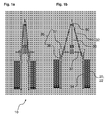
- FIGs 6a and 6b show in detail views the upward movement of the pivot lever 45 at hydraulic extension of the lifting cylinder 46.
- Fig. 6a illustrates the idle state when the chassis is not used. In this case, the lifting cylinder 46 is pushed completely together and the pivot lever rests on the base frame.
Landscapes
- Engineering & Computer Science (AREA)
- Chemical & Material Sciences (AREA)
- Combustion & Propulsion (AREA)
- Transportation (AREA)
- Mechanical Engineering (AREA)
- Vehicle Cleaning, Maintenance, Repair, Refitting, And Outriggers (AREA)
- Agricultural Machines (AREA)
- Guiding Agricultural Machines (AREA)
Applications Claiming Priority (1)
| Application Number | Priority Date | Filing Date | Title |
|---|---|---|---|
| DE200610053683 DE102006053683A1 (de) | 2006-11-13 | 2006-11-13 | Fahrgestell mit Rädern oder Raupenlaufwerk |
Publications (3)
| Publication Number | Publication Date |
|---|---|
| EP1920995A2 true EP1920995A2 (fr) | 2008-05-14 |
| EP1920995A3 EP1920995A3 (fr) | 2008-12-24 |
| EP1920995B1 EP1920995B1 (fr) | 2010-10-20 |
Family
ID=38668992
Family Applications (1)
| Application Number | Title | Priority Date | Filing Date |
|---|---|---|---|
| EP20070119470 Active EP1920995B1 (fr) | 2006-11-13 | 2007-10-29 | Châssis de véhicule à roues et/ou chenillé à écartement variable |
Country Status (2)
| Country | Link |
|---|---|
| EP (1) | EP1920995B1 (fr) |
| DE (2) | DE102006053683A1 (fr) |
Cited By (8)
| Publication number | Priority date | Publication date | Assignee | Title |
|---|---|---|---|---|
| EP2181915A1 (fr) * | 2008-10-28 | 2010-05-05 | CLAAS Selbstfahrende Erntemaschinen GmbH | Axe de dolly et formation de véhicule utilisant celui-ci |
| GB2468031A (en) * | 2009-02-20 | 2010-08-25 | Terry Deakin | Extendible width trailer for container handling |
| WO2010094935A1 (fr) * | 2009-02-20 | 2010-08-26 | Terry Deakin | Remorque extensible latéralement pour manipuler des charges telles que des conteneurs |
| GB2478632A (en) * | 2010-03-02 | 2011-09-14 | South Bank Univ Entpr Ltd | Folding trailer |
| CN103121377A (zh) * | 2013-01-04 | 2013-05-29 | 现代农装科技股份有限公司 | 轮距可调的高地隙自走式底盘及拖拉机轮距调节方法 |
| EP2955039A1 (fr) * | 2014-06-13 | 2015-12-16 | Helmut Fliegl | Dispositif de réception de remorque de véhicule |
| US9930821B2 (en) | 2015-02-18 | 2018-04-03 | Cnh Industrial America Llc | Agricultural vehicle support frame |
| CN116194359A (zh) * | 2020-07-01 | 2023-05-30 | 汤姆·希尔曼 | 可移除的通用侧向履带延伸系统 |
Families Citing this family (3)
| Publication number | Priority date | Publication date | Assignee | Title |
|---|---|---|---|---|
| DE102015013378A1 (de) | 2015-10-18 | 2017-04-20 | Annaburger Nutzfahrzeug Gmbh | Antriebsloses landwirtschaftliches Hilfsfahrzeug |
| US11297756B2 (en) | 2018-05-21 | 2022-04-12 | Charles H. Martin | Agricultural device having a rotatable frame portion |
| WO2021161063A1 (fr) | 2020-02-11 | 2021-08-19 | Kmk Handels Gmbh | Véhicule auxiliaire |
Citations (7)
| Publication number | Priority date | Publication date | Assignee | Title |
|---|---|---|---|---|
| DE2450839A1 (de) | 1973-10-25 | 1975-04-30 | Poclain Sa | Teleskopartiger traeger |
| DE3146661A1 (de) | 1981-11-25 | 1983-06-01 | Kernforschungszentrum Karlsruhe Gmbh, 7500 Karlsruhe | Fahrzeug mit variabler fahrwerksgeometrie |
| DE3442319A1 (de) | 1984-11-20 | 1986-06-26 | Wolfgang 2153 Neu Wulmstorf Schwarz | Verstellbarer unterwagen fuer kettenfahrwerke, durch mechanisches ausklappen der kettentraeger, mit eigenem antrieb |
| EP0715030A1 (fr) | 1994-12-02 | 1996-06-05 | Caterpillar Inc. | Ensemble de train de roulement à voie variable |
| EP0973673A1 (fr) | 1997-04-11 | 2000-01-26 | Luigi Gallignani | Chassis de roulement a chenilles a ecartement variable |
| EP1140607A1 (fr) | 1998-12-16 | 2001-10-10 | Torvec, Inc. | Systeme a chenilles modulaire |
| EP1248721A1 (fr) | 2000-01-18 | 2002-10-16 | New Holland Canada, Ltd. | Systeme de train chenille en elastomere a entrainement a force et de suspension pour tracteur agricole |
Family Cites Families (7)
| Publication number | Priority date | Publication date | Assignee | Title |
|---|---|---|---|---|
| DE1175617B (de) * | 1955-01-28 | 1964-08-06 | Wilhelm Ludowici Dr Ing | Mehrzweckgeraet fuer Erdbau- und Transportarbeiten |
| GB1050526A (fr) * | 1962-07-02 | |||
| DE2018070A1 (de) * | 1970-04-15 | 1972-03-30 | Jost, Fritz, 6660 Zweibrücken | Mehrzweck - Motorfahrzeug, insbesondere Geräteträger |
| NL8500758A (nl) * | 1985-03-15 | 1986-10-01 | Texas Industries Inc | Trekker. |
| US5090720A (en) * | 1990-11-23 | 1992-02-25 | Heider Merle J | Transporting system and method for using same |
| NL9301370A (nl) * | 1993-08-06 | 1995-03-01 | Redexim Handel En Expl Mij Bv | Motorvoertuig met instelbare wielpositie. |
| WO2005021321A1 (fr) * | 2003-09-01 | 2005-03-10 | Vtb Innovations Pty Ltd | Ensemble permettant de modifier l'orientation d'un corps d'un vehicule par rapport au chassis de celui-ci |
-
2006
- 2006-11-13 DE DE200610053683 patent/DE102006053683A1/de not_active Withdrawn
-
2007
- 2007-10-29 EP EP20070119470 patent/EP1920995B1/fr active Active
- 2007-10-29 DE DE200750005399 patent/DE502007005399D1/de active Active
Patent Citations (7)
| Publication number | Priority date | Publication date | Assignee | Title |
|---|---|---|---|---|
| DE2450839A1 (de) | 1973-10-25 | 1975-04-30 | Poclain Sa | Teleskopartiger traeger |
| DE3146661A1 (de) | 1981-11-25 | 1983-06-01 | Kernforschungszentrum Karlsruhe Gmbh, 7500 Karlsruhe | Fahrzeug mit variabler fahrwerksgeometrie |
| DE3442319A1 (de) | 1984-11-20 | 1986-06-26 | Wolfgang 2153 Neu Wulmstorf Schwarz | Verstellbarer unterwagen fuer kettenfahrwerke, durch mechanisches ausklappen der kettentraeger, mit eigenem antrieb |
| EP0715030A1 (fr) | 1994-12-02 | 1996-06-05 | Caterpillar Inc. | Ensemble de train de roulement à voie variable |
| EP0973673A1 (fr) | 1997-04-11 | 2000-01-26 | Luigi Gallignani | Chassis de roulement a chenilles a ecartement variable |
| EP1140607A1 (fr) | 1998-12-16 | 2001-10-10 | Torvec, Inc. | Systeme a chenilles modulaire |
| EP1248721A1 (fr) | 2000-01-18 | 2002-10-16 | New Holland Canada, Ltd. | Systeme de train chenille en elastomere a entrainement a force et de suspension pour tracteur agricole |
Cited By (9)
| Publication number | Priority date | Publication date | Assignee | Title |
|---|---|---|---|---|
| EP2181915A1 (fr) * | 2008-10-28 | 2010-05-05 | CLAAS Selbstfahrende Erntemaschinen GmbH | Axe de dolly et formation de véhicule utilisant celui-ci |
| GB2468031A (en) * | 2009-02-20 | 2010-08-25 | Terry Deakin | Extendible width trailer for container handling |
| WO2010094935A1 (fr) * | 2009-02-20 | 2010-08-26 | Terry Deakin | Remorque extensible latéralement pour manipuler des charges telles que des conteneurs |
| GB2478632A (en) * | 2010-03-02 | 2011-09-14 | South Bank Univ Entpr Ltd | Folding trailer |
| GB2478632B (en) * | 2010-03-02 | 2012-07-18 | South Bank Univ Entpr Ltd | A trailer |
| CN103121377A (zh) * | 2013-01-04 | 2013-05-29 | 现代农装科技股份有限公司 | 轮距可调的高地隙自走式底盘及拖拉机轮距调节方法 |
| EP2955039A1 (fr) * | 2014-06-13 | 2015-12-16 | Helmut Fliegl | Dispositif de réception de remorque de véhicule |
| US9930821B2 (en) | 2015-02-18 | 2018-04-03 | Cnh Industrial America Llc | Agricultural vehicle support frame |
| CN116194359A (zh) * | 2020-07-01 | 2023-05-30 | 汤姆·希尔曼 | 可移除的通用侧向履带延伸系统 |
Also Published As
| Publication number | Publication date |
|---|---|
| EP1920995B1 (fr) | 2010-10-20 |
| DE102006053683A1 (de) | 2008-05-15 |
| DE502007005399D1 (de) | 2010-12-02 |
| EP1920995A3 (fr) | 2008-12-24 |
Similar Documents
| Publication | Publication Date | Title |
|---|---|---|
| EP1920995B1 (fr) | Châssis de véhicule à roues et/ou chenillé à écartement variable | |
| DE20313955U1 (de) | Transportwagen | |
| DE4127791A1 (de) | Sattelzug mit motorisch angetriebener abstuetzvorrichtung | |
| DE4202298C2 (de) | Fahrgestell für Nutzfahrzeug | |
| WO2020025201A1 (fr) | Attelage comprenant un véhicule tracteur et une remorque, véhicule tracteur, remorque et procédé pour la distribution de charge par essieu dans un attelage | |
| EP0734902A1 (fr) | Système transbordeur automoteur, auto-chargeant et auto-déchargeant pour conteneurs | |
| DE19752958A1 (de) | Bodenschonendes, der seitwärtigen Arbeitsweise zugängliches landwirtschaftliches Fahrzeug | |
| DE102015100815B4 (de) | Mitnahmestapler | |
| DE202017101901U1 (de) | Satteltiefladeanhänger | |
| DE202005008132U1 (de) | Multifunktionales Anhängersystem | |
| DE19703127C1 (de) | Fahrzeugunterteil mit einem bis zum Boden absenkbaren Fahrzeugrahmen | |
| DE102012015556B4 (de) | Sattelauflieger mit einer Kippermulde | |
| EP2153912A1 (fr) | Crible | |
| DE3244244A1 (de) | Lastkraftwagen fuer hilfeleistung im strassenverkehr und fuer den transport von kraftfahrzeugen | |
| WO2015052310A1 (fr) | Véhicule auxiliaire agricole non entraîné, procédé permettant son utilisation pour des transports de charges agricoles et ensemble de traction agricole | |
| DE3148041A1 (de) | "fahrzeuganhaenger" | |
| DE102018001588B4 (de) | Lastkraftwagen mit hinten abgekröpftem Rahmen und ansteckbares gekröpftes Rahmenteil zur Nachrüstung eines Lastkraftwagens | |
| EP2955039B1 (fr) | Dispositif de réception de remorque de véhicule | |
| DE102012015554A1 (de) | Muldenkipper mit einer Kippermulde | |
| DE19754414A1 (de) | Fahrzeuganhänger | |
| DE3807515C1 (en) | Supporting structure for lifting vehicles under the wheels | |
| WO2021161063A1 (fr) | Véhicule auxiliaire | |
| DE102016102226B4 (de) | Fahrzeug-Kombination, insbesondere für landwirtschaftliche Einsätze | |
| DE2110446A1 (de) | Anhaenger | |
| DE3011877A1 (de) | Fahrzeug-bodenabstuetzung |
Legal Events
| Date | Code | Title | Description |
|---|---|---|---|
| PUAI | Public reference made under article 153(3) epc to a published international application that has entered the european phase |
Free format text: ORIGINAL CODE: 0009012 |
|
| AK | Designated contracting states |
Kind code of ref document: A2 Designated state(s): AT BE BG CH CY CZ DE DK EE ES FI FR GB GR HU IE IS IT LI LT LU LV MC MT NL PL PT RO SE SI SK TR |
|
| AX | Request for extension of the european patent |
Extension state: AL BA HR MK RS |
|
| PUAL | Search report despatched |
Free format text: ORIGINAL CODE: 0009013 |
|
| AK | Designated contracting states |
Kind code of ref document: A3 Designated state(s): AT BE BG CH CY CZ DE DK EE ES FI FR GB GR HU IE IS IT LI LT LU LV MC MT NL PL PT RO SE SI SK TR |
|
| AX | Request for extension of the european patent |
Extension state: AL BA HR MK RS |
|
| 17P | Request for examination filed |
Effective date: 20090203 |
|
| 17Q | First examination report despatched |
Effective date: 20090311 |
|
| AKX | Designation fees paid |
Designated state(s): DE FR NL |
|
| GRAP | Despatch of communication of intention to grant a patent |
Free format text: ORIGINAL CODE: EPIDOSNIGR1 |
|
| GRAS | Grant fee paid |
Free format text: ORIGINAL CODE: EPIDOSNIGR3 |
|
| GRAA | (expected) grant |
Free format text: ORIGINAL CODE: 0009210 |
|
| AK | Designated contracting states |
Kind code of ref document: B1 Designated state(s): DE FR NL |
|
| REF | Corresponds to: |
Ref document number: 502007005399 Country of ref document: DE Date of ref document: 20101202 Kind code of ref document: P |
|
| REG | Reference to a national code |
Ref country code: NL Ref legal event code: T3 |
|
| PLBE | No opposition filed within time limit |
Free format text: ORIGINAL CODE: 0009261 |
|
| STAA | Information on the status of an ep patent application or granted ep patent |
Free format text: STATUS: NO OPPOSITION FILED WITHIN TIME LIMIT |
|
| 26N | No opposition filed |
Effective date: 20110721 |
|
| REG | Reference to a national code |
Ref country code: DE Ref legal event code: R097 Ref document number: 502007005399 Country of ref document: DE Effective date: 20110721 |
|
| PGFP | Annual fee paid to national office [announced via postgrant information from national office to epo] |
Ref country code: NL Payment date: 20111025 Year of fee payment: 5 |
|
| PGFP | Annual fee paid to national office [announced via postgrant information from national office to epo] |
Ref country code: FR Payment date: 20121031 Year of fee payment: 6 |
|
| REG | Reference to a national code |
Ref country code: NL Ref legal event code: V1 Effective date: 20130501 |
|
| PG25 | Lapsed in a contracting state [announced via postgrant information from national office to epo] |
Ref country code: NL Free format text: LAPSE BECAUSE OF NON-PAYMENT OF DUE FEES Effective date: 20130501 |
|
| REG | Reference to a national code |
Ref country code: FR Ref legal event code: ST Effective date: 20140630 |
|
| PG25 | Lapsed in a contracting state [announced via postgrant information from national office to epo] |
Ref country code: FR Free format text: LAPSE BECAUSE OF NON-PAYMENT OF DUE FEES Effective date: 20131031 |
|
| PGFP | Annual fee paid to national office [announced via postgrant information from national office to epo] |
Ref country code: DE Payment date: 20231018 Year of fee payment: 17 |