EP1920901A2 - Vorrichtung zur Halterung von Matrizen - Google Patents
Vorrichtung zur Halterung von Matrizen Download PDFInfo
- Publication number
- EP1920901A2 EP1920901A2 EP07017540A EP07017540A EP1920901A2 EP 1920901 A2 EP1920901 A2 EP 1920901A2 EP 07017540 A EP07017540 A EP 07017540A EP 07017540 A EP07017540 A EP 07017540A EP 1920901 A2 EP1920901 A2 EP 1920901A2
- Authority
- EP
- European Patent Office
- Prior art keywords
- tool holder
- spray head
- sealing web
- sealing
- longitudinal axis
- Prior art date
- Legal status (The legal status is an assumption and is not a legal conclusion. Google has not performed a legal analysis and makes no representation as to the accuracy of the status listed.)
- Granted
Links
Images

Classifications
-
- B—PERFORMING OPERATIONS; TRANSPORTING
- B29—WORKING OF PLASTICS; WORKING OF SUBSTANCES IN A PLASTIC STATE IN GENERAL
- B29C—SHAPING OR JOINING OF PLASTICS; SHAPING OF MATERIAL IN A PLASTIC STATE, NOT OTHERWISE PROVIDED FOR; AFTER-TREATMENT OF THE SHAPED PRODUCTS, e.g. REPAIRING
- B29C48/00—Extrusion moulding, i.e. expressing the moulding material through a die or nozzle which imparts the desired form; Apparatus therefor
- B29C48/25—Component parts, details or accessories; Auxiliary operations
- B29C48/30—Extrusion nozzles or dies
- B29C48/32—Extrusion nozzles or dies with annular openings, e.g. for forming tubular articles
- B29C48/325—Extrusion nozzles or dies with annular openings, e.g. for forming tubular articles being adjustable, i.e. having adjustable exit sections
-
- B—PERFORMING OPERATIONS; TRANSPORTING
- B29—WORKING OF PLASTICS; WORKING OF SUBSTANCES IN A PLASTIC STATE IN GENERAL
- B29C—SHAPING OR JOINING OF PLASTICS; SHAPING OF MATERIAL IN A PLASTIC STATE, NOT OTHERWISE PROVIDED FOR; AFTER-TREATMENT OF THE SHAPED PRODUCTS, e.g. REPAIRING
- B29C48/00—Extrusion moulding, i.e. expressing the moulding material through a die or nozzle which imparts the desired form; Apparatus therefor
- B29C48/03—Extrusion moulding, i.e. expressing the moulding material through a die or nozzle which imparts the desired form; Apparatus therefor characterised by the shape of the extruded material at extrusion
- B29C48/09—Articles with cross-sections having partially or fully enclosed cavities, e.g. pipes or channels
-
- B—PERFORMING OPERATIONS; TRANSPORTING
- B29—WORKING OF PLASTICS; WORKING OF SUBSTANCES IN A PLASTIC STATE IN GENERAL
- B29C—SHAPING OR JOINING OF PLASTICS; SHAPING OF MATERIAL IN A PLASTIC STATE, NOT OTHERWISE PROVIDED FOR; AFTER-TREATMENT OF THE SHAPED PRODUCTS, e.g. REPAIRING
- B29C48/00—Extrusion moulding, i.e. expressing the moulding material through a die or nozzle which imparts the desired form; Apparatus therefor
- B29C48/03—Extrusion moulding, i.e. expressing the moulding material through a die or nozzle which imparts the desired form; Apparatus therefor characterised by the shape of the extruded material at extrusion
- B29C48/06—Rod-shaped
-
- B—PERFORMING OPERATIONS; TRANSPORTING
- B29—WORKING OF PLASTICS; WORKING OF SUBSTANCES IN A PLASTIC STATE IN GENERAL
- B29C—SHAPING OR JOINING OF PLASTICS; SHAPING OF MATERIAL IN A PLASTIC STATE, NOT OTHERWISE PROVIDED FOR; AFTER-TREATMENT OF THE SHAPED PRODUCTS, e.g. REPAIRING
- B29C48/00—Extrusion moulding, i.e. expressing the moulding material through a die or nozzle which imparts the desired form; Apparatus therefor
- B29C48/03—Extrusion moulding, i.e. expressing the moulding material through a die or nozzle which imparts the desired form; Apparatus therefor characterised by the shape of the extruded material at extrusion
- B29C48/09—Articles with cross-sections having partially or fully enclosed cavities, e.g. pipes or channels
- B29C48/10—Articles with cross-sections having partially or fully enclosed cavities, e.g. pipes or channels flexible, e.g. blown foils
-
- B—PERFORMING OPERATIONS; TRANSPORTING
- B29—WORKING OF PLASTICS; WORKING OF SUBSTANCES IN A PLASTIC STATE IN GENERAL
- B29C—SHAPING OR JOINING OF PLASTICS; SHAPING OF MATERIAL IN A PLASTIC STATE, NOT OTHERWISE PROVIDED FOR; AFTER-TREATMENT OF THE SHAPED PRODUCTS, e.g. REPAIRING
- B29C48/00—Extrusion moulding, i.e. expressing the moulding material through a die or nozzle which imparts the desired form; Apparatus therefor
- B29C48/25—Component parts, details or accessories; Auxiliary operations
- B29C48/30—Extrusion nozzles or dies
- B29C48/32—Extrusion nozzles or dies with annular openings, e.g. for forming tubular articles
- B29C48/34—Cross-head annular extrusion nozzles, i.e. for simultaneously receiving moulding material and the preform to be coated
Definitions
- the invention relates to a device with a tool holder for positioning of dies in the region of a spray head, in which the tool holder is arranged adjustable.
- Such devices are used, for example, to perform in extrusion devices for the production of hoses or cable sheathing axial adjustment of the tool by adjusting the tool holder relative to the spray head.
- the tool holder must in this case be adjustable for a light and with little effort, but a gap resulting for the spray head must be sealed to the other so 'that in the direction of the spray head no material can pass through the gap.
- the tool holder is pressed by a corresponding bias against the spray head and it is thereby minimized the gap width. Due to the bias of the tool holder relative to the spray head resulting from the prevailing process pressure expansion of the spray head is also compensated.
- Object of the present invention is to construct a device of the aforementioned type such that both a high sealing effect and a slight adjustability can be achieved.
- the tool holder has at least one flexible sealing ridge which is arranged inclined relative to a support longitudinal axis.
- the sealing web material pressure Due to the inclined arrangement of the flexible sealing web, it is possible to increase the sealing effect by acting on the sealing web material pressure, characterized in that the sealing web is pressed by the material pressure against an associated reference surface. Without acting material pressure, the sealing bar is unloaded and can be positioned relative to the reference surface.
- An increased sealing effect can be achieved in that at least two sealing webs are arranged substantially parallel to each other.
- the sealing web is arranged substantially radially to the support longitudinal axis.
- An increased sealing effect of the slats under internal pressures is achieved by extending the sealing web, starting from a base body of the tool holder with an expansion component against a material conveying direction.
- a typical angle of inclination is defined by the fact that the sealing web has an inclination in an angular range of 20 to 70 degrees relative to the support longitudinal axis.
- a good compromise between sufficient mechanical stability and elastic flexibility is provided by the fact that the angle of inclination is about 45 degrees.
- an increasing with increasing product pressures sealing effect is achieved in that the sealing ridge is arranged inclined so that when an internal pressure occurs in a housing interior of the spray head a contact pressure of the sealing ridge is given to a pressure surface of the spray head.
- a change in position of the tool holder is supported by the fact that the tool holder is mounted on at least one sliding disk.
- a preferred application is the fact that the spray head is designed for the extrusion of products.
- the spray head is designed for the production of tubular products.
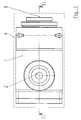
- FIG. 1 shows a side view of the device.
- a housing (1) is provided with a material inlet (2) and a material outlet (3).
- the housing (1) is formed as part of a spray head (4).
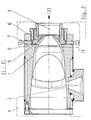
- the spray head (4) is provided with a tool holder (6) which is provided for holding a die.
- the tool holder (6) is arranged adjustable relative to the spray head (4) and is locked in a preselected position by a fixing element (7).
- the fixing element (7) can be designed, for example, as a screw bolt.
- the tool holder (6) In the region of its extension facing a contact surface (8) of the spray head (4), the tool holder (6) has flexible sealing webs (9).
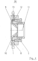
- Fig. 3 shows the spray head (4) in a front view according to viewing direction III in Fig. 2. It can be seen that a plurality of fixing elements (7) are used. In the illustrated embodiment, four substantially uniformly distributed relative to each other over a circumference fixing elements (7) are used.
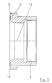
- Fig. 4 shows an enlarged view of the detail IV of Fig. 2.
- the sealing webs (9) of the tool holder (6) are clearly visible.
- the sealing webs (9) are arranged substantially parallel to each other slots (10).
- the sealing webs (9) are inclined relative to a support longitudinal axis (11).
- the inclination is in this case provided in such a way that the sealing webs (9) are pressed against the pressure surface (8) when pressure is applied from a housing interior (12).
- the sealing webs (9) therefore extend starting from a base body (13) of the tool holder (6) with a decreasing distance to the longitudinal axis of the support (11).
- the inclination angle of the sealing webs (9) is about 40 ° degrees.
- Fig. 5 shows the tool holder (6) in a direction removed from the spray head (4) positioning. Again, the inclined course of the sealing webs (9) is clearly visible.
Landscapes
- Engineering & Computer Science (AREA)
- Mechanical Engineering (AREA)
- Manufacturing & Machinery (AREA)
- Coating Apparatus (AREA)
- Extrusion Moulding Of Plastics Or The Like (AREA)
- Casting Or Compression Moulding Of Plastics Or The Like (AREA)
- Eye Examination Apparatus (AREA)
- Shaping Of Tube Ends By Bending Or Straightening (AREA)
- Mounting, Exchange, And Manufacturing Of Dies (AREA)
- Encapsulation Of And Coatings For Semiconductor Or Solid State Devices (AREA)
Abstract
Description
- Die Erfindung betrifft eine Vorrichtung mit einem Werkzeughalter zur Positionierung von Matrizen im Bereich eines Spritzkopfes, bei der der werkzeughalter verstellbar angeordnet ist.
- Derartige Vorrichtungen werden beispielsweise verwendet, um bei Extrusionseinrichtungen zur Herstellung von Schläuchen oder Kabelummantelungen eine axiale Justierung des Werkzeuges durch Verstellung des werkzeughalters relativ zum Spritzkopf durchzuführen. Der werkzeughalter muß hierbei zum einen leicht und mit geringem Kraftaufwand verstellbar sein, ein sich zum Spritzkopf ergebender Spalt muß aber zum anderen derart abgedichtet werden,' daß in Richtung auf den Spritzkopf kein Material durch den Spalt hindurchtreten kann.
- Gemäß dem Stand der Technik wird der Werkzeughalter durch eine entsprechende vorspannung gegen den Spritzkopf gepreßt und es wird hierdurch die Spaltbreite minimiert. Durch die Vorspannung des Werkzeughalters relativ zum Spritzkopf wird ebenfalls eine aus dem herrschenden Prozeßdruck resultierende Dehnung des Spritzkopfes ausgeglichen.
- Die gemäß dem Stand der Technik eingesetzte Anpressung des Werkzeughalters an den Spritzkopf erfordert aufgrund der miteinander in Kontakt tretenden Flächen hohe Anpreßdrücke, um die erforderlichen Flächenpressungen bereitzustellen. Die großen Anpreßkräfte müssen andererseits bei einer Verstellung des Werkzeuges überwunden werden. In der Regel sind deshalb spezielle Verstellschrauben mit zugehörigen Hilfswerkzeugen erforderlich.
- Aufgabe der vorliegenden Erfindung ist es, eine Vorrichtung der einleitend genannten Art derart zu konstruieren, daß sowohl eine hohe Dichtwirkung als auch eine leichte Verstellbarkeit erreicht werden.
- Diese Aufgabe wird erfindungsgemäß dadurch gelöst, daß der Werkzeughalter mindestens einen flexiblen Dichtsteg aufweist, der relativ zu einer Halterungslängsachse geneigt angeordnet ist.
- Durch die geneigte Anordnung des flexiblen Dichtsteges ist es möglich, bei einem auf den Dichtsteg einwirkenden Materialdruck die Dichtwirkung dadurch zu erhöhen, daß der Dichtsteg durch den Materialdruck gegen eine zugeordnete Bezugsfläche gepreßt wird. Ohne einwirkenden Materialdruck ist der Dichtsteg hingegen unbelastet und kann relativ zur Bezugsfläche positioniert werden.
- Eine erhöhte Dichtwirkung kann dadurch erreicht werden, daß mindestens zwei Dichtstege im wesentlichen parallel zueinander angeordnet sind.
- Für die Durchführung von Extrusionsvorgängen erweist es sich als vorteilhaft, daß der Dichtsteg im wesentlichen radial zur Halterungslängsachse angeordnet ist.
- Eine erhöhte Dichtwirkung der Lamellen bei einwirkenden Innendrücken wird dadurch erreicht, daß sich der Dichtsteg ausgehend von einem Grundkörper des Werkzeughalters mit einer Ausdehnungskomponente entgegen einer Materialförderrichtung erstreckt.
- Ein typischer Neigungswinkel ist dadurch definiert, daß der Dichtsteg relativ zur Halterungslängsachse eine Neigung in einem Winkelbereich von 20 bis 70 Grad aufweist.
- Ein guter Kompromiß zwischen einer ausreichenden mechanischen Stabilität und einer elastischen Biegbarkeit wird dadurch bereitgestellt, daß der Neigungswinkel etwa 45 Grad beträgt.
- Insbesondere wird eine bei steigenden Produktdrücken zunehmende Dichtwirkung dadurch erreicht, daß der Dichtsteg derart geneigt angeordnet ist, daß bei Auftreten eines Innendruckes in einem Gehäuseinnenraum des Spritzkopfes eine Anpressung des Dichtsteges an eine Andruckfläche des Spritzkopfes vorgegeben ist.
- Eine Positionsveränderung des Werkzeughalters wird dadurch unterstützt, daß der Werkzeughalter auf mindestens einer Gleitscheibe gelagert ist.
- Aufgrund der leichten verstellbarkeit des werkzeughalters bei gleichzeitig hoher Dichtwirkung ist es möglich, daß der Werkzeughalter mit einer automatischen Verstellung gekoppelt ist.
- Eine bevorzugte Anwendung ist darin zu sehen, daß der Spritzkopf zur Extrusion von Produkten ausgebildet ist.
- Insbesondere ist daran gedacht, daß der Spritzkopf zur Herstellung von schlauchartigen Produkten ausgebildet ist.
- In den Zeichnungen sind Ausführungsbeispiele der Erfindung schematisch dargestellt. Es zeigen:
- Fig. 1
- eine Seitenansicht einer Vorrichtung mit Spritzkopf und Werkzeughalter zur Positionierung von Matrizen,
- Fig. 2
- ein Längsschnitt gemäß Schnittlinie II-II in Fig. 1,
- Fig. 3
- eine Seitenansicht gemäß Blickrichtung III in Fig. 2,
- Fig. 4
- eine vergrößerte Darstellung der Einzelheit IV in Fig. 2 und
- Fig. 5
- eine vergrößerte Darstellung eines Längsschnittes durch den Werkzeughalter.
- Fig. 1 zeigt eine Seitenansicht der Vorrichtung. Ein Gehäuse (1) ist mit einem Materialeintritt (2) sowie einem Materialauslaß (3) versehen. Das Gehäuse (1) ist als Teil eines Spritzkopfes (4) ausgebildet.
- Aus dem Längsschnitt in Fig. 2 ist zu erkennen, daß der Spritzkopf (4) mit einem Werkzeughalter (6) versehen ist, der zur Halterung einer Matrize vorgesehen ist. Der Werkzeughalter (6) ist relativ zum Spritzkopf (4) verstellbar angeordnet und wird in einer vorgewählten Position von einem Fixierelement (7) arretiert. Das Fixierelement (7) kann beispielsweise als Schraubenbolzen ausgeführt sein.
- Im Bereich seiner einer Andruckfläche (8) des Spritzkopfes (4) zugewandten Ausdehnung weist der Werkzeughalter (6) flexible Dichtstege (9) auf.
- Fig. 3 zeigt den Spritzkopf (4) in einer Frontalansicht gemäß Blickrichtung III in Fig. 2. Es ist zu erkennen, daß eine Mehrzahl von Fixierelementen (7) verwendet werden. Beim dargestellten Ausführungsbeispiel sind vier im wesentlichen relativ zueinander gleichmäßig über einen Umfang verteilte Fixierelemente (7) verwendet.
- Fig. 4 zeigt eine vergrößerte Darstellung der Einzelheit IV aus Fig. 2. Es sind insbesondere die Dichtstege (9) des Werkzeughalters (6) klar zu erkennen. Durch die Dichtstege (9) werden im wesentlichen parallel zueinander angeordnete Schlitze (10) begrenzt. Die Dichtstege (9) verlaufen relativ zu einer Halterungslängsachse (11) geneigt. Die Neigung ist hierbei derart vorgesehen, daß die Dichtstege (9) bei einer von einem Gehäuseinnenraum (12) ausgehenden Druckbeaufschlagung gegen die Andruckfläche (8) gepreßt werden. Die Dichtstege (9) verlaufen deshalb ausgehend von einem Grundkörper (13) des werkzeughalters (6) mit einem abnehmenden Abstand zur Halterungslängsachse (11). Beim dargestellten Ausführungsbeispiel beträgt der Neigungswinkel der Dichtstege (9) etwa 40 °Grad.
- Fig. 5 zeigt den Werkzeughalter (6) in einer vom Spritzkopf (4) abgenommenen Positionierung. Auch hier ist noch einmal der geneigte Verlauf der Dichtstege (9) deutlich zu erkennen.
Claims (11)
- Vorrichtung mit einem Werkzeughalter zur Positionierung von Matrizen im Bereich eines Spritzkopfes, bei der der werkzeughalter verstellbar angeordnet ist, dadurch gekennzeichnet, daß der Werkzeughalter (6) mindestens einen flexiblen Dichtsteg (9) aufweist, der relativ zu einer Halterungslängsachse (11) geneigt angeordnet ist.
- Vorrichtung nach Anspruch 1, dadurch gekennzeichnet, daß mindestens zwei Dichtstege (9) im wesentlichen parallel zueinander angeordnet sind.
- Vorrichtung nach einem der Ansprüche 1 oder 2, dadurch gekennzeichnet, daß der Dichtsteg (9) im wesentlichen radial zur Halterungslängsachse (11) angeordnet ist.
- Vorrichtung nach einem der Ansprüche 1 bis 3, dadurch gekennzeichnet, daß sich der Dichtsteg (9) ausgehend von einem Grundkörper (13) des Werkzeughalters (6) mit einer Ausdehnungskomponente entgegen einer Materialförderrichtung erstreckt.
- vorrichtung nach einem der Ansprüche 1 bis 4, dadurch gekennzeichnet, daß der Dichtsteg (9) relativ zur Halterungslängsachse (11) eine Neigung in einem Winkelbereich von 20 bis 70 Grad aufweist.
- Vorrichtung nach Anspruch 5, dadurch gekennzeichnet, daß der Neigungswinkel etwa 45 Grad beträgt.
- Vorrichtung nach einem der Ansprüche 1 bis 6, dadurch gekennzeichnet, daß der Dichtsteg (9) derart geneigt angeordnet ist, daß bei Auftreten eines Innendruckes in einem Gehäuseinnenraum (12) des Spritzkopfes (4) eine Anpressung des Dichtsteges (9) an eine Andruckfläche (8) des Spritzkopfes (4) vorgegeben ist.
- Vorrichtung nach einem der Ansprüche 1 bis 7, dadurch gekennzeichnet, daß der Werkzeughalter (6) auf mindestens einer Gleitscheibe gelagert ist.
- Vorrichtung nach einem der Ansprüche 1 bis 8, dadurch gekennzeichnet, daß der Werkzeughalter (6) mit einer automatischen Verstellung gekoppelt ist.
- Vorrichtung nach einem der Ansprüche 1 bis 9, dadurch gekennzeichnet, daß der Spritzkopf (4) zur Extrusion von Produkten ausgebildet ist.
- Vorrichtung nach einem der Ansprüche 1 bis 10, dadurch gekennzeichnet, daß der Spritzkopf (4) zur Herstellung von schlauchartigen Produkten ausgebildet ist.
Applications Claiming Priority (1)
| Application Number | Priority Date | Filing Date | Title |
|---|---|---|---|
| DE102006053224.4A DE102006053224B4 (de) | 2006-11-11 | 2006-11-11 | Vorrichtung zur Halterung von Matrizen |
Publications (3)
| Publication Number | Publication Date |
|---|---|
| EP1920901A2 true EP1920901A2 (de) | 2008-05-14 |
| EP1920901A3 EP1920901A3 (de) | 2009-02-25 |
| EP1920901B1 EP1920901B1 (de) | 2010-01-27 |
Family
ID=39156266
Family Applications (1)
| Application Number | Title | Priority Date | Filing Date |
|---|---|---|---|
| EP07017540A Not-in-force EP1920901B1 (de) | 2006-11-11 | 2007-09-07 | Vorrichtung zur Halterung von Matrizen |
Country Status (4)
| Country | Link |
|---|---|
| EP (1) | EP1920901B1 (de) |
| AT (1) | ATE456441T1 (de) |
| DE (2) | DE102006053224B4 (de) |
| RU (1) | RU2457110C2 (de) |
Cited By (1)
| Publication number | Priority date | Publication date | Assignee | Title |
|---|---|---|---|---|
| JP2008290367A (ja) * | 2007-05-25 | 2008-12-04 | Canon Inc | 押出し機および該押出し機を用いたローラの製造方法 |
Family Cites Families (7)
| Publication number | Priority date | Publication date | Assignee | Title |
|---|---|---|---|---|
| SU1209979A1 (ru) * | 1984-11-15 | 1986-02-07 | Предприятие П/Я А-7467 | Торцевое уплотнение вращающегос вала |
| JPS6225029A (ja) * | 1985-07-25 | 1987-02-03 | Taigaasu Polymer Kk | 偏肉調整装置 |
| JPS6255118A (ja) * | 1985-09-04 | 1987-03-10 | Showa Electric Wire & Cable Co Ltd | クロスヘツドの芯出し方法 |
| SU1656255A1 (ru) * | 1989-04-25 | 1991-06-15 | Львовский политехнический институт им.Ленинского комсомола | Уплотнительное устройство |
| DE19719220C2 (de) * | 1997-05-07 | 1999-09-16 | Troester Maschf Paul | Querspritzkopf einer Extrusionsanlage |
| US6382944B1 (en) * | 1998-11-10 | 2002-05-07 | Guill Tool & Engineering Co., Inc. | Universally mounted adjustable die |
| DE10062590B4 (de) * | 2000-12-15 | 2005-12-29 | Fränkische Rohrwerke Gebr. Kirchner GmbH + Co. KG | Düsenanordnung zur Coextrusion |
-
2006
- 2006-11-11 DE DE102006053224.4A patent/DE102006053224B4/de not_active Expired - Fee Related
-
2007
- 2007-09-07 EP EP07017540A patent/EP1920901B1/de not_active Not-in-force
- 2007-09-07 AT AT07017540T patent/ATE456441T1/de active
- 2007-09-07 DE DE502007002732T patent/DE502007002732D1/de active Active
- 2007-11-09 RU RU2007141692/05A patent/RU2457110C2/ru not_active IP Right Cessation
Cited By (1)
| Publication number | Priority date | Publication date | Assignee | Title |
|---|---|---|---|---|
| JP2008290367A (ja) * | 2007-05-25 | 2008-12-04 | Canon Inc | 押出し機および該押出し機を用いたローラの製造方法 |
Also Published As
| Publication number | Publication date |
|---|---|
| EP1920901B1 (de) | 2010-01-27 |
| EP1920901A3 (de) | 2009-02-25 |
| RU2007141692A (ru) | 2009-05-20 |
| DE502007002732D1 (de) | 2010-03-18 |
| DE102006053224A1 (de) | 2008-05-15 |
| RU2457110C2 (ru) | 2012-07-27 |
| DE102006053224B4 (de) | 2015-08-13 |
| ATE456441T1 (de) | 2010-02-15 |
Similar Documents
| Publication | Publication Date | Title |
|---|---|---|
| EP2712702B1 (de) | Bandfinishvorrichtung, Bandfinishsystem und Verfahren zur Herstellung einer Bandfinishvorrichtung | |
| EP3921089B1 (de) | Auftragsdüse | |
| DE9110998U1 (de) | Rohrverbindung | |
| WO2011015186A2 (de) | Endklemme zur befestigung gerahmter pv-module | |
| DE10318137B3 (de) | Stufenlos einstellbare Kalibrierhülse für extrudierte Kunststoffstränge, insbesondere Kunststoffrohre | |
| EP2371473A1 (de) | Vorrichtung zur teilweisen Entschichtung von Rohren, insbesondere von Rohren aus Metall | |
| EP1920901B1 (de) | Vorrichtung zur Halterung von Matrizen | |
| EP0515449B1 (de) | Vorrichtung zum schneiden und reinigen von gegenständen mittels eines wasser-abrasivmittel-gemisches bei hohem umgebungsdruck | |
| DE202005012296U1 (de) | Rohrleitungspassstück | |
| DE112005002667T5 (de) | Beschichtungsdüse mit Schnellmontagemerkmalen | |
| DE10220640A1 (de) | Verfahren und Vorrichtung zum Abtrennen von Scheiben von einem Werkstück | |
| DE19847104C1 (de) | Mehrwellige Schneckenmaschine | |
| DE2213581C3 (de) | Vorrichtung zum Verschrauben zweier Fenster- oder Türenbauteile | |
| DE10128700A1 (de) | Klemmring zum axialen Verbinden von zylindrischen Bauteilen | |
| EP2408577B1 (de) | Umformwerkzeug, insbesondere knetwerkzeug | |
| DE19944131A1 (de) | Klemmring | |
| DE3804498C2 (de) | ||
| DE102015105481A1 (de) | Profilverbinder | |
| EP3574973B1 (de) | Filteranordnung | |
| DE19852673C1 (de) | Variabel montierbarer Profilstab zur Verwendung als Säule, Ausleger, Traverse, Strebe oder dergleichen für Vorrichtungen | |
| DE202023104107U1 (de) | Rohrprofil | |
| EP2480736B1 (de) | Schutzprofil für fenster- oder türrahmen | |
| EP3199247B9 (de) | Schlitzgiesser sowie beschichtungsanlage | |
| EP4464296A1 (de) | Deckenbefestigungsvorrichtung für medizingeräte | |
| AT503322A1 (de) | Umformwerkzeug, insbesondere knetwerkzeug |
Legal Events
| Date | Code | Title | Description |
|---|---|---|---|
| PUAI | Public reference made under article 153(3) epc to a published international application that has entered the european phase |
Free format text: ORIGINAL CODE: 0009012 |
|
| AK | Designated contracting states |
Kind code of ref document: A2 Designated state(s): AT BE BG CH CY CZ DE DK EE ES FI FR GB GR HU IE IS IT LI LT LU LV MC MT NL PL PT RO SE SI SK TR |
|
| AX | Request for extension of the european patent |
Extension state: AL BA HR MK RS |
|
| PUAL | Search report despatched |
Free format text: ORIGINAL CODE: 0009013 |
|
| AK | Designated contracting states |
Kind code of ref document: A3 Designated state(s): AT BE BG CH CY CZ DE DK EE ES FI FR GB GR HU IE IS IT LI LT LU LV MC MT NL PL PT RO SE SI SK TR |
|
| AX | Request for extension of the european patent |
Extension state: AL BA HR MK RS |
|
| 17P | Request for examination filed |
Effective date: 20090306 |
|
| GRAP | Despatch of communication of intention to grant a patent |
Free format text: ORIGINAL CODE: EPIDOSNIGR1 |
|
| AKX | Designation fees paid |
Designated state(s): AT BE BG CH CY CZ DE DK EE ES FI FR GB GR HU IE IS IT LI LT LU LV MC MT NL PL PT RO SE SI SK TR |
|
| GRAS | Grant fee paid |
Free format text: ORIGINAL CODE: EPIDOSNIGR3 |
|
| GRAA | (expected) grant |
Free format text: ORIGINAL CODE: 0009210 |
|
| AK | Designated contracting states |
Kind code of ref document: B1 Designated state(s): AT BE BG CH CY CZ DE DK EE ES FI FR GB GR HU IE IS IT LI LT LU LV MC MT NL PL PT RO SE SI SK TR |
|
| REG | Reference to a national code |
Ref country code: GB Ref legal event code: FG4D Free format text: NOT ENGLISH |
|
| REG | Reference to a national code |
Ref country code: CH Ref legal event code: EP |
|
| REG | Reference to a national code |
Ref country code: IE Ref legal event code: FG4D |
|
| REF | Corresponds to: |
Ref document number: 502007002732 Country of ref document: DE Date of ref document: 20100318 Kind code of ref document: P |
|
| REG | Reference to a national code |
Ref country code: NL Ref legal event code: T3 |
|
| LTIE | Lt: invalidation of european patent or patent extension |
Effective date: 20100127 |
|
| PG25 | Lapsed in a contracting state [announced via postgrant information from national office to epo] |
Ref country code: IS Free format text: LAPSE BECAUSE OF FAILURE TO SUBMIT A TRANSLATION OF THE DESCRIPTION OR TO PAY THE FEE WITHIN THE PRESCRIBED TIME-LIMIT Effective date: 20100527 Ref country code: LT Free format text: LAPSE BECAUSE OF FAILURE TO SUBMIT A TRANSLATION OF THE DESCRIPTION OR TO PAY THE FEE WITHIN THE PRESCRIBED TIME-LIMIT Effective date: 20100127 Ref country code: ES Free format text: LAPSE BECAUSE OF FAILURE TO SUBMIT A TRANSLATION OF THE DESCRIPTION OR TO PAY THE FEE WITHIN THE PRESCRIBED TIME-LIMIT Effective date: 20100508 Ref country code: PT Free format text: LAPSE BECAUSE OF FAILURE TO SUBMIT A TRANSLATION OF THE DESCRIPTION OR TO PAY THE FEE WITHIN THE PRESCRIBED TIME-LIMIT Effective date: 20100527 |
|
| REG | Reference to a national code |
Ref country code: IE Ref legal event code: FD4D |
|
| PG25 | Lapsed in a contracting state [announced via postgrant information from national office to epo] |
Ref country code: FI Free format text: LAPSE BECAUSE OF FAILURE TO SUBMIT A TRANSLATION OF THE DESCRIPTION OR TO PAY THE FEE WITHIN THE PRESCRIBED TIME-LIMIT Effective date: 20100127 Ref country code: LV Free format text: LAPSE BECAUSE OF FAILURE TO SUBMIT A TRANSLATION OF THE DESCRIPTION OR TO PAY THE FEE WITHIN THE PRESCRIBED TIME-LIMIT Effective date: 20100127 Ref country code: PL Free format text: LAPSE BECAUSE OF FAILURE TO SUBMIT A TRANSLATION OF THE DESCRIPTION OR TO PAY THE FEE WITHIN THE PRESCRIBED TIME-LIMIT Effective date: 20100127 Ref country code: SI Free format text: LAPSE BECAUSE OF FAILURE TO SUBMIT A TRANSLATION OF THE DESCRIPTION OR TO PAY THE FEE WITHIN THE PRESCRIBED TIME-LIMIT Effective date: 20100127 |
|
| REG | Reference to a national code |
Ref country code: SK Ref legal event code: T3 Ref document number: E 7335 Country of ref document: SK |
|
| PG25 | Lapsed in a contracting state [announced via postgrant information from national office to epo] |
Ref country code: RO Free format text: LAPSE BECAUSE OF FAILURE TO SUBMIT A TRANSLATION OF THE DESCRIPTION OR TO PAY THE FEE WITHIN THE PRESCRIBED TIME-LIMIT Effective date: 20100127 Ref country code: EE Free format text: LAPSE BECAUSE OF FAILURE TO SUBMIT A TRANSLATION OF THE DESCRIPTION OR TO PAY THE FEE WITHIN THE PRESCRIBED TIME-LIMIT Effective date: 20100127 Ref country code: CY Free format text: LAPSE BECAUSE OF FAILURE TO SUBMIT A TRANSLATION OF THE DESCRIPTION OR TO PAY THE FEE WITHIN THE PRESCRIBED TIME-LIMIT Effective date: 20100127 Ref country code: SE Free format text: LAPSE BECAUSE OF FAILURE TO SUBMIT A TRANSLATION OF THE DESCRIPTION OR TO PAY THE FEE WITHIN THE PRESCRIBED TIME-LIMIT Effective date: 20100127 Ref country code: GR Free format text: LAPSE BECAUSE OF FAILURE TO SUBMIT A TRANSLATION OF THE DESCRIPTION OR TO PAY THE FEE WITHIN THE PRESCRIBED TIME-LIMIT Effective date: 20100428 Ref country code: IE Free format text: LAPSE BECAUSE OF FAILURE TO SUBMIT A TRANSLATION OF THE DESCRIPTION OR TO PAY THE FEE WITHIN THE PRESCRIBED TIME-LIMIT Effective date: 20100127 |
|
| PG25 | Lapsed in a contracting state [announced via postgrant information from national office to epo] |
Ref country code: CZ Free format text: LAPSE BECAUSE OF FAILURE TO SUBMIT A TRANSLATION OF THE DESCRIPTION OR TO PAY THE FEE WITHIN THE PRESCRIBED TIME-LIMIT Effective date: 20100127 Ref country code: BG Free format text: LAPSE BECAUSE OF FAILURE TO SUBMIT A TRANSLATION OF THE DESCRIPTION OR TO PAY THE FEE WITHIN THE PRESCRIBED TIME-LIMIT Effective date: 20100427 |
|
| PLBE | No opposition filed within time limit |
Free format text: ORIGINAL CODE: 0009261 |
|
| STAA | Information on the status of an ep patent application or granted ep patent |
Free format text: STATUS: NO OPPOSITION FILED WITHIN TIME LIMIT |
|
| 26N | No opposition filed |
Effective date: 20101028 |
|
| PG25 | Lapsed in a contracting state [announced via postgrant information from national office to epo] |
Ref country code: DK Free format text: LAPSE BECAUSE OF FAILURE TO SUBMIT A TRANSLATION OF THE DESCRIPTION OR TO PAY THE FEE WITHIN THE PRESCRIBED TIME-LIMIT Effective date: 20100127 |
|
| BERE | Be: lapsed |
Owner name: HARBURG-FREUDENBERGER MASCHINENBAU G.M.B.H. Effective date: 20100930 |
|
| PG25 | Lapsed in a contracting state [announced via postgrant information from national office to epo] |
Ref country code: MC Free format text: LAPSE BECAUSE OF NON-PAYMENT OF DUE FEES Effective date: 20100930 |
|
| REG | Reference to a national code |
Ref country code: FR Ref legal event code: ST Effective date: 20110531 |
|
| PG25 | Lapsed in a contracting state [announced via postgrant information from national office to epo] |
Ref country code: FR Free format text: LAPSE BECAUSE OF NON-PAYMENT OF DUE FEES Effective date: 20100930 Ref country code: BE Free format text: LAPSE BECAUSE OF NON-PAYMENT OF DUE FEES Effective date: 20100930 |
|
| PG25 | Lapsed in a contracting state [announced via postgrant information from national office to epo] |
Ref country code: MT Free format text: LAPSE BECAUSE OF FAILURE TO SUBMIT A TRANSLATION OF THE DESCRIPTION OR TO PAY THE FEE WITHIN THE PRESCRIBED TIME-LIMIT Effective date: 20100127 |
|
| REG | Reference to a national code |
Ref country code: CH Ref legal event code: PL |
|
| GBPC | Gb: european patent ceased through non-payment of renewal fee |
Effective date: 20110907 |
|
| PG25 | Lapsed in a contracting state [announced via postgrant information from national office to epo] |
Ref country code: LI Free format text: LAPSE BECAUSE OF NON-PAYMENT OF DUE FEES Effective date: 20110930 Ref country code: CH Free format text: LAPSE BECAUSE OF NON-PAYMENT OF DUE FEES Effective date: 20110930 |
|
| PG25 | Lapsed in a contracting state [announced via postgrant information from national office to epo] |
Ref country code: GB Free format text: LAPSE BECAUSE OF NON-PAYMENT OF DUE FEES Effective date: 20110907 |
|
| PG25 | Lapsed in a contracting state [announced via postgrant information from national office to epo] |
Ref country code: HU Free format text: LAPSE BECAUSE OF FAILURE TO SUBMIT A TRANSLATION OF THE DESCRIPTION OR TO PAY THE FEE WITHIN THE PRESCRIBED TIME-LIMIT Effective date: 20100728 Ref country code: LU Free format text: LAPSE BECAUSE OF NON-PAYMENT OF DUE FEES Effective date: 20100907 |
|
| REG | Reference to a national code |
Ref country code: AT Ref legal event code: MM01 Ref document number: 456441 Country of ref document: AT Kind code of ref document: T Effective date: 20120907 |
|
| PGFP | Annual fee paid to national office [announced via postgrant information from national office to epo] |
Ref country code: TR Payment date: 20130823 Year of fee payment: 7 |
|
| PG25 | Lapsed in a contracting state [announced via postgrant information from national office to epo] |
Ref country code: AT Free format text: LAPSE BECAUSE OF NON-PAYMENT OF DUE FEES Effective date: 20120907 |
|
| PGFP | Annual fee paid to national office [announced via postgrant information from national office to epo] |
Ref country code: DE Payment date: 20140722 Year of fee payment: 8 |
|
| PGFP | Annual fee paid to national office [announced via postgrant information from national office to epo] |
Ref country code: SK Payment date: 20140904 Year of fee payment: 8 |
|
| PGFP | Annual fee paid to national office [announced via postgrant information from national office to epo] |
Ref country code: IT Payment date: 20140923 Year of fee payment: 8 |
|
| PGFP | Annual fee paid to national office [announced via postgrant information from national office to epo] |
Ref country code: NL Payment date: 20140918 Year of fee payment: 8 |
|
| REG | Reference to a national code |
Ref country code: DE Ref legal event code: R119 Ref document number: 502007002732 Country of ref document: DE |
|
| PG25 | Lapsed in a contracting state [announced via postgrant information from national office to epo] |
Ref country code: IT Free format text: LAPSE BECAUSE OF NON-PAYMENT OF DUE FEES Effective date: 20150907 |
|
| REG | Reference to a national code |
Ref country code: SK Ref legal event code: MM4A Ref document number: E 7335 Country of ref document: SK Effective date: 20150907 Ref country code: NL Ref legal event code: MM Effective date: 20151001 |
|
| PG25 | Lapsed in a contracting state [announced via postgrant information from national office to epo] |
Ref country code: DE Free format text: LAPSE BECAUSE OF NON-PAYMENT OF DUE FEES Effective date: 20160401 |
|
| PG25 | Lapsed in a contracting state [announced via postgrant information from national office to epo] |
Ref country code: SK Free format text: LAPSE BECAUSE OF NON-PAYMENT OF DUE FEES Effective date: 20150907 Ref country code: NL Free format text: LAPSE BECAUSE OF NON-PAYMENT OF DUE FEES Effective date: 20151001 |
|
| PG25 | Lapsed in a contracting state [announced via postgrant information from national office to epo] |
Ref country code: TR Free format text: LAPSE BECAUSE OF NON-PAYMENT OF DUE FEES Effective date: 20150907 |