EP1920795B1 - Medical device inserted in body cavity - Google Patents
Medical device inserted in body cavity Download PDFInfo
- Publication number
- EP1920795B1 EP1920795B1 EP06782837.6A EP06782837A EP1920795B1 EP 1920795 B1 EP1920795 B1 EP 1920795B1 EP 06782837 A EP06782837 A EP 06782837A EP 1920795 B1 EP1920795 B1 EP 1920795B1
- Authority
- EP
- European Patent Office
- Prior art keywords
- curved portion
- present
- plane
- curved
- stylet
- Prior art date
- Legal status (The legal status is an assumption and is not a legal conclusion. Google has not performed a legal analysis and makes no representation as to the accuracy of the status listed.)
- Not-in-force
Links
Images




Classifications
-
- A—HUMAN NECESSITIES
- A61—MEDICAL OR VETERINARY SCIENCE; HYGIENE
- A61M—DEVICES FOR INTRODUCING MEDIA INTO, OR ONTO, THE BODY; DEVICES FOR TRANSDUCING BODY MEDIA OR FOR TAKING MEDIA FROM THE BODY; DEVICES FOR PRODUCING OR ENDING SLEEP OR STUPOR
- A61M31/00—Devices for introducing or retaining media, e.g. remedies, in cavities of the body
-
- A—HUMAN NECESSITIES
- A61—MEDICAL OR VETERINARY SCIENCE; HYGIENE
- A61M—DEVICES FOR INTRODUCING MEDIA INTO, OR ONTO, THE BODY; DEVICES FOR TRANSDUCING BODY MEDIA OR FOR TAKING MEDIA FROM THE BODY; DEVICES FOR PRODUCING OR ENDING SLEEP OR STUPOR
- A61M25/00—Catheters; Hollow probes
- A61M25/0021—Catheters; Hollow probes characterised by the form of the tubing
- A61M25/0041—Catheters; Hollow probes characterised by the form of the tubing pre-formed, e.g. specially adapted to fit with the anatomy of body channels
-
- A—HUMAN NECESSITIES
- A61—MEDICAL OR VETERINARY SCIENCE; HYGIENE
- A61M—DEVICES FOR INTRODUCING MEDIA INTO, OR ONTO, THE BODY; DEVICES FOR TRANSDUCING BODY MEDIA OR FOR TAKING MEDIA FROM THE BODY; DEVICES FOR PRODUCING OR ENDING SLEEP OR STUPOR
- A61M25/00—Catheters; Hollow probes
- A61M25/01—Introducing, guiding, advancing, emplacing or holding catheters
-
- A—HUMAN NECESSITIES
- A61—MEDICAL OR VETERINARY SCIENCE; HYGIENE
- A61M—DEVICES FOR INTRODUCING MEDIA INTO, OR ONTO, THE BODY; DEVICES FOR TRANSDUCING BODY MEDIA OR FOR TAKING MEDIA FROM THE BODY; DEVICES FOR PRODUCING OR ENDING SLEEP OR STUPOR
- A61M25/00—Catheters; Hollow probes
- A61M25/01—Introducing, guiding, advancing, emplacing or holding catheters
- A61M25/09—Guide wires
-
- A—HUMAN NECESSITIES
- A61—MEDICAL OR VETERINARY SCIENCE; HYGIENE
- A61M—DEVICES FOR INTRODUCING MEDIA INTO, OR ONTO, THE BODY; DEVICES FOR TRANSDUCING BODY MEDIA OR FOR TAKING MEDIA FROM THE BODY; DEVICES FOR PRODUCING OR ENDING SLEEP OR STUPOR
- A61M25/00—Catheters; Hollow probes
- A61M25/01—Introducing, guiding, advancing, emplacing or holding catheters
- A61M25/09—Guide wires
- A61M2025/09116—Design of handles or shafts or gripping surfaces thereof for manipulating guide wires
-
- A—HUMAN NECESSITIES
- A61—MEDICAL OR VETERINARY SCIENCE; HYGIENE
- A61M—DEVICES FOR INTRODUCING MEDIA INTO, OR ONTO, THE BODY; DEVICES FOR TRANSDUCING BODY MEDIA OR FOR TAKING MEDIA FROM THE BODY; DEVICES FOR PRODUCING OR ENDING SLEEP OR STUPOR
- A61M25/00—Catheters; Hollow probes
- A61M25/01—Introducing, guiding, advancing, emplacing or holding catheters
- A61M25/09—Guide wires
- A61M2025/09133—Guide wires having specific material compositions or coatings; Materials with specific mechanical behaviours, e.g. stiffness, strength to transmit torque
- A61M2025/09141—Guide wires having specific material compositions or coatings; Materials with specific mechanical behaviours, e.g. stiffness, strength to transmit torque made of shape memory alloys which take a particular shape at a certain temperature
Definitions
- the present invention relates to a medical apparatus for insertion into a body cavity and, more particularly, to a medical apparatus for insertion into a body cavity which can spontaneously control the direction thereof and deliver the distal tip to a predesignated object portion in a living organ accurately and easily by pushing the apparatus into a body cavity.
- a stylet made of an elastic linear body is used for insertion of a flexible tubular medical apparatus such as a pacing lead for artificially giving stimuli to the muscle of heart or sensing the intracardiac potential, a catheter for injecting high calorie infusion into a middle cardiac vein and an endotracheal tube inserted into the trachea to surely maintain the air way.
- a flexible tubular medical apparatus such as a pacing lead for artificially giving stimuli to the muscle of heart or sensing the intracardiac potential
- a guide wire made of an elastic linear body is inserted into a blood vessel and, then, a catheter is inserted to the predesignated position in the blood vessel along the guide wire.
- the apparatus for insertion into the body cavity such as the stylet and the guide wire is pushed into a blood vessel having curves in complicated shapes and branches
- excellent skill is required to deliver the distal tip to the predesignated object portion without causing damages to the blood vessel and without straying into portions different from the object portion.
- a mistake in the operation causes problems such as cardiac perforation, cardiac tamponade, pneumothorax and hemothorax.
- a linear stylet having the entirely linear shape, a J-shaped stylet having a distal tip portion bent in the J-shape and a steerable stylet which can provide shapes to the distal tip portion by manipulation by hands are used at present.
- the linear stylet has a drawback in that selecting the blood vessel correctly at branches is difficult and delivering the stylet to the object portion is difficult although the insertion through a perforation is easy.
- the J-shaped stylet has a drawback in that, although selecting the blood vessel correctly at the first branch is easy, selecting the blood vessel correctly at the second branch beyond the first branch is difficult.
- the steerable stylet has a drawback in that the stylet tends to be expensive and the distal tip portion tends to become hard due to the complicated mechanism although the blood vessel is selected correctly by suitably manipulating the distal tip portion every time the distal tip reaches a branch and the stylet can be pushed into the blood vessel correctly. Therefore, development of a medical apparatus for insertion into a body cavity which can be manipulated easily and can deliver the distal tip to the object portion easily and safely has been attempted.
- a stylet unit which provides a suitable J-shape to the free end portion of an electrode cable in the atrium so that introduction of the end portion of the cable into the auricle of the atrium and fixing of the contacting electrode to the pole of the auricle of the atrium are facilitated
- a stylet unit having an inner stylet in which a stylet portion having a shape predesignated in advance is formed at a portion before the free end portion which is bent in advance and the radius of curvature of the stylet portion is in the opposite direction to the radius of curvature of the free end portion is proposed (Patent Reference 1).
- Figure 12 shows a diagram exhibiting the side view of an example of the above stylet unit.
- the radius of curvature ⁇ 2 of the stylet portion 17 is in the direction opposite to the direction of the radius of curvature ⁇ 1 of the free end portion 18 which is bent in advance.
- the radius of curvature ⁇ 2 of the stylet portion 17 is at the left hand side of the stylet, and the radius of curvature ⁇ 1 of the end portion 22 is at the right hand side of the stylet.
- a catheter having a stylet which can be inserted into a blood vessel having branches and, in particular, into the ascending main vein in the high calorie infusion therapy accurately without straying into other blood vessels and without causing damages to the blood vessel
- FIG 13 shows a diagram exhibiting the side view of an example of the above catheter having a stylet.
- the catheter 23 is composed of a distal tip portion 24, a main portion 25 and a base portion 26.
- the stylet 27 is composed of a distal tip portion 28, a main portion 29 and a base end portion 30.
- the stylet 27 is inserted through the inner cavity of the catheter 23, and a catheter connector 31 and a stylet connector 32 are fitted to each other at the base end portion.
- the distal tip portion of the catheter 24 and the main portion of the catheter 25 are bent at approximately the same positions as the positions of the distal tip portion of the stylet 28 and the main portion of the stylet 29, respectively.
- the catheter has a second curved portion 34 at the distal side relative to the first curved portion 33.
- the stylet 27 does not protrude from the tip of the catheter 35.
- Patent Reference 3 ( WO 99/ 23958A1 ) discloses a guide wire with a helical distal guide section.
- Patent Reference 4 ( US 2005/113862A1 ) provides a guide wire with steerable section.
- Patent Reference 5 ( US 5295493A ) provides an apparatus for intoducing an atherectomy cutter into a coronary artery for removing a stenosis from the artery, including a guide wire having a predetermined anatomically shaped configuration.
- Patent Reference 6 ( EP 0745407A2 ) provides a guiding introducer for use in the treatment of atrial flutter and/or atrial fibrillation in the right atrium, having a first section of generally straight section, the second section of C-shaped section, the third section.
- Patent Reference 7 ( US 6558368B1 ) provides a catheter comprising a elongate catheter body being bendably formed near the distal end to impinge against the wall of the aorta opposite the ostium of the coronary artery.
- the present invention as defined in claims 1-8 has an object of providing a medical apparatus for insertion into a body cavity which can spontaneously control the direction thereof and deliver the distal tip to a predesignated object portion in a living organ accurately and easily by pushing the apparatus into a body cavity.
- a medical apparatus for insertion into a body cavity which comprises a linear elastic body and can deliver the distal tip to a predesignated object portion of a living organ
- the property of spontaneously controlling the direction could be provided to the medical apparatus for insertion into a body cavity and the distal tip of the medical apparatus for insertion into a body cavity proceeded along the predesignated route in the body cavity and reached the predesignated object portion of the living organ by just pushing the proximal portion of the medical apparatus for insertion into a body cavity without transfer of a torque by rotation of the proximal portion of the apparatus when curved portions were formed three-dimensionally between the proximal side and the distal side of the elastic linear body in accordance with the shape of the body cavity from the open portion or the perforation of the body cavity to the predesignated object portion.
- the present invention has been completed based on the knowledge.
- Figure 1 shows diagrams exhibiting a side view and a plan view of an embodiment of the medical apparatus for insertion into a body cavity of the present invention.
- Figure 2 shows diagrams exhibiting a side view and a plan view of another embodiment of the medical apparatus for insertion into a body cavity of the present invention.
- Figure 3 shows a diagram exhibiting a side view of an embodiment of the stylet of the present invention.
- Figure 4 shows a diagram exhibiting a side view of another embodiment of the stylet of the present invention.
- Figure 5 shows a diagram exhibiting a side view of still another embodiment of the stylet of the present invention.
- Figure 6 shows a diagram exhibiting a side view of still another embodiment of the stylet of the present invention.
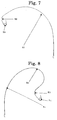
- Figure 7 shows a diagram exhibiting a side view of still another embodiment of the stylet of the present invention.
- Figure 8 shows a diagram exhibiting a side view of still another embodiment of the stylet of the present invention.
- Figure 9 shows a diagram exhibiting a side view of still another embodiment of the stylet of the present invention.
- Figure 10 shows a diagram exhibiting a side view of still another embodiment of the stylet of the present invention.
- Figure 11 shows a diagram exhibiting a jig for pushing the stylet used in Examples into a body cavity.
- Figure 12 shows a diagram exhibiting a side view of an example of a conventional stylet unit.
- Figure 13 shows a diagram exhibiting a side view of an example of a conventional catheter having a stylet.
- reference numerals mean as follows: 1: a linear portion at a proximal portion; 2: a first curved portion; 3: a first intermediate linear portion; 4: a second curved portion; 5: a second intermediate linear portion; 6: a linear portion at a distal tip; 7: a linear portion at a proximal portion; 8: a first curved portion; 9: a first intermediate linear portion; 10: a second curved portion; 11: a second intermediate linear portion; 12: a third curved portion; 13: a linear portion at a distal tip; 14: a pushing plate; 15: a ball bearing; 16: a clip; 17: a stylet portion; 18: a free end portion; 19.
- a base end 20: a stopping ball; 21: a stylet; 22: a distal tip portion; 23: a catheter; 24: a distal tip portion; 25: a main portion; 26: a base end portion; 27: a stylet; 28: a distal tip portion; 29: a main portion; 30: a base end portion; 31: a catheter connector; 32: a stylet connector; 33: a first curved portion; 34: a second curved portion; and 35: a distal tip.
- the medical apparatus for insertion into a body cavity of the present invention comprises an elastic linear body and delivers the distal tip to a predesignated object portion in a living organ, wherein the elastic linear body comprises a plurality of curved portions between the proximal side and the distal side, and at least one pair of adjacent curved portions are present on different planes which intersect each other.
- FIG. 1 shows diagrams exhibiting a side view and a plan view of an embodiment of a medical apparatus for insertion into a body cavity of the present invention which is not in accordance with the subject matters of the claims.
- the medical apparatus for insertion into a body cavity of the present embodiment comprises a linear portion at the proximal portion 1, a first curved portion 2 having a radius of curvature R 1 , a first intermediate linear portion 3, a second curved portion 4 having a radius of curvature R 2 , a second intermediate linear portion 5 and a linear portion at the distal tip 6 between the proximal side and the distal side the linear elastic body.
- the linear portion at the proximal portion and the first intermediate linear portion are present on the plane on which the first curved portion is present.
- the second intermediate linear portion is present on the plane on which the second curved portion is present.
- FIG. 2 shows diagrams exhibiting a side view and a plan view of another embodiment of a medical apparatus for insertion into a body cavity of the present invention which is not in accordance with the subject matters of the claims.
- the medical apparatus for insertion into a body cavity of the present embodiment comprises a linear portion at the proximal portion 7, a first curved portion 8 having a radius of curvature R 1 , a first intermediate linear portion 9, a second curved portion 10 having a radius of curvature R 2 , a second intermediate linear portion 11, a third curved portion 12 having a radius of curvature R 3 and a linear portion at the distal tip 13 between the proximal side and the distal side of the linear elastic body.
- the linear portion at the proximal portion and the first intermediate linear portion are present on the plane on which the first curved portion is present.
- the second intermediate linear portion is present on the plane on which the second curved portion is present.
- the shape of a curved portion is a perfect arc shape but may be an approximate arc shape in accordance with the shape of the body cavity.
- the radius of curvature of an approximate arc shape can be obtained as the average value of the minimum radius of curvature and the maximum radius of curvature of the approximate arc shape.
- the angle of intersection of planes on which a pair of adjacent curved portions are present can be obtained as follows.
- a plane on which the n-th curved portion is present and a plane on which the (n+1)-th plane is present are disposed in a manner such that the plane on which the n-th curved portion is present is placed at the proximal side and the plane on which the (n+1)-th plane is present is placed at the distal side.
- the angle formed with the plane on which the n-th curved portion is present and the plane on which the (n+1)-th plane is present with respect to the line of intersection of the two planes as measured in the counter-clockwise direction is defined as the angle of intersection of the planes.
- Examples of the elastic linear body used in the present invention include stainless steel wires, platinum wires, gold wires and nickel-titanium alloy wires.
- Examples of the living organ to which the medical apparatus for insertion into a body cavity of the present invention is applied include the heart, the large vein, the trachea, the lung and the bladder.
- the medical apparatus for insertion into a body cavity of the present invention can be advantageously used as a preshaped stylet facilitating selective insertion of a catheter, a combination of a catheter with a preshaped stylet, a sheathing, a guide wire or a cannula.
- the medical apparatus for insertion into a body cavity of the present invention can be advantageously used as a stylet for an indwelling electrode for a cardiac pacemaker which works to replace the function of the living organ or a catheter for examination and curing of heart diseases.
- a curved portion disposed closer to the distal side has a radius of curvature smaller than a radius of curvature of a curved portion disposed closer to the proximal side.
- the tip of the electrode is lead to the right atrium or the right ventricle and disposed at the object portion such as the Bachmann's bundle, the septum, the pulmonary artery or the auricle
- the radius of curvature of the blood vessel decreases as the tip of the electrode approaches the object portion away from the subclavian vein.
- the medical apparatus for insertion into a body cavity When the medical apparatus for insertion into a body cavity is shaped in a manner such that a curved portion disposed closer to the distal side has a radius of curvature smaller than the radius of curvature of a curved portion disposed closer to the proximal side, the medical apparatus for insertion into a body cavity exhibits the property of spontaneously controlling the direction in accordance with the shape of the body cavity.
- the medical apparatus for insertion into a body cavity selects the direction correctly and proceeds by simply pushing the medical apparatus into the body cavity through the cut open portion or the perforation without adding any torque of rotation at the proximal portion of the medical apparatus, and the distal tip is delivered accurately to the predesignated object portion of the living organ without straying into other branches of the body cavity.
- the second curved portion of the medical apparatus for insertion into a body cavity is already in the direction of the next branch in the body cavity as the medical apparatus for insertion into a body cavity is automatically placed along the first curved portion of the body cavity. Therefore, the distal tip of the medical apparatus for insertion into a body cavity can be placed in the correct direction in the body cavity due to the internal rotating force without applying any torque of rotation at the portion of insertion, and the direction can be easily controlled.
- the maximum value of the radius of curvature of a curved portion is 80 mm or greater and more preferably 90 mm or greater, and the minimum value of the radius of curvature of a curved portion is 40 mm or smaller and preferably 20 mm or smaller.
- the radius of curvature of the first curved portion in the body cavity is 80 mm or greater, and the radius of curvature of the curved portion closest to the object portion is 40 mm or smaller.
- the distal tip of the medical apparatus for insertion into a body cavity can be smoothly and easily delivered to the predesignated object portion of the living organ by adjusting the maximum value of the radius of curvature of a curved portion of the medical apparatus for insertion into a body cavity to 80 mm or greater and the minimum value of the radius of curvature of a curved portion to 40 mm or smaller.
- the medical apparatus for insertion into a body cavity of the present invention may be a stylet in which the elastic linear body is a metal wire having a diameter of 0.1 to 1 mm and preferably 0.2 to 0.6 mm and a handle is disposed at the proximal portion.
- the diameter of the elastic linear body is smaller than 0.1 mm, there is the possibility that rigidity necessary for pushing the stylet into the body cavity is insufficient.
- the diameter of the elastic linear body exceeds 1 mm, rigidity is excessively great, and there is the possibility that proceeding through curved portions of the body cavity with deformation becomes difficult.
- the shape of the handle at the proximal portion is not particularly limited. It is preferable that the handle has a columnar shape.
- the length of the handle having a columnar shape is 10 to 60 mm and more preferably 20 to 50 mm. It is preferable that the outer diameter of the handle having a columnar shape is 4 to 20 mm and more preferably 6 to 12 mm.
- the stylet exhibits the property of spontaneously controlling the direction and proceeds through the body cavity with rotation along curves of the body cavity. It is sufficient that the handle at the proximal portion is pushed forward in accordance with the spontaneous rotation of the stylet and, therefore, the handle having a columnar shape is advantageously used.
- the material for the handle at the proximal portion is not particularly limited. Examples of the material include polyamides and polycarbonates.
- the medical apparatus for insertion into a body cavity of the present invention may be a catheter in which the elastic linear body comprises an elastic macromolecular tubular body and a core wire inserted through the tubular body.
- the material of the elastic macromolecular tubular body is not particularly limited. Examples of the material of the elastic macromolecular tubular body include polyethylene, polyamides and polyurethanes.
- the material of the core wire is not particularly limited. Examples of the core wire include stainless steel wires and nickel-titanium alloy wires.
- the proceeding into the body cavity can be facilitated when rigidity is decreased by decreasing the diameter of the core wire in portions closer to the distal tip portion, for example, by forming a tapered shape having the diameter decreasing from 0.35 mm to 0.02 mm.
- a sphere is attached by welding to the distal tip of the core wire so that damages on the inner lumen is prevented during insertion of the core wire into the elastic macromolecular tubular body.
- the medical apparatus for insertion into a body cavity of the present invention may have a construction such that at least a portion of the elastic linear body comprises a shape memory material, and the radius of curvature of the portion comprising the shape memory material decreases when the portion is inserted into the body cavity.
- the radius of curvature of the elastic linear body described above is the radius of curvature decreased after being inserted into the body cavity.
- the insertion into the body cavity can be facilitated due to the greater radius of curvature, making the shape closer to the straight line, before the apparatus is inserted into the body cavity, and the property of spontaneously controlling the direction is exhibited by forming the curved portion having the predesignated radius of curvature after being inserted into the body cavity.
- the shape memory material used above include nickel-titanium-based shape memory alloys and iron-manganese-silicon-based shape memory alloys.
- the medical apparatus for insertion into a body cavity of the present invention is a stylet having two curved portions and inserted from the left subclavian vein to the Bachmann's bundle as the object portion.
- the length of the entire stylet is 442 to 662 mm, more preferably 497 to 607 mm and most preferably 524 to 580 mm.
- the first curved portion is curved in the leftward direction, and the directions of curve of the first curved portion and the second curved portion are the same with each other.
- the radius of curvature of the first curved portion is 80.5 to 120.8 mm, more preferably 90.6 to 110.7 mm and most preferably 95.6 to 105.7 mm.
- the radius of curvature of the second curved portion is 12.6 to 18.8 mm, more preferably 14.1 to 17.3 mm and most preferably 14.9 to 16.5 mm.
- the angle of intersection between the plane on which the first curved portion is present and the plane on which the second curved portion is present is 250° ⁇ 20°, more preferably 250° ⁇ 10° and most preferably 250° ⁇ 5°.
- the length of the linear portion at the distal tip is 5 to 15 mm.
- the angle of intersection between the plane on which the second curved portion is present and the linear portion at the distal tip is -20° to +20° and more preferably -10° to +10°.
- Figure 3 shows a diagram exhibiting the side view of the stylet of the present embodiment.
- the medical apparatus for insertion into a body cavity of the present invention is a stylet having three curved portions and inserted from the right subclavian vein to the Bachmann's bundle as the object portion.
- the length of the entire stylet is 442 to 662 mm, more preferably 497 to 607 mm and most preferably 524 to 580 mm.
- the first curved portion is curved in the rightward direction.
- the directions of curve of the first curved portion and the second curved portion are the same with each other, and the directions of curve of the second curved portion and the third curved portion are opposite to each other.
- the radius of curvature of the first curved portion is 90.9 to 136.4 mm, more preferably 102.3 to 125.0 mm and most preferably 108.0 to 119.3 mm.
- the radius of curvature of the second curved portion is 24.7 to 37.1 mm, more preferably 27.8 to 34.0 mm and most preferably 29.4 to 32.5 mm.
- the radius of curvature of the third curved portion is 11.5 to 17.3 mm, more preferably 13.0 to 15.9 mm and most preferably 13.7 to 15.2 mm.
- the angle of intersection between the plane on which the first curved portion is present and the plane on which the second curved portion is present is 0° ⁇ 20°, more preferably 0° ⁇ 10° and most preferably 0° ⁇ 5°.
- the angle of intersection between the plane on which the second curved portion is present and the plane on which the third curved portion is present is 230° ⁇ 20°, more preferably 230° ⁇ 10° and most preferably 230° ⁇ 5°.
- the length of the linear portion at the distal tip is 5 to 15 mm.
- the angle of intersection between the plane on which the third curved portion is present and the linear portion at the distal tip is -20° to +20° and more preferably -10° to +10°.
- the distance between the plane on which the first curved portion is present and the distal tip is 18.5 to 27.8 mm, more preferably 20.8 to 25.5 mm and most preferably 22.0 to 24.3 mm.
- Figure 4 shows a diagram exhibiting the side view of the stylet of the present embodiment.
- the medical apparatus for insertion into a body cavity of the present invention is a stylet having four curved portions and inserted from the left subclavian vein to the septum as the object portion.
- the length of the entire stylet is 496 to 744 mm, more preferably 558 to 682 mm and most preferably 589 to 651 mm.
- the first curved portion is curved in the leftward direction.
- the directions of curve of the first curved portion and the second curved portion are the same with each other, the directions of curve of the second curved portion and the third curved portion are the same with each other, and the directions of curve of the third curved portion and the fourth curved portion are opposite to each other.
- the radius of curvature of the first curved portion is 66.4 to 99.6 mm, more preferably 74.7 to 91.3 mm and most preferably 78.9 to 87.2 mm.
- the radius of curvature of the second curved portion is 66.7 to 100.0 mm, more preferably 75.0 to 91.7 mm and most preferably 79.2 to 87.5 mm.
- the radius of curvature of the third curved portion is 17.4 to 26.2 mm, more preferably 19.6 to 24.0 mm and most preferably 20.7 to 22.9 mm.
- the radius of curvature of the fourth curved portion is 6.6 to 9.9 mm, more preferably 7.4 to 9.1 mm and most preferably 7.8 to 8.6 mm.
- the angle of intersection between the plane on which the first curved portion is present and the plane on which the second curved portion is present is 0° ⁇ 20°, more preferably 0° ⁇ 10° and most preferably 0° ⁇ 5°.
- the angle of intersection between the plane on which the second curved portion is present and the plane on which the third curved portion is present is 220° ⁇ 20°, more preferably 220° ⁇ 10 and most preferably 220° ⁇ 5.
- the angle of intersection between the plane on which the third curved portion is present and the plane on which the fourth curved portion is present is 330° ⁇ 20°, more preferably 330° ⁇ 10° and most preferably 330° ⁇ 5°.
- the length of the linear portion at the distal tip is 10 to 20 mm.
- the angle of intersection between the plane on which the fourth curved portion is present and the linear portion at the distal tip is -20° to +20° and more preferably -10° to +10°.
- the distance between the plane on which the first curved portion is present and the distal tip is 36.4 to 54.6 mm, more preferably 41.0 to 50.1 mm and most preferably 43.2 to 47.8 mm.
- Figure 5 shows a diagram exhibiting the side view of the stylet of the present embodiment.
- the medical apparatus for insertion into a body cavity of the present invention is a stylet having four curved portions and inserted from the right subclavian vein to the septum as the object portion.
- the length of the entire stylet is 496 to 744 mm, more preferably 558 to 682 mm and most preferably 589 to 651 mm.
- the first curved portion is curved in the rightward direction.
- the directions of curve of the first curved portion and the second curved portion are opposite to each other, the directions of curve of the second curved portion and the third curved portion are the same with each other, and the directions of curve of the third curved portion and the fourth curved portion are opposite to each other.
- the radius of curvature of the first curved portion is 42.7 to 64.0 mm, more preferably 48.0 to 58.7 mm and most preferably 50.7 to 56.0 mm.
- the radius of curvature of the second curved portion is 46.4 to 69.6 mm, more preferably 52.2 to 63.8 mm and most preferably 55.1 to 60.9 mm.
- the radius of curvature of the third curved portion is 18.3 to 27.4 mm, more preferably 20.6 to 25.2 mm and most preferably 21.7 to 24.0 mm.
- the radius of curvature of the fourth curved portion is 6.3 to 9.4 mm, more preferably 7.0 to 8.6 mm and most preferably 7.4 to 8.2 mm.
- the angle of intersection between the plane on which the first curved portion is present and the plane on which the second curved portion is present is 150° ⁇ 20°, more preferably 150° ⁇ 10° and most preferably 150° ⁇ 5°.
- the angle of intersection between the plane on which the second curved portion is present and the plane on which the third curved portion is present is 230° ⁇ 20°, more preferably 230° ⁇ 10° and most preferably 230° ⁇ 5°.
- the angle of intersection between the plane on which the third curved portion is present and the plane on which the fourth curved portion is present is 320° ⁇ 20°, more preferably 320° ⁇ 10° and most preferably 320° ⁇ 5°.
- the length of the linear portion at the distal tip is 10 to 20 mm.
- the angle of intersection between the plane on which the fourth curved portion is present and the linear portion at the distal tip is -20° to +20° and more preferably -10° to +10°.
- the distance between the plane on which the first curved portion is present and the distal tip is 48.0 to 72.0 mm, more preferably 54.0 to 66.0 mm and most preferably 57.0 to 63.0 mm.
- Figure 6 shows a diagram exhibiting the side view of the stylet of the present embodiment.
- the medical apparatus for insertion into a body cavity of the present invention is a stylet having three curved portions and inserted from the left subclavian vein to the pulmonary artery as the object portion.
- the length of the entire stylet is 496 to 744 mm, more preferably 558 to 682 mm and most preferably 589 to 651 mm.
- the first curved portion is curved in the leftward direction.
- the directions of curve of the first curved portion and the second curved portion are the same with each other, and the directions of curve of the second curved portion and the third curved portion are the same with each other.
- the radius of curvature of the first curved portion is 141.1 to 211.6 mm, more preferably 158.7 to 194.0 and most preferably 167.5 to 185 mm.
- the radius of curvature of the second curved portion is 17.3 to 26.0 mm, more preferably 19.5 to 23.8 mm and most preferably 20.6 to 22.7 mm.
- the radius of curvature of the third curved portion is 4.6 to 6.9 mm, more preferably 5.2 to 6.3 mm and most preferably 5.4 to 6.0 mm.
- the angle of intersection between the plane on which the first curved portion is present and the plane on which the second curved portion is present is 160° ⁇ 20°, more preferably 160° ⁇ 10° and most preferably 160° ⁇ 5°.
- the angle of intersection between the plane on which the second curved portion is present and the plane on which the third curved portion is present is 160° ⁇ 20°, more preferably 160° ⁇ 10° and most preferably 160° ⁇ 5°.
- the length of the linear portion at the distal tip is 2 to 42 mm and more preferably 12 to 32 mm. It is preferable that the third curved portion has a shape of one full circle and a half, and the length between the distal tip and the point of contact of the circle is 14.8 to 20.4 mm, more preferably 16.7 to 20.4 mm and most preferably 17.6 to 19.4 mm.
- Figure 7 shows a diagram exhibiting the side view of the stylet of the present embodiment.
- the medical apparatus for insertion into a body cavity of the present invention is a stylet having four curved portions and inserted from the right subclavian vein to the pulmonary artery as the object portion.
- the length of the entire stylet is 496 to 744 mm, more preferably 558 to 682 mm and most preferably 589 to 651 mm.
- the first curved portion is curved in the rightward direction.
- the directions of curve of the first curved portion and the second curved portion are the same with each other, the directions of curve of the second curved portion and the third curved portion are opposite to each other, and the directions of curve of the third curved portion and the fourth curved portion are the same with each other.
- the radius of curvature of the first curved portion is 114.7 to 172.0 mm, more preferably 129.0 to 157.7 mm and most preferably 136.2 to 150.5 mm.
- the radius of curvature of the second curved portion is 27.2 to 40.8 mm, more preferably 30.6 to 37.4 mm and most preferably 32.3 to 35.7 mm.
- the radius of curvature of the third curved portion is 18.1 to 27.2 mm, more preferably 20.4 to 24.9 mm and most preferably 21.5 to 23.8 mm.
- the radius of curvature of the fourth curved portion is 4.6 to 6.9 mm, more preferably 5.2 to 6.3 mm and more preferably 5.4 to 6.0 mm.
- the angle of intersection between the plane on which the first curved portion is present and the plane on which the second curved portion is present is 0° ⁇ 20°, more preferably 0° ⁇ 10° and most preferably 0° ⁇ 5°.
- the angle of intersection between the plane on which the second curved portion is present and the plane on which the third curved portion is present is 140° ⁇ 20°, more preferably 140° ⁇ 10° and most preferably 140° ⁇ 5°.
- the angle of intersection between the plane on which the third curved portion is present and the plane on which the fourth curved portion is present is 190° ⁇ 20°, more preferably 190° ⁇ 10° and most preferably 190° ⁇ 5°.
- the fourth curved portion has a shape of one full circle and a half, and the length between the distal tip and the point of contact of the circle is 16.0 to 24.0 mm, more preferably 18.0 to 22.0 mm and most preferably 19.0 to 21.0 mm.
- Figure 8 shows a diagram exhibiting the side view of the stylet of the present embodiment.
- the medical apparatus for insertion into a body cavity of the present invention is a stylet having two curved portions and inserted from the left subclavian vein to the auricle as the object portion.
- the length of the entire stylet is 492 to 738 mm, more preferably 554 to 677 mm and most preferably 584 to 646 mm.
- the first curved portion is curved in the leftward direction.
- the directions of curve of the first curved portion and the second curved portion are the same with each other.
- the radius of curvature of the first curved portion is 93.9 to 140.8 mm, more preferably 105.5 to 129.1 mm and most preferably 111.5 to 123.2 mm.
- the radius of curvature of the second curved portion is 19.9 to 29.8 mm, more preferably 22.3 to 27.3 mm and most preferably 23.6 to 26.1 mm.
- the angle of intersection between the plane on which the first curved portion is present and the plane on which the second curved portion is present is 150° ⁇ 20°, more preferably 150° ⁇ 10° and most preferably 150° ⁇ 5°.
- the length of the linear portion at the distal tip is 5 to 55 mm and more preferably 15 to 45 mm.
- the angle of intersection between the plane on which the second curved portion is present and the linear portion at the distal tip is -20° to +20° and more preferably -10° to +10°.
- the distance between the plane on which the first curved portion is present and the distal tip is 20.0 to 30.0 mm, more preferably 22.5 to 27.5 mm and most preferably 23.8 to 26.3 mm.
- Figure 9 shows a diagram exhibiting the side view of the stylet of the present embodiment.
- the medical apparatus for insertion into a body cavity of the present invention is a stylet having three curved portions and inserted from the right subclavian vein to the auricle as the object portion.
- the length of the entire stylet is 496 to 744 mm, more preferably 558 to 682 mm and most preferably 589 to 651 mm.
- the first curved portion is curved in the rightward direction.
- the directions of curve of the first curved portion and the second curved portion are the same with each other, and the directions of curve of the second curved portion and the third curved portion are opposite to each other.
- the radius of curvature of the first curved portion is 96.0 to 144.0 mm, more preferably 108.0 to 132.0 mm and most preferably 114.0 to 126 mm.
- the radius of curvature of the second curved portion is 36.8 to 55.2 mm, more preferably 41,4 to 50.6 mm and most preferably 43.7 to 48.3 mm.
- the radius of curvature of the third curved portion is 16.8 to 25.2 mm, more preferably 18.9 to 23.1 mm and most preferably 20.0 to 22.1 mm.
- the angle of intersection between the plane on which the first curved portion is present and the plane on which the second curved portion is present is 0° ⁇ 20°, more preferably 0° ⁇ 10° and most preferably 0° ⁇ 5°.
- the length of the linear portion at the distal tip is 5 to 55 mm and more preferably 15 to 45 mm.
- the angle of intersection between the plane on which the second curved portion is present and the linear portion at the distal tip is -20° to +20° and more preferably -10° to +10°.
- the distance between the plane on which the first curved portion is present and the distal tip is 28.9 to 43.4 mm, more preferably 32.5 to 39.8 mm and most preferably 34.4 to 38.0 mm.
- Figure 10 shows a diagram exhibiting the side view of the stylet of the present embodiment.
- a stylet having a linear proximal portion, a first curved portion, a first intermediate linear portion, a second curved portion, a second intermediate linear portion and a linear portion at the distal tip was prepared by working a stainless steel (SUS 304) wire having a diameter of 0.35 mm and a length of 552 mm.
- the linear proximal portion, the first curved portion and the first intermediate linear portion were placed on the same plane.
- the length of the linear portion was adjusted to 123 mm.
- the first curved portion was placed in the leftward direction.
- the radius of curvature of the first curved portion was adjusted to 101 mm, and the angle around the center was adjusted to 163°.
- the length of the first intermediate linear portion was adjusted to 58 mm.
- the second curved portion having a radius of curvature of 15.7 mm and an angle around the center of 180° was placed in the same direction of curve as that of the first curved portion.
- the linear portion at the distal tip having a length of 34.6 mm was formed in the linear portion at the distal tip.
- a taper was formed in a manner such that the diameter gradually decreased from 0.35 mm at the point connected to the second curved portion to 0.02 mm at the distal tip, and a sphere having a diameter of 0.28 mm was attached to the distal tip by welding.
- the curves were formed successively from the linear portion at the distal tip to the linear proximal portion.
- the distal tip of the stylet was placed at a position separated from the plane on which the first curved portion was present by 3.05 mm.
- a model of blood vessel from the left subclavian vein to the ascending large vein was prepared by working a polyurethane tube. Branches in the blood vessel were formed in the model of the blood vessel exactly in the same shapes as those of the actual blood vessel.
- the ascending large vein in a transparent model of the heart [manufactured by Kyoto Kagaku Co., Ltd] was connected to the ascending large vein in the above model of the blood vessel.
- a jig for pushing a stylet into a body cavity shown in Figure 11 was prepared.
- a clip 16 having a diameter of 10 mm and freely rotating around a ball bearing 15 was disposed at the center of a pushing plate 14 made of stainless steel and having a length of 20 mm, a width of 40 mm and a thickness of 3 mm.
- the linear proximal portion of the above stylet was held by the clip in the jig for pushing a stylet into a body cavity.
- the distal tip of the stylet was pushed into the left subclavian vein of the model of the blood vessel by the left hand and, while the left hand was kept along the stylet, the jig for pushing a stylet into a body cavity was slowly pushed forward by the right hand.
- no torque of rotation was applied to the stylet at the proximal portion, the stylet pushed into the blood vessel exhibited the property of spontaneously controlling the direction and freely rotated, and the distal tip of the stylet accurately reached the Bachmann's bundle in the transparent model of the heart without straying into other branches of the blood vessel.
- a core wire having a linear proximal portion, a first curved portion and a second curved portion was prepared by working a wire of an ultra-elastic nickel titanium alloy having a diameter of 0.30 mm and a length of 615 mm.
- the linear proximal portion and the first curved portion were placed on the same plane.
- the length of the linear proximal portion was adjusted to 120 mm.
- the first curved portion was placed in the leftward direction.
- the radius of curvature of the first curved portion was adjusted to 117 mm, and the angle around the center was adjusted to 215°.
- the second curved portion On a plane intersecting the plane on which the first curved portion is present at an angle of 160°, the second curved portion having a radius of curvature of 24.8 mm and an angle around the center of 130° was placed in the same direction of the curve as that of the first curved portion.
- a taper was formed in a manner such that the diameter gradually decreased to 0.02 mm at the distal tip, and a sphere having a diameter of 0.28 mm was attached to the distal tip by welding.
- the tip of the core wire was placed at a position separated from the plane on which the first curved portion was present by 25.0 mm.
- the obtained core wire was inserted through a narrow tube of polyethylene of nominal number of 3Fr having an inner diameter of 0.5 mm, an outer diameter of 1 mm and a length of 615 mm, and a catheter was prepared.
- the medical apparatus for insertion into a body cavity of the present invention When the medical apparatus for insertion into a body cavity of the present invention is inserted into the body cavity, complicated operations for selecting a branch and directing the distal tip of the apparatus to the object portion by transfer of torque at the proximal portion are not necessary, and the distal tip of the apparatus can be delivered to the predesignated object portion in a living organ by simply pushing the apparatus forward at the proximal portion since the medical apparatus for insertion into a body cavity has the property of spontaneously controlling the direction.
- a catheter or the like can be quickly and easily introduced to the object portion of a living organ for the many purposes such as diagnosis, treatments, operations in a blood vessel and replacements of the function of the living organ.
- the medical apparatus for insertion into a body cavity of the present invention is useful as the stylet for placing an indwelling electrode of a pacemaker for the heart.
- a lead electrode can be placed safely and accurately at the object portion of the atrium or the ventricle pervenously without skill of a great degree.
Landscapes
- Health & Medical Sciences (AREA)
- Life Sciences & Earth Sciences (AREA)
- Animal Behavior & Ethology (AREA)
- Engineering & Computer Science (AREA)
- Anesthesiology (AREA)
- Biomedical Technology (AREA)
- Heart & Thoracic Surgery (AREA)
- Hematology (AREA)
- General Health & Medical Sciences (AREA)
- Public Health (AREA)
- Veterinary Medicine (AREA)
- Pulmonology (AREA)
- Biophysics (AREA)
- Media Introduction/Drainage Providing Device (AREA)
- Electrotherapy Devices (AREA)
Applications Claiming Priority (2)
| Application Number | Priority Date | Filing Date | Title |
|---|---|---|---|
| JP2005247929A JP4680007B2 (ja) | 2005-08-29 | 2005-08-29 | スタイレット |
| PCT/JP2006/316279 WO2007026555A1 (ja) | 2005-08-29 | 2006-08-14 | 体腔内挿入医療機器 |
Publications (3)
| Publication Number | Publication Date |
|---|---|
| EP1920795A1 EP1920795A1 (en) | 2008-05-14 |
| EP1920795A4 EP1920795A4 (en) | 2010-07-28 |
| EP1920795B1 true EP1920795B1 (en) | 2016-02-24 |
Family
ID=37808654
Family Applications (1)
| Application Number | Title | Priority Date | Filing Date |
|---|---|---|---|
| EP06782837.6A Not-in-force EP1920795B1 (en) | 2005-08-29 | 2006-08-14 | Medical device inserted in body cavity |
Country Status (4)
| Country | Link |
|---|---|
| US (1) | US20090105724A1 (https=) |
| EP (1) | EP1920795B1 (https=) |
| JP (1) | JP4680007B2 (https=) |
| WO (1) | WO2007026555A1 (https=) |
Cited By (1)
| Publication number | Priority date | Publication date | Assignee | Title |
|---|---|---|---|---|
| US11324931B2 (en) * | 2018-02-27 | 2022-05-10 | Johan Willem Pieter Marsman | Autonomous guidewire |
Families Citing this family (32)
| Publication number | Priority date | Publication date | Assignee | Title |
|---|---|---|---|---|
| US8500697B2 (en) * | 2007-10-19 | 2013-08-06 | Pressure Products Medical Supplies, Inc. | Transseptal guidewire |
| US7963947B2 (en) | 2008-01-16 | 2011-06-21 | Pressure Products Medical Supplies, Inc. | Apparatus, system, and method of shielding the sharp tip of a transseptal guidewire |
| US8096985B2 (en) | 2008-05-07 | 2012-01-17 | Guided Delivery Systems Inc. | Deflectable guide |
| EP2135638B1 (fr) | 2008-06-20 | 2015-03-11 | Ela Medical | Mandrin préformé de guidage d'une sonde en contact avec la paroi du septum |
| FR2932688B1 (fr) * | 2008-06-20 | 2013-01-25 | Ela Medical Sa | Mandrin bi-matiere de guidage d'une sonde en contact avec la paroi du septum |
| WO2010025375A1 (en) * | 2008-08-29 | 2010-03-04 | Treventis Corporation | Compositions and methods of treating amyloid disease |
| EP2389218A4 (en) * | 2009-01-20 | 2012-06-13 | Guided Delivery Systems Inc | DIAGNOSTIC CATHETERS, GUIDANCE CATHETERS, DISPLAY DEVICES AND CORDULAR PIPING DEVICES AND CORRESPONDING KITS AND METHODS |
| WO2010085456A1 (en) | 2009-01-20 | 2010-07-29 | Guided Delivery Systems Inc. | Anchor deployment devices and related methods |
| CN102395400B (zh) * | 2009-04-14 | 2014-12-03 | 泰尔茂株式会社 | 医用导丝 |
| EP2275170B1 (fr) | 2009-07-15 | 2012-08-29 | Sorin CRM SAS | Ensemble implantable dans le réseau veineux coronarien, comprenant une sonde de stimulation à vis d'ancrage |
| US10035012B2 (en) | 2010-02-22 | 2018-07-31 | Richard B. North | Percutaneous electrode |
| JP4937391B2 (ja) * | 2010-09-01 | 2012-05-23 | 日本ライフライン株式会社 | 心腔内除細動カテーテル |
| EP2691139B1 (en) | 2011-03-30 | 2016-05-18 | Dangoisse, Vincent | Guiding catheter |
| JP5042387B1 (ja) * | 2011-11-30 | 2012-10-03 | 泰夫 坂野 | 電極カテーテル |
| JP6042080B2 (ja) * | 2012-03-09 | 2016-12-14 | テルモ株式会社 | ガイドワイヤ |
| JP5508479B2 (ja) * | 2012-07-05 | 2014-05-28 | 寛治 井上 | スタイレットを有したカテーテル型治療・診断器具およびスタイレットが用いられるカテーテルチューブ |
| US20140114255A1 (en) * | 2012-10-19 | 2014-04-24 | Cook Medical Technologies Llc | Self-coiling stylet needle device |
| WO2014081942A1 (en) | 2012-11-21 | 2014-05-30 | Concert Medical, Llc | Preformed guidewire |
| JP5651257B2 (ja) * | 2014-02-12 | 2015-01-07 | 寛治 井上 | スタイレットを有したカテーテル型治療・診断器具およびスタイレットが用いられるカテーテルチューブ |
| WO2016141358A1 (en) | 2015-03-05 | 2016-09-09 | Guided Delivery Systems Inc. | Devices and methods of visualizing and determining depth of penetration in cardiac tissue |
| US20180132837A1 (en) * | 2015-05-05 | 2018-05-17 | W. L. Gore & Associates, Inc. | Shaped delivery sheath and methods |
| US10596354B2 (en) * | 2015-09-25 | 2020-03-24 | Mark Taber | Guide wires, catheters, and guide wire catheter systems and methods |
| CN205729432U (zh) * | 2015-12-30 | 2016-11-30 | 先健科技(深圳)有限公司 | 推送装置及输送系统 |
| US10737097B2 (en) * | 2016-09-16 | 2020-08-11 | Terrell M. Williams | Permanent his-bundle pacing device and method |
| CN106264687B (zh) * | 2016-11-01 | 2018-11-20 | 中南大学湘雅医院 | 可调节式动静脉穿刺针及与其配套的留置套管和外保护套 |
| US11253699B1 (en) | 2019-03-21 | 2022-02-22 | Terrell M. Williams | Cardiac pacing lead |
| ES2911668T3 (es) | 2019-08-28 | 2022-05-20 | Johan Willem Pieter Marsman | Kit de cables guía |
| US12502507B2 (en) * | 2020-01-09 | 2025-12-23 | Becton, Dickinson And Company | Multi-lumen extension system |
| CN216091818U (zh) * | 2020-07-14 | 2022-03-22 | 巴德阿克塞斯系统股份有限公司 | 预弯曲导管和导管插入套件 |
| US11446486B1 (en) | 2021-06-03 | 2022-09-20 | Gopi Dandamudi | Multielectrode medical lead |
| US12274876B1 (en) | 2023-11-02 | 2025-04-15 | The Future Of Pacing L.L.C. | Multielectrode medical lead with fixation |
| WO2025254969A1 (en) * | 2024-06-03 | 2025-12-11 | The George Washington University | Guidewire for prevention of retention and methods of use and manufacture thereof |
Family Cites Families (24)
| Publication number | Priority date | Publication date | Assignee | Title |
|---|---|---|---|---|
| US4972833A (en) * | 1986-01-22 | 1990-11-27 | Westmed Pty. Ltd. | Epicardiac pacing lead |
| JP2631320B2 (ja) * | 1989-10-27 | 1997-07-16 | テルモ株式会社 | カテーテル |
| JPH03168158A (ja) * | 1989-11-28 | 1991-07-19 | Hideo Fumiyama | 経皮的冠状動脈形成術後の再狭窄を防止するガイドワイヤー |
| WO1992012754A1 (en) * | 1991-01-23 | 1992-08-06 | Jan Voda | Guide catheter construction |
| US5295493A (en) | 1992-03-19 | 1994-03-22 | Interventional Technologies, Inc. | Anatomical guide wire |
| US5306263A (en) * | 1992-05-01 | 1994-04-26 | Jan Voda | Catheter |
| US5722400A (en) * | 1995-02-16 | 1998-03-03 | Daig Corporation | Guiding introducers for use in the treatment of left ventricular tachycardia |
| US5628316A (en) * | 1993-11-03 | 1997-05-13 | Swartz; John F. | Guiding introducer system for use in the right atrium |
| US5846223A (en) * | 1993-11-03 | 1998-12-08 | Daig Corporation | Diagnosis and treatment of atrial flutter in the right atrium |
| US5427119A (en) * | 1993-11-03 | 1995-06-27 | Daig Corporation | Guiding introducer for right atrium |
| US5497774A (en) * | 1993-11-03 | 1996-03-12 | Daig Corporation | Guiding introducer for left atrium |
| SE9304031D0 (sv) * | 1993-12-03 | 1993-12-03 | Siemens Elema Ab | Elektrodsystem |
| CA2162823A1 (en) | 1995-05-01 | 1996-11-02 | John Frederick Swartz | Guiding introducer for use in the treatment of atrial flutter |
| SE9601541D0 (sv) * | 1995-11-08 | 1996-04-23 | Pacesetter Ab | Styrtrådsenhet |
| SE9504334D0 (sv) * | 1995-12-04 | 1995-12-04 | Pacesetter Ab | Styrtrådsenhet |
| SE9504333D0 (sv) * | 1995-12-04 | 1995-12-04 | Pacesetter Ab | Styrtrådsenhet |
| US6126682A (en) * | 1996-08-13 | 2000-10-03 | Oratec Interventions, Inc. | Method for treating annular fissures in intervertebral discs |
| US5827268A (en) * | 1996-10-30 | 1998-10-27 | Hearten Medical, Inc. | Device for the treatment of patent ductus arteriosus and method of using the device |
| JP2001522631A (ja) * | 1997-11-07 | 2001-11-20 | プロリフィックス メディカル, インコーポレイテッド | 身体管腔内の閉塞を治療する方法およびシステム |
| JP2001029480A (ja) * | 1999-07-23 | 2001-02-06 | Terumo Corp | 生体植設用電極リード |
| JP2003284780A (ja) | 2002-03-28 | 2003-10-07 | Terumo Corp | スタイレット付きカテーテル |
| JP3778873B2 (ja) * | 2002-05-02 | 2006-05-24 | 日本ライフライン株式会社 | 医療用具挿入装置 |
| US20050065588A1 (en) * | 2003-09-23 | 2005-03-24 | Medtronic, Inc. | Medical electrical lead system including pre-formed J-shape stylet |
| EP1684842B1 (en) | 2003-10-27 | 2013-03-06 | Petrus Antonius Besselink | Self-activating endoluminal device |
-
2005
- 2005-08-29 JP JP2005247929A patent/JP4680007B2/ja not_active Expired - Lifetime
-
2006
- 2006-08-14 US US12/065,273 patent/US20090105724A1/en not_active Abandoned
- 2006-08-14 WO PCT/JP2006/316279 patent/WO2007026555A1/ja not_active Ceased
- 2006-08-14 EP EP06782837.6A patent/EP1920795B1/en not_active Not-in-force
Cited By (1)
| Publication number | Priority date | Publication date | Assignee | Title |
|---|---|---|---|---|
| US11324931B2 (en) * | 2018-02-27 | 2022-05-10 | Johan Willem Pieter Marsman | Autonomous guidewire |
Also Published As
| Publication number | Publication date |
|---|---|
| WO2007026555A1 (ja) | 2007-03-08 |
| JP4680007B2 (ja) | 2011-05-11 |
| EP1920795A4 (en) | 2010-07-28 |
| JP2007061181A (ja) | 2007-03-15 |
| EP1920795A1 (en) | 2008-05-14 |
| US20090105724A1 (en) | 2009-04-23 |
Similar Documents
| Publication | Publication Date | Title |
|---|---|---|
| EP1920795B1 (en) | Medical device inserted in body cavity | |
| EP1690563B1 (en) | Catheter | |
| US10617402B2 (en) | Minimally invasive method to implant a subcutaneous electrode | |
| EP2647405B1 (en) | Transseptal guidewire | |
| US6733500B2 (en) | Method and system for delivering a medical electrical lead within a venous system | |
| JP4821947B2 (ja) | 薬液注入装置 | |
| EP1804882B1 (en) | Catheter with a pre-shaped distal tip | |
| US5639276A (en) | Device for use in right ventricular placement and method for using same | |
| US6836687B2 (en) | Method and system for delivery of a medical electrical lead within a venous system | |
| US6458107B1 (en) | Steerable coronary sinus catheter | |
| US8740815B2 (en) | Guidewire | |
| US20130274618A1 (en) | Guidewire system for use in transcatheter aortic valve implantation procedures | |
| US8100883B1 (en) | Right-side coronary sinus lead delivery catheter | |
| US20090105742A1 (en) | Transseptal guidewire | |
| US10434287B2 (en) | Transradial celiac artery catherer | |
| JP2005523126A (ja) | 植込み型医療装置を冠状静脈内に配置するシステム及び方法 | |
| US11317946B2 (en) | Needleless transseptal access device and methods | |
| CN111375115B (zh) | 可操纵锁定导管 | |
| CN114159675A (zh) | 导丝套件 | |
| CN224207208U (zh) | 一种导丝及体内输送系统 | |
| CN108883253B (zh) | 用于无护套导管插入的快速更换扩张器 | |
| WO2025238776A1 (ja) | 針カテーテル、及び、穿刺針システム | |
| JP2001137348A (ja) | カテーテル | |
| HK40069634A (en) | Rapid exchange dilator for sheathless catheterization |
Legal Events
| Date | Code | Title | Description |
|---|---|---|---|
| PUAI | Public reference made under article 153(3) epc to a published international application that has entered the european phase |
Free format text: ORIGINAL CODE: 0009012 |
|
| 17P | Request for examination filed |
Effective date: 20080303 |
|
| AK | Designated contracting states |
Kind code of ref document: A1 Designated state(s): AT BE BG CH CY CZ DE DK EE ES FI FR GB GR HU IE IS IT LI LT LU LV MC NL PL PT RO SE SI SK TR |
|
| RAP1 | Party data changed (applicant data changed or rights of an application transferred) |
Owner name: JAPAN LIFELINE CO., LTD. |
|
| A4 | Supplementary search report drawn up and despatched |
Effective date: 20100624 |
|
| DAX | Request for extension of the european patent (deleted) | ||
| 17Q | First examination report despatched |
Effective date: 20121218 |
|
| RIC1 | Information provided on ipc code assigned before grant |
Ipc: A61M 25/00 20060101ALI20150717BHEP Ipc: A61M 25/09 20060101ALI20150717BHEP Ipc: A61M 25/01 20060101AFI20150717BHEP |
|
| GRAP | Despatch of communication of intention to grant a patent |
Free format text: ORIGINAL CODE: EPIDOSNIGR1 |
|
| INTG | Intention to grant announced |
Effective date: 20150831 |
|
| GRAS | Grant fee paid |
Free format text: ORIGINAL CODE: EPIDOSNIGR3 |
|
| GRAA | (expected) grant |
Free format text: ORIGINAL CODE: 0009210 |
|
| AK | Designated contracting states |
Kind code of ref document: B1 Designated state(s): AT BE BG CH CY CZ DE DK EE ES FI FR GB GR HU IE IS IT LI LT LU LV MC NL PL PT RO SE SI SK TR |
|
| REG | Reference to a national code |
Ref country code: GB Ref legal event code: FG4D |
|
| REG | Reference to a national code |
Ref country code: CH Ref legal event code: EP |
|
| REG | Reference to a national code |
Ref country code: AT Ref legal event code: REF Ref document number: 776351 Country of ref document: AT Kind code of ref document: T Effective date: 20160315 |
|
| REG | Reference to a national code |
Ref country code: IE Ref legal event code: FG4D |
|
| REG | Reference to a national code |
Ref country code: DE Ref legal event code: R096 Ref document number: 602006048032 Country of ref document: DE |
|
| REG | Reference to a national code |
Ref country code: LT Ref legal event code: MG4D |
|
| REG | Reference to a national code |
Ref country code: NL Ref legal event code: MP Effective date: 20160224 |
|
| REG | Reference to a national code |
Ref country code: AT Ref legal event code: MK05 Ref document number: 776351 Country of ref document: AT Kind code of ref document: T Effective date: 20160224 |
|
| PG25 | Lapsed in a contracting state [announced via postgrant information from national office to epo] |
Ref country code: GR Free format text: LAPSE BECAUSE OF FAILURE TO SUBMIT A TRANSLATION OF THE DESCRIPTION OR TO PAY THE FEE WITHIN THE PRESCRIBED TIME-LIMIT Effective date: 20160525 Ref country code: IT Free format text: LAPSE BECAUSE OF FAILURE TO SUBMIT A TRANSLATION OF THE DESCRIPTION OR TO PAY THE FEE WITHIN THE PRESCRIBED TIME-LIMIT Effective date: 20160224 Ref country code: FI Free format text: LAPSE BECAUSE OF FAILURE TO SUBMIT A TRANSLATION OF THE DESCRIPTION OR TO PAY THE FEE WITHIN THE PRESCRIBED TIME-LIMIT Effective date: 20160224 Ref country code: ES Free format text: LAPSE BECAUSE OF FAILURE TO SUBMIT A TRANSLATION OF THE DESCRIPTION OR TO PAY THE FEE WITHIN THE PRESCRIBED TIME-LIMIT Effective date: 20160224 |
|
| REG | Reference to a national code |
Ref country code: FR Ref legal event code: PLFP Year of fee payment: 11 |
|
| PG25 | Lapsed in a contracting state [announced via postgrant information from national office to epo] |
Ref country code: PL Free format text: LAPSE BECAUSE OF FAILURE TO SUBMIT A TRANSLATION OF THE DESCRIPTION OR TO PAY THE FEE WITHIN THE PRESCRIBED TIME-LIMIT Effective date: 20160224 Ref country code: NL Free format text: LAPSE BECAUSE OF FAILURE TO SUBMIT A TRANSLATION OF THE DESCRIPTION OR TO PAY THE FEE WITHIN THE PRESCRIBED TIME-LIMIT Effective date: 20160224 Ref country code: LV Free format text: LAPSE BECAUSE OF FAILURE TO SUBMIT A TRANSLATION OF THE DESCRIPTION OR TO PAY THE FEE WITHIN THE PRESCRIBED TIME-LIMIT Effective date: 20160224 Ref country code: AT Free format text: LAPSE BECAUSE OF FAILURE TO SUBMIT A TRANSLATION OF THE DESCRIPTION OR TO PAY THE FEE WITHIN THE PRESCRIBED TIME-LIMIT Effective date: 20160224 Ref country code: PT Free format text: LAPSE BECAUSE OF FAILURE TO SUBMIT A TRANSLATION OF THE DESCRIPTION OR TO PAY THE FEE WITHIN THE PRESCRIBED TIME-LIMIT Effective date: 20160624 Ref country code: LT Free format text: LAPSE BECAUSE OF FAILURE TO SUBMIT A TRANSLATION OF THE DESCRIPTION OR TO PAY THE FEE WITHIN THE PRESCRIBED TIME-LIMIT Effective date: 20160224 Ref country code: SE Free format text: LAPSE BECAUSE OF FAILURE TO SUBMIT A TRANSLATION OF THE DESCRIPTION OR TO PAY THE FEE WITHIN THE PRESCRIBED TIME-LIMIT Effective date: 20160224 |
|
| PG25 | Lapsed in a contracting state [announced via postgrant information from national office to epo] |
Ref country code: DK Free format text: LAPSE BECAUSE OF FAILURE TO SUBMIT A TRANSLATION OF THE DESCRIPTION OR TO PAY THE FEE WITHIN THE PRESCRIBED TIME-LIMIT Effective date: 20160224 Ref country code: EE Free format text: LAPSE BECAUSE OF FAILURE TO SUBMIT A TRANSLATION OF THE DESCRIPTION OR TO PAY THE FEE WITHIN THE PRESCRIBED TIME-LIMIT Effective date: 20160224 |
|
| REG | Reference to a national code |
Ref country code: DE Ref legal event code: R097 Ref document number: 602006048032 Country of ref document: DE |
|
| PG25 | Lapsed in a contracting state [announced via postgrant information from national office to epo] |
Ref country code: CZ Free format text: LAPSE BECAUSE OF FAILURE TO SUBMIT A TRANSLATION OF THE DESCRIPTION OR TO PAY THE FEE WITHIN THE PRESCRIBED TIME-LIMIT Effective date: 20160224 Ref country code: RO Free format text: LAPSE BECAUSE OF FAILURE TO SUBMIT A TRANSLATION OF THE DESCRIPTION OR TO PAY THE FEE WITHIN THE PRESCRIBED TIME-LIMIT Effective date: 20160224 Ref country code: SK Free format text: LAPSE BECAUSE OF FAILURE TO SUBMIT A TRANSLATION OF THE DESCRIPTION OR TO PAY THE FEE WITHIN THE PRESCRIBED TIME-LIMIT Effective date: 20160224 |
|
| PG25 | Lapsed in a contracting state [announced via postgrant information from national office to epo] |
Ref country code: BE Free format text: LAPSE BECAUSE OF FAILURE TO SUBMIT A TRANSLATION OF THE DESCRIPTION OR TO PAY THE FEE WITHIN THE PRESCRIBED TIME-LIMIT Effective date: 20160224 |
|
| PLBE | No opposition filed within time limit |
Free format text: ORIGINAL CODE: 0009261 |
|
| STAA | Information on the status of an ep patent application or granted ep patent |
Free format text: STATUS: NO OPPOSITION FILED WITHIN TIME LIMIT |
|
| 26N | No opposition filed |
Effective date: 20161125 |
|
| PG25 | Lapsed in a contracting state [announced via postgrant information from national office to epo] |
Ref country code: SI Free format text: LAPSE BECAUSE OF FAILURE TO SUBMIT A TRANSLATION OF THE DESCRIPTION OR TO PAY THE FEE WITHIN THE PRESCRIBED TIME-LIMIT Effective date: 20160224 Ref country code: BG Free format text: LAPSE BECAUSE OF FAILURE TO SUBMIT A TRANSLATION OF THE DESCRIPTION OR TO PAY THE FEE WITHIN THE PRESCRIBED TIME-LIMIT Effective date: 20160524 |
|
| PG25 | Lapsed in a contracting state [announced via postgrant information from national office to epo] |
Ref country code: MC Free format text: LAPSE BECAUSE OF FAILURE TO SUBMIT A TRANSLATION OF THE DESCRIPTION OR TO PAY THE FEE WITHIN THE PRESCRIBED TIME-LIMIT Effective date: 20160224 |
|
| REG | Reference to a national code |
Ref country code: CH Ref legal event code: PL |
|
| PG25 | Lapsed in a contracting state [announced via postgrant information from national office to epo] |
Ref country code: LI Free format text: LAPSE BECAUSE OF NON-PAYMENT OF DUE FEES Effective date: 20160831 Ref country code: CH Free format text: LAPSE BECAUSE OF NON-PAYMENT OF DUE FEES Effective date: 20160831 |
|
| REG | Reference to a national code |
Ref country code: IE Ref legal event code: MM4A |
|
| PG25 | Lapsed in a contracting state [announced via postgrant information from national office to epo] |
Ref country code: IE Free format text: LAPSE BECAUSE OF NON-PAYMENT OF DUE FEES Effective date: 20160814 |
|
| REG | Reference to a national code |
Ref country code: FR Ref legal event code: PLFP Year of fee payment: 12 |
|
| PG25 | Lapsed in a contracting state [announced via postgrant information from national office to epo] |
Ref country code: LU Free format text: LAPSE BECAUSE OF NON-PAYMENT OF DUE FEES Effective date: 20160814 |
|
| PG25 | Lapsed in a contracting state [announced via postgrant information from national office to epo] |
Ref country code: HU Free format text: LAPSE BECAUSE OF FAILURE TO SUBMIT A TRANSLATION OF THE DESCRIPTION OR TO PAY THE FEE WITHIN THE PRESCRIBED TIME-LIMIT; INVALID AB INITIO Effective date: 20060814 Ref country code: CY Free format text: LAPSE BECAUSE OF FAILURE TO SUBMIT A TRANSLATION OF THE DESCRIPTION OR TO PAY THE FEE WITHIN THE PRESCRIBED TIME-LIMIT Effective date: 20160224 |
|
| PG25 | Lapsed in a contracting state [announced via postgrant information from national office to epo] |
Ref country code: TR Free format text: LAPSE BECAUSE OF FAILURE TO SUBMIT A TRANSLATION OF THE DESCRIPTION OR TO PAY THE FEE WITHIN THE PRESCRIBED TIME-LIMIT Effective date: 20160224 Ref country code: IS Free format text: LAPSE BECAUSE OF FAILURE TO SUBMIT A TRANSLATION OF THE DESCRIPTION OR TO PAY THE FEE WITHIN THE PRESCRIBED TIME-LIMIT Effective date: 20160224 |
|
| REG | Reference to a national code |
Ref country code: FR Ref legal event code: PLFP Year of fee payment: 13 |
|
| PGFP | Annual fee paid to national office [announced via postgrant information from national office to epo] |
Ref country code: FR Payment date: 20210819 Year of fee payment: 16 |
|
| PGFP | Annual fee paid to national office [announced via postgrant information from national office to epo] |
Ref country code: GB Payment date: 20210820 Year of fee payment: 16 Ref country code: DE Payment date: 20210819 Year of fee payment: 16 |
|
| REG | Reference to a national code |
Ref country code: DE Ref legal event code: R119 Ref document number: 602006048032 Country of ref document: DE |
|
| GBPC | Gb: european patent ceased through non-payment of renewal fee |
Effective date: 20220814 |
|
| PG25 | Lapsed in a contracting state [announced via postgrant information from national office to epo] |
Ref country code: FR Free format text: LAPSE BECAUSE OF NON-PAYMENT OF DUE FEES Effective date: 20220831 Ref country code: DE Free format text: LAPSE BECAUSE OF NON-PAYMENT OF DUE FEES Effective date: 20230301 |
|
| PG25 | Lapsed in a contracting state [announced via postgrant information from national office to epo] |
Ref country code: GB Free format text: LAPSE BECAUSE OF NON-PAYMENT OF DUE FEES Effective date: 20220814 |