EP1920449B1 - Ensemble clavier - Google Patents
Ensemble clavier Download PDFInfo
- Publication number
- EP1920449B1 EP1920449B1 EP06791677A EP06791677A EP1920449B1 EP 1920449 B1 EP1920449 B1 EP 1920449B1 EP 06791677 A EP06791677 A EP 06791677A EP 06791677 A EP06791677 A EP 06791677A EP 1920449 B1 EP1920449 B1 EP 1920449B1
- Authority
- EP
- European Patent Office
- Prior art keywords
- snap
- plate
- action disc
- disc
- arrangement according
- Prior art date
- Legal status (The legal status is an assumption and is not a legal conclusion. Google has not performed a legal analysis and makes no representation as to the accuracy of the status listed.)
- Not-in-force
Links
Images


Classifications
-
- H—ELECTRICITY
- H01—ELECTRIC ELEMENTS
- H01H—ELECTRIC SWITCHES; RELAYS; SELECTORS; EMERGENCY PROTECTIVE DEVICES
- H01H13/00—Switches having rectilinearly-movable operating part or parts adapted for pushing or pulling in one direction only, e.g. push-button switch
- H01H13/70—Switches having rectilinearly-movable operating part or parts adapted for pushing or pulling in one direction only, e.g. push-button switch having a plurality of operating members associated with different sets of contacts, e.g. keyboard
- H01H13/702—Switches having rectilinearly-movable operating part or parts adapted for pushing or pulling in one direction only, e.g. push-button switch having a plurality of operating members associated with different sets of contacts, e.g. keyboard with contacts carried by or formed from layers in a multilayer structure, e.g. membrane switches
- H01H13/705—Switches having rectilinearly-movable operating part or parts adapted for pushing or pulling in one direction only, e.g. push-button switch having a plurality of operating members associated with different sets of contacts, e.g. keyboard with contacts carried by or formed from layers in a multilayer structure, e.g. membrane switches characterised by construction, mounting or arrangement of operating parts, e.g. push-buttons or keys
-
- H—ELECTRICITY
- H01—ELECTRIC ELEMENTS
- H01H—ELECTRIC SWITCHES; RELAYS; SELECTORS; EMERGENCY PROTECTIVE DEVICES
- H01H13/00—Switches having rectilinearly-movable operating part or parts adapted for pushing or pulling in one direction only, e.g. push-button switch
- H01H13/02—Details
- H01H13/26—Snap-action arrangements depending upon deformation of elastic members
- H01H13/48—Snap-action arrangements depending upon deformation of elastic members using buckling of disc springs
-
- H—ELECTRICITY
- H01—ELECTRIC ELEMENTS
- H01H—ELECTRIC SWITCHES; RELAYS; SELECTORS; EMERGENCY PROTECTIVE DEVICES
- H01H2205/00—Movable contacts
- H01H2205/016—Separate bridge contact
- H01H2205/024—Means to facilitate positioning
- H01H2205/03—Apertured plate
-
- H—ELECTRICITY
- H01—ELECTRIC ELEMENTS
- H01H—ELECTRIC SWITCHES; RELAYS; SELECTORS; EMERGENCY PROTECTIVE DEVICES
- H01H2205/00—Movable contacts
- H01H2205/032—Several contacts formed in one plate or layer
-
- H—ELECTRICITY
- H01—ELECTRIC ELEMENTS
- H01H—ELECTRIC SWITCHES; RELAYS; SELECTORS; EMERGENCY PROTECTIVE DEVICES
- H01H2215/00—Tactile feedback
- H01H2215/004—Collapsible dome or bubble
-
- H—ELECTRICITY
- H01—ELECTRIC ELEMENTS
- H01H—ELECTRIC SWITCHES; RELAYS; SELECTORS; EMERGENCY PROTECTIVE DEVICES
- H01H2227/00—Dimensions; Characteristics
- H01H2227/002—Layer thickness
-
- H—ELECTRICITY
- H01—ELECTRIC ELEMENTS
- H01H—ELECTRIC SWITCHES; RELAYS; SELECTORS; EMERGENCY PROTECTIVE DEVICES
- H01H2227/00—Dimensions; Characteristics
- H01H2227/026—Separate dome contact
-
- H—ELECTRICITY
- H01—ELECTRIC ELEMENTS
- H01H—ELECTRIC SWITCHES; RELAYS; SELECTORS; EMERGENCY PROTECTIVE DEVICES
- H01H2229/00—Manufacturing
- H01H2229/02—Laser
-
- H—ELECTRICITY
- H01—ELECTRIC ELEMENTS
- H01H—ELECTRIC SWITCHES; RELAYS; SELECTORS; EMERGENCY PROTECTIVE DEVICES
- H01H2239/00—Miscellaneous
- H01H2239/004—High frequency adaptation or shielding
Definitions
- the invention is concerned with keyboard assemblies which, prior to or during the manufacture of, for example, an electrical contact, by actuation of a button provided in the keyboard assembly, indicate to the user, by a tactile "switching click", the induction of the desired contact. Release the button and return it to its original position.
- keyboard assemblies which, prior to or during the manufacture of, for example, an electrical contact, by actuation of a button provided in the keyboard assembly, indicate to the user, by a tactile "switching click", the induction of the desired contact. Release the button and return it to its original position.
- Such keyboard arrangements are widely used and are used for example in remote controls for devices of the entertainment industry or in telephones.
- This "peeling crack”, which is also referred to as a pressure point, is generally realized by arranging a so-called snap disk below the respective knob.
- a snap-action disc is essentially arched components of metal or plastic which have a non-linear spring characteristic and which span a space, the head resting in its initial position on the zenith surface of the curved component. If a force acts on the button to trigger an electrical contact, the snap disc is elastically deformed by flattening the curvature. In doing so, the force required to flatten the snap disc increases slightly, and when the curl is pressed approximately flat, becomes smaller than the force needed to flatten it.
- the spring direction of the snap disc reverses, whereby the force acting in this moment is less than the force required to flatten the curvature.
- the interaction of high and low actuation force or the reversal of the spring direction is then perceived by a user as a tactile feedback for triggering, for example, an electrical contact. If, in the flattened state, the force no longer acts on the button, it is returned to its original position by the elastic deformation of the snap-action disc.
- the flattening of the snap disc also causes a slight increase in its outer diameter. If this enlargement is prevented or even suppressed, there is a risk that the snap disc will not return to its original position.
- a plate is present, which has a plurality of openings and that this plate is arranged at a small distance above a board, wherein below each breakthrough on the board two mutually insulated contact surfaces are present.
- a snap disc is arranged in each of these openings, which connects under the action of a force on the knob, the two contact surfaces for making an electrical contact.
- the respective snap disk 1 centrally disposed within a breakthrough 2 a plate 3 and the resulting due to the cross-sectional proportions of snap disk 1 and breakthrough 2 resulting radial distance with a suitable plastic material 4, whereby the snap disk 1 formed of metal elastically in the respective breakthrough is suspended.
- this technology is very expensive, since on the one hand the plate with the openings and the snap discs must be formed for example by punching and / or cutting and connected by means of another step, which does not belong to metal processing.
- a snap disk arrangement in which a formed of metal and having a curvature snap disc rests with its edge regions on a base formed of insulating material and covers a formed in the base cavity. Within the cavity there is disposed an electrical contact surface which comes into physical contact with the snap-action disc when the buckling of the snap-action disc is pressed downwards in the direction of the cavity.
- the invention is therefore based on the object of specifying a keyboard arrangement which, in addition to high flexibility in the production and design changes, also forms a complete shield against high-frequency radiation.
- domes and the plates are made individually, these components can be manufactured with relatively simple punching and embossing tools and are very easily connected to complex units, for example by laser welding.
- the domes for a variety of applications can be made with one and the same set of tools, a very high degree of standardization is achieved. Since the diameter of the snap discs is always larger than the clear cross sections of the openings, it is ensured that the keyboard assembly according to the invention ensures complete shielding against unwanted frequencies by the complete coverage or the closure of the respective breakthrough with a snap disc, which are arranged from below the plate electrical components are emitted or act on these.
- the snap discs and the webs integrally connected to them made of metal or metallized plastic and electrically conductive with the plate be connected.
- the formation of the arranged below the keyboard assembly electrical contacts per snap disk can be limited to a contact element.
- a reduction of the components is ensured according to claim 3, characterized in that at least two of a plurality of snap discs are connected by means of a common web to the plate. Depending on the design of the webs, it is also possible to form all the domes of a keyboard assembly in one piece.
- each snap disc is fixedly connected by means of at least two webs with the plate, wherein each web used for stationary connection with the plate is provided with a hinge.
- each web used for stationary connection with the plate is provided with a hinge.
- the snap disc according to claim 7 has a convex bead on its zenith surface, the curvature of which extends into the space spanned by the curvature of the snap disc, even large distances between the zenith surface and the contact surface (s) on the printed circuit board can be overcome.
- the circuit board or conductor foil projects at least into the spaces that are surrounded by the openings.
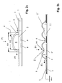
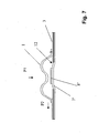
- a first embodiment of the keyboard assembly according to the invention is shown in its initial position.
- This keyboard assembly has a domed snap-action disc 1 made of metal, which is formed dome-shaped and spans the underlying space 5.
- This snap-action disc 1 is integrally connected to a web 6.
- a metal plate 3 is also provided, which has an opening 2.
- the snap-action disc 1 is connected to the plate 3 only by means of the single web 6 by Lasersch adoptedung X.
- a printed circuit board 7 is shown, on which two electrical contact surfaces 8, 9 are arranged. Only for the sake of completeness, it should be noted that the in Fig. 2a shown mutual distance between the plate 3 and the circuit board 7 need not necessarily be present, but only for the sake of better illustration in Fig. 2a has been recorded.
- the diameter D1 of the snap-action disc 1 is greater than the clear cross-section D2 of the opening 2. This ensures that in each position of the snap disc 1 together with the plate 3 components in the direction of arrow P1 below the plate 3 and the snap disc 1 are arranged, shields.
- the mutual distance between the contact surfaces 8, 9 or the printed circuit board 7 and the snap-action disk 1 is adjusted so that the deformed snap-action disk 1 rests against the contact surfaces 8, 9 or an electrically conductive connection is established between the contact surfaces 8, 9, when the "switching crack" is heard, the user receives with the "switching crack” a tangible confirmation that his keystroke has also led to the desired switching command.
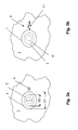
- FIG. 2b Another embodiment of the breakthrough 2 covering the snap disk 1 is shown. Just like the in Fig. 2a shown snap disk 1 also vaulted the snap disk according to Fig. 2b the breakthrough 2 completely. However, since often the plate 3 must be made relatively thick to produce a suitable shield, it may happen that one according to Fig. 2a merely dome-shaped snap-action disc 1 in the production of an electrical contact already generates the "switching crack", although no electrical contact has been made. Therefore, the snap disk 1 according to Fig. 2b provided on its zenith surface Z with a curved bead 10, the curvature of which extends into the space 5, which is spanned by the snap disk 1.
- the desired "switching crack” can be adjusted very flexibly and quickly to a given geometry of printed circuit board 7 and plate 3 by simply changing the ridge depth of the bead 10 in the space 5.
- Fig. 2b removable, that only a contact surface 8 'is arranged on the circuit board 7.
- the snap disk 1 In order to initiate an electrical contact with only one contact surface 8 ', when the snap disk 1 comes into physical contact with the contact surface 8', it is necessary for the snap disk 1 to lie “on ground”. Since the snap disk 1 according to Fig. 2b formed of metal and connected to the plate 3, which is also made of metal, this is solved in the present case, that in the embodiment according to Fig. 2b the plate 3 is "on ground".
- the circuit board 7 may be formed as a conductor foil.
- FIG. 2b shows Fig. 2b another snap-action disc 1 ', which is juxtaposed to the snap-action disc 1, and which, like the snap-action disc 1, is capable of producing a "switching crack” to create.
- this snap disk 1 ' is not used for generating a "switching crack” when performing an electrical contact, but only serves the shielding of a component 12 on the circuit board 7, which protrudes because of its height from the plate 3.
- the two snap discs 1 and 1 ' are connected by means of a common web 6 by laser welding X.
- two snap disks 1, which are each arranged above contact surfaces 8 ' can also be connected to the plate 3 by means of a common web 6. In such a case would be in Fig. 2b or 6, the component 11 is replaced by at least one contact surface 8 '.
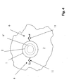
- Fig. 3b is shown another form of the web 6, with which the snap disc 1 is connected to the plate 3.
- the jaw forms a hinge 11.
- the webs 6, as in Fig. 3b and Fig. 4 shown near its free ends to the plate 3 by laser welding X connected.
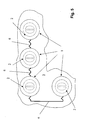
- Fig. 5 a combination of four snap discs 1 is shown, which are arranged above corresponding openings 2. All four snap discs 1 are integrally connected to each other via common webs 6 and can therefore be made in a punching pass.
- Fig. 7 instead of a printed circuit board 7, a conductor foil 7 'available.
- the conductor foil 7' projects into the space 12, which is bordered by the opening 2.
- Fig. 7 added that the execution according to Fig. 7 not necessarily conductor foils 7 'required and that the bead 10 shown in another embodiment of Fig. 7 can also be completely eliminated.
- the apertures 2 should be conical in order to reduce wear.
Landscapes
- Push-Button Switches (AREA)
- Input From Keyboards Or The Like (AREA)
Claims (9)
- Ensemble de clavier
comprenant un plateau (3) qui est formé d'un matériau conducteur de l'électricité et qui présente au moins une ouverture (2), et
comprenant un disque encliquetable cintré (1) qui présente au moins une languette (6) qui lui est connectée d'une seule pièce,
caractérisé en ce que
le disque encliquetable (1) est disposé au-dessus de l'ouverture (2) et est connecté par au moins l'une de ses languettes (6) à l'une des deux surfaces du plateau (3), de manière fixe et électriquement conductrice, et
le diamètre D1 du disque encliquetable cintré (1) est supérieur à la section transversale intérieure D2 de l'ouverture (2), celle-ci fermant complètement l'ouverture (2) dans l'état connecté au plateau (3). - Ensemble de clavier selon la revendication 1,
caractérisé en ce que
les languettes (6) ou les zones de bord du disque encliquetable (1) qui ne sont pas connectées fixement au plateau (3) s'appliquent de manière déplaçable contre la surface du plateau (3). - Ensemble de clavier selon l'une quelconque des revendications 1 ou 2,
caractérisé en ce
qu'au moins deux d'une pluralité de disques encliquetables (1) sont connectés au plateau (3) au moyen d'une languette (6) commune. - Ensemble de clavier selon l'une quelconque des revendications 1 à 3,
caractérisé en ce que
toutes les autres ouvertures (2) dans le plateau (3) sont également recouvertes par un disque encliquetable (1'). - Ensemble de clavier selon l'une quelconque des revendications 1 à 4,
caractérisé en ce que
chaque disque encliquetable (1) est connecté fixement par au moins deux languettes (6) au plateau (3), et
en ce que chaque languette (6) utilisée pour la connexion au plateau (3) présente une articulation (11), les articulations (11) opposant à une extension radiale du disque encliquetable (1) seulement une force qui est nettement inférieure à la force nécessaire pour aplatir le disque encliquetable (1). - Ensemble de clavier selon la revendication 5,
caractérisé en ce que
les languettes (6) et leurs articulations respectives (11) s'appliquent contre la surface du plateau (3) et s'écartent élastiquement, lors de l'extension radiale du disque encliquetable (1), de la mesure de cette extension radiale. - Ensemble de clavier selon l'une quelconque des revendications 1 à 6,
caractérisés en ce que
le disque encliquetable respectif (10) présente une surface de sommet Z et
en ce que la surface de sommet Z est pourvue d'une moulure cintrée (10), la courbure de la moulure (10) s'étendant dans l'espace (5) qui est couvert par la courbure du disque encliquetable (1). - Ensemble de clavier selon l'une quelconque des revendications 1 à 7,
caractérisé en ce que
chaque disque encliquetable (1) est associé à au moins un élément de contact (8, 9, 8') et en ce que les éléments de contact (8, 9, 8') sont disposés sur une carte à circuits imprimés (7) ou une feuille conductrice (7'). - Ensemble de clavier selon la revendication 8,
caractérisé en ce que
la carte à circuits imprimés (7) ou la feuille conductrice (7') pénètre au moins dans les espaces qui sont bordés par des ouvertures (2).
Applications Claiming Priority (3)
| Application Number | Priority Date | Filing Date | Title |
|---|---|---|---|
| DE102005041202 | 2005-08-31 | ||
| DE200610021474 DE102006021474A1 (de) | 2006-05-09 | 2006-05-09 | Tastaturanordnung |
| PCT/EP2006/008379 WO2007025684A1 (fr) | 2005-08-31 | 2006-08-26 | Ensemble clavier |
Publications (2)
| Publication Number | Publication Date |
|---|---|
| EP1920449A1 EP1920449A1 (fr) | 2008-05-14 |
| EP1920449B1 true EP1920449B1 (fr) | 2008-11-26 |
Family
ID=37084872
Family Applications (1)
| Application Number | Title | Priority Date | Filing Date |
|---|---|---|---|
| EP06791677A Not-in-force EP1920449B1 (fr) | 2005-08-31 | 2006-08-26 | Ensemble clavier |
Country Status (4)
| Country | Link |
|---|---|
| EP (1) | EP1920449B1 (fr) |
| AT (1) | ATE415692T1 (fr) |
| DE (1) | DE502006002220D1 (fr) |
| WO (1) | WO2007025684A1 (fr) |
Cited By (1)
| Publication number | Priority date | Publication date | Assignee | Title |
|---|---|---|---|---|
| DE102010014315A1 (de) * | 2010-04-09 | 2011-10-13 | Siemens Medical Instruments Pte. Ltd. | Hörinstrument mit Bedienvorrichtung |
Family Cites Families (3)
| Publication number | Priority date | Publication date | Assignee | Title |
|---|---|---|---|---|
| US4343973A (en) * | 1980-08-13 | 1982-08-10 | Cherry Electrical Products Corp. | Low cost electrical switch |
| JPH044338Y2 (fr) * | 1985-05-31 | 1992-02-07 | ||
| DE19851534C1 (de) * | 1998-11-09 | 2000-09-14 | Inovan Stroebe | Schnappscheiben-Metallfolie sowie Verfahren und Vorrichtung zum Herstellen einer Schnappscheiben-Metallfolie |
-
2006
- 2006-08-26 EP EP06791677A patent/EP1920449B1/fr not_active Not-in-force
- 2006-08-26 AT AT06791677T patent/ATE415692T1/de not_active IP Right Cessation
- 2006-08-26 DE DE502006002220T patent/DE502006002220D1/de active Active
- 2006-08-26 WO PCT/EP2006/008379 patent/WO2007025684A1/fr active Application Filing
Cited By (1)
| Publication number | Priority date | Publication date | Assignee | Title |
|---|---|---|---|---|
| DE102010014315A1 (de) * | 2010-04-09 | 2011-10-13 | Siemens Medical Instruments Pte. Ltd. | Hörinstrument mit Bedienvorrichtung |
Also Published As
| Publication number | Publication date |
|---|---|
| DE502006002220D1 (de) | 2009-01-08 |
| WO2007025684A1 (fr) | 2007-03-08 |
| ATE415692T1 (de) | 2008-12-15 |
| EP1920449A1 (fr) | 2008-05-14 |
Similar Documents
| Publication | Publication Date | Title |
|---|---|---|
| DE19537296C2 (de) | Wippenschaltvorrichtung für zweistufigen Betätigungshub | |
| DE2319042B2 (de) | Tastatur | |
| DE3103768A1 (de) | Tastschalteranordnung mit mindestens einem tastschalter, insbesondere tastatur | |
| DE3019886A1 (de) | Fluessigkeits- und gasdichter schiebeschalter | |
| DE3210044A1 (de) | Schalterbetaetigungsfeld | |
| DE3011674A1 (de) | Tastatur | |
| DE2515185C3 (de) | Elektrischer Schnappschalter | |
| DE3140771C2 (de) | Mehrfach-Flachschalter | |
| DE3123846A1 (de) | Tastschalteranordnung, insbesondere tastenfeld | |
| EP1920449B1 (fr) | Ensemble clavier | |
| EP3131109B1 (fr) | Touche sans espace | |
| DE2439697B2 (de) | Druckschalter | |
| DE102013018156B3 (de) | Tastatur | |
| DE3618131C2 (fr) | ||
| DE60132650T2 (de) | Verfahren zur Herstellung einer Tastatur für elektronisches Gerät | |
| DE10316934A1 (de) | Tastenblock zum Einsetzen in eine Bedienfläche eines Haushaltsgerätes | |
| EP1570631B1 (fr) | Dispositif d'entree, notamment pour un telephone portable, module comportant un tel dispositif d'entree, telephone portable et procede de production correspondant | |
| DE3441129C2 (fr) | ||
| DE3012717C2 (fr) | ||
| DE202012011448U1 (de) | Leicht montierbare, dünne Tastatur | |
| EP1482527B1 (fr) | Interrupteur à bouton poussoir | |
| DE2730659C2 (de) | Tastschalter | |
| DE102006021474A1 (de) | Tastaturanordnung | |
| DE3511342A1 (de) | Membranschalter fuer tasten und tastaturen | |
| DE3320116A1 (de) | Tastschaltvorrichtung |
Legal Events
| Date | Code | Title | Description |
|---|---|---|---|
| PUAI | Public reference made under article 153(3) epc to a published international application that has entered the european phase |
Free format text: ORIGINAL CODE: 0009012 |
|
| 17P | Request for examination filed |
Effective date: 20080228 |
|
| AK | Designated contracting states |
Kind code of ref document: A1 Designated state(s): AT BE BG CH CY CZ DE DK EE ES FI FR GB GR HU IE IS IT LI LT LU LV MC NL PL PT RO SE SI SK TR |
|
| GRAP | Despatch of communication of intention to grant a patent |
Free format text: ORIGINAL CODE: EPIDOSNIGR1 |
|
| DAX | Request for extension of the european patent (deleted) | ||
| GRAS | Grant fee paid |
Free format text: ORIGINAL CODE: EPIDOSNIGR3 |
|
| GRAA | (expected) grant |
Free format text: ORIGINAL CODE: 0009210 |
|
| AK | Designated contracting states |
Kind code of ref document: B1 Designated state(s): AT BE BG CH CY CZ DE DK EE ES FI FR GB GR HU IE IS IT LI LT LU LV MC NL PL PT RO SE SI SK TR |
|
| REG | Reference to a national code |
Ref country code: GB Ref legal event code: FG4D Free format text: NOT ENGLISH |
|
| REG | Reference to a national code |
Ref country code: CH Ref legal event code: EP |
|
| REG | Reference to a national code |
Ref country code: IE Ref legal event code: FG4D Free format text: LANGUAGE OF EP DOCUMENT: GERMAN |
|
| REF | Corresponds to: |
Ref document number: 502006002220 Country of ref document: DE Date of ref document: 20090108 Kind code of ref document: P |
|
| REG | Reference to a national code |
Ref country code: RO Ref legal event code: EPE |
|
| PG25 | Lapsed in a contracting state [announced via postgrant information from national office to epo] |
Ref country code: ES Free format text: LAPSE BECAUSE OF FAILURE TO SUBMIT A TRANSLATION OF THE DESCRIPTION OR TO PAY THE FEE WITHIN THE PRESCRIBED TIME-LIMIT Effective date: 20090308 Ref country code: LT Free format text: LAPSE BECAUSE OF FAILURE TO SUBMIT A TRANSLATION OF THE DESCRIPTION OR TO PAY THE FEE WITHIN THE PRESCRIBED TIME-LIMIT Effective date: 20081126 |
|
| NLV1 | Nl: lapsed or annulled due to failure to fulfill the requirements of art. 29p and 29m of the patents act | ||
| PG25 | Lapsed in a contracting state [announced via postgrant information from national office to epo] |
Ref country code: SI Free format text: LAPSE BECAUSE OF FAILURE TO SUBMIT A TRANSLATION OF THE DESCRIPTION OR TO PAY THE FEE WITHIN THE PRESCRIBED TIME-LIMIT Effective date: 20081126 Ref country code: PL Free format text: LAPSE BECAUSE OF FAILURE TO SUBMIT A TRANSLATION OF THE DESCRIPTION OR TO PAY THE FEE WITHIN THE PRESCRIBED TIME-LIMIT Effective date: 20081126 Ref country code: LV Free format text: LAPSE BECAUSE OF FAILURE TO SUBMIT A TRANSLATION OF THE DESCRIPTION OR TO PAY THE FEE WITHIN THE PRESCRIBED TIME-LIMIT Effective date: 20081126 Ref country code: NL Free format text: LAPSE BECAUSE OF FAILURE TO SUBMIT A TRANSLATION OF THE DESCRIPTION OR TO PAY THE FEE WITHIN THE PRESCRIBED TIME-LIMIT Effective date: 20081126 Ref country code: IS Free format text: LAPSE BECAUSE OF FAILURE TO SUBMIT A TRANSLATION OF THE DESCRIPTION OR TO PAY THE FEE WITHIN THE PRESCRIBED TIME-LIMIT Effective date: 20090326 |
|
| REG | Reference to a national code |
Ref country code: HU Ref legal event code: AG4A Ref document number: E005131 Country of ref document: HU |
|
| REG | Reference to a national code |
Ref country code: IE Ref legal event code: FD4D |
|
| PG25 | Lapsed in a contracting state [announced via postgrant information from national office to epo] |
Ref country code: EE Free format text: LAPSE BECAUSE OF FAILURE TO SUBMIT A TRANSLATION OF THE DESCRIPTION OR TO PAY THE FEE WITHIN THE PRESCRIBED TIME-LIMIT Effective date: 20081126 Ref country code: IE Free format text: LAPSE BECAUSE OF FAILURE TO SUBMIT A TRANSLATION OF THE DESCRIPTION OR TO PAY THE FEE WITHIN THE PRESCRIBED TIME-LIMIT Effective date: 20081126 Ref country code: BG Free format text: LAPSE BECAUSE OF FAILURE TO SUBMIT A TRANSLATION OF THE DESCRIPTION OR TO PAY THE FEE WITHIN THE PRESCRIBED TIME-LIMIT Effective date: 20090226 Ref country code: DK Free format text: LAPSE BECAUSE OF FAILURE TO SUBMIT A TRANSLATION OF THE DESCRIPTION OR TO PAY THE FEE WITHIN THE PRESCRIBED TIME-LIMIT Effective date: 20081126 |
|
| PG25 | Lapsed in a contracting state [announced via postgrant information from national office to epo] |
Ref country code: PT Free format text: LAPSE BECAUSE OF FAILURE TO SUBMIT A TRANSLATION OF THE DESCRIPTION OR TO PAY THE FEE WITHIN THE PRESCRIBED TIME-LIMIT Effective date: 20090427 Ref country code: CZ Free format text: LAPSE BECAUSE OF FAILURE TO SUBMIT A TRANSLATION OF THE DESCRIPTION OR TO PAY THE FEE WITHIN THE PRESCRIBED TIME-LIMIT Effective date: 20081126 Ref country code: SE Free format text: LAPSE BECAUSE OF FAILURE TO SUBMIT A TRANSLATION OF THE DESCRIPTION OR TO PAY THE FEE WITHIN THE PRESCRIBED TIME-LIMIT Effective date: 20090226 |
|
| PG25 | Lapsed in a contracting state [announced via postgrant information from national office to epo] |
Ref country code: SK Free format text: LAPSE BECAUSE OF FAILURE TO SUBMIT A TRANSLATION OF THE DESCRIPTION OR TO PAY THE FEE WITHIN THE PRESCRIBED TIME-LIMIT Effective date: 20081126 |
|
| PLBE | No opposition filed within time limit |
Free format text: ORIGINAL CODE: 0009261 |
|
| STAA | Information on the status of an ep patent application or granted ep patent |
Free format text: STATUS: NO OPPOSITION FILED WITHIN TIME LIMIT |
|
| 26N | No opposition filed |
Effective date: 20090827 |
|
| PGFP | Annual fee paid to national office [announced via postgrant information from national office to epo] |
Ref country code: HU Payment date: 20090609 Year of fee payment: 4 Ref country code: RO Payment date: 20090824 Year of fee payment: 4 |
|
| BERE | Be: lapsed |
Owner name: HARTER WERKZEUGBAU G.M.B.H. Effective date: 20090831 |
|
| PG25 | Lapsed in a contracting state [announced via postgrant information from national office to epo] |
Ref country code: MC Free format text: LAPSE BECAUSE OF NON-PAYMENT OF DUE FEES Effective date: 20090831 |
|
| PG25 | Lapsed in a contracting state [announced via postgrant information from national office to epo] |
Ref country code: BE Free format text: LAPSE BECAUSE OF NON-PAYMENT OF DUE FEES Effective date: 20090831 |
|
| PG25 | Lapsed in a contracting state [announced via postgrant information from national office to epo] |
Ref country code: GR Free format text: LAPSE BECAUSE OF FAILURE TO SUBMIT A TRANSLATION OF THE DESCRIPTION OR TO PAY THE FEE WITHIN THE PRESCRIBED TIME-LIMIT Effective date: 20090227 |
|
| PG25 | Lapsed in a contracting state [announced via postgrant information from national office to epo] |
Ref country code: AT Free format text: LAPSE BECAUSE OF NON-PAYMENT OF DUE FEES Effective date: 20090826 |
|
| PGFP | Annual fee paid to national office [announced via postgrant information from national office to epo] |
Ref country code: FR Payment date: 20100819 Year of fee payment: 5 |
|
| PG25 | Lapsed in a contracting state [announced via postgrant information from national office to epo] |
Ref country code: IT Free format text: LAPSE BECAUSE OF FAILURE TO SUBMIT A TRANSLATION OF THE DESCRIPTION OR TO PAY THE FEE WITHIN THE PRESCRIBED TIME-LIMIT Effective date: 20081126 |
|
| REG | Reference to a national code |
Ref country code: CH Ref legal event code: PL |
|
| PG25 | Lapsed in a contracting state [announced via postgrant information from national office to epo] |
Ref country code: HU Free format text: LAPSE BECAUSE OF NON-PAYMENT OF DUE FEES Effective date: 20100827 Ref country code: CH Free format text: LAPSE BECAUSE OF NON-PAYMENT OF DUE FEES Effective date: 20100831 Ref country code: LI Free format text: LAPSE BECAUSE OF NON-PAYMENT OF DUE FEES Effective date: 20100831 Ref country code: LU Free format text: LAPSE BECAUSE OF NON-PAYMENT OF DUE FEES Effective date: 20090826 |
|
| PG25 | Lapsed in a contracting state [announced via postgrant information from national office to epo] |
Ref country code: FI Free format text: LAPSE BECAUSE OF NON-PAYMENT OF DUE FEES Effective date: 20100826 |
|
| PG25 | Lapsed in a contracting state [announced via postgrant information from national office to epo] |
Ref country code: TR Free format text: LAPSE BECAUSE OF FAILURE TO SUBMIT A TRANSLATION OF THE DESCRIPTION OR TO PAY THE FEE WITHIN THE PRESCRIBED TIME-LIMIT Effective date: 20081126 |
|
| PG25 | Lapsed in a contracting state [announced via postgrant information from national office to epo] |
Ref country code: CY Free format text: LAPSE BECAUSE OF FAILURE TO SUBMIT A TRANSLATION OF THE DESCRIPTION OR TO PAY THE FEE WITHIN THE PRESCRIBED TIME-LIMIT Effective date: 20081126 |
|
| PG25 | Lapsed in a contracting state [announced via postgrant information from national office to epo] |
Ref country code: RO Free format text: LAPSE BECAUSE OF NON-PAYMENT OF DUE FEES Effective date: 20100826 |
|
| PGFP | Annual fee paid to national office [announced via postgrant information from national office to epo] |
Ref country code: FI Payment date: 20110810 Year of fee payment: 6 Ref country code: DE Payment date: 20110809 Year of fee payment: 6 Ref country code: GB Payment date: 20110809 Year of fee payment: 6 |
|
| PGRI | Patent reinstated in contracting state [announced from national office to epo] |
Ref country code: FI Effective date: 20110816 |
|
| REG | Reference to a national code |
Ref country code: FR Ref legal event code: ST Effective date: 20120430 |
|
| PG25 | Lapsed in a contracting state [announced via postgrant information from national office to epo] |
Ref country code: FR Free format text: LAPSE BECAUSE OF NON-PAYMENT OF DUE FEES Effective date: 20110831 |
|
| GBPC | Gb: european patent ceased through non-payment of renewal fee |
Effective date: 20120826 |
|
| PG25 | Lapsed in a contracting state [announced via postgrant information from national office to epo] |
Ref country code: FI Free format text: LAPSE BECAUSE OF NON-PAYMENT OF DUE FEES Effective date: 20120826 |
|
| PG25 | Lapsed in a contracting state [announced via postgrant information from national office to epo] |
Ref country code: GB Free format text: LAPSE BECAUSE OF NON-PAYMENT OF DUE FEES Effective date: 20120826 Ref country code: DE Free format text: LAPSE BECAUSE OF NON-PAYMENT OF DUE FEES Effective date: 20130301 |
|
| REG | Reference to a national code |
Ref country code: DE Ref legal event code: R119 Ref document number: 502006002220 Country of ref document: DE Effective date: 20130301 |