EP1918755A1 - Ophthalmo-Operationsmikroskop mit OCT-System - Google Patents
Ophthalmo-Operationsmikroskop mit OCT-System Download PDFInfo
- Publication number
- EP1918755A1 EP1918755A1 EP07019795A EP07019795A EP1918755A1 EP 1918755 A1 EP1918755 A1 EP 1918755A1 EP 07019795 A EP07019795 A EP 07019795A EP 07019795 A EP07019795 A EP 07019795A EP 1918755 A1 EP1918755 A1 EP 1918755A1
- Authority
- EP
- European Patent Office
- Prior art keywords
- oct
- scanning
- beam path
- surgical microscope
- ophthalmic surgical
- Prior art date
- Legal status (The legal status is an assumption and is not a legal conclusion. Google has not performed a legal analysis and makes no representation as to the accuracy of the status listed.)
- Granted
Links
Images

Classifications
-
- A—HUMAN NECESSITIES
- A61—MEDICAL OR VETERINARY SCIENCE; HYGIENE
- A61B—DIAGNOSIS; SURGERY; IDENTIFICATION
- A61B3/00—Apparatus for testing the eyes; Instruments for examining the eyes
- A61B3/10—Objective types, i.e. instruments for examining the eyes independent of the patients' perceptions or reactions
- A61B3/13—Ophthalmic microscopes
-
- A—HUMAN NECESSITIES
- A61—MEDICAL OR VETERINARY SCIENCE; HYGIENE
- A61B—DIAGNOSIS; SURGERY; IDENTIFICATION
- A61B3/00—Apparatus for testing the eyes; Instruments for examining the eyes
- A61B3/10—Objective types, i.e. instruments for examining the eyes independent of the patients' perceptions or reactions
- A61B3/102—Objective types, i.e. instruments for examining the eyes independent of the patients' perceptions or reactions for optical coherence tomography [OCT]
-
- G—PHYSICS
- G01—MEASURING; TESTING
- G01B—MEASURING LENGTH, THICKNESS OR SIMILAR LINEAR DIMENSIONS; MEASURING ANGLES; MEASURING AREAS; MEASURING IRREGULARITIES OF SURFACES OR CONTOURS
- G01B9/00—Measuring instruments characterised by the use of optical techniques
- G01B9/02—Interferometers
- G01B9/02001—Interferometers characterised by controlling or generating intrinsic radiation properties
- G01B9/02007—Two or more frequencies or sources used for interferometric measurement
-
- G—PHYSICS
- G01—MEASURING; TESTING
- G01B—MEASURING LENGTH, THICKNESS OR SIMILAR LINEAR DIMENSIONS; MEASURING ANGLES; MEASURING AREAS; MEASURING IRREGULARITIES OF SURFACES OR CONTOURS
- G01B9/00—Measuring instruments characterised by the use of optical techniques
- G01B9/02—Interferometers
- G01B9/02015—Interferometers characterised by the beam path configuration
- G01B9/02027—Two or more interferometric channels or interferometers
-
- G—PHYSICS
- G01—MEASURING; TESTING
- G01B—MEASURING LENGTH, THICKNESS OR SIMILAR LINEAR DIMENSIONS; MEASURING ANGLES; MEASURING AREAS; MEASURING IRREGULARITIES OF SURFACES OR CONTOURS
- G01B9/00—Measuring instruments characterised by the use of optical techniques
- G01B9/02—Interferometers
- G01B9/02034—Interferometers characterised by particularly shaped beams or wavefronts
- G01B9/02035—Shaping the focal point, e.g. elongated focus
-
- G—PHYSICS
- G01—MEASURING; TESTING
- G01B—MEASURING LENGTH, THICKNESS OR SIMILAR LINEAR DIMENSIONS; MEASURING ANGLES; MEASURING AREAS; MEASURING IRREGULARITIES OF SURFACES OR CONTOURS
- G01B9/00—Measuring instruments characterised by the use of optical techniques
- G01B9/02—Interferometers
- G01B9/0209—Low-coherence interferometers
- G01B9/02091—Tomographic interferometers, e.g. based on optical coherence
-
- A—HUMAN NECESSITIES
- A61—MEDICAL OR VETERINARY SCIENCE; HYGIENE
- A61B—DIAGNOSIS; SURGERY; IDENTIFICATION
- A61B90/00—Instruments, implements or accessories specially adapted for surgery or diagnosis and not covered by any of the groups A61B1/00 - A61B50/00, e.g. for luxation treatment or for protecting wound edges
- A61B90/20—Surgical microscopes characterised by non-optical aspects
-
- G—PHYSICS
- G02—OPTICS
- G02B—OPTICAL ELEMENTS, SYSTEMS OR APPARATUS
- G02B21/00—Microscopes
- G02B21/0004—Microscopes specially adapted for specific applications
- G02B21/002—Scanning microscopes
- G02B21/0024—Confocal scanning microscopes (CSOMs) or confocal "macroscopes"; Accessories which are not restricted to use with CSOMs, e.g. sample holders
- G02B21/0028—Confocal scanning microscopes (CSOMs) or confocal "macroscopes"; Accessories which are not restricted to use with CSOMs, e.g. sample holders specially adapted for specific applications, e.g. for endoscopes, ophthalmoscopes, attachments to conventional microscopes
-
- G—PHYSICS
- G02—OPTICS
- G02B—OPTICAL ELEMENTS, SYSTEMS OR APPARATUS
- G02B21/00—Microscopes
- G02B21/0004—Microscopes specially adapted for specific applications
- G02B21/002—Scanning microscopes
- G02B21/0024—Confocal scanning microscopes (CSOMs) or confocal "macroscopes"; Accessories which are not restricted to use with CSOMs, e.g. sample holders
- G02B21/0032—Optical details of illumination, e.g. light-sources, pinholes, beam splitters, slits, fibers
-
- G—PHYSICS
- G02—OPTICS
- G02B—OPTICAL ELEMENTS, SYSTEMS OR APPARATUS
- G02B21/00—Microscopes
- G02B21/0004—Microscopes specially adapted for specific applications
- G02B21/002—Scanning microscopes
- G02B21/0024—Confocal scanning microscopes (CSOMs) or confocal "macroscopes"; Accessories which are not restricted to use with CSOMs, e.g. sample holders
- G02B21/0036—Scanning details, e.g. scanning stages
-
- G—PHYSICS
- G02—OPTICS
- G02B—OPTICAL ELEMENTS, SYSTEMS OR APPARATUS
- G02B21/00—Microscopes
- G02B21/0004—Microscopes specially adapted for specific applications
- G02B21/002—Scanning microscopes
- G02B21/0024—Confocal scanning microscopes (CSOMs) or confocal "macroscopes"; Accessories which are not restricted to use with CSOMs, e.g. sample holders
- G02B21/008—Details of detection or image processing, including general computer control
Definitions
- the invention relates to an ophthalmic surgical microscope with a microscope main objective, with an observation beam passing through the microscope main objective, and with an OCT system for capturing images of an object region, the OCT system comprising an OCT scanning beam path passing over a scanning mirror arrangement is guided to the object area.
- a surgical microscope of the type mentioned is from the EP 0 697 611 B1 known.
- This surgical microscope contains an OCT system which generates a scanning beam path of short-coherent laser radiation.
- the OCT system contains an analysis unit for the evaluation of interference signals. It comprises a device for scanning the OCT scanning beam path with two scanning mirrors, which can be adjusted by two axes of movement.
- the OCT scanning beam path in the surgical microscope is coupled via a splitter mirror in the illumination beam path of the surgical microscope. He is guided with this through the microscope main objective to the object area.
- An OCT system uses optical coherence tomography to enable the noninvasive imaging and measurement of structures within a tissue.
- optical coherence tomography allows to produce slice or volume images of micrometer-resolution biological tissue.
- a corresponding OCT system comprises a source of temporally incoherent and spatially coherent light having a coherence length l c , which is supplied to a sample beam path and a reference beam path. The sample beam path is directed to the tissue to be examined. Laser radiation, which is reflected back into the sample beam path due to scattering centers in the tissue, overlaps the OCT system with laser radiation from the reference beam path. The overlay creates an interference signal. From this interference signal, the position of scattering centers for the laser radiation in the examined tissue can be determined.
- the structure of a "time-domain OCT" is for example in the US 5,321,501 with reference to Fig. 1a on Sp. 5, Z. 40 - Sp. 11, Z. 10 described.
- the optical path length of the reference beam path is continuously varied via a fast-moving reference mirror.
- the light from the sample and reference beam path is superimposed on a photodetector.
- an interference signal is produced on the photodetector.
- a “Fourier-Domain OCT” is for example in the WO 2006/10544 A1 explained.
- light from the sample beam path light is superimposed from a reference beam path.
- the light from sample and reference beam path is not fed directly to a detector, but first spectrally dissected by means of a spectrometer. The thus generated spectral intensity of the superimposed signal from the sample and reference beam path is then detected by a detector. By evaluating the detector signal, in turn, the optical path length of the sample beam path can be determined.
- the object of the invention is to provide a compact ophthalmic surgical microscope which enables the acquisition of OCT sectional images of the human eye, wherein the OCT scanning beam can be guided without loss of intensity to an OCT scanning plane.
- an ophthalmic surgical microscope of the type mentioned in the introduction in which an optical element is provided between the scanning mirror arrangement and the microscope main objective, which differs from the scanning mirror arrangement emerges OCT scanning beam path bundles and transferred to a beam path that passes through the microscope main objective.
- an ophthalmic surgical microscope of the type mentioned above in which an ophthalmoscopic magnifier is provided, which can be pivoted into and out of the observation beam path and the OCT scanning beam path.
- the ophthalmoscope magnifier makes it possible to focus the OCT scanning beam path on the background of a patient's eye, in order to scan the fundus and at the same time make it visible in the eyepiece view through the optical observation beam paths of the surgical microscope.
- the optical element between the scanning mirror arrangement and the microscope main objective is designed as a movable lens unit. In this way, different cutting planes of a human eye can be scanned with OCT radiation.
- this optical element is accommodated in a lens changing device. In this way, a fast switching back and forth between different scanning levels for OCT radiation in an object area is possible.
- the optical element is designed as a zoom system with variable focal length. In this way, a continuous variation of sectional planes examined in a patient's eye with OCT radiation is made possible.
- means for adjusting the focal length of the main objective are provided. In this way, different levels of an object area can be examined with the ophthalmic surgical microscope, without the surgical microscope having to be displaced.
- the scanning mirror arrangement for scanning the OCT scanning beam path comprises a first scanning mirror.
- a second scanning mirror is additionally provided, wherein the first scanning mirror about a first axis of rotation can be moved and the second scanning mirror can be moved about a second axis of rotation, and wherein the first axis of rotation and the second axis of rotation laterally offset at a right angle to each other.
- an object area can be scanned with a mutually perpendicular grid pattern.
- the OCT system comprises a light guide, which has a light exit section for the OCT scanning beam path, are associated with the means for moving.
- the OCT system can be adapted for the use of OCT radiation of different wavelengths.
- an ophthalmoscopic magnifier is provided in the ophthalmic surgical microscope, which can be pivoted into and out of the observation beam path and the OCT scanning beam path.
- this ophthalmoscopic magnifier is combined with a reducing lens, wherein the ophthalmoscope magnifier and reducing lens are arranged in an ophthalmoscopy attachment module which can be swiveled in and out in the OCT scanning beam path and in the observation beam path.
- the OCT system is designed in the ophthalmic surgical microscope for providing a first OCT scanning light beam having a first wavelength and for providing a second OCT scanning light beam having a second wavelength different from the first wavelength.
- a corresponding first OCT system and a corresponding second OCT system are provided which provide OCT scanning light beams of different wavelengths. In this way, body tissues of different absorption characteristics can be examined for OCT radiation with good resolution.
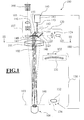
- the surgical microscope 100 in FIG. 1 has a microscope main objective 101 with an optical axis 102 and a focal plane 103.
- the microscope main objective 101 is penetrated by stereoscopic observation beam paths 105 of a binocular tube 106.
- the surgical microscope 100 has a lighting module 120 as lighting device.
- This lighting module 120 comprises a first optical waveguide 121, which provides illuminating light 122 from a light source (not shown). With the emerging from the light guide 121 illumination light 122, an adjustable field diaphragm 124 is illuminated. With a deflection mirror 123, which is arranged on the side of the microscope main objective 101 facing away from the object, the illumination light emerging from the light guide 121 is directed through the microscope main objective 101 into the object area 108.
- an ophthalmoscopy attachment module 130 with a reducing lens 131 and an ophthalmoscopic magnifier 132, which can be swiveled into and out of the stereoscopic observation beam path 105 of the surgical microscope 100 in accordance with the double arrows 133, 134.
- a first OCT system 140 is provided in the ophthalmic surgical microscope 100.
- the ophthalmic surgical microscope further includes a second OCT system shown in FIG. These OCT systems enable the acquisition of OCT images.
- the OCT system 140 of FIG. 1 comprises a unit 141 for the generation and analysis of an OCT scanning beam path 142.
- the unit 141 is integrated in the surgical microscope 100. However, it can also be arranged outside the surgical microscope 100 in a corresponding tripod console.
- the unit 141 is connected to a light guide 143, which provides the OCT scanning beam 142.
- the OCT scanning beam 142 emerging from the light guide 143 is guided with a divergent beam path onto a first scanning mirror 144 and a second scanning mirror 145 of an OCT scanning unit 146. From there it passes to an optical element in the form of a converging lens 147 in order to pass through it the microscope main objective 101.
- the OCT scanning beam 142 is collimated in an OCT scanning plane 160 in the front portion of the patient's eye 108.
- the OCT light backscattered in the OCT scanning beam path from the object area in the form of a patient's eye 108 passes back into the unit 141 via the microscope main objective 101, the converging lens 147 and the OCT scanning unit 146. There, the OCT light backscattered from the object area is detected. Scanning light with OCT radiation from a reference beam path interferes. The interference signal is detected by means of a detector and evaluated by a computer unit which determines from this signal an optical path length difference between scattering centers for OCT light in the object area and the path length of light in the reference branch.
- the converging lens 147 is assigned an adjusting mechanism 148, by means of which it can be moved in accordance with the double arrow 149.
- the OCT systems could also be designed for other operating wavelengths. Operating wavelengths can be realized in particular in the range 600 nm ⁇ ⁇ 1500 nm and are advantageous depending on the application.
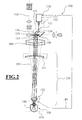
- FIG. 2 shows the ophthalmic surgical microscope 100 of FIG. 1 with the second OCT system 150 constructed and arranged in correspondence with the first OCT system 140.
- Fig. 2 Identical assemblies of the surgical microscope are provided in Fig. 2 with the same reference numerals as in Fig. 1.
- the OCT system 150 has a unit 151 for generating and analyzing an OCT scanning beam 152 of the OCT system 150. It generates 153 OCT scanning radiation 152 at the exit end of a light guide 153.
- This OCT scanning radiation 152 is like the OCT scanning radiation 142 of the OCT System 190 of FIG. 1 by an OCT scanning unit 156 with the first scanning mirror 154 and the second scanning mirror 155 is guided through the microscope main objective 101 via an optical element designed as a converging lens 157.
- FIG. 2 shows the ophthalmic surgical microscope 100 in an operating mode in which the reducing lens 131 and the ophthalmoscopic magnifier 132 of the ophthalmoscopy attachment module 130 are pivoted into the viewing beam path 205 of the surgical microscope 100. This allows examination of the background 190 of the patient's eye 108 by light which passes from the ocular fundus 190 back into the observation beam paths of the surgical microscope and with OCT scanning light.
- the condenser lens 157 focuses the OCT scanning beam and directs it to the microscope main objective 101.
- the reduction lens 131 and the ophthalmoscope magnifier 132 the OCT scanning radiation enters the patient's eye 108 and becomes in the OCT scanning plane 170 at the fundus 190 of the patient's eye 108 bundled.
- the OCT light backscattered in the OCT scanning beam path from the object area in the form of a patient's eye 108 is guided back into the unit 151 for generating and analyzing an OCT scanning beam path via the microscope main objective 101, the converging lens 157 and the OCT scanning unit 156.
- the backscattered from the object area OCT scanning light is in turn interfered with OCT radiation from a reference beam path.
- the interference signal is also detected in the OCT system 150 by means of a detector and evaluated by a computer unit which determines from this signal an optical path length difference between scattering centers for OCT light in the object area and the path length of light in the reference branch.
- the converging lens 157 is associated with an adjusting mechanism 157, by means of which it can be moved in accordance with the double arrow 159. In this way, a focal plane can also be set for the OCT scanning radiation from the OCT system 150.
- the optical path length of the OCT scanning beam path in the operating mode of the ophthalmic surgical microscope 100 shown in FIG. 2 is longer than in the operating mode of FIG. 1. This requires an adjustment of the optical path length in the reference beam path of the OCT system 150.
- a coupling 180 of Ophthalmoskopierlupe 132 and OCT system 150 is provided, which causes the pivoting of the Ophthalmoskopierlupe 132 in the observation and OCT beam path, the optical path length of the reference beam path in the OCT system is increased according to a certain value.
- This value is preferably kept adjustable.
- a set value is favorably based on the average length of a patient's eye.
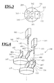
- FIG. 3 is a section along the line III-III of FIG. 1. This figure illustrates the course of the stereoscopic observation beam paths 105, 205 of the surgical microscope 100 of FIG. 1.
- the microscope main objective 101 is penetrated by two stereoscopic sub-strands 105, 205 ,
- the optical axis 102 of the microscope main objective lies in its center 310.
- the OCT scanning beam path 142 of the OCT system 140 of FIG. 1 passes through the microscope main objective 101 in the region 301. In the region 302, it is transmitted from the OCT scanning beam path 152 of the OCT System 150 of FIG. 2 and in the area 303 of the illumination light 122 passes through.
- FIG. 4 shows the first OCT system 140 and the second OCT system 150 in the surgical microscope 100 from FIG. 1 and FIG. 2.
- the same reference numerals as in Fig. 1 and Fig. 2 are used.
- the first scanning mirror 144, 154 and the second scanning mirror 145, 155 of the OCT systems 140, 150 are rotatably arranged about two mutually perpendicular axes 405, 406, 407 and 408 by means of actuators 401, 402, 403, 404. This makes possible, the OCT scanning beam paths 142, 152 are independently scanned across a plane.
- the OCT scanning beam 142 of the first OCT system 140 is guided to the microscope main lens 101 via the converging lens 147.
- the OCT scanning beam 152 of the second OCT system 150 passes through the main objective lens 101 via the converging lens 157.
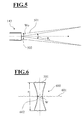
- Fig. 5 shows the front portion 502 of the light guide 143 of FIG. 1.
- the diameter d 1 of the fiber core of the optical fiber 143 satisfies the relationship d 1 2 ⁇ 2.4 ⁇ ⁇ 1 2 ⁇ ⁇ NA 1 .
- NA 1 is the numerical aperture of the front face of the lightguide.
- the diameter d of the fiber core of the optical waveguide 122 is preferably in the range 5 ⁇ m ⁇ d ⁇ 10 ⁇ m.
- the front surface 502 of the light guide 143 is imaged via the scanning mirrors 144 and 145 in the surgical microscope 100 of FIG. 1, the converging lens 147 through the microscope main objective in an OCT scanning plane.
- FIG. 6 shows the course of the intensity distribution of the OCT scanning light beam 501 perpendicular to the OCT scanning plane 601.
- the intensity distribution of the OCT scanning radiation has a smallest constriction.
- the diameter of the OCT scanning beam path increases. Since the OCT scanning light beam 501 exits the light guide 143 of FIG. 5 with an approximately gaussian radiation profile, the condenser lens 147 and the microscope main objective 101 of the surgical microscope 100 of FIG.
- This Gauss bundle 600 is represented by the confocal parameter z 1 as a measure of the longitudinal extent of the waist of the Gauss bundle, and the waist parameters W 1, A as a measure of the diameter of the smallest constriction 602 of the OCT.
- ⁇ 1 is the wavelength of the OCT Abtastlichtstrahls.
- W 1 . A ⁇ 1 ⁇ W 1 .
- ⁇ 1 is the enlargement or reduction parameter of the above-mentioned geometrical mapping of the exit end of optical fiber 143 of FIG. 1 in the OCT scanning plane.
- the size of structures which can be resolved with the OCT scanning light beam 501 is determined by its diameter in the OCT scanning plane 601, ie by the waist parameter W 1 . If, for example, an application requires a lateral resolution of the OCT system in the surgical microscope of approximately 40 ⁇ m, the cross section of the OCT scanning light beam 501 in the OCT scanning plane must be approximately 20 ⁇ m, according to the Nyquist theorem. For a given resolution of the OCT system 140, the magnification of the optical image in the OCT beam path and the diameter of the fiber core in the optical waveguide 143 must therefore be selected appropriately for a given resolution ⁇ 1 for the OCT scanning light beam 143 from FIG.
- the confocal parameter z 1 as a measure of the longitudinal extent of the waist of the Gauss bundle determines the axial depth range from which light scattered back in the OCT scanning beam 143 of FIG. 1 can be detected: the smaller the confocal parameter z 1 , the greater the Loss of the OCT system at lateral resolution upon removal of an OCT scan scanned object from the OCT scan plane 601, since the location of scattering centers can only be located within the "funnel" defined by the waist parameter W 1 and the confocal parameter z 1 ,
- the axial resolution of an OCT system is limited by the coherence length l c of the light of the light source used in the OCT system, and on the other hand, the lateral resolution of the OCT system decreases when its depth stroke exceeds the confocal parameter, setting the confocal parameter z 1 on the coherence length l c of the light source used in the OCT system low.
- the possible lateral resolution of the OCT system of FIG. 1 then results, since the wavelength ⁇ 1 and the Rayleigh parameter z 1 determine the waist parameter W 1, A.
- the optical units in the OCT scanning beam path 143 from FIG. 1 and the dimensioning of the fiber core of light guide 143 are then to be selected so that the relevant waist parameter is realized.
- the converging lens 147 in the surgical microscope 100 is preferably adjusted so that the focal plane 170 of the microscope main objective 101 for the visible spectral range and OCT scanning plane 160 of the OCT system 140 coincide. Then, the waist 502 of the OCT scanning beam shown in Fig. 5 lies in the focal plane of the operation microscope.
- the diameter d 2 of the fiber core of the optical fiber 153 therefore satisfies the relationship: d 2 2 ⁇ 2.4 ⁇ ⁇ 2 2 ⁇ ⁇ NA 2 .
- NA 2 is the numerical aperture of the front surface of the light guide 153.
- W 2 . A ⁇ 2 ⁇ W 2 .
- ⁇ 2 is the magnification or reduction parameter of the geometric image of the exit end of light guide 153 of FIG. 2 in the OCT scan plane 170.
- ⁇ 2 is determined by the focal length of the condenser lens 157 of FIG. 2, the focal length of the main microscope body 101 1, and by the reducing lens 131, the ophthalmoscope magnifier 132, and the cornea and lens of the patient's eye 108.
- the converging lens 157 is preferably set so that when the optical observation beam path through the main microscope objective 101 images the ocular fundus 190 of the patient's eye 108, the OCT scanning plane 170 for the OCT system 150 in the surgical microscope 100 coincides with the ocular fundus 190.
- this offset is not greater than the confocal parameter z of the OCT scanning light beam in the area of the OCT scanning plane.
- the depth of travel for the OCT system in the object area can be maximized.
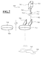
- FIG. 7 Shown in FIG. 7 is a modified embodiment for an OCT system that may be used in the ophthalmic surgical microscope 100 of FIGS. 1 and 2.
- the OCT system 700 comprises according to the OCT system 140 of FIG. 1 a unit 701 for the generation and analysis of an OCT scanning beam path 702.
- the unit 701 is designed so that OCT scanning beam paths with different wavelengths can be generated and evaluated .
- a controller 703 is provided for adjusting the wavelength of the OCT system 700 .
- the OCT scanning beam 702 exits from a light guide 704 connected to the unit 701. It arrives at two scanning mirrors 705, 706 which are movable by means of drives not shown in such a way that an object region 708 can be scanned in an OCT scanning plane 707.
- a magnification changer 709 is provided as the lens changing device, which contains converging lenses of different refractive power 710, 711. These converging lenses 710, 711 can be swung in and out of the OCT scanning beam 702. Furthermore, a drive unit 712 is associated with the light guide 704, which makes it possible to move the light guide exit end 713 in correspondence with the double arrows 714 in order in this way to be able to vary the position of the OCT scanning plane 707 in the object area.
- the OCT scanning beam 707 passes through the converging lens 709, which bundles the scanning beam and forwards to the microscope main objective of the corresponding operating microscope.
- Fig. 8 shows another embodiment of an OCT system for an ophthalmic surgical microscope.
- the OCT system like the OCT system 700, has a unit 801 for the generation and analysis of an OCT scanning beam path 802 exiting the one light guide 803.
- the OCT scanning beam 802 exiting the optical fiber exit end 804 is guided via a corresponding scanning mirror system 805 through an adjustable power lens unit 806 which acts as a zoom system.
- an adjustable power lens unit 806 acts as a zoom system.
- FIG. 1 Another modified embodiment of the surgical microscope 100 explained with reference to FIG. 1 includes a focusable microscope main objective with adjustable focal length. This measure also makes it possible to shift an OCT scanning plane and to change the geometric image of the light guide exit end into the OCT scanning plane.
Landscapes
- Health & Medical Sciences (AREA)
- Physics & Mathematics (AREA)
- Life Sciences & Earth Sciences (AREA)
- General Physics & Mathematics (AREA)
- General Health & Medical Sciences (AREA)
- Engineering & Computer Science (AREA)
- Ophthalmology & Optometry (AREA)
- Heart & Thoracic Surgery (AREA)
- Medical Informatics (AREA)
- Molecular Biology (AREA)
- Surgery (AREA)
- Animal Behavior & Ethology (AREA)
- Biomedical Technology (AREA)
- Public Health (AREA)
- Veterinary Medicine (AREA)
- Biophysics (AREA)
- Nuclear Medicine, Radiotherapy & Molecular Imaging (AREA)
- Radiology & Medical Imaging (AREA)
- Eye Examination Apparatus (AREA)
- Investigating Or Analysing Materials By Optical Means (AREA)
- Microscoopes, Condenser (AREA)
Abstract
Description
- Die Erfindung betrifft ein Ophthalmo-Operationsmikroskop mit einem Mikroskop-Hauptobjektiv, mit einem Beobachtungsstrahlengang, der das Mikroskop-Hauptobjektiv durchsetzt, und mit einem OCT-System zur Aufnahme von Bildern eines Objektbereichs, wobei das OCT-System einen OCT-Abtaststrahlengang umfasst, der über eine Scanspiegelanordnung zum Objektbereich geführt ist.
- Ein Operationsmikroskop der eingangs genannten Art ist aus der
EP 0 697 611 B1 bekannt. Dieses Operationsmikroskop enthält ein OCT-System, das einen Abtaststrahlengang aus kurzkohärenter Laserstrahlung erzeugt. Das OCT-System enthält eine Analyseeinheit zur Auswertung von Interferenzsignalen. Es umfasst eine Einrichtung zum Scannen des OCT-Abtaststrahlengangs mit zwei Scanspiegeln, die um zwei Bewegungsachsen verstellt werden können. Der OCT-Abtaststrahlengang in dem Operationsmikroskop ist über einen Teilerspiegel in den Beleuchtungsstrahlengang des Operationsmikroskops eingekoppelt. Er wird mit diesem durch das Mikroskop-Hauptobjektiv hindurch zum Objektbereich gelenkt. - Ein OCT-System erlaubt mittels optischer Kohärenztomographie die nichtinvasive Darstellung und Messung von Strukturen innerhalb eines Gewebes. Als optisches bildgebendes Verfahren ermöglicht die optische Kohärenztomographie insbesondere Schnitt- oder Volumenbilder von biologischem Gewebe mit Mikrometerauflösung zu erzeugen. Ein entsprechendes OCT-System umfasst eine Quelle für zeitlich inkohärentes und räumlich kohärentes Licht mit einer Kohärenzlänge lc, die einem Probenstrahlengang und einem Referenzstrahlengang zugeführt wird. Der Probenstrahlengang ist auf das zu untersuchende Gewebe gerichtet. Laserstrahlung, die aufgrund von Streuzentren im Gewebe in den Probenstrahlengang zurückgestrahlt wird, überlagert das OCT-System mit Laserstrahlung aus dem Referenzstrahlengang. Durch die Überlagerung entsteht ein Interferenzsignal. Aus diesem Interferenzsignal lässt sich die Position von Streuzentren für die Laserstrahlung im untersuchten Gewebe bestimmen.
- Für OCT-Systeme ist das Bauprinzip des "Time-Domain OCT" und des "Fourier-Domain OCT" bekannt.
- Der Aufbau eines "Time-Domain OCT" ist beispielsweise in der
US 5,321,501 anhand von Fig. 1a auf Sp. 5, Z. 40 - Sp. 11, Z. 10 beschrieben. In einem solchen System wird die optische Weglänge des Referenzstrahlenganges über einen schnell beweglichen Referenzspiegel fortlaufend variiert. Das Licht aus Proben- und Referenzstrahlengang wird auf einem Photodetektor überlagert. Wenn die optischen Weglängen von Proben- und Referenzstrahlengang übereinstimmen, entsteht auf dem Photodetektor ein Interferenzsignal. - Ein "Fourier-Domain OCT" ist beispielsweise in der
WO 2006/10544 A1 - Aufgabe der Erfindung ist es, ein kompakt aufgebautes Ophthalmo-Operationsmikroskop bereitzustellen, das die Aufnahme von OCT-Schnittbildern des menschlichen Auges ermöglicht, wobei der OCT-Abtaststrahlengang ohne Intensitätsverluste zu einer OCT-Abtastebene geführt werden kann.
- Diese Aufgabe wird durch ein Ophthalmo-Operationsmikroskop der eingangs genannten Art gelöst, bei dem zwischen der Scanspiegelanordnung und dem Mikroskop-Hauptobjektiv ein Optikelement vorgesehen ist, das den aus der Scanspiegelanordnung austretenden OCT-Abtaststrahlengang bündelt und in einen Strahlengang überführt, der das Mikroskop-Hauptobjektiv durchsetzt.
- Die Aufgabe wird auch durch ein Ophthalmo-Operationsmikroskop der eingangs genannten Art gelöst, bei dem eine Ophthalmoskopierlupe vorgesehen ist, die in den Beobachtungsstrahlengang und den OCT-Abtaststrahlengang ein- und ausgeschwenkt werden kann. Die Ophthalmoskopierlupe ermöglicht, den OCT-Abtaststrahlengang auf dem Hintergrund eines Patientenauges zu bündeln, um den Augenhintergrund abzutasten und gleichzeitig diesen im Okulareinblick durch die optischen Beobachtungsstrahlengänge des Operationsmikroskops sichtbar zu machen.
- In Weiterbildung der Erfindung ist das Optikelement zwischen Scanspiegelanordnung und Mikroskop-Hauptobjektiv als bewegliche Linseneinheit ausgeführt. Auf diese Weise können unterschiedliche Schnittebenen eines menschlichen Auges mit OCT-Strahlung abgetastet werden.
- In Weiterbildung der Erfindung ist dieses Optikelement in einer Linsenwechseleinrichtung aufgenommen. Auf diese Weise wird ein schnelles Hin- und Herschalten zwischen unterschiedlichen Abtastebenen für OCT-Strahlung in einem Objektbereich möglich.
- In Weiterbildung der Erfindung ist das Optikelement als Zoomsystem mit variabler Brennweite ausgeführt. Auf diese Weise wird eine stufenlose Variation von in einem Patientenauge untersuchten Schnittebenen mit OCT-Strahlung ermöglicht.
- In Weiterbildung der Erfindung sind Mittel zur Einstellung der Brennweite des Hauptobjektivs vorgesehen. Auf diese Weise können mit dem Ophthalmo-Operationsmikroskop unterschiedliche Ebenen eines Objektbereichs untersucht werden, ohne dass dabei das Operationsmikroskop verlagert werden muss.
- In Weiterbildung der Erfindung umfasst die Scanspiegelanordnung für das Scannen des OCT-Abtaststrahlengangs einen ersten Scanspiegel. Vorzugsweise ist zusätzlich ein zweiter Scanspiegel vorgesehen, wobei der erste Scanspiegel um eine erste Drehachse bewegt werden kann und der zweite Scanspiegel um eine zweite Drehachse bewegt werden kann, und wobei die erste Drehachse und die zweite Drehachse seitlich versetzt in einem rechten Winkel zueinander stehen. Auf diese Weise kann ein Objektbereich mit einem zueinander senkrecht verlaufenden Rastermuster abgetastet werden.
- In Weiterbildung der Erfindung umfasst das OCT-System einen Lichtleiter, der einen Lichtaustrittsabschnitt für den OCT-Abtaststrahlengang hat, dem Mittel zum Bewegen zugeordnet sind. Auf diese Weise kann das OCT-System für die Verwendung von OCT-Strahlung unterschiedlicher Wellenlänge angepasst werden.
- In Weiterbildung der Erfindung ist bei dem Ophthalmo-Operationsmikroskop eine Ophthalmoskopierlupe vorgesehen, die in den Beobachtungsstrahlengang und den OCT-Abtaststrahlengang ein- und ausgeschwenkt werden kann. Vorzugsweise wird diese Ophthalmoskopierlupe mit einer Reduzierlinse kombiniert, wobei Ophthalmoskopierlupe und Reduzierlinse in einem Ophthalmoskopie-Vorsatzmodul angeordnet sind, welches in den OCT-Abtaststrahlengang und in den Beobachtungsstrahlengang ein- und ausgeschwenkt werden kann. Auf diese Weise kann mit dem Ophthalmo-Operationsmikroskop sowohl der vordere Abschnitt eines Patientenauges als auch dessen Augenhintergrund mit OCT-Strahlung untersucht werden.
- In Weiterbildung der Erfindung ist das OCT-System im Ophthalmo-Operationsmikroskop für das Bereitstellen eines ersten OCT-Abtastlichtstrahls mit einer ersten Wellenlänge und für das Bereitstellen eines zweiten OCT-Abtastlichtstrahls mit einer von der ersten Wellenlänge verschiedenen zweiten Wellenlänge ausgelegt. Vorzugsweise sind ein entsprechendes erstes OCT-System und ein entsprechendes zweites OCT-System vorgesehen, die OCT-Abtastlichtstrahlen unterschiedlicher Wellenlänge bereitstellen. Auf diese Weise kann Körpergewebe unterschiedlicher Absorptionscharakteristik für OCT-Strahlung mit guter Auflösung untersucht werden.
- Vorteilhafte Ausführungsformen der Erfindung sind in den Figuren dargestellt und werden nachfolgend beschrieben.
- Es zeigen:
- Fig. 1
- ein Ophthalmo-Operationsmikroskop mit Ophthalmoskopie-Vorsatzmodul und einem ersten OCT-System;
- Fig. 2
- das Ophthalmo-Operationsmikroskop aus Fig. 1 mit einem zweiten OCT-System, wobei das Ophthalmoskopie-Vorsatzmodul in den Beobachtungsstrahlengang des Ophthalmo-Operationsmikroskops eingeschwenkt ist;
- Fig. 3
- einen Schnitt des Mikroskop-Hauptobjektivs entlang der Linie III - III aus Fig. 1;
- Fig. 4
- einen Abschnitt des Ophthalmo-Operationsmikroskops mit einem ersten und einem zweiten OCT-System;
- Fig. 5
- eine Intensitätsverteilung des aus dem Lichtleiter des OCT-Systems im Operationsmikroskop austretenden OCT-Abtastlichtstrahls; und
- Fig.6
- eine Intensitätsverteilung des OCT-Abtastlichtstrahls in der OCT-Abtastebene im Objektbereich des Operationsmikroskops.
- Fig. 7 und Fig. 8
- modifizierte Ausführungsformen für ein OCT-System in dem Operationsmikroskop.
- Das Operationsmikroskop 100 in Fig. 1 hat ein Mikroskop-Hauptobjektiv 101 mit einer optischen Achse 102 sowie einer Fokusebene 103. Das Mikroskop-Hauptobjektiv 101 wird von stereoskopischen Beobachtungsstrahlengängen 105 eines Binokulartubus 106 durchsetzt.
- Zur Beleuchtung des Objektbereichs in Form eines Patientenauges 108 hat das Operationsmikroskop 100 als Beleuchtungseinrichtung ein Beleuchtungsmodul 120. Dieses Beleuchtungsmodul 120 umfasst einen ersten Lichtleiter 121, der Beleuchtungslicht 122 von einer nicht weiter dargestellten Lichtquelle bereitstellt. Mit dem aus dem Lichtleiter 121 austretenden Beleuchtungslicht 122 wird eine verstellbare Leuchtfeldblende 124 ausgeleuchtet. Mit einem Umlenkspiegel 123, der auf der objektabgewandten Seite des Mikroskop-Hauptobjektivs 101 angeordnet ist, wird das aus dem Lichtleiter 121 austretende Beleuchtungslicht durch das Mikroskop-Hauptobjektiv 101 hindurch in den Objektbereich 108 gelenkt.
- Dem Ophthalmo-Operationsmikroskop 100 ist ein Ophthalmoskopie-Vorsatzmodul 130 mit einer Reduzierlinse 131 und einer Ophthalmoskopierlupe 132 zugeordnet, die in den stereoskopischen Beobachtungsstrahlengang 105 des Operationsmikroskops 100 entsprechend der Doppelpfeile 133, 134 ein- und ausgeschwenkt werden können.
- In dem Ophthalmo-Operationsmikroskop 100 ist ein erstes OCT-System 140 vorgesehen. Das Ophthalmo-Operationsmikroskop enthält weiter ein zweites OCT-System, das in Fig. 2 gezeigt ist. Diese OCT-Systeme ermöglichen die Aufnahme von OCT-Bildem.
- Das OCT-System 140 aus Fig. 1 umfasst eine Einheit 141 für die Erzeugung und Analyse eines OCT-Abtaststrahlengangs 142. Die Einheit 141 ist in das Operationsmikroskop 100 integriert. Sie kann aber auch außerhalb des Operationsmikroskops 100 in einer entsprechenden Stativkonsole angeordnet werden. Die Einheit 141 ist mit einem Lichtleiter 143 verbunden, der den OCT-Abtaststrahlengang 142 bereitstellt.
- Der aus dem Lichtleiter 143 austretende OCT-Abtaststrahlengang 142 wird mit divergentem Strahlengang auf einen ersten Scanspiegel 144 und einen zweiten Scanspiegel 145 einer OCT-Scaneinheit 146 geführt. Von dort gelangt er zu einem Optikelement in Form einer Sammellinse 147, um darauf das Mikroskop-Hauptobjektiv 101 zu durchsetzen. Der OCT-Abtaststrahlengang 142 wird in einer OCT-Abtastebene 160 im Frontabschnitt des Patientenauges 108 gebündelt.
- Das in den OCT-Abtaststrahlengang aus dem Objektbereich in Form eines Patientenauges 108 zurückgestreute OCT-Licht gelangt über das Mikroskop-Hauptobjektiv 101, die Sammellinse 147 und die OCT-Scaneinheit 146 zurück in die Einheit 141. Dort wird das aus dem Objektbereich zurückgestreute OCT-Abtastlicht mit OCT-Strahlung aus einem Referenzstrahlengang interferiert. Das Interferenzsignal wird mittels eines Detektors erfasst und durch eine Rechnereinheit ausgewertet, die aus diesem Signal eine optische Weglängendifferenz zwischen Streuzentren für OCT-Licht im Objektbereich und der Weglänge von Licht im Referenzzweig bestimmt.
- Zur Einstellung der OCT-Abtastebene 160 ist der Sammellinse 147 ein Verstellmechanismus 148 zugeordnet, mittels dessen diese entsprechend dem Doppelpfeil 149 bewegt werden kann.
- Das erste OCT-System 140 arbeitet bei einer Wellenlänge von λ = 1310nm. Das zweite OCT-System im Ophthalmo-Operationsmikroskop 100 ist entsprechend dem ersten OCT-System 140 aufgebaut, hat jedoch eine Arbeitswellenlänge von λ = 800nm. Selbstverständlich könnten die OCT-Systeme auch für andere Arbeitswellenlängen ausgelegt werden. Arbeitswellenlängen lassen sich insbesondere im Bereich 600nm < λ < 1500nm realisieren und sind je nach Applikation vorteilhaft.
- Die Fig. 2 zeigt das Ophthalmo-Operationsmikroskop 100 aus Fig. 1 mit dem zweiten OCT-System 150, das entsprechend dem ersten OCT-System 140 darin aufgebaut und angeordnet ist.
- Identische Baugruppen des Operationsmikroskops sind dabei in Fig. 2 mit denselben Bezugszeichen wie in Fig. 1 versehen.
- Das OCT-System 150 hat eine Einheit 151 zur Erzeugung und Analyse eines OCT-Abtaststrahlengangs 152 des OCT-Systems 150. Es generiert am Austrittsende eines Lichtleiters 153 OCT-Abtaststrahlung 152. Diese OCT-Abtaststrahlung 152 ist wie die OCT-Abtaststrahlung 142 des OCT-Systems 190 aus Fig. 1 durch eine OCT-Scaneinheit 156 mit erstem Scanspiegel 154 und zweitem Scanspiegel 155 über ein als Sammellinse 157 ausgebildetes Optikelement durch das Mikroskop-Hauptobjektiv 101 geführt.
- Fig. 2 zeigt das Ophthalmo-Operationsmikroskop 100 in einem Betriebsmodus, bei dem die Reduzierlinse 131 und die Ophthalmoskopierlupe 132 des Ophthalmoskopie-Vorsatzmoduls 130 in den Beobachtungsstrahlengang 205 des Operationsmikroskops 100 eingeschwenkt ist. Dies ermöglicht eine Untersuchung des Hintergrundes 190 des Patientenauges 108 durch Licht, das vom Augenhintergrund 190 zurück in die Beobachtungsstrahlengänge des Operationsmikroskops gelangt und mit OCT-Abtastlicht.
- Die Sammellinse 157 bündelt den OCT-Abtaststrahlengang und lenkt ihn zum Mikroskop-Hauptobjektiv 101. Durch das Mikroskop-Hauptobjektiv 101, die Reduzierlinse 131 und die Ophthalmoskopierlupe 132 gelangt die OCT-Abtaststrahlung in das Patientenauge 108 und wird in der OCT-Abtastebene 170 am Augenhintergrund 190 des Patientenauges 108 gebündelt.
- Das in den OCT-Abtaststrahlengang aus dem Objektbereich in Form eines Patientenauges 108 zurückgestreute OCT-Licht wird über das Mikroskop-Hauptobjektiv 101, die Sammellinse 157 und die OCT-Scaneinheit 156 zurück in die Einheit 151 zur Erzeugung und Analyse eines OCT-Abtaststrahlengangs geführt. Dort wird das aus dem Objektbereich zurückgestreute OCT-Abtastlicht wiederum mit OCT-Strahlung aus einem Referenzstrahlengang interferiert. Wie bei dem OCT-System 140 wird auch im OCT-System 150 das Interferenzsignal mittels eines Detektors erfasst und durch eine Rechnereinheit ausgewertet, die aus diesem Signal eine optische Weglängendifferenz zwischen Streuzentren für OCT-Licht im Objektbereich und der Weglänge von Licht im Referenzzweig bestimmt.
- Der Sammellinse 157 ist ein Verstellmechanismus 157 zugeordnet, mittels dessen diese entsprechend dem Doppelpfeil 159 bewegt werden kann. Auf diese Weise kann auch für die OCT-Abtaststrahlung aus dem OCT-System 150 eine Fokusebene eingestellt werden.
- Die optische Weglänge des OCT-Abtaststrahlengangs in dem in Fig. 2 gezeigten Betriebsmodus des Ophthalmo-Operationsmikroskops 100 ist länger als in dem Betriebsmodus nach Fig. 1. Dies macht eine Anpassung der optischen Weglänge im Referenzstrahlengang des OCT-Systems 150 erforderlich. Dazu ist eine Kopplung 180 von Ophthalmoskopierlupe 132 und OCT-System 150 vorgesehen, die bewirkt, dass bei Einschwenken der Ophthalmoskopierlupe 132 in den Beobachtungs- und OCT-Strahlengang die optische Weglänge des Referenzstrahlenganges im OCT-System entsprechend einem bestimmten Wert vergrößert wird. Dieser Wert ist vorzugsweise einstellbar gehalten. Ein festgelegter Wert orientiert sich günstigerweise an der Durchschnittslänge eines Patientenauges.
- Fig. 3 ist ein Schnitt entlang der Linie III - III aus Fig. 1. Diese Figur erläutert den Verlauf der stereoskopischen Beobachtungsstrahlengänge 105, 205 des Operationsmikroskops 100 aus Fig. 1. Das Mikroskop-Hauptobjektiv 101 wird von zwei stereoskopischen Teilstrählengängen 105, 205 durchsetzt. Die optische Achse 102 des Mikroskop-Hauptobjektivs liegt in dessen Zentrum 310. Der OCT-Abtaststrahlengang 142 des OCT-Systems 140 aus Fig. 1 durchsetzt das Mikroskop-Hauptobjektiv 101 im Bereich 301. Im Bereich 302 wird es vom OCT-Abtaststrahlengang 152 des OCT-Systems 150 aus Fig. 2 und im Bereich 303 von dem Beleuchtungslicht 122 durchsetzt.
- Fig. 4 zeigt das erste OCT-System 140 und das zweite OCT-System 150 im Operationsmikroskop 100 aus Fig. 1 bzw. Fig. 2. Der Wellenlängenbereich der OCT-Abtaststrahlengänge der beiden OCT-Systeme 140, 150 ist allerdings unterschiedlich: Das erste OCT-System basiert auf OCT-Abtaststrahlung der Wellenlänge λ1 = 1310nm. Das zweite OCT-System 320 arbeitet mit OCT-Abtaststrahlung der Wellenlänge λ2 = 800 nm. Zur Bezeichnung der Baugruppen der OCT-Systeme 140 und 150 in Fig. 4 sind die gleichen Bezugszeichen wie in Fig. 1 bzw. Fig. 2 verwendet.
- Der erste Scanspiegel 144, 154 und der zweite Scanspiegel 145, 155 der OCT-Systeme 140, 150 sind mittels Stellantrieben 401, 402, 403, 404 um zwei zueinander senkrecht verlaufende Achsen 405, 406, 407 und 408 drehbeweglich angeordnet. Dies ermöglicht, die OCT-Abtaststrahlengänge 142, 152 unabhängig voneinander über eine Ebene zu scannen.
- Der OCT-Abtaststrahlengang 142 des ersten OCT-Systems 140 wird über die Sammellinse 147 zu dem Mikroskop-Hauptobjektiv 101 geführt. Der OCT-Abtaststrahlengang 152 des zweiten OCT-Systems 150 gelangt über die Sammellinse 157 durch das Mikroskop-Hauptobjektiv 101.
- Fig. 5 zeigt den Frontabschnitt 502 des Lichtleiters 143 aus Fig. 1. Der Lichtleiter 143 wirkt für Licht der Wellenlänge λ1 = 1310nm als Monomodenfaser. Der Durchmesser d1 des Faserkerns des Lichtleiters 143 genügt der Beziehung

wobei NA1 die numerische Apertur der Frontfläche des Lichtleiters ist. Vorzugsweise liegt der Durchmesser d des Faserkerns des Lichtleiters 122 im Bereich 5µm < d < 10µm. In diesem Parameterbereich führt der Lichtleiter 143 das Licht mit gaussförmigen Wellenmoden. Aus dem Lichtleiter 143 tritt der OCT-Abtastlichtstrahl 501 mit einem näherungsweise gaussförmigen Strahlungsprofil aus, das durch einen Taillenparamter W1 und einem Öffnungsparameter θ1 charakterisiert ist, wobei gilt:
- Für einen Faserkerndurchmesser von d1 = 10µm, einen Wellenlänge λ1 = 1310nm ergibt sich damit als Maß für die Strahldivergenz ein Öffnungswinkel von θ1 ≈ 0,0827 rad.
- Die Frontfläche 502 des Lichtleiters 143 wird über die Scanspiegel 144 und 145 im Operationsmikroskop 100 aus Fig. 1, die Sammellinse 147 durch das Mikroskop-Hauptobjektiv in eine OCT-Abtastebene abgebildet.
- Die Fig. 6 zeigt den Verlauf der Intensitätsverteilung des OCT-Abtastlichtstrahls 501 senkrecht zur OCT-Abtastebene 601. In der OCT-Abtastebene 601 hat die Intensitätsverteilung der OCT-Abtaststrahlung eine kleinste Einschnürung. Außerhalb der OCT-Abtastebene nimmt der Durchmesser des OCT-Abtaststrahlengangs zu. Da der OCT-Abtastlichtstrahl 501 aus dem Lichtleiter 143 aus Fig. 5 mit einem näherungsweise gaussförmigen Strahlungsprofil austritt, bewirken die Sammellinse 147 und das Mikroskop-Hauptobjektiv 101 des Operationsmikroskops 100 aus Fig. 1 für den OCT-Abtastlichtstrahl im Bereich der OCT-Abtastebene 160 ein sogenanntes Gaussbündel 600 des OCT-Abtastlichtstrahls 501. Dieses Gaussbündel 600 ist durch den konfokalen Parameter z1 als Maß für die longitudinale Ausdehnung der Taille des Gaussbündels, sowie den Taillenparameter W1,A als Mass für den Durchmesser der kleinsten Einschnürung 602 des OCT-Abtastlichtstrahls 501 in der OCT-Abtastebene, d.h. für den Durchmesser von dessen Taille charakterisiert, wobei gilt:

dabei ist λ1 die Wellenlänge des OCT-Abtastlichtstrahls. Zwischen dem Taillenparametern W1,A des Gaussbündels 600 und dem Taillenparameter W1 des in Fig. 5 gezeigten, aus dem Lichtleiter 143 austretenden Abtastlichtstrahls 501 gilt die folgende Beziehung: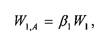
wobei β1 der Vergrößerungs- bzw. Verkleinerungsparameter der oben erwähnten geometrischen Abbildung des Austrittsendes von Lichtleiter 143 aus Fig. 1 in der OCT-Abtastebene ist. β1 ist mit der Brennweite f147 der Sammellinse 147 aus Fig. 1 und der Brennweite f2 des Mikroskop-Hauptobjektivs über die folgende Beziehung verknüpft:
- Die Größe von Strukturen, die sich mit dem OCT-Abtastlichtstrahl 501 auflösen lassen, ist durch dessen Durchmesser in der OCT-Abtastebene 601, d.h. durch den Taillenparameter W1 bestimmt. Erfordert beispielsweise eine Applikation eine Lateralauflösung des OCT-Systems im Operationsmikroskop von ca. 40 µm, muss nach dem Nyquist-Theoren der Querschnitt des OCT-Abtastlichtstrahls 501 in der OCT-Abtastebene ca. 20 µm betragen. Bei gegebener Wellenlänge λ1 für den OCT-Abtastlichtstrahl 143 aus Fig. 1 müssen daher für eine gewünschte Auflösung des OCT-Systems 140 die Vergrößerung der optischen Abbildung im OCT-Strahlengang und der Durchmesser des Faserkerns im Lichtleiter 143 geeignet gewählt werden.
- Der konfokale Parameter z1 als Maß für die longitudinale Ausdehnung der Taille des Gaussbündels bestimmt den axialen Tiefenbereich, aus dem in dem OCT-Abtaststrahlengang 143 aus Fig. 1 zurückgestreutes Licht detektiert werden kann: Je kleiner der konfokale Parameter z1, desto größer ist der Verlust des OCT-Systems an lateraler Auflösung bei Entfernung eines im OCT-Abtaststrahlung abgetasteten Objekts von der OCT-Abtastebene 601, da sich der Ort von Streuzentren nur innerhalb des durch den Taillenparamter W1 und den konfokalen Parameter z1 definierten "Trichter" lokalisieren lässt.
- Nachdem die axiale Auflösung eines OCT-Systems einerseits durch die Kohärenzlänge lc des Lichts der im OCT-System eingesetzten Lichtquelle begrenzt ist, andererseits die laterale Auflösung des OCT-Systems abnimmt, wenn dessen Tiefenhub den konfokalen Parameter übersteigt, ist das Einstellen des konfokalen Parameters z1 auf die Kohärenzlänge lc der im OCT-System eingesetzten Lichtquelle günstig.
- Für eine bestimmte Wellenlänge λ1 des OCT-Abtastlichtstrahls 501 ergibt sich dann die mögliche laterale Auflösung des OCT-Systems aus Fig. 1, da die Wellenlänge λ1 und der Rayleighparameter z1 den Taillenparameter W1,A festlegen. Die Optikeinheiten im OCT-Abtaststrahlengang 143 aus Fig. 1 und die Bemassung des Faserkerns von Lichtleiter 143 sind dann so zu wählen, dass der betreffende Taillenparamter realisiert wird.
- Die Sammellinse 147 im Operationsmikroskop 100 ist vorzugsweise so eingestellt, dass die Fokusebene 170 des Mikroskop-Hauptobjektivs 101 für den sichtbaren Spektralbereich und OCT-Abtastebene 160 des OCT-Systems 140 zusammenfällt. Dann liegt die in Fig. 5 gezeigte Taille 502 des OCT-Abtaststrahls in der Fokusebene des Operationsmikroskops.
- Für den OCT-Abtaststrahlengang 152 des OCT 150 aus Fig. 2 wirkt der Lichtleiter 153 für Licht der Wellenlänge λ2 = 800 nm als Monomodenfaser. Der Durchmesser d2 des Faserkerns des Lichtleiters 153 genügt deshalb der Beziehung:

wobei NA2 die numerische Apertur der Frontfläche des Lichtleiters 153 ist. Aus dem Lichtleiter 153 tritt dass wiederum der OCT-Abtastlichtstrahl 152 mit einem näherungsweise gaussförmigen Strahlungsprofil aus, das durch einen Taillenparameter W2 und einen Öffnungsparameter θ2 charakterisiert ist:
- Für den Taillenparamter des OCT-Abtastlichtstrahls 152 in der OCT-Abtastebene 170 gilt damit:

wobei β2 der Vergrößerungs- bzw. Verkleinerungsparameter der geometrischen Abbildung des Austrittsendes von Lichtleiter 153 aus Fig. 2 in der OCT-Abtastebene 170 ist. - β2 ist durch die Brennweite der Sammellinse 157 aus Fig. 2, die Brennweite des Mikroskop-Hauptobjetkivs 101 1 sowie durch die Reduzierlinse 131, die Ophthalmoskopierlupe 132 und die Cornea und Linse des Patientenauges 108 festgelegt.
- Die Sammellinse 157 ist dabei vorzugsweise so eingestellt, dass wenn der optische Beobachtungsstrahlengang durch das Mikroskop-Hauptobjektiv 101 den Augenhintergrund 190 des Patientenauges 108 abbildet, die OCT-Abtastebene 170 für das OCT-System 150 im Operationsmikroskop 100 mit dem Augenhintergrund 190 zusammenfällt.
- Alternativ zu der beschriebenen Auslegung der OCT-Systeme im Operationsmikroskop kann auch ein Versatz von OCT-Abtastebene und Fokusebene im Operationsmikroskop vorgesehen sein. Vorzugsweise ist dieser Versatz nicht größer als der konfokale Parameter z des OCT-Abtastlichtstrahls im Bereich der OCT Abtastebene.
- Indem die OCT-Abtastebene um den konfokale Parameter z weiter vom Mikroskop-Hauptobjektiv 101 aus Fig. 1 entfernt ist, lässt sich der Tiefenhub für das OCT-System im Objektbereich maximieren.
- In Fig. 7 ist eine modifizierte Ausführungsform für ein OCT-System gezeigt, das in dem Ophthalmo-Operationsmikroskop 100 nach Fig. 1 und Fig. 2 eingesetzt werden kann.
- Das OCT-System 700 umfasst entsprechend dem OCT-System 140 aus Fig. 1 eine Einheit 701 für die Erzeugung und Analyse eines OCT-Abtaststrahlengangs 702. Die Einheit 701 ist dabei so ausgelegt, dass OCT-Abtaststrahlengänge mit unterschiedlicher Wellenlänge erzeugt und ausgewertet werden können. Für das Einstellen der Wellenlänge des OCT-Systems 700 ist ein Steuergerät 703 vorgesehen.
- Der OCT-Abtaststrahlengang 702 tritt aus einem Lichtleiter 704 aus, der mit der Einheit 701 verbunden ist. Er gelangt zu zwei Scanspiegeln 705, 706 die mittels nicht weiter dargestellten Antrieben derart beweglich sind, dass in einer OCT-Abtastebene 707 ein Objektbereich 708 abgetastet werden kann.
- Für die Einstellung unterschiedlicher OCT-Abtastebenen ist bei dem OCT-System 700 einerseits ein Vergrößerungswechsler 709 als Linsenwechseleinrichtung vorgesehen, der Sammellinsen unterschiedlicher Brechkraft 710, 711 enthält. Diese Sammellinsen 710, 711 können in den OCT-Abtaststrahlengang 702 ein- und ausgeschwenkt werden. Weiter ist dem Lichtleiter 704 eine Antriebseinheit 712 zugeordnet, die es ermöglicht, dass Lichtleiter-Austrittsende 713 entsprechend der Doppelpfeile 714 zu bewegen, um auf diese Weise die Position der OCT-Abtastebene 707 im Objektbereich variieren zu können.
- In die OCT-Abtastebene gelangt der OCT-Abtaststrahlengang 707 durch die Sammellinse 709, welche den Abtaststrahlengang bündelt und zum Mikroskop-Hauptobjektiv des entsprechenden Operationsmikroskops weiterleitet.
- Fig. 8 zeigt eine weitere Ausfi.ihrungsform eines OCT-Systems für ein Ophthalmo-Operationsmikroskop. Das OCT-System hat wie das OCT-System 700 eine Einheit 801 für die Erzeugung und Analyse eines OCT-Abtaststrahlengangs 802, der aus dem einen Lichtleiter 803 austritt. In dem OCT-System 800 wird der aus dem Lichtleiter-Austrittende 804 austretende OCT-Abtaststrahlengang 802 über ein entsprechendes Scanspiegelsystem 805 durch eine Linseneinheit 806 mit einstellbarer Brechkraft geführt, welche als Zoomsystem wirkt. So ist es wiederum möglich, die Position der OCT-Abtastebene 807 in einem Objektbereich 808 zu variieren.
- Eine weitere modifizierte Ausführungsform des anhand von Fig. 1 erläuterten Operationsmikroskops 100 enthält ein fokussierbares Mikroskop-Hauptobjektiv mit einstellbarer Brennweite. Auch diese Maßnahme ermöglicht das Verlagern einer OCT-Abtastebene und das Verändern der geometrischen Abbildung des Lichtleiter-Austrittsendes in die OCT-Abtastebene.
Claims (14)
- Ophthalmo-Operationsmikroskop (100)- mit einem Mikroskop-Hauptobjektiv (101);- mit einem Beobachtungsstrahlengang (105, 205), der zur Visualisierung eines Objektbereichs (108) das Mikroskop-Hauptobjektiv (101) durchsetzt; und- mit einem OCT-System (140, 150, 700, 800) zur Aufnahme von Bildern des Objektbereichs (108), wobei das OCT-System (140, 150, 700, 800) einen OCT-Abtaststrahlengang (142, 152, 702, 802) umfasst, der über eine Scanspiegelanordnung (146, 156, 705, 706, 805) zum Objektbereich (108) geführt ist;dadurch gekennzeichnet, dass- zwischen der Scanspiegelanordnung (146, 156, 705, 706, 805) und dem Mikroskop-Hauptobjektiv (101) ein Optikelement (147, 157, 711, 806) vorgesehen ist, das den aus der Scanspiegelanordnung (146, 156, 705, 706, 805) austretenden OCT-Abtaststrahlengang (142, 152, 702, 802) bündelt und in einen Strahlengang überführt, der das Mikroskop-Hauptobjektiv (101) durchsetzt.
- Ophthalmo-Operationsmikroskop nach Anspruch 1, dadurch gekennzeichnet, dass das Optikelement als bewegliche Linseneinheit (147, 157) ausgebildet ist.
- Ophthalmo-Operationsmikroskop nach Anspruch 1 oder 2, dadurch gekennzeichnet, dass das Optikelement (711) in einer Linsenwechseleinrichtung (709)aufgenommen ist.
- Ophthalmo-Operationsmikroskop nach Anspruch 1, dadurch gekennzeichnet, dass das Optikelement als Zoomsystem (806) mit variabler Brennweite ausgebildet ist.
- Ophthalmo-Operationsmikroskop nach einem der Ansprüche 1 bis 4, dadurch gekennzeichnet, dass Mittel zur Einstellung der Brennweite des Mikroskop-Hauptobjektivs vorgesehen sind.
- Ophthalmo-Operationsmikroskop nach einem der Ansprüche 1 bis 5, dadurch gekennzeichnet, dass die Scanspiegelanordnung (146, 156) für das Scannen des OCT-Abtaststrahlengangs einen ersten Scanspiegel (144, 154) umfasst, der um eine erste Drehachse (301, 303) bewegt werden kann.
- Ophthalmo-Operationsmikroskop nach Anspruch 6, dadurch gekennzeichnet, dass ein zweiter Scanspiegel (145,155) vorgesehen ist, der um eine zweite Drehachse (302, 304) bewegt werden kann, wobei die erste Drehachse (301, 303) und die zweite Drehachse (302, 304) seitlich versetzt in einem rechten Winkel zueinander stehen.
- Ophthalmo-Operationsmikroskop nach einem der Ansprüche 1 bis 7, dadurch gekennzeichnet, dass das das OCT-System einen Lichtleiter (704) umfasst, der einen Lichtaustrittsabschnitt (713) für den OCT-Abtaststrahlengang aufweist, wobei Mittel (712) zum Bewegen des Lichtaustrittsabschnitts (713) des Lichtleiters (704) vorgesehen sind.
- Ophthalmo-Operationsmikroskop,- mit einem Mikroskop-Hauptobjektiv (101);- mit einem Beobachtungsstrahlengang (105, 205), der zur Visualisierung eines Objektbereichs (108) das Mikroskop-Hauptobjektiv (101) durchsetzt; und- mit einem OCT-System (140, 150, 700, 800) zur Aufnahme von Bildern des Objektbereichs (108), wobei das OCT-System (140, 150, 700, 800) einen OCT-Abtaststrahlengang (142, 152, 702, 802) umfasst, der über eine Scanspiegelanordnung (146, 156, 705, 706, 805) zum Objektbereich (108) geführt ist;- insbesondere nach einem der Ansprüche 1 bis 8,dadurch gekennzeichnet, dass- eine Ophthalmoskopierlupe (132) vorgesehen ist, die in den Beobachtungsstrahlengang und den OCT-Abtaststrahlengang ein- und ausgeschwenkt werden kann.
- Ophthalmo-Operationsmikroskop nach Anspruch 9, dadurch gekennzeichnet, dass eine Kopplung von OCT-System (140) und Ophthalmoskopierlupe (132) in der Weise vorgesehen st, dass bei Einschwenken der Ophthalmoskopierlupe (132) die optische Weglänge im Referenzstrahlengang des OCT-Systems um einen vorgegebenen Wert vergrößert wird.
- Ophthalmo-Operationsmikroskop nach einem der Ansprüche 1 bis 10, dadurch gekennzeichnet, dass eine Reduzierlinse (131) vorgesehen ist, die in den Beobachtungsstrahlengang und den OCT-Abtaststrahlengang (142) ein- und ausgeschwenkt werden kann.
- Ophthalmo-Operationsmikroskop nach einem der Ansprüche 1 bis 11, dadurch gekennzeichnet, dass ein Ophthalmoskopie-Vorsatzmodul (130) mit Ophthalmoskopierlupe (132) und/oder Reduzierlinse (131) vorgesehen ist, das in den OCT-Abtaststrahlengang (142, 152) ein- und ausgeschwenkt werden kann.
- Ophthalmo-Operationsmikroskop nach einem der Ansprüche 1 bis 12, dadurch gekennzeichnet, dass das OCT-System (700) für das Bereitstellen eines OCT-Abtastlichtstrahls, mit unterschiedlichen Wellenlängen λ1, Wellenlänge λ1, verschiedenen zweiten Wellenlänge λ2 ausgelegt ist.
- Ophthalmo-Operationsmikroskop nach einem der Ansprüche 1 bis 13, dadurch gekennzeichnet, dass ein erstes OCT-System (140) und ein zweites OCT-System (150) vorgesehen sind, die OCT-Abtastlichtstrahlen (142, 152) unterschiedlicher Wellenlänge λ1, λ2 bereitstellen.
Priority Applications (1)
| Application Number | Priority Date | Filing Date | Title |
|---|---|---|---|
| EP12165225.9A EP2482113B1 (de) | 2006-11-06 | 2007-10-10 | Operationsmikroskop mit OCT-System |
Applications Claiming Priority (2)
| Application Number | Priority Date | Filing Date | Title |
|---|---|---|---|
| DE102006052513 | 2006-11-06 | ||
| DE102007019680A DE102007019680A1 (de) | 2006-11-06 | 2007-04-24 | Ophthalmo-Operationsmikroskop mit OCT-System |
Related Child Applications (2)
| Application Number | Title | Priority Date | Filing Date |
|---|---|---|---|
| EP12165225.9A Division EP2482113B1 (de) | 2006-11-06 | 2007-10-10 | Operationsmikroskop mit OCT-System |
| EP12165225.9 Division-Into | 2012-04-23 |
Publications (2)
| Publication Number | Publication Date |
|---|---|
| EP1918755A1 true EP1918755A1 (de) | 2008-05-07 |
| EP1918755B1 EP1918755B1 (de) | 2012-12-05 |
Family
ID=38926425
Family Applications (2)
| Application Number | Title | Priority Date | Filing Date |
|---|---|---|---|
| EP07019795A Revoked EP1918755B1 (de) | 2006-11-06 | 2007-10-10 | Ophthalmo-Operationsmikroskop mit OCT-System |
| EP12165225.9A Active EP2482113B1 (de) | 2006-11-06 | 2007-10-10 | Operationsmikroskop mit OCT-System |
Family Applications After (1)
| Application Number | Title | Priority Date | Filing Date |
|---|---|---|---|
| EP12165225.9A Active EP2482113B1 (de) | 2006-11-06 | 2007-10-10 | Operationsmikroskop mit OCT-System |
Country Status (5)
| Country | Link |
|---|---|
| US (2) | US7839494B2 (de) |
| EP (2) | EP1918755B1 (de) |
| JP (1) | JP5243774B2 (de) |
| DE (1) | DE102007019680A1 (de) |
| ES (2) | ES2399353T3 (de) |
Cited By (6)
| Publication number | Priority date | Publication date | Assignee | Title |
|---|---|---|---|---|
| DE102008041284A1 (de) * | 2008-05-07 | 2009-11-12 | Carl Zeiss Surgical Gmbh | Ophthalmo-Operationsmikroskopsystem mit OCT-Messeinrichtung |
| EP2921099A1 (de) * | 2014-03-18 | 2015-09-23 | Dieter Mann GmbH | Ophthalmoskopie-Vorsatzeinheit für Operationsmikroskop |
| EP3005938A3 (de) * | 2008-03-19 | 2016-06-29 | Carl Zeiss Meditec AG | Chirurgisches mikroskopiesystem mit optischer kohärenz-tomografieeinrichtung |
| CN110231623A (zh) * | 2019-04-22 | 2019-09-13 | 电子科技大学 | 一种探测等离子体性质的准光光路装置 |
| CN110998407A (zh) * | 2017-07-31 | 2020-04-10 | 株式会社高永科技 | 立体显微镜、光学装置及利用其的光路形成方法 |
| CN116548911A (zh) * | 2023-05-19 | 2023-08-08 | 北京至真互联网技术有限公司 | 一种基于oct技术的眼部血管成像方法及系统 |
Families Citing this family (39)
| Publication number | Priority date | Publication date | Assignee | Title |
|---|---|---|---|---|
| US7952722B2 (en) * | 2007-12-12 | 2011-05-31 | Kabushiki Kaisha Topcon | Optical image measurement device |
| US8459795B2 (en) | 2008-09-16 | 2013-06-11 | Carl Zeiss Meditec Ag | Measuring system for ophthalmic surgery |
| EP2335560B1 (de) | 2008-10-17 | 2014-11-26 | Olympus Medical Systems Corp. | Endoskopsystem und apparat zur verarbeitung endoskopischer bilder |
| WO2010060622A2 (en) | 2008-11-26 | 2010-06-03 | Carl Zeiss Surgical Gmbh | Imaging system |
| DE102008059876B4 (de) * | 2008-12-01 | 2010-08-05 | Carl Zeiss Surgical Gmbh | Ophthalmoskopie-System und Ophthalmoskopie-Verfahren |
| DE102009037708B4 (de) | 2009-08-17 | 2019-02-21 | Carl Zeiss Meditec Ag | Erzeugnis zur Verwendung in einem OCT-Verfahren und Intraokularlinse |
| US8287126B2 (en) | 2010-01-15 | 2012-10-16 | Carl Zeiss Meditec Ag | System and method for visualizing objects |
| US8366271B2 (en) | 2010-01-20 | 2013-02-05 | Duke University | Systems and methods for surgical microscope and optical coherence tomography (OCT) imaging |
| JP2011212432A (ja) * | 2010-03-15 | 2011-10-27 | Nidek Co Ltd | 眼科撮影装置 |
| DE102011114523A1 (de) * | 2011-09-29 | 2013-04-04 | Carl Zeiss Meditec Ag | Modul zur Weiterleitung eines Lichtstrahls |
| EP2786697A4 (de) * | 2011-12-01 | 2015-08-26 | Kyungpook Nat Univ Ind Acad | Mikroskop zur überwachung einer optischen kohärenztomografie |
| EP3597100B1 (de) | 2011-12-05 | 2024-10-23 | Leica Microsystems NC, Inc. | Systeme zur optischen bildgebung mit eingangsstrahlformsteuerung und weglängensteuerung |
| US8777412B2 (en) | 2012-04-05 | 2014-07-15 | Bioptigen, Inc. | Surgical microscopes using optical coherence tomography and related methods |
| WO2014197553A2 (en) | 2013-06-04 | 2014-12-11 | Bioptigen, Inc. | Hybrid telescope for optical beam delivery and related systems and methods |
| US10456030B2 (en) | 2013-07-29 | 2019-10-29 | Bioptigen, Inc. | Procedural optical coherence tomography (OCT) for surgery and related methods |
| EP3039474A1 (de) | 2013-08-28 | 2016-07-06 | Bioptigen, Inc. | Informationsanzeigen für in eine optische kohärenztomografie integrierte operationsmikroskope |
| DE102013219383B3 (de) | 2013-09-26 | 2015-03-12 | Carl Zeiss Meditec Ag | Optisches Abbildungssystem |
| DE102013219379B3 (de) | 2013-09-26 | 2015-03-12 | Carl Zeiss Meditec Ag | Optisches Abbildungssystem |
| JP6696977B2 (ja) * | 2014-09-19 | 2020-05-20 | カール・ツアイス・メディテック・アーゲー | ズーム可能なケプラーシステムを備える光学コヒーレンストモグラフィのシステム |
| WO2016127140A1 (en) | 2015-02-05 | 2016-08-11 | Duke University | Compact telescope configurations for light scanning systems and methods of using the same |
| US10238279B2 (en) | 2015-02-06 | 2019-03-26 | Duke University | Stereoscopic display systems and methods for displaying surgical data and information in a surgical microscope |
| JP6456711B2 (ja) | 2015-02-16 | 2019-01-23 | 株式会社トプコン | 眼科手術用顕微鏡および眼科手術用アタッチメント |
| JP2016202453A (ja) | 2015-04-20 | 2016-12-08 | 株式会社トプコン | 眼科手術用顕微鏡 |
| US9693686B2 (en) * | 2015-04-30 | 2017-07-04 | Novartis Ag | Ophthalmic visualization devices, systems, and methods |
| US10694939B2 (en) | 2016-04-29 | 2020-06-30 | Duke University | Whole eye optical coherence tomography(OCT) imaging systems and related methods |
| DE102017105580B4 (de) * | 2016-11-04 | 2025-10-02 | Carl Zeiss Meditec Ag | Operationsmikroskop |
| JP7042663B2 (ja) * | 2017-03-30 | 2022-03-28 | 株式会社トプコン | 眼科用顕微鏡 |
| WO2018203577A1 (ja) | 2017-05-02 | 2018-11-08 | 株式会社トプコン | 眼科用顕微鏡及び機能拡張ユニット |
| WO2018203174A1 (en) | 2017-05-02 | 2018-11-08 | Novartis Ag | Reconfigurable optical coherence tomography (oct) system |
| WO2018216788A1 (ja) | 2017-05-25 | 2018-11-29 | 株式会社トプコン | 眼科用顕微鏡及び機能拡張ユニット |
| EP3636137B1 (de) | 2017-05-25 | 2024-04-17 | Topcon Corporation | Ophthalmisches mikroskop und funktionserweiterungseinheit |
| JP7329308B2 (ja) * | 2017-07-05 | 2023-08-18 | 株式会社ニデック | Oct装置および光学アタッチメント |
| JP7213378B2 (ja) * | 2017-08-31 | 2023-01-26 | 株式会社トプコン | Oct機能拡張ユニット |
| CN108577802B (zh) * | 2018-05-18 | 2021-02-26 | 深圳市斯尔顿科技有限公司 | 结合oct成像的眼科手术显微镜系统 |
| CN108852617B (zh) * | 2018-05-18 | 2021-06-25 | 深圳市斯尔顿科技有限公司 | 一种眼科手术显微镜系统 |
| JP6638050B2 (ja) * | 2018-10-23 | 2020-01-29 | 株式会社トプコン | 眼科手術用顕微鏡および眼科手術用アタッチメント |
| CN110793465B (zh) * | 2019-11-07 | 2021-07-20 | 中国计量大学 | 一种微透射元件多面形大动态范围同步测量方法 |
| CN115634098B (zh) * | 2022-10-25 | 2023-08-01 | 重庆贝奥新视野医疗设备有限公司 | 一种高速眼科手术导航oct系统及实现方法 |
| DE102024107408A1 (de) * | 2024-03-15 | 2025-09-18 | Carl Zeiss Meditec Ag | Verfahren zum Fokussieren eines optischen Augenbeobachtungsgeräts und optisches Beobachtungsgerät |
Citations (4)
| Publication number | Priority date | Publication date | Assignee | Title |
|---|---|---|---|---|
| DE9415219U1 (de) * | 1994-09-22 | 1994-11-24 | Oculus Optikgeräte GmbH, 35582 Wetzlar | Vorsatzeinrichtung für ein Mikroskop |
| EP0697611A2 (de) * | 1994-08-18 | 1996-02-21 | Carl Zeiss | Mit optischer Kohärenz-Tomographie gesteuerter chirurgischer Apparat |
| EP0815801A2 (de) * | 1996-06-25 | 1998-01-07 | Carl Zeiss | Operationsmikroskop mit Multikoordinatenmanipulator und optischer Kohärenztomographie |
| EP1326117A1 (de) * | 2000-09-26 | 2003-07-09 | Carl Zeiss | Ophtalmoskopie-Vorsatzmodul und Operationsmikroskop |
Family Cites Families (19)
| Publication number | Priority date | Publication date | Assignee | Title |
|---|---|---|---|---|
| DE69227902T3 (de) | 1991-04-29 | 2010-04-22 | Massachusetts Institute Of Technology, Cambridge | Vorrichtung für optische abbildung und messung |
| US5535052A (en) * | 1992-07-24 | 1996-07-09 | Carl-Zeiss-Stiftung | Laser microscope |
| US5493109A (en) * | 1994-08-18 | 1996-02-20 | Carl Zeiss, Inc. | Optical coherence tomography assisted ophthalmologic surgical microscope |
| CH693804A5 (de) * | 1994-10-13 | 2004-02-13 | Zeiss Carl Fa | Beleuchtungseinrichtung für ein Stereomikroskop. |
| ATE223676T1 (de) * | 1998-03-09 | 2002-09-15 | Schwind Eye Tech Solutions Gmb | Verfahren und vorrichtung zur untersuchung eines augenabschnittes |
| JP2001108906A (ja) * | 1999-10-01 | 2001-04-20 | Topcon Corp | 手術用顕微鏡 |
| DE10064909A1 (de) * | 2000-12-23 | 2002-07-04 | Leica Microsystems | Einrichtung zur Helligkeitssteuerung von überlagerten Zusatzinformationen in einer optischen Betrachtungseinrichtung |
| DE10110389A1 (de) * | 2001-03-03 | 2002-09-12 | Zeiss Carl | Verfahren zur Justierung einer Lampe relativ zu einem Beleuchtungsstrahlengang eines Mikroskopes und zur Ausführung des Verfahrens geeignetes Mikroskop |
| US6726325B2 (en) * | 2002-02-26 | 2004-04-27 | Carl Zeiss Meditec, Inc. | Tracking assisted optical coherence tomography |
| US6741359B2 (en) * | 2002-05-22 | 2004-05-25 | Carl Zeiss Meditec, Inc. | Optical coherence tomography optical scanner |
| DE10302401A1 (de) * | 2003-01-21 | 2004-07-29 | Leica Microsystems (Schweiz) Ag | Operationsmikroskop |
| US7423807B2 (en) * | 2003-07-17 | 2008-09-09 | Leica Microsystems (Schweiz) Ag | Ophthalmoscopic stereomicroscope with correction component |
| WO2006010379A1 (en) | 2004-07-29 | 2006-02-02 | Actelion Pharmaceuticals Ltd. | Novel thiophene derivatives as immunosuppressive agents |
| DE102004049368A1 (de) | 2004-10-09 | 2006-04-13 | Carl Zeiss Ag | Operationsmikroskop mit Binokulartubus für Mitbeobachtung |
| US20060176550A1 (en) * | 2005-02-07 | 2006-08-10 | Christian Luecke | Tube for a viewing device as well as a viewing device |
| WO2006100544A1 (en) | 2005-03-21 | 2006-09-28 | Ecole Polytechnique Federale De Lausanne (Epfl) | Phase sensitive fourier domain optical coherence tomography |
| ATE486520T1 (de) * | 2005-09-29 | 2010-11-15 | Bioptigen Inc | Tragbare optische kohärenz-tomographie- vorrichtungen und verwandte systeme |
| JP2007230834A (ja) * | 2006-03-02 | 2007-09-13 | Konica Minolta Opto Inc | 光学ガラス素子の成形方法 |
| WO2008115060A1 (en) * | 2007-03-20 | 2008-09-25 | Topcon Europe Medical Bv. | Apparatus and method for observing an eye, as well as oct-module |
-
2007
- 2007-04-24 DE DE102007019680A patent/DE102007019680A1/de not_active Ceased
- 2007-10-10 EP EP07019795A patent/EP1918755B1/de not_active Revoked
- 2007-10-10 EP EP12165225.9A patent/EP2482113B1/de active Active
- 2007-10-10 ES ES07019795T patent/ES2399353T3/es active Active
- 2007-10-10 ES ES12165225.9T patent/ES2662717T3/es active Active
- 2007-11-08 JP JP2007290532A patent/JP5243774B2/ja active Active
- 2007-11-21 US US11/984,819 patent/US7839494B2/en active Active
-
2010
- 2010-08-04 US US12/805,518 patent/US8023120B2/en active Active
Patent Citations (4)
| Publication number | Priority date | Publication date | Assignee | Title |
|---|---|---|---|---|
| EP0697611A2 (de) * | 1994-08-18 | 1996-02-21 | Carl Zeiss | Mit optischer Kohärenz-Tomographie gesteuerter chirurgischer Apparat |
| DE9415219U1 (de) * | 1994-09-22 | 1994-11-24 | Oculus Optikgeräte GmbH, 35582 Wetzlar | Vorsatzeinrichtung für ein Mikroskop |
| EP0815801A2 (de) * | 1996-06-25 | 1998-01-07 | Carl Zeiss | Operationsmikroskop mit Multikoordinatenmanipulator und optischer Kohärenztomographie |
| EP1326117A1 (de) * | 2000-09-26 | 2003-07-09 | Carl Zeiss | Ophtalmoskopie-Vorsatzmodul und Operationsmikroskop |
Cited By (10)
| Publication number | Priority date | Publication date | Assignee | Title |
|---|---|---|---|---|
| EP3005938A3 (de) * | 2008-03-19 | 2016-06-29 | Carl Zeiss Meditec AG | Chirurgisches mikroskopiesystem mit optischer kohärenz-tomografieeinrichtung |
| DE102008041284A1 (de) * | 2008-05-07 | 2009-11-12 | Carl Zeiss Surgical Gmbh | Ophthalmo-Operationsmikroskopsystem mit OCT-Messeinrichtung |
| DE102008041284B4 (de) * | 2008-05-07 | 2010-05-27 | Carl Zeiss Surgical Gmbh | Ophthalmo-Operationsmikroskopsystem mit OCT-Messeinrichtung |
| EP2921099A1 (de) * | 2014-03-18 | 2015-09-23 | Dieter Mann GmbH | Ophthalmoskopie-Vorsatzeinheit für Operationsmikroskop |
| CN110998407A (zh) * | 2017-07-31 | 2020-04-10 | 株式会社高永科技 | 立体显微镜、光学装置及利用其的光路形成方法 |
| EP3663832A4 (de) * | 2017-07-31 | 2021-05-19 | Koh Young Technology Inc | Stereomikroskop, optische vorrichtung und verfahren zur formung eines optischen pfads unter verwendung davon |
| US11525992B2 (en) | 2017-07-31 | 2022-12-13 | Koh Young Technology Inc. | Stereo microscope, optical device, and method for forming optical path using same |
| CN110231623A (zh) * | 2019-04-22 | 2019-09-13 | 电子科技大学 | 一种探测等离子体性质的准光光路装置 |
| CN116548911A (zh) * | 2023-05-19 | 2023-08-08 | 北京至真互联网技术有限公司 | 一种基于oct技术的眼部血管成像方法及系统 |
| CN116548911B (zh) * | 2023-05-19 | 2023-12-08 | 北京至真互联网技术有限公司 | 一种基于oct技术的眼部血管成像方法及系统 |
Also Published As
| Publication number | Publication date |
|---|---|
| US8023120B2 (en) | 2011-09-20 |
| EP2482113A1 (de) | 2012-08-01 |
| US20100309478A1 (en) | 2010-12-09 |
| JP2008268852A (ja) | 2008-11-06 |
| JP5243774B2 (ja) | 2013-07-24 |
| ES2662717T3 (es) | 2018-04-09 |
| DE102007019680A1 (de) | 2008-05-08 |
| ES2399353T3 (es) | 2013-03-27 |
| US20080117432A1 (en) | 2008-05-22 |
| EP2482113B1 (de) | 2017-12-27 |
| EP1918755B1 (de) | 2012-12-05 |
| US7839494B2 (en) | 2010-11-23 |
Similar Documents
| Publication | Publication Date | Title |
|---|---|---|
| EP1918755B1 (de) | Ophthalmo-Operationsmikroskop mit OCT-System | |
| EP1918756B1 (de) | Operationsmikroskop mit OCT-System und Operationsmikroskop-Beleuchtungsmodul mit OCT-System | |
| EP1918753B1 (de) | Operationsmikroskop mit OCT-System | |
| EP1918754B1 (de) | Operationsmikroskop mit OCT-System | |
| DE102008041284B4 (de) | Ophthalmo-Operationsmikroskopsystem mit OCT-Messeinrichtung | |
| DE102016001659B4 (de) | Augenoperationsmikroskop und Augenoperationszusatzgerät | |
| DE69533903T2 (de) | Mit optischer Kohärenz-Tomographie gesteuerter chirurgischer Apparat | |
| DE102016203487B4 (de) | Augenmikroskopsystem | |
| EP0941692B1 (de) | Verfahren und Vorrichtung zur Untersuchung eines Augenabschnittes | |
| DE102016203473B4 (de) | Augenmikroskop | |
| DE102015012387A1 (de) | Optisches System, umfassend ein Mikroskopiesystem und ein OCT-System | |
| DE102005046690A1 (de) | Vorrichtung zur auf spektraler interferenz basierender optischer Kohärenztomographie und ophthalmologische Vorrichtung | |
| WO2010031540A2 (de) | Augenchirurgie-messsystem | |
| DE102018118352A1 (de) | Ophthalmologisches Operationsmikroskop | |
| EP1889567A2 (de) | Ophthalmoskopie-Vorsatzmodul für ein Operationsmikroskop | |
| WO2013189591A1 (de) | Augenchirurgie-mikroskop mit einrichtung zur ametropie-messung | |
| DE60204178T2 (de) | Aberrationsfreie Abbildung des Augenhintergrundes | |
| WO2022018167A2 (de) | Optisches system | |
| WO2013079214A1 (de) | Mikroskopiesystem zur augenuntersuchung und oct-system | |
| DE102008059876B4 (de) | Ophthalmoskopie-System und Ophthalmoskopie-Verfahren | |
| EP1576405A2 (de) | Kohärenzmikroskop | |
| EP3821200B1 (de) | Oct-system und oct-verfahren | |
| DE10336962B4 (de) | Vorrichtung zur konfokalen Abbildung eines Objektes in einer Bildebene | |
| DE102017124547B4 (de) | Mikroskop | |
| DE20122785U1 (de) | Vorrichtung zur Beleuchtung eines Objekts |
Legal Events
| Date | Code | Title | Description |
|---|---|---|---|
| PUAI | Public reference made under article 153(3) epc to a published international application that has entered the european phase |
Free format text: ORIGINAL CODE: 0009012 |
|
| AK | Designated contracting states |
Kind code of ref document: A1 Designated state(s): AT BE BG CH CY CZ DE DK EE ES FI FR GB GR HU IE IS IT LI LT LU LV MC MT NL PL PT RO SE SI SK TR |
|
| AX | Request for extension of the european patent |
Extension state: AL BA HR MK RS |
|
| 17P | Request for examination filed |
Effective date: 20080714 |
|
| 17Q | First examination report despatched |
Effective date: 20081008 |
|
| AKX | Designation fees paid |
Designated state(s): DE ES FR GB IT |
|
| RAP1 | Party data changed (applicant data changed or rights of an application transferred) |
Owner name: CARL ZEISS MEDITEC AG |
|
| GRAP | Despatch of communication of intention to grant a patent |
Free format text: ORIGINAL CODE: EPIDOSNIGR1 |
|
| GRAS | Grant fee paid |
Free format text: ORIGINAL CODE: EPIDOSNIGR3 |
|
| GRAA | (expected) grant |
Free format text: ORIGINAL CODE: 0009210 |
|
| AK | Designated contracting states |
Kind code of ref document: B1 Designated state(s): DE ES FR GB IT |
|
| REG | Reference to a national code |
Ref country code: GB Ref legal event code: FG4D Free format text: NOT ENGLISH |
|
| REG | Reference to a national code |
Ref country code: DE Ref legal event code: R096 Ref document number: 502007010976 Country of ref document: DE Effective date: 20130131 |
|
| REG | Reference to a national code |
Ref country code: ES Ref legal event code: FG2A Ref document number: 2399353 Country of ref document: ES Kind code of ref document: T3 Effective date: 20130327 |
|
| PLBI | Opposition filed |
Free format text: ORIGINAL CODE: 0009260 |
|
| PLAX | Notice of opposition and request to file observation + time limit sent |
Free format text: ORIGINAL CODE: EPIDOSNOBS2 |
|
| 26 | Opposition filed |
Opponent name: MOELLER-WEDEL GMBH & CO. KG / OPTOMEDICAL TECHNOLO Effective date: 20130905 |
|
| REG | Reference to a national code |
Ref country code: DE Ref legal event code: R026 Ref document number: 502007010976 Country of ref document: DE Effective date: 20130905 |
|
| PLBB | Reply of patent proprietor to notice(s) of opposition received |
Free format text: ORIGINAL CODE: EPIDOSNOBS3 |
|
| APBM | Appeal reference recorded |
Free format text: ORIGINAL CODE: EPIDOSNREFNO |
|
| APBP | Date of receipt of notice of appeal recorded |
Free format text: ORIGINAL CODE: EPIDOSNNOA2O |
|
| APAH | Appeal reference modified |
Free format text: ORIGINAL CODE: EPIDOSCREFNO |
|
| APBM | Appeal reference recorded |
Free format text: ORIGINAL CODE: EPIDOSNREFNO |
|
| APBP | Date of receipt of notice of appeal recorded |
Free format text: ORIGINAL CODE: EPIDOSNNOA2O |
|
| REG | Reference to a national code |
Ref country code: FR Ref legal event code: PLFP Year of fee payment: 9 |
|
| APBQ | Date of receipt of statement of grounds of appeal recorded |
Free format text: ORIGINAL CODE: EPIDOSNNOA3O |
|
| APBQ | Date of receipt of statement of grounds of appeal recorded |
Free format text: ORIGINAL CODE: EPIDOSNNOA3O |
|
| PLAB | Opposition data, opponent's data or that of the opponent's representative modified |
Free format text: ORIGINAL CODE: 0009299OPPO |
|
| R26 | Opposition filed (corrected) |
Opponent name: MOELLER-WEDEL GMBH & CO. KG / OPTOMEDICAL TECHNOLO Effective date: 20130905 |
|
| REG | Reference to a national code |
Ref country code: FR Ref legal event code: PLFP Year of fee payment: 10 |
|
| REG | Reference to a national code |
Ref country code: FR Ref legal event code: PLFP Year of fee payment: 11 |
|
| REG | Reference to a national code |
Ref country code: FR Ref legal event code: PLFP Year of fee payment: 12 |
|
| PGFP | Annual fee paid to national office [announced via postgrant information from national office to epo] |
Ref country code: DE Payment date: 20181019 Year of fee payment: 12 |
|
| PGFP | Annual fee paid to national office [announced via postgrant information from national office to epo] |
Ref country code: FR Payment date: 20181022 Year of fee payment: 12 Ref country code: ES Payment date: 20181123 Year of fee payment: 12 Ref country code: GB Payment date: 20181019 Year of fee payment: 12 Ref country code: IT Payment date: 20181024 Year of fee payment: 12 |
|
| REG | Reference to a national code |
Ref country code: DE Ref legal event code: R064 Ref document number: 502007010976 Country of ref document: DE Ref country code: DE Ref legal event code: R103 Ref document number: 502007010976 Country of ref document: DE |
|
| APBU | Appeal procedure closed |
Free format text: ORIGINAL CODE: EPIDOSNNOA9O |
|
| RDAF | Communication despatched that patent is revoked |
Free format text: ORIGINAL CODE: EPIDOSNREV1 |
|
| STAA | Information on the status of an ep patent application or granted ep patent |
Free format text: STATUS: PATENT REVOKED |
|
| RDAG | Patent revoked |
Free format text: ORIGINAL CODE: 0009271 |
|
| 27W | Patent revoked |
Effective date: 20190514 |
|
| GBPR | Gb: patent revoked under art. 102 of the ep convention designating the uk as contracting state |
Effective date: 20190514 |