EP3597100B1 - Systeme zur optischen bildgebung mit eingangsstrahlformsteuerung und weglängensteuerung - Google Patents
Systeme zur optischen bildgebung mit eingangsstrahlformsteuerung und weglängensteuerung Download PDFInfo
- Publication number
- EP3597100B1 EP3597100B1 EP19186504.7A EP19186504A EP3597100B1 EP 3597100 B1 EP3597100 B1 EP 3597100B1 EP 19186504 A EP19186504 A EP 19186504A EP 3597100 B1 EP3597100 B1 EP 3597100B1
- Authority
- EP
- European Patent Office
- Prior art keywords
- sphero
- imaging
- telecentric
- lens group
- curvature
- Prior art date
- Legal status (The legal status is an assumption and is not a legal conclusion. Google has not performed a legal analysis and makes no representation as to the accuracy of the status listed.)
- Active
Links
Images


Classifications
-
- A—HUMAN NECESSITIES
- A61—MEDICAL OR VETERINARY SCIENCE; HYGIENE
- A61B—DIAGNOSIS; SURGERY; IDENTIFICATION
- A61B3/00—Apparatus for testing the eyes; Instruments for examining the eyes
- A61B3/10—Objective types, i.e. instruments for examining the eyes independent of the patients' perceptions or reactions
- A61B3/102—Objective types, i.e. instruments for examining the eyes independent of the patients' perceptions or reactions for optical coherence tomography [OCT]
-
- A—HUMAN NECESSITIES
- A61—MEDICAL OR VETERINARY SCIENCE; HYGIENE
- A61B—DIAGNOSIS; SURGERY; IDENTIFICATION
- A61B3/00—Apparatus for testing the eyes; Instruments for examining the eyes
- A61B3/0016—Operational features thereof
- A61B3/0025—Operational features thereof characterised by electronic signal processing, e.g. eye models
-
- A—HUMAN NECESSITIES
- A61—MEDICAL OR VETERINARY SCIENCE; HYGIENE
- A61B—DIAGNOSIS; SURGERY; IDENTIFICATION
- A61B3/00—Apparatus for testing the eyes; Instruments for examining the eyes
- A61B3/10—Objective types, i.e. instruments for examining the eyes independent of the patients' perceptions or reactions
- A61B3/1005—Objective types, i.e. instruments for examining the eyes independent of the patients' perceptions or reactions for measuring distances inside the eye, e.g. thickness of the cornea
-
- A—HUMAN NECESSITIES
- A61—MEDICAL OR VETERINARY SCIENCE; HYGIENE
- A61B—DIAGNOSIS; SURGERY; IDENTIFICATION
- A61B3/00—Apparatus for testing the eyes; Instruments for examining the eyes
- A61B3/10—Objective types, i.e. instruments for examining the eyes independent of the patients' perceptions or reactions
- A61B3/14—Arrangements specially adapted for eye photography
-
- A—HUMAN NECESSITIES
- A61—MEDICAL OR VETERINARY SCIENCE; HYGIENE
- A61B—DIAGNOSIS; SURGERY; IDENTIFICATION
- A61B5/00—Measuring for diagnostic purposes; Identification of persons
- A61B5/0059—Measuring for diagnostic purposes; Identification of persons using light, e.g. diagnosis by transillumination, diascopy, fluorescence
- A61B5/0062—Arrangements for scanning
- A61B5/0066—Optical coherence imaging
-
- G—PHYSICS
- G02—OPTICS
- G02B—OPTICAL ELEMENTS, SYSTEMS OR APPARATUS
- G02B13/00—Optical objectives specially designed for the purposes specified below
- G02B13/22—Telecentric objectives or lens systems
-
- G—PHYSICS
- G02—OPTICS
- G02B—OPTICAL ELEMENTS, SYSTEMS OR APPARATUS
- G02B15/00—Optical objectives with means for varying the magnification
- G02B15/14—Optical objectives with means for varying the magnification by axial movement of one or more lenses or groups of lenses relative to the image plane for continuously varying the equivalent focal length of the objective
- G02B15/143—Optical objectives with means for varying the magnification by axial movement of one or more lenses or groups of lenses relative to the image plane for continuously varying the equivalent focal length of the objective having three groups only
- G02B15/1431—Optical objectives with means for varying the magnification by axial movement of one or more lenses or groups of lenses relative to the image plane for continuously varying the equivalent focal length of the objective having three groups only the first group being positive
- G02B15/143105—Optical objectives with means for varying the magnification by axial movement of one or more lenses or groups of lenses relative to the image plane for continuously varying the equivalent focal length of the objective having three groups only the first group being positive arranged +-+
-
- G—PHYSICS
- G02—OPTICS
- G02B—OPTICAL ELEMENTS, SYSTEMS OR APPARATUS
- G02B26/00—Optical devices or arrangements for the control of light using movable or deformable optical elements
- G02B26/08—Optical devices or arrangements for the control of light using movable or deformable optical elements for controlling the direction of light
- G02B26/10—Scanning systems
- G02B26/101—Scanning systems with both horizontal and vertical deflecting means, e.g. raster or XY scanners
-
- G—PHYSICS
- G02—OPTICS
- G02B—OPTICAL ELEMENTS, SYSTEMS OR APPARATUS
- G02B13/00—Optical objectives specially designed for the purposes specified below
- G02B13/18—Optical objectives specially designed for the purposes specified below with lenses having one or more non-spherical faces, e.g. for reducing geometrical aberration
Definitions
- the present inventive concept relates to imaging and, more particularly, optical coherence tomography (OCT) systems having constant optical path lengths.
- OCT optical coherence tomography
- Corneal dystrophies include disease and injury of the epithelium, stroma and endothelium. 2.5 million Americans suffer from eye injury each year. There are at least 80,000 corneal transplants and grafts annually. Keratoconus affects 1 in 2000. 35 million Americans wear contact lenses and approximately 3 million Americans undergo some sort of refractive surgery each year. The contact lens industry is 3 billion dollar retail industry, and investment in surgical procedures and devices for management of eye disease and for refractive correction continues to be strong.
- Dry eye disease is diagnosed primarily using a patient questionnaire, with support of slit lamp, transdermal illumination, staining, and tear film interferometry. Placido disk cornea topography remains the primary instrument for assessing cornea shape. Each of these visualization techniques is limited in their ability to assess functional causes of dry eye or fine ultrastructure associated with dry eye, tear film, or cornea abnormalities. Additional diagnostic and research techniques are warranted.
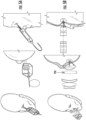
- FIGS. 1A-1C present a selection of inner eye lid images obtained using Spectral Domain Ophthalmic Imaging System provided by Bioptigen, Envisu TM R2300 Spectral Domain Ophthalmic Imaging System.
- the images in FIGS. 1A-1C illuminate the capabilities of SDOCT in imaging inner eye lid fine structure.
- FIG. 1A illustrates a series of B-scan on the left, which follow the path of a Meibomian duct (circled) from the surface of the marginal conductiva to the deeper layers.
- FIG. 1A is a volume intensity projection through the entire stack of B-scans in a 5 mm ⁇ 5 mm volumetric image if the marginal conjunctiva area.
- FIG. 1B the electron micrographs on the right illustrate the distribution of Meibomian glands around the ducts in the tarsal and marginal portion of the conjunctiva.
- the B-scans on the left appear to illustrate the ducts and surrounding glands in the tarsal conjunctiva of a normal volunteer.
- the B-Scan on the top also shows what appears to be a global cell.
- FIG. 1C illustrates an anatomical drawing of an eyelid showing Meibomian glad on the left.
- FIG. 1C illustrates a cross-section of the eyelid to sclera illustrating tear film and two goblets.
- Bioptigen Envisu TM R4300
- the Bioptigen system has a 7.5 mm depth of view and may be suitable for direct full range imaging of anterior chamber.
- this system provides full range anterior segment SDOCT with 7.5 mm depth of view, a 4.0 ⁇ m resolution acquired at 20 frames per second.
- FIGS. 3A-I illustrate a corneoscleral junction with contact lens; keratoconus; riboflavin over partially epithelium stripped cornea after cross-linking; corneal opacity; opacity post treatment with PTK; FS LASIK flap; Microtome LASIK flap; DSAEK with trapped bubble; DSAEK bubble eliminated, respectively.
- the subject in the image of FIGS. 3A through 3I is wearing a contact lens; the difficulty of oblique imaging is apparent when one tries to resolve the contact lens fit at the limbus.
- Another problem is that visualization of the angle is hampered, as the scanned ray travels a greater distance through the sclera to reach the angle than would be necessary on normally directed viewing. Accordingly, improved systems are desired.
- Some embodiments of the present inventive concept provide scanning optical beam imaging systems for imaging a surface with convex curvature.
- the systems include a sphero-telecentric objective, wherein a scanning radius of curvature of the sphero-telecentric objective is greater than an apical radius of curvature of the surface and less than or equal to four times an apical radius of curvature of the surface.
- the sphero-telecentric objective may include lens elements arranged in four or fewer lens groups.
- the sphero-telecentric objective includes an aspheric optical element.
- the scanning optical beam imaging system may be an optical coherence tomography imaging system.
- the scanning optical beam imaging system may be an input beam zoom.
- the input beam zoom may include an input light source; a positive lens group in a first position; a movable negative lens group in a second position; a movable positive lens group in a third position, wherein relative positions of the movable negative lens group in the second position to the positive lens group in the first position, and the moveable positive lens group in the third position to the movable negative lens group in the second position control a numerical aperture and a degree of focus of the imaging system.
- the scanning optical beam imaging system may include a telecentric scanning input.
- the telecentric scanning input may include an input light source; an input beam shaping system; a first mirror set to scan along a first direction; a first telecentric relay configured to image the first mirror set to a second mirror set to scan along a second direction orthogonal to the first direction; and an objective that receives the telecentrically scanned input beam to a region of a subject
- Some embodiments of the present inventive concept provide ophthalmic optical coherence tomography imaging systems including a sphero-telecentric imaging objective, wherein a scanning radius of curvature of the sphero-telecentric objective is greater than an apical radius of curvature of a cornea of the eye and less than or equal to four times an apical radius of curvature of the cornea of the eye.
- the sphero-telecentric objective may include lens elements arranged in four or fewer lens groups.
- the sphero-telecentric objective includes an aspheric optical element.
- the optical coherence tomography imaging system may further include an input beam zoom.
- the input beam zoom may include an input light source; a positive lens group in a first position; a movable negative lens group in a second position; a movable positive lens group in a third position, wherein relative positions of the movable negative lens group in the second position to the positive lens group in the first position, and the movable positive lens group in the third position to the negative lens group in the second position controls a numerical aperture and a degree of focus of the imaging system.
- the optical coherence tomography imaging system may include a telecentric scanning input.
- the telecentric scanning input may include an input light source; an input beam shaping system; a first mirror set to scan along a first direction; a first telecentric relay that images the first mirror set to a second mirror set to scan along a second direction orthogonal to the first direction; and an objective that receives the telecentrically scanned input beam to a region of a subject.
- sample being an eye, specifically, the retina, cornea, anterior segment and lens of the eye
- embodiments of the present inventive concept are not limited to this type of sample. Any type of sample that may be used in conjunction with embodiments discussed herein may be used without departing from the scope of the present inventive concept.
- Some embodiments of the present inventive concept provide an imaging system that is more suited to clinically useful imaging of the cornea, the tear film, and the tissue ultrastructure of the inner eyelid, conjunctiva and sclera.
- Optics suited for imaging curved surfaces with a wide field of view are provided.
- the following challenges have been address: (1) Invert the scanned focal field to match the surface of the cornea; (2) Equalize the optical path lengths so that a spherical surface is imaged to a plane at constant image depth; and (3) Introduce optical elements that allow such a design to be compact and cost effective.
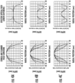
- the solid lines (left) are cornea shape, i.e. the shape that will be imaged by traditional telecentric OCT optics.
- the dashed lines (left) represent the focal field of the target optics.
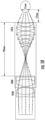
- FIGS. 4A-4C illustrate Aspheric OCT Scan Field Curvature vs. Cornea Shape. Telecentric imaging of cornea surface requires deep imaging for wide field of view (solid lines, left). Sphero-telecentric imaging reduces the required depth of view, and provides a surface image as a deviation from spherical (right).
- FIG. 4A illustrates a spherical cornea model, radius of curvature 7.5 mm;
- FIG. 4B illustrates a Spherical model with exponential tails;
- FIG. 4C illustrates a keratonic model. The lines indicated the scanner field radius: 6 mm (----); 7.5 mm (--..--); 9 mm (--....--), respectively.
- focal field In traditional OCT the focal field will typically be flat or slightly curved upwards. There are at least two ways to achieve a focal field more adequately matched to outwardly curved surfaces with important ramifications.
- aspheric optics are used to focus further along the z axis as a function of distance from the optical axis.
- the rays remain nominally telecentric.
- telecentric refers to chief rays that remain substantially parallel to the originating optical axis.
- the resolution and image brightness at the target surface are substantially equalized, but the path lengths are not; the shape of the cornea may appear as with traditional OCT, but resolution and brightness across the field of view (FOV) will be improved.
- the scanning rays are directed normal to a target field surface, specifically to a spherical field surface.
- "normal” refers to being perpendicular to the surface of the target sphere. In these embodiments, the beams would be normal to a target sphere and, therefore, there would be no refractive warping on passing through the target surface.
- the path lengths away from the optical axis could be severely elongated and the surface distortion unmanageable.
- the path lengths are equal across the field.
- a spherical subject contour would appear as a flat surface at constant depth.
- FIGS. 4A-4C the surfaced contours as imaged by a Sphero-Telecentric OCT system as graphed on the right for three model cornea shapes.
- a spherical cornea ( FIG. 4A ) with radius of curvature larger than the scanner field curvature would appear to curve upward.
- a cornea with radius of curvature smaller than the scanner field curvature would appear to curve downward.
- the shape illustrated in FIG. 4B is a slightly more realistic model of a healthy cornea and the FIG. 4C illustrates a keratoconic model.
- the imaged shape of the cornea will be a direct map of the deviation from sphericity; imaged in three dimensions, this surface contour will lend itself to immediate decomposition into Zernike components. Furthermore, even for significant deviation from spherical, the entire surface of a cornea will map into a field depth half that of the telecentrically imaged subject, providing significant depth of field for tissue imaging and evaluation using a system, such as the Envisu R4300.
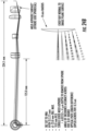
- FIGS. 5A-5B two designs using aspheric optics are illustrated.
- FIG. 5A illustrates a design using Focal Inversion
- FIG. 5B illustrates a design using Sphero-Telecentricity.
- the associated performance parameters the aspheric head designs for FIGS. 5A and 5B are listed in Table 1 set out below.
- Table 1 Concept Spot Size (um) OPL Variation (mm) Working Distance (mm) Device Length (cm) Airy RMS vs FOV (mm) 0 3 5 7 9
- design 1 offers exceptional resolution across the surface of a cornea (5-15 ⁇ m) in an 18 mm field of view, and a compact package (10 cm in length).
- the path length variation across the field is 4.3 mm. This neither collapses a spherical target to a plane, nor is path length directly correlated to a useful function; the shape of the image cornea could be derived from calibration of the scanned field, but this introduces an additional complexity.
- design 2 achieves the objective of path length equalized Sphero-Telecentricity.
- the path length variation across a 14 mm field of view is 5 ⁇ m (0.005 mm), which is exceptional.
- This is accomplished by an inventive use of aspheric imaging optics together with a novel shaped path equalizing element (PEQ).
- PEQ novel shaped path equalizing element
- the resolution remains within 15 ⁇ m across the field.
- the trade-off is an increase in optical elements and device length, at 25 cm.
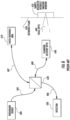
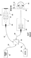
- the system includes a broadband source 600, a reference arm 610 and a sample arm 640 coupled to each other by a beamsplitter 620.
- the beamsplitter 620 may be, for example, a fiber optic coupler or a bulk or micro-optic coupler without departing from the scope of the present invention.
- the beamsplitter 620 may provide from about a 50/50 to about a 90/10 split ratio.
- the beamsplitter 620 is also coupled to a wavelength or frequency sampled detection module 630 over a detection path 606 that may be provided by an optical fiber.
- the source 600 is coupled to the beamsplitter 620 by a source path 605.
- the source 600 may be, for example, a SLED or tunable source.
- the reference arm 610 is coupled to the beamsplitter over a reference arm path 607.
- the sample arm 640 is coupled to the beamsplitter 620 over the sample arm path 608.
- the source path 605, the reference arm path 607 and the sample arm path 608 may all be provided by optical fiber.
- the sample arm 640 may include scanning delivery optics and focal optics 660. Also illustrated in FIG. 6 is the reference plane 650 and a representation of an OCT imaging window 670.
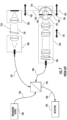
- the reference arm 710 may further include a collimator assembly 780, a variable attenuator 781 that can be neutral density or variable aperture, a mirror assembly 782, a reference arm variable path length adjustment 783 and a path length matching position 750, i.e. optical path length reference to sample.
- the sample arm 740 may include a dual-axis scanner assembly 790 and a variable focus objective lens 791.
- the sample in FIG. 7 is an eye including a cornea 795, iris/pupil 794, ocular lens 793 and retina 796.
- a representation of an OCT imaging window 770 is illustrated near the retina 796.
- the retinal imaging system relies in the optics of the subject eye, notably cornea 795 and ocular lens 7, to image the posterior structures of the eye.
- FIG. 8 a block diagram illustrating a FDOCT cornea imaging system will be discussed. As illustrated therein, the system of FIG. 8 is very similar to the system of FIG. 7 . However, the objective lens variable focus need not be included, and is not included in FIG. 8 .
- the anterior imaging system of FIG. 8 images the anterior structures directly, without reliance on the optics of the subject to focus on the anterior structures.
- the system 900 includes a fiber input 901, a scanning mirror 911, a telecentric scanning lens 921, telecentric scanning beams 931 that culminate at the sample, for example, and eye 941.
- the lens group includes an objective lens set 1050/1060 and a curved lens group 1076.
- the curved lens set 1076 may provide embodiments where the rays are more perpendicular to the surface of a curved sample. This may provide a stronger signal for layered structures, such as the cornea.
- the system of FIG. 10 may essentially flatten the structure being imaged and, therefore, provide more detailed images within the readily achievable depth range of FDOCT systems.
- the human eye does not have a uniform curvature.
- the diameters of portions of the eye may vary from about 8.0 mm (for the cornea) to about 12.0 mm (for the rest of the globe).
- the curved lens set 1076 illustrated in FIG. 10 may provide a lens designed to form a flat image of a curved object, for example, the human eye.
- the rays are normal to the curved surface to allow a zero optical path difference across the entire field of view.
- the curved lens set 1076 is configured to adapt to an existing retinal imager or OCT scanner to achieve cornea and OCT imaging in a flat plane.
- the curved lens set 1076 or multi-element lens may be configured to image a curved object, such as the surface of the cornea, onto a flat plane, such as the intermediate focus plane between the scanning and objective lenses.
- FIG. 11 a block diagram illustrating sphero-telecentric imaging in accordance with some embodiments of the present inventive concept will be discussed.
- imaging Geometry for sphero-telecentric imaging in accordance with some embodiment discussed herein has a radius of curvature (a), which is a target radius of curvature for imaging; an objective diameter of the lens (b) which provides a clear aperture of imaging objective; a working distance (c), which is the distance from imaging objective to surface of subject, for example, the apex of the cornea; a field of view (FOV) (s), which is angular extent or chord of the spherical surface to be imaged; and a region of constant optical path length distance (OPLD) (e), which is a sub region of the field of view over which optical path length uniformity is maintained.
- a radius of curvature
- b objective diameter of the lens
- c the working distance from imaging objective to surface of subject, for example, the apex of the cornea
- FOV field of view
- OPLD region of constant optical path length distance
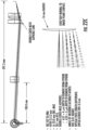
- FIG. 12 a telecentric scanning system with focus control, numerical aperture (NA) control and beam expansion in accordance with some embodiments of the present inventive concept will be discussed.
- This system may provide for a highly telecentric surgical system, for example. As illustrated in FIG. 12
- the telecentric imaging system includes a fiber input (a), which may include a single mode fiber; a collimator (b); an input beam zoom (input beam shape control), which provides the ability to adjust focus and control Numerical Aperture (NA); mirror axis 1 (d); a telecentric relay half 1 (e), which is a telecentric modified-Wild-eye-piece design; a telecentric relay half 2 (f), which is similar to (e); a mirror axis 2, orthogonal to mirror axis 1 (g); a telecentric relay half 3 (h), which is similar to (e); a telecentric beam expander (i); an imaging lens (j), which may be achromatic doublet; and a subject, which many be an eye.
- a fiber input which may include a single mode fiber
- a collimator b
- an input beam zoom input beam shape control
- NA Numerical Aperture
- mirror axis 1 (d) a telecentric relay half 1 (e), which
- FIGS. 13A through 13C illustrate a series of diagrams illustrating an input beam zoom (IBZ) for input beam shape control.
- FIG. 13A illustrates a method of shaping the interrogating beam.
- the collimating lens that follows the input optical fiber is allowed to move away from collimation, indicated by the arrow a to b.
- This design is discussed in U.S. Pat. No. 7,843,572 to Tearney for an endoscopic delivery system.
- the movement of the collimating lens impacts both focus and numerical aperture of the beam delivery without enough degrees of freedom to shape the beam in a sufficiently controlled manner.
- FIG. 13B a second moveable negative lens is added after the first movable positive lens.
- the arrangement illustrated in FIGS. 13B improves the separation of focus and numerical aperture. However, allowing movement of the initial collimating lens in this set up adversely impacts aberrations in the downstream system and may modulate the radiant power in the system, particularly if a small aperture truncates the beam originating in the source or source fiber.
- a fixed collimated beam is used followed by a moveable positive lens.
- a moveable positive lens is used in this embodiment, only the position of the focus can be changed, there is no effect on the NA.
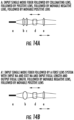
- FIGS. 14A and 14B are a series of diagrams illustrating input beam shape control in accordance with some embodiments of the present inventive concept. Some embodiments of the present inventive concept provide a focal system that addresses the issues discussed above with respect to FIGS. 13A through 13C in providing constant radiant power to the downstream system, and sufficient degrees of freedom to independently control numerical aperture (NA) and focus.
- NA numerical aperture
- an input source or source fiber is followed by a first positive lens (b) positioned nominally one focal length away from the source, thus collimating the source.
- the first positive lens (b) is followed by a second positive lens (c) that provides a first focal power to the system.
- the second positive lens (c) is followed by a third lens (d) that is a movable negative lens that modifies the power of the second positive lens (c).
- the negative lens (d) is followed by a fourth lens (e), which is a movable positive lens that controls the final output of this multi-lens system.
- FIG. 14B the single mode fiber (a) is followed by a first lens system (b) having an input NA and an exit NA and input focal length and output focal length.
- the first lens system (b) is followed by movable negative lens system (d), which followed by movable positive lens system (e).
- the output of the input beam zoom is a collimated beam that is focused by downstream optical elements.
- the numerical aperture of the complete system may be modified without modifying the degree of collimation or focus.
- a modified focal state may be achieved by independent movement of the final lens, the focus is modified.
- the method of setting numerical aperture and focus need not follow the sequential adjustment discussed above.
- a lookup table may be used to select the positions of the lens systems to achieve a desired combined output state.
- the lens system (b) of FIG. 14B may be substantially equivalent to the first and second positive lenses (b and c) of FIG. 14A , and conversely that lens systems (d) and (e) may not be lens singlets but may be more complex lenses or groups of lenses.
- FIGS. 15A through 15C a series of block diagrams illustrating diagrams of lens positions for beam shape control for high numerical aperture, low numerical aperture and low numerical aperture with deep focus, respectively, in accordance with some embodiments of the present inventive concept will be discussed.
- Lens (a) is the first positive lens
- lens (b) is the second negative lens
- lens (c) is the third positive lens.
- the distance between lens (a) and lens (b) will be referred to as the first lens spacing (D1) and the distance between lens (c) and lens (b) will be referred to as the second lens spacing (D2).
- the position of the lens (a) is fixed in all of FIGS. 15A through 15C .
- lens (b) and lens (c) are both moveable in all of FIGS. 15A through 15C .
- FIG. 15A illustrates embodiments for a high numerical aperture imaging system.
- the zoom controls the numerical aperture of the system; in a collimated application, where the final focus is determined by downstream optics, the zoom magnification provides a magnification between the entrance pupil and exit pupil. The larger this magnification, the greater the numerical aperture of the final imaging system.
- FIG. 15B illustrates embodiments having a low numerical aperture, the first spacing D1 has increased and the second spacing D2 has decreased.
- FIG. 15C illustrates embodiments having a low numerical aperture and deeper focus, the second spacing D2 has further decreased and the system has been modified from a collimated state to a diverging state.
- the zoom factor refers to the zoom factor as a function of first and second lens spacing, D1 and D2 discussed with respect to FIG. 15A through 15C .
- the first lens spacing (D1) is the distance to the negative lens from the first positive lens and the second lens spacing (D2) is the distance to the final positive lens from the negative lens.
- FIG. 17 a graph illustrating IBZ focal power as a function of final lens spacing in accordance with some embodiments of the present inventive concept will be discussed.
- focus may be adjusted by movement of the final lens of the IBZ (lens c of FIGS. 15A through 15C ).
- Increasing the second lens spacing (D2) increases the focal power of the IBZ, and shortens the focal length of the system. Reducing the second lens spacing (D2) reduces the focal power of the IBZ and increases the focal length of the system.
- lens spacing D1 and lens spacing D2 provide a continuous range of control of system numerical aperture and focus.
- the range of control is dependent on the available physical space for movement of the lenses, the respective powers of the lenses, and the downstream imaging optics, as will be understood by one skilled in the art. It will also be noted that the imaging conditions are deterministic, and multiple modes of control may be employed to achieve a desired state, including without limitation, sequential or simultaneous movement of lens, movement according to values set in a lookup table, or adjustment with feedback based on positional encoders or in response to image quality feedback.
- the system includes a two telecentric GRLs (modified Wild eyepiece), i.e. a first GRL half (GRLH) and a second GRLH.
- GRLH modified Wild eyepiece
- Each GRLH includes a first positive doublet (a) that is fixed, a positive singlet pair (b) that is fixed and a second positive doublet (c) that is fixed.
- the GRLs control the telecentricity of the system.
- the GRL as proposed enables a very high degree of telecentricity along two orthogonal axis. This telecentricity has not been deployed previously in scanning beam ophthalmic imaging systems.
- FIG. 19 a block diagram illustrating an optical path length and telecentricity manager in accordance with some embodiments of the present inventive concept will be discussed.
- an optical path management objective sinhero-telecentric objective (OPMO) is introduced in the system after the final GRL.
- OPMO optical path management objective
- the system includes a fiber input (a); a collimator (b); an input beam zoom (c); a mirror axis 1 scanning a long a first axis (d); a telecentric relay half 1 (e); a telecentric relay half 2 (f); a mirror axis 2 scanning along a second axis orthogonal to the first (g); a telecentric relay half 3 (h); an optical path managed objective (OPMP) (i); and a subject (j).
- a fiber input a
- a collimator b
- an input beam zoom a mirror axis 1 scanning a long a first axis (d); a telecentric relay half 1 (e); a telecentric relay half 2 (f); a mirror axis 2 scanning along a second axis orthogonal to the first (g); a telecentric relay half 3 (h); an optical path managed objective (OPMP) (i); and a subject (j).
- OPMP optical path managed objective
- a sphero-telecentric imaging objective will focus normal to a spherical surface with a target radius of curvature.
- a Path-Managed sphero-telecentric objective for OCT imaging may ensure that the optical path length will be constant across the field of view (FOV) along the target radius of curvature.
- the cornea of a human eye is not perfectly spherical.
- the normal eye has a nominal radius of curvature of about 8 mm at the apex, increasing towards the limbus.
- an imaging system is provided have a 16 mm radius of curvature, or 2 times the nominal apical radius of curvature.
- a radius of curvature larger than the apical radius of curvature of the cornea is chosen to allow a large field of view (FOV) with a comfortable working distance and an objective diameter that does not interfere with the subject physiology, for example, the brow or the nose of the subject.
- FOV field of view
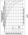
- the cosine of the angle of incidence of the interrogating beam onto the cornea is plotted as a function of the position along the half field of view, normalized to the cornea radius, for different values of the ratio of the imaging radius of curvature to the cornea radius of curvature.
- the imaging radius of curvature may be equal to or greater than the apical cornea radius.
- the imaging radius of curvature may be between about 1 ⁇ and about 4 ⁇ the apical radius of curvature of the cornea, or between about 1.5 ⁇ and about 3 ⁇ the apical radius of curvature of the cornea in order to optimize the trade-offs discussed.
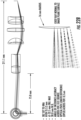
- the sphero-telecentric system includes a fiber input (a); a collimator (b); an input beam zoom (c); a mirror axis 1 (d); a telecentric relay half 1 (e); telecentric relay half 2 (f); a mirror axis 2 (g); a 16 mm sphero-telecentric objective (h); and a subject (i).
- the sphero-telecentric imaging system may include a collimated (a) source followed by an input beam zoom (IBZ) (b).
- the beam images on a first galvo mirror (d) will scan in one direction.
- the first galvo (e) is telecentrically imaged onto a second galvo (f) that will scan in a second orthogonal direction.
- the input source is then imaged on the subject using the path-managed sphero-telecentric objective (h).
- the objective (h) includes four groups of optics in embodiments illustrated in FIG. 22B .
- the sphero-telecentric objective imaging to a 16 mm radius of curvature over a 6.4 mm field of view is prescribed using spherical (normal glass) optics.
- the four groups include a first doublet followed by a pair of singlets and a final doublet.
- the working distance (final lens to cornea) is 30 mm.
- the maximum diameter of the objective is 32.5 mm.
- the system images to an angle accuracy of 0.01 degree, with an optical path length consistent to 0.3 ⁇ m, thus exhibiting a very high degree of sphero-telecentricity as referenced to the 16 mm target surface.
- the objective (h) includes three groups of optics in embodiments illustrated in FIG. 22C .
- a sphero-telecentric objective imaging to a 16 mm radius of curvature over a 6.4 mm field of view is prescribed using a combination of spherical (normal glass) and aspheric optics including elements in three groups.
- the groups include a first doublet followed by a double-sided asphere and a final doublet,
- the aspheric surfaces are mild aspheres, requiring less than 5 ⁇ m depth to remove from the sphere, a prescription for defining and asphere as is known in the art.
- the working distance (final lens to cornea) is 30 mm,
- the maximum diameter of the objective is 33 mm.
- the system images to an angle accuracy of 0.01 degree, with an optical path length consistent to 0.3 ⁇ m, thus exhibiting a very high degree of sphero-telecentricity as referenced to the 16 mm target surface, using fewer lens elements than the spherical optic design of FIG. 22B .
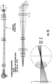
- the 12 mm sphero-telecentric system using spherical optics includes 6 lens groups.
- the sphero-telecentric objective imaging to a 12 mm radius of curvature over a 5.5 mm field of view is prescribed using spherical (normal glass) optics comprising elements in six groups.
- the groups include a first pair of doublets followed by a third doublet, a fourth doublet, a singlet and a final doublet.
- the working distance (final lens to cornea) is about 14 mm.
- the maximum diameter of the objective is about 22.6 mm.
- the system images to an angle accuracy of 0.01 degree, with an optical path length consistent to 0.3 um.
- a 12 mm sphero-telecentric system using aspheric optics includes 4 lens groups, reduced from 6 in the embodiment discussed with respect to FIG. 23A .
- a sphero-telecentric objective imaging to a 12 mm radius of curvature over a 5.5 mm field of view is prescribed using spherical (normal glass) and aspheric optics includes elements in four groups.
- the four groups include a first singlet, a first doublet, a first single-sided asphere, and a final doublet.
- the aspheric surface is a mild asphere, which may require less than 4.0 mm depth to remove from the sphere.
- the working distance (final lens to cornea) is about 14.2 mm.
- the maximum diameter of the objective is about 27 mm.
- the system images to an angle accuracy of 0.01 degree, with an optical path length consistent to 0.3 um.
- FIGS. 24A and 24B diagrams illustrating a sphero-telecentric system having a 8 mm radius of curvature in accordance with some embodiments of the present inventive concept will be discussed.
- the 8 mm sphero-telecentric system using spherical optics includes a complicated series of optics.
- a sphero-telecentric objective imaging to an 8 mm radius of curvature over a 4.5 mm field of view is prescribed using spherical (normal glass) optics including elements in multiple groups as illustrated in FIG. 24A .
- the working distance (final lens to cornea) is about 10 mm.
- the maximum diameter of the objective is about 19 mm.
- the system images to an angle accuracy of 0.01 degree, with an optical path length consistent to 0.3 ⁇ m.
- the complex design illustrated in FIG. 24A is provided to illustrate the variety of designs that may be brought to bear on the problem.
- the 8 mm sphero-telecentric system using aspheric optics reduces the complicated set of optics illustrated in FIG. 24A to optical elements arranged in 4 groups.
- a sphero-telecentric objective imaging to an 8 mm radius of curvature over a 5.5 mm field of view is prescribed using spherical (normal glass) and aspheric optics comprising elements in four groups.
- the four groups include a first doublet, a first singlet, a first single-sided asphere, and a final doublet.
- the aspheric surface is a mild asphere, requiring less than about 4 ⁇ m depth to remove from the sphere.
- the working distance (final lens to cornea) is about 10 mm.
- the maximum diameter of the objective is about 23 mm.
- the system images to an angle accuracy of 0.01 degree, with an optical path length consistent to 0.4 m.
- the degree of path length constancy in this design is better than 0.005% over the 5.5 mm field of
- FIG. 25 a sphero-telecentric system having a 12 mm radius of curvature defocused to image to the retina in accordance with some embodiments of the present inventive concept will be discussed. It will be understood that although embodiments of FIG. 25 are discussed with respect to a 12 mm sphere-telecentric system, embodiments of the present inventive concept are not limited to this configuration. For example, 8 mm and 16 mm sphero-telecentric are examples of other system designs that can be defocused using the same techniques discussed below with respect to FIG. 25 without departing from the scope of the present inventive concept.
- a sphero-telecentric system can be defocused using, for example, an IBZ or paraxial lens inserted after the second galvo (EFL 263 mm ⁇ 3.8 D).
- IBZ Input Beam Zoom
- the retina is imaged across a 40 degree field of view (FOV) by counter-intuitively shifting Lens (c) of the IBZ forward 6.5 mm relative to the position for cornea imaging.
- This adds power to the IBZ, and shifts the focus backwards to an intermediate position within the sphero-telecentric objective.
- an internal conjugate forms, and this internal conjugate is then imaged forward to the retina.
- the reference arm path length is adjusted to shift the interferometric condition from the front of the eye to the back. In this mode of operation, the transition between an anterior imaging telecentric system to a posterior imaging scan pivoting system is accomplished without the addition or subtraction of any lens element.
- embodiments are not limited to using the IBZ.
- the same or similar effect may be achieved by adding a paraxial lens to the system, for example, after the second galvo.
- a 3.8 D lens may be used.
- the sphero-telecentric design may enable multiple application modes.
- the IBZ focus control may be used to scan across an entire depth of an eye from cornea through retina with a continuous motion of the IBZ front lens (lens c).
- the front lens of the IBZ is moved forward sufficiently to move a beam conjugate into an interstitial space within the sphero-telecentric objective.
- This conjugate is then imaged forward of the sphero-telecentric lens to a structure of the eye.
- the front lens of the IBZ is positioned increasingly forward, increasing the optical power of the IBZ, the internal, or interstitial, conjugate moves increasingly backwards, and the image of this conjugate is pulled increasingly forward with respect to the subject structure, as illustrated in FIG. 26A .
- the conjugate is imaged at the cornea.
- the conjugate is imaged at the retina.
- the function is continuous.
- a coordinated control of the reference arm of the OCT engine with the focus of the IBZ allows acquisition of OCT data continuously along the length of the eye or other translucent object.
- the working distance is increased such that the subject is at a working distance greater than the sphero-telecentric radius of curvature.
- the working distance for the eye becomes 37.5 mm. Note that this implies that the imaging is beyond the crossing point of the convergent beams; this system thus works primarily on-axis with a limited field of view (FOV) but is quite suitable for axial length assessment.
- FOV field of view
- a second mode the mode described for anterior segment imaging, and extension to posterior segment imaging is enabled.
- the working distance is constant as described for the sphero-telecentric imaging.
- the IBZ zoom power is reduced by pulling the front lens position back, closer to the negative lens of the IBZ, the focusing power of the system is reduced on interior surfaces of the anterior segment, such as the anterior surface of the crystalline lens may be imaged. This defocusing is insufficient to image through to the retina.
- the IBZ zoom power is increased, contrary to intuition as discussed above. This is because the conjugate is pulled to the interstitial space of the objective, as discussed above, and then imaged back to the retain. Posterior regions may be imaged so long as they are posterior to the crossing of the scanning rays, by appropriate control of the reference arm and IBZ zoom, as illustrated in FIG. 26B .
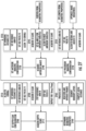
- FIG. 27 a flowchart illustrating operations for an imaging ocular biometer using sphero-telecentric optics in accordance with some embodiments of the present inventive concept will be discussed.
- the dual mode capability of the sphero-telecentric imaging system enables a unique and novel imaging biometer well suited to ocular diagnostics.
- axial biometry is measured with the system in depth scan mode (Mode 1 of FIG. 26A ), and the measurements derived from the axial biometry are used to image both anterior and posterior structures of the eye in the second, imaging mode.
- Operations begin at block 2700 by setting a depth scan configuration.
- the system is aligned to the cornea; the working distance D1 (here D1 refers to working distance, not to the IBZ lens spacing D1 as used previously) is set to the depth scanning configuration, for example, 37.5 mm; the reference arm is set to the appropriate position for imaging the cornea; and the IBZ focus is set to the collimated position (blocks 2710).
- a series of scans are acquired throughout the depth (block 2715).
- a limited range B-scan for example, 2 mm, is acquired at least one time, and if multiple times they may be averaged for improved signal-to-noise; the reference arm path length is increased by a fraction of the eye length; the IBZ focus power is increased according to the relationship as illustrated in FIG. 26B (blocks 2720).
- blocks 2720 may be repeated, for example, a second B-scan is acquired; the reference arm step is selected to be a fraction of the individual OCT A-scan length, for example 1/10ththe distance of the FDOCT scan window, so that subsequent scans may be aligned; and this process is repeated until the entire eye length is mapped (blocks 2715, 2720).
- a sequence of about 100 B-scans stepped at 250 ⁇ m, each comprising about 100 A-scans acquired at 32,000 A-scans per second will be map the axial length of the eye in approximately 1/3 of a second. With 3 ⁇ averaging, the time increases to only about 1 second. At 70,000 A-scans per second, the acquisition time is back below half a second. This timing is also reasonable for stepping the IBZ lens and the reference arm using electromechanical actuators known in the arts.
- the data is processed to identify structures in each B-scan that represent the structures in the eye, using layer segmentation algorithms, or using new algorithms designed for the purpose (blocks 2760 and 2765).
- layer segmentation algorithms or using new algorithms designed for the purpose.
- a linear data set identifying structural boundaries as a function of axial position is derived, and these positions may be used during the imaging phase to set the system parameters for both anterior and posterior imaging.
- FIG. 28 a diagram illustrating an axial biometer acquisition in accordance with some embodiments of the present inventive concept will be discussed.
- the B-scans having a width W are stacked for the entire eye length EL as a function of depth in the eye for the depth scanning mode to be used in ocular biometry.
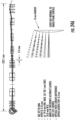
- FIG. 29 a flow diagram illustrating imaging both the anterior and posterior segments of the eye in accordance with some embodiments of the present inventive concept will be discussed.
- Some embodiments of the present inventive concept provide a third mode of operation for sphero-telecentric imaging system with input beam zoom (IBZ).
- the third mode of operation allows combined axial biometry and anterior and posterior imaging, through continuous exploration of the structures of an eye from cornea through retina using a coordinated change of position of the two movable lenses in the IBZ to shift the focus, together with a shift in the reference arm to coincide the OCT interferometric imaging condition with the focus.
- the working distance is maintained at a fixed imaging distance. In 12 mm imaging radius embodiments, the working distance is about 14 mm.
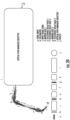
- the system includes a fiber input (a); a collimator (b); an input beam zoom (IBZ) (c); a mirror axis 1 (d); a telecentric relay half 1 (e); a telecentric relay half 2 (f); a mirror axis 2 (g); an optical path managed objective (OPMO) (h); and a subject (i).
- part (c) the input beam zoom (IBZ) is blown up and includes three lenses, a, b and c.
- the OPMO or sphero-telecentric objective includes first through fourth lens groups, I, II, III and IV.
- the settings for lenses a, b and c of the IBZ (c) and the STO (i) are provided in the various charts of FIGS. 30A-C for modes 1 (imaging mode) and mode 3 (combined imaging/biometry mode) discussed above.
- FIGS. 30A-30C are applicable to mode 2 without departing from the scope of the present inventive concept
- FIG. 31 a flow chart illustrating operations for an Imaging Ocular Biometer using sphero-telecentric optics in accordance with some embodiments of the present inventive concept will be discussed.
- the multi-mode capability of the sphero-telecentric imaging system enables a unique and novel imaging biometer well suited to ocular diagnostics.
- Operations begin at block 3100 by setting an imaging scan configuration.
- the system is aligned to the cornea; the working distance D1 is set to the imaging scanning configuration, for example, 14 mm; the reference arm is set to the appropriate position for imaging the cornea; and the IBZ lens positions are set to is set to the cornea imaging positions as prescribed in the table for Mode 3 of FIG. 30 (blocks 3105).
- Operations proceed to blocks 3107 and 3110 where a series of scans are acquired throughout the depth.
- B-scans are acquired over the field of view applicable to the imaging position, per the Table. Scans may be acquired one time, or multiple times for averaging; the reference arm path length is increased by a fraction of the eye length; and the IBZ lens settings are modified according to the Table. Until the entire eye is mapped.
- the data is then processed to identify structures in each B-scan that represent the structures in the eye, using layer segmentation algorithms, or using new algorithms designed for the purpose (blocks 3120 and 3125).
- layer segmentation algorithms or using new algorithms designed for the purpose (blocks 3120 and 3125).
- a linear data set identifying structural boundaries as a function of axial position are derived, and these positions may be used is establish biometric properties of the eye, including an axial eye length, and lengths to or thicknesses of major structures of the eye including cornea thickness, anterior segment depth, crystalline lens thickness, posterior chamber depth, retinal thickness, etc. (blocks 3130 and 3135). Additionally, pathologies may be identified as a function of position within the eye, measured, and unambiguously referenced to structures of the eye. Oct angiographic techniques, including Doppler OCT and other methods of extracting vascular information known in the art may be applied to discern blood flow properties of the uveal and retinal circulatory systems of the eye.
- some embodiments of the present inventive concept provide a system design that can serve a unified purpose of imaging the ultrastructure of the inner eyelid, the meibomian ducts, the tearfilm meniscus and the cornea with a single compact handpiece.
- the system may used to image a spherical surface onto a plane with less than 100 ⁇ m deviation, with a resolution of better than 20 ⁇ m, across a 15 mm field of view. A flatness of better than 10 ⁇ m may be provided.
- the system may provide high quality, easily interpreted images of the inner eyelid, tear film, cornea and angle, which allow diagnostic assessment of structures relevant to dry eye disease and cornea dystrophies.
- Some embodiments of the present inventive concept provide a system design that can serve to improve the imaging of curved surfaces such as the cornea by increasing the degree of telecentricity to the curved surface, balanced to avoid excessive specular reflections arising from perfect telecentricity to reflective surfaces.
- Some embodiments of the present inventive concept provide a system design that can serve a unified purpose of combining ocular biometry with imaging of the anterior and posterior segments of the eye though one of multiple modes of measurement in the same optical system, without requiring the insertion or removal of a lens from the system to switch between imaging modes.
- Some embodiments of the present inventive concept provide for an input beam shaping mechanism that enables numerical aperture and focal control that may be extended to a range of optical beam imaging systems.
- Example embodiments are described above with reference to block diagrams and/or flowchart illustrations of systems and devices.
- the functions/acts noted in the blocks may occur out of the order noted in the flowcharts.
- two blocks shown in succession may in fact be executed substantially concurrently or the blocks may sometimes be executed in the reverse order, depending upon the functionality/acts involved.
- the functionality of a given block of the flowcharts and/or block diagrams may be separated into multiple blocks and/or the functionality of two or more blocks of the flowcharts and/or block diagrams may be at least partially integrated.
Landscapes
- Health & Medical Sciences (AREA)
- Life Sciences & Earth Sciences (AREA)
- Physics & Mathematics (AREA)
- Engineering & Computer Science (AREA)
- Surgery (AREA)
- Public Health (AREA)
- Biomedical Technology (AREA)
- Heart & Thoracic Surgery (AREA)
- Medical Informatics (AREA)
- Molecular Biology (AREA)
- Biophysics (AREA)
- Animal Behavior & Ethology (AREA)
- General Health & Medical Sciences (AREA)
- Veterinary Medicine (AREA)
- Ophthalmology & Optometry (AREA)
- Nuclear Medicine, Radiotherapy & Molecular Imaging (AREA)
- Radiology & Medical Imaging (AREA)
- General Physics & Mathematics (AREA)
- Optics & Photonics (AREA)
- Pathology (AREA)
- Signal Processing (AREA)
- Eye Examination Apparatus (AREA)
- Lenses (AREA)
Claims (15)
- Abtast-Bildgebungssystem mit optischem Strahl zum Abbilden einer Oberfläche mit konvexer Krümmung, wobei das System dadurch gekennzeichnet ist, dass es Folgendes umfasst:
ein sphäro-telezentrisches Objektiv einschließlich eines asphärischen optischen Elements und eines Weg-Ausgleichselements, wobei das Weg-Ausgleichselement (path equalizing element, PEQ) eine gewölbte Linsengruppe (1076) beinhaltet, wobei die gewölbte Linsengruppe konfiguriert ist, um die Oberfläche mit konvexer Krümmung auf einer flachen Ebene abzubilden, sodass die optische Weglängendifferenz über eine vorbestimmte Subregion des Sichtfelds in einem vorbestimmten Bereich ist. - System nach Anspruch 1, wobei das sphäro-telezentrische Objektiv angepasst ist, um Abtaststrahlen bereitzustellen, die senkrecht zur Oberfläche mit konvexer Krümmung sind, die abgebildet werden soll.
- System nach einem der vorhergehenden Ansprüche, wobei das sphäro-telezentrische Objektiv Linsenelemente umfasst, die in vier oder weniger Linsengruppen angeordnet sind.
- System nach einem der vorhergehenden Ansprüche, wobei das Abtast-Bildgebungssystem mit optischem Strahl ein Abbildungssystem für optische Kohärenztomographie ist.
- System nach einem der vorhergehenden Ansprüche, wobei das Abtast-Bildgebungssystem mit optischem Strahl einen Eingangsstrahl-Zoom umfasst.
- System nach Anspruch 4, wobei der Eingangsstrahl-Zoom Folgendes umfasst:eine Eingangslichtquelle;eine Sammellinsengruppe in einer ersten Position,eine bewegliche Zerstreuungslinsengruppe in einer zweiten Position,eine bewegliche Sammellinsengruppe in einer dritten Position, wobei relative Positionen der beweglichen Zerstreuungslinsengruppe in der zweiten Position zu der Sammellinsengruppe in der ersten Position, und die bewegliche Sammellinsengruppe in der dritten Position zur der beweglichen Zerstreuungslinsengruppe in der zweiten Position eine numerische Apertur und einen Grad des Fokus des Abbildungssystems steuern.
- System nach Anspruch 5 oder 6, wobei der Eingangsstrahl-Zoom angepasst ist, um einen Fokus des sphäro-telezentrischen Objektivs zu verschieben.
- Verwendung des Weg-Ausgleichselements des Systems nach einem der vorhergehenden Ansprüche, in dem ein Abtastkrümmungsradius des sphäro-telezentrischen Objektivs größer als ein apikaler Krümmungsradius der Oberfläche und kleiner als oder gleich wie viermal ein apikaler Krümmungsradius der Oberfläche ist.
- System nach einem aus Anspruch 1, konfiguriert als ein ophthalmisches Abbildungssystem für optische Kohärenztomographie
- System nach Anspruch 9, wobei das sphäro-telezentrische Abbildungsobjektiv angepasst ist, um Abtaststrahlen bereitzustellen, die senkrecht zur Oberfläche der Kornea des Auges sind, das abgebildet werden soll.
- System nach einem der Ansprüche 9 bis 10, wobei das sphäro-telezentrische Objektiv Linsenelemente umfasst, die in vier oder weniger Linsengruppen angeordnet sind.
- System nach einem der Ansprüche 9 bis 11, wobei das Abbildungssystem für optische Kohärenztomographie ferner einen Eingangsstrahl-Zoom umfasst.
- System nach Anspruch 12, wobei der Eingangsstrahl-Zoom Folgendes umfasst:eine Eingangslichtquelle;eine Sammellinsengruppe in einer ersten Position,eine bewegliche Zerstreuungslinsengruppe in einer zweiten Position,eine bewegliche Sammellinsengruppe in einer dritten Position, wobei relative Positionen der beweglichen Zerstreuungslinsengruppe in der zweiten Position zu der Sammellinsengruppe in der ersten Position, und die bewegliche Sammellinsengruppe in der dritten Position zur der Zerstreuungslinsengruppe in der zweiten Position eine numerische Apertur und einen Grad des Fokus des Abbildungssystems steuern.
- System nach Anspruch 12 oder 13, wobei der Eingangsstrahl-Zoom angepasst ist, um einen Fokus des sphäro-telezentrischen Objektivs von der Kornea des Auges zu der Retina des Auges zu verschieben.
- Verwendung nach Anspruch 8, unter Bezugnahme auf einen der Ansprüche 9 bis 14, in dem ein Abtastkrümmungsradius des sphäro-telezentrischen Objektivs größer als ein apikaler Krümmungsradius einer Kornea des Auges und kleiner als oder gleich wie viermal ein apikaler Krümmungsradius der Kornea des Auges ist.
Applications Claiming Priority (4)
| Application Number | Priority Date | Filing Date | Title |
|---|---|---|---|
| US201161566856P | 2011-12-05 | 2011-12-05 | |
| US201261620645P | 2012-04-05 | 2012-04-05 | |
| PCT/US2012/067951 WO2013085997A1 (en) | 2011-12-05 | 2012-12-05 | Optical imaging systems having input beam shape control and path length control |
| EP12809411.7A EP2790570B1 (de) | 2011-12-05 | 2012-12-05 | Optisches abbildungssystem mit eingangsstrahlformkontrolle und weglängenkontrolle |
Related Parent Applications (2)
| Application Number | Title | Priority Date | Filing Date |
|---|---|---|---|
| EP12809411.7A Division EP2790570B1 (de) | 2011-12-05 | 2012-12-05 | Optisches abbildungssystem mit eingangsstrahlformkontrolle und weglängenkontrolle |
| EP12809411.7A Division-Into EP2790570B1 (de) | 2011-12-05 | 2012-12-05 | Optisches abbildungssystem mit eingangsstrahlformkontrolle und weglängenkontrolle |
Publications (2)
| Publication Number | Publication Date |
|---|---|
| EP3597100A1 EP3597100A1 (de) | 2020-01-22 |
| EP3597100B1 true EP3597100B1 (de) | 2024-10-23 |
Family
ID=47472014
Family Applications (2)
| Application Number | Title | Priority Date | Filing Date |
|---|---|---|---|
| EP19186504.7A Active EP3597100B1 (de) | 2011-12-05 | 2012-12-05 | Systeme zur optischen bildgebung mit eingangsstrahlformsteuerung und weglängensteuerung |
| EP12809411.7A Active EP2790570B1 (de) | 2011-12-05 | 2012-12-05 | Optisches abbildungssystem mit eingangsstrahlformkontrolle und weglängenkontrolle |
Family Applications After (1)
| Application Number | Title | Priority Date | Filing Date |
|---|---|---|---|
| EP12809411.7A Active EP2790570B1 (de) | 2011-12-05 | 2012-12-05 | Optisches abbildungssystem mit eingangsstrahlformkontrolle und weglängenkontrolle |
Country Status (3)
| Country | Link |
|---|---|
| US (3) | US8864309B2 (de) |
| EP (2) | EP3597100B1 (de) |
| WO (1) | WO2013085997A1 (de) |
Families Citing this family (27)
| Publication number | Priority date | Publication date | Assignee | Title |
|---|---|---|---|---|
| CA2841373C (en) | 2011-07-28 | 2017-08-29 | Wavelight Gmbh | Device for assisting in the preparation of an operation on the human eye |
| EP3597100B1 (de) * | 2011-12-05 | 2024-10-23 | Leica Microsystems NC, Inc. | Systeme zur optischen bildgebung mit eingangsstrahlformsteuerung und weglängensteuerung |
| US20150021228A1 (en) | 2012-02-02 | 2015-01-22 | Visunex Medical Systems Co., Ltd. | Eye imaging apparatus and systems |
| US9655517B2 (en) | 2012-02-02 | 2017-05-23 | Visunex Medical Systems Co. Ltd. | Portable eye imaging apparatus |
| US9351639B2 (en) | 2012-03-17 | 2016-05-31 | Visunex Medical Systems Co. Ltd. | Eye imaging apparatus with a wide field of view and related methods |
| US8777412B2 (en) | 2012-04-05 | 2014-07-15 | Bioptigen, Inc. | Surgical microscopes using optical coherence tomography and related methods |
| EP3003123B1 (de) | 2013-06-04 | 2020-08-19 | Bioptigen, Inc. | Optisches kohärenztomografiebildgebungssystem und optisches laserabtastsystem mit einem strahlformenden optischen system mit einer +-+ linsendreiergruppe mit beweglicher zweiter und dritter linse, und verfahren |
| CN105934664B (zh) * | 2013-07-19 | 2021-02-26 | 纽约大学 | 使用显微纹理鉴别物理对象的计算机可访问介质、方法和系统 |
| CN105592829B (zh) | 2013-07-29 | 2018-11-16 | 拜尔普泰戈恩公司 | 用于外科手术的手术性光学相干断层成像术(oct)及其相关系统和方法 |
| WO2015031589A1 (en) * | 2013-08-28 | 2015-03-05 | Bioptigen, Inc. | Heads up displays for optical coherence tomography integrated surgical microscopes |
| US9913580B2 (en) | 2013-09-19 | 2018-03-13 | Canon Kabushiki Kaisha | Apparatus, method, and non-transitory medium for optical stabilization and digital image registration in scanning light ophthalmoscopy |
| EP3086706B1 (de) * | 2013-12-23 | 2021-03-24 | Alcon Inc. | Chirurgisches oct-visualisierungssystem mit breitem sichtfeld |
| US9986908B2 (en) | 2014-06-23 | 2018-06-05 | Visunex Medical Systems Co. Ltd. | Mechanical features of an eye imaging apparatus |
| US9724239B2 (en) | 2014-07-14 | 2017-08-08 | Novartis Ag | Movable wide-angle ophthalmic surgical system |
| WO2016041640A1 (de) * | 2014-09-19 | 2016-03-24 | Carl Zeiss Meditec Ag | System zur optischen kohärenztomographie, umfassend ein zoombares kepler-system |
| CN107708524A (zh) | 2015-01-26 | 2018-02-16 | 威盛纳斯医疗系统公司 | 用于眼睛成像装置的一次性隔离套以及相关方法 |
| CN106031629A (zh) * | 2015-03-10 | 2016-10-19 | 卡尔蔡司医疗技术公司 | 用于光学相干断层扫描仪的近视眼扫描模块 |
| US10588572B2 (en) * | 2017-05-08 | 2020-03-17 | Oregon Health & Science University | Bulk motion subtraction in optical coherence tomography angiography |
| WO2019010345A1 (en) * | 2017-07-07 | 2019-01-10 | University Of Rochester | OPTICAL DESIGN FOR TWO DEGREE FREQUENCY SCANNING SYSTEM WITH CURVED SAMPLE PLAN |
| US20190200854A1 (en) | 2018-01-03 | 2019-07-04 | Leica Microsystems Inc. | Model Eye Design for Calibrating Imaging Systems and Related Methods, Systems and Devices |
| US11311187B2 (en) | 2018-04-06 | 2022-04-26 | Amo Development, Llc | Methods and systems for corneal topography with in-focus scleral imaging |
| US11246484B2 (en) | 2018-08-20 | 2022-02-15 | Amo Development, Llc | Methods and systems for eye measurement with in-focus iris and scleral imaging |
| US11006823B2 (en) | 2019-01-28 | 2021-05-18 | Amo Development, Llc | Methods and systems for optical coherence tomography scanning of cornea and retina |
| DE102019214002A1 (de) * | 2019-09-13 | 2021-03-18 | Carl Zeiss Meditec Ag | Vorrichtung zur Messung von biometrischen Größen des Auges |
| US12274499B2 (en) * | 2021-03-18 | 2025-04-15 | Optos Plc | Multimode eye analyzing system, method and computer-readable medium |
| CN114089504B (zh) * | 2021-11-25 | 2023-03-28 | 广东奥普特科技股份有限公司 | 一种曲面成像镜头及相机 |
| WO2025160511A1 (en) * | 2024-01-27 | 2025-07-31 | Oregon Health & Science University | Non-mydriatic ultrawide-field retinal imaging |
Citations (1)
| Publication number | Priority date | Publication date | Assignee | Title |
|---|---|---|---|---|
| US20030218755A1 (en) * | 2002-05-22 | 2003-11-27 | Carl Zeiss Ophthalmic Systems, Inc. | Optical coherence tomography optical scanner |
Family Cites Families (86)
| Publication number | Priority date | Publication date | Assignee | Title |
|---|---|---|---|---|
| US4167302A (en) | 1976-08-25 | 1979-09-11 | Tokyo Kogaku Kikai Kabushiki Kaisha | Surgical microscopes with L-shaped mounting brackets |
| US4431258A (en) | 1981-12-15 | 1984-02-14 | Gte Laboratories Incorporated | Optical fiber transmission system and dichroic beam splitter therefor |
| JPS5897730U (ja) | 1981-12-24 | 1983-07-02 | ヤマハ株式会社 | 光学式情報記録再生装置における自動焦点装置 |
| US4544243A (en) | 1984-05-24 | 1985-10-01 | Cooper Lasersonics, Inc. | Heads up display for microscope using remotely controlled instrument |
| IL77354A (en) | 1985-12-16 | 1989-10-31 | Sofin Ltd | Combiner for optical or electro-optical systems |
| US5055663A (en) * | 1988-06-28 | 1991-10-08 | Asahi Kogaku Kogyo Kabushiki Kaisha | Optical scanning system and method for adjusting thereof |
| NL8803012A (nl) | 1988-12-08 | 1990-07-02 | Philips Nv | Optische aftastinrichting voorzien van een focusseerregelsysteem alsmede een geintegreerde schakeling voor toepassing in het focusseerregelsysteem. |
| US6099522A (en) | 1989-02-06 | 2000-08-08 | Visx Inc. | Automated laser workstation for high precision surgical and industrial interventions |
| US5061018A (en) | 1990-04-02 | 1991-10-29 | Time Surgical, Inc. | Microscope accessory equipment container |
| US5168386A (en) | 1990-10-22 | 1992-12-01 | Tencor Instruments | Flat field telecentric scanner |
| JPH05173087A (ja) | 1991-06-26 | 1993-07-13 | Asahi Optical Co Ltd | 自動焦点走査式光学装置 |
| US5493109A (en) | 1994-08-18 | 1996-02-20 | Carl Zeiss, Inc. | Optical coherence tomography assisted ophthalmologic surgical microscope |
| DE69533903T2 (de) | 1994-08-18 | 2005-12-08 | Carl Zeiss Meditec Ag | Mit optischer Kohärenz-Tomographie gesteuerter chirurgischer Apparat |
| US5491524A (en) | 1994-10-05 | 1996-02-13 | Carl Zeiss, Inc. | Optical coherence tomography corneal mapping apparatus |
| JPH11503836A (ja) | 1995-03-14 | 1999-03-30 | ライカ ミクロスコピー ズュステーメ アーゲー | 顕微鏡、特に、立体顕微鏡 |
| JPH11502037A (ja) | 1995-05-17 | 1999-02-16 | ライカ ミクロスコピー ズュステーメ アーゲー | 顕微鏡 |
| EP0902945B1 (de) | 1996-05-31 | 2004-11-17 | Discovision Associates | System zur einstellung der punktgrösse in einem optischen aufzeichnungssystem |
| US5795295A (en) | 1996-06-25 | 1998-08-18 | Carl Zeiss, Inc. | OCT-assisted surgical microscope with multi-coordinate manipulator |
| JP3925576B2 (ja) | 1997-07-24 | 2007-06-06 | 株式会社ニコン | 投影光学系、該光学系を備えた露光装置、及び該装置を用いたデバイスの製造方法 |
| US7246905B2 (en) | 1998-11-13 | 2007-07-24 | Jean Benedikt | Method and an apparatus for the simultaneous determination of surface topometry and biometry of the eye |
| DE19930408A1 (de) | 1999-07-02 | 2001-01-04 | Zeiss Carl Fa | OCT-gestütztes Chirurgiesystem |
| US6451010B1 (en) | 2000-04-14 | 2002-09-17 | Lumenis Inc. | Zoom handpiece for laser surgery |
| US6685317B2 (en) | 2000-06-13 | 2004-02-03 | Massie Research Laboratories, Inc. | Digital eye camera |
| DE10032067A1 (de) * | 2000-07-01 | 2002-01-10 | Zeiss Carl | Scanner |
| US6426840B1 (en) | 2001-02-23 | 2002-07-30 | 3D Systems, Inc. | Electronic spot light control |
| JP4068371B2 (ja) | 2001-06-13 | 2008-03-26 | 株式会社トプコン | 手術用顕微鏡 |
| DE10202509A1 (de) | 2002-01-23 | 2003-07-31 | Leica Microsystems | Ophthalmo-Operationsmikroskop |
| CA2390072C (en) | 2002-06-28 | 2018-02-27 | Adrian Gh Podoleanu | Optical mapping apparatus with adjustable depth resolution and multiple functionality |
| WO2004006751A2 (en) | 2002-07-12 | 2004-01-22 | Volker Westphal | Method and device for quantitative image correction for optical coherence tomography |
| DE10362402B3 (de) | 2002-08-28 | 2022-03-03 | Carl Zeiss Meditec Ag | Mikroskopiesystem und Mikroskopieverfahren |
| DE10302401A1 (de) | 2003-01-21 | 2004-07-29 | Leica Microsystems (Schweiz) Ag | Operationsmikroskop |
| US7145727B2 (en) | 2003-03-07 | 2006-12-05 | Optoplex Corporation | Unpolarized beam splitter having polarization-independent phase difference when used as an interferometer |
| SG110178A1 (en) | 2003-09-30 | 2005-04-28 | Konica Minolta Opto Inc | Optical pick-up system, optical pick-up device, and optical information recording and/or reproducing apparatus |
| EP1685366B1 (de) * | 2003-10-27 | 2011-06-15 | The General Hospital Corporation | Verfahren und vorrichtung zur durchführung optischer abbildung durch verwendung von frequenzbereichs-interferometrie |
| US7481536B2 (en) | 2004-02-19 | 2009-01-27 | Amo Manufacturing Usa, Llc | Methods and systems for differentiating left and right eye images |
| US7796243B2 (en) | 2004-06-09 | 2010-09-14 | National Research Council Of Canada | Detection and monitoring of changes in mineralized tissues or calcified deposits by optical coherence tomography and Raman spectroscopy |
| US20050277913A1 (en) | 2004-06-09 | 2005-12-15 | Mccary Brian D | Heads-up display for displaying surgical parameters in a surgical microscope |
| JP2006078701A (ja) | 2004-09-08 | 2006-03-23 | Canon Inc | ズーム光学系 |
| US7669262B2 (en) | 2004-11-10 | 2010-03-02 | Allen Medical Systems, Inc. | Accessory frame for spinal surgery |
| DE102005042436C5 (de) | 2005-09-07 | 2010-05-27 | Carl Zeiss Surgical Gmbh | Ophthalmo-Operationsmikroskop mit Messeinrichtung |
| WO2007038787A1 (en) | 2005-09-29 | 2007-04-05 | General Hospital Corporation | Method and apparatus for optical imaging via spectral encoding |
| US7719692B2 (en) | 2006-04-28 | 2010-05-18 | Bioptigen, Inc. | Methods, systems and computer program products for optical coherence tomography (OCT) using automatic dispersion compensation |
| US7791734B2 (en) | 2006-05-02 | 2010-09-07 | Lawrence Livermore National Security, Llc | High-resolution retinal imaging using adaptive optics and Fourier-domain optical coherence tomography |
| US20070282313A1 (en) | 2006-06-01 | 2007-12-06 | University Of Southern California | Method and apparatus to guide laser corneal surgery with optical measurement |
| US20070291277A1 (en) | 2006-06-20 | 2007-12-20 | Everett Matthew J | Spectral domain optical coherence tomography system |
| US20080004610A1 (en) | 2006-06-30 | 2008-01-03 | David Miller | System for calculating IOL power |
| US7742174B2 (en) | 2006-07-17 | 2010-06-22 | Bioptigen, Inc. | Methods, systems and computer program products for removing undesired artifacts in fourier domain optical coherence tomography (FDOCT) systems using continuous phase modulation and related phase modulators |
| DE102006043889A1 (de) | 2006-09-19 | 2008-03-27 | Dieter Mann Gmbh | Vorrichtung und Verfahren zum Durchführen von Messungen mit einer optischen Kohärenztomographie-Vorrichtung während eines chirurgischen Eingriffs |
| DE102007019677A1 (de) | 2006-11-06 | 2008-05-08 | Carl Zeiss Surgical Gmbh | Operationsmikroskop mit OCT-System und Operationsmikroskop-Beleuchtungsmodul mit OCT-System |
| DE102007019679B4 (de) | 2006-11-06 | 2025-04-30 | Carl Zeiss Meditec Ag | Operationsmikroskop mit OCT-System |
| DE102007019678A1 (de) | 2006-11-06 | 2008-05-08 | Carl Zeiss Surgical Gmbh | Operationsmikroskop mit OCT-System |
| DE102007019680A1 (de) | 2006-11-06 | 2008-05-08 | Carl Zeiss Surgical Gmbh | Ophthalmo-Operationsmikroskop mit OCT-System |
| US7918898B2 (en) | 2006-11-30 | 2011-04-05 | Bloorview Kids Rehab | Artificial joint with locking mechanism |
| WO2008088868A2 (en) | 2007-01-19 | 2008-07-24 | Bioptigen, Inc. | Methods, systems and computer program products for processing images generated using fourier domain optical coherence tomography (fdoct) |
| US20100324543A1 (en) | 2007-09-18 | 2010-12-23 | Kurtz Ronald M | Method And Apparatus For Integrating Cataract Surgery With Glaucoma Or Astigmatism Surgery |
| US20100324542A1 (en) | 2007-11-02 | 2010-12-23 | Kurtz Ronald M | Method to Guide a Cataract Procedure by Corneal Imaging |
| JP5688491B2 (ja) | 2007-11-05 | 2015-03-25 | オプトス・ピーエルシー | 視力検査を行う方法 |
| EP3005938B9 (de) | 2008-03-19 | 2019-05-29 | Carl Zeiss Meditec AG | Chirurgisches mikroskopiesystem mit optischer kohärenz-tomografieeinrichtung |
| US8348429B2 (en) | 2008-03-27 | 2013-01-08 | Doheny Eye Institute | Optical coherence tomography device, method, and system |
| DE102008041284B4 (de) | 2008-05-07 | 2010-05-27 | Carl Zeiss Surgical Gmbh | Ophthalmo-Operationsmikroskopsystem mit OCT-Messeinrichtung |
| EP2304400A1 (de) | 2008-06-25 | 2011-04-06 | Bioptigen, Inc. | Volumenphasengitterspektrometer sowie entsprechende verfahren und systeme |
| WO2010006785A1 (en) * | 2008-07-16 | 2010-01-21 | Carl Zeiss Surgical Gmbh | Optical coherence tomography methods and systems |
| US8820931B2 (en) | 2008-07-18 | 2014-09-02 | Doheny Eye Institute | Optical coherence tomography-based ophthalmic testing methods, devices and systems |
| US8693745B2 (en) | 2009-05-04 | 2014-04-08 | Duke University | Methods and computer program products for quantitative three-dimensional image correction and clinical parameter computation in optical coherence tomography |
| JP4909378B2 (ja) | 2009-06-02 | 2012-04-04 | キヤノン株式会社 | 画像処理装置及びその制御方法、コンピュータプログラム |
| US20110028949A1 (en) | 2009-07-29 | 2011-02-03 | Lensx Lasers, Inc. | Optical System for Ophthalmic Surgical Laser |
| US8348427B2 (en) | 2009-09-22 | 2013-01-08 | Bioptigen, Inc. | Systems for extended depth fourier domain optical coherence tomography (FDOCT) and related methods |
| WO2011050249A1 (en) | 2009-10-23 | 2011-04-28 | Bioptigen, Inc. | Systems for comprehensive fourier domain optical coherence tomography (fdoct) and related methods |
| US20110173778A1 (en) | 2009-10-23 | 2011-07-21 | Michael Wales | Ergonomic auxiliary handle |
| US9492322B2 (en) | 2009-11-16 | 2016-11-15 | Alcon Lensx, Inc. | Imaging surgical target tissue by nonlinear scanning |
| WO2011091326A1 (en) | 2010-01-22 | 2011-07-28 | Optimedica Corporation | Apparatus for automated placement of scanned laser capsulorhexis incisions |
| US20120215155A1 (en) | 2010-03-19 | 2012-08-23 | Avedro Inc. | Controlled cross-linking initiation and corneal topography feedback systems for directing cross-linking |
| WO2011143387A2 (en) * | 2010-05-13 | 2011-11-17 | Brennan, Jeffrey | Integrated optical coherence tomography systems and methods |
| US8425037B2 (en) | 2010-07-30 | 2013-04-23 | Adventus Technologies, Inc. | Intraoperative imaging system and apparatus |
| US8748801B2 (en) | 2010-09-26 | 2014-06-10 | Raytheon Company | Discrete wavefront sampling using a variable transmission filter |
| US20120262720A1 (en) | 2010-10-06 | 2012-10-18 | Brown William J | Optical coherence tomography imaging system |
| WO2012100030A2 (en) | 2011-01-19 | 2012-07-26 | Duke University | Imaging and visualization systems, instruments, and methods using optical coherence tomography |
| JP2012152469A (ja) | 2011-01-27 | 2012-08-16 | Nidek Co Ltd | 眼科用手術顕微鏡 |
| WO2012129466A1 (en) | 2011-03-23 | 2012-09-27 | Bioptigen, Inc. | Wavenumber linear grating spectrometer |
| DE102011109058A1 (de) | 2011-07-29 | 2013-01-31 | Carl Zeiss Meditec Ag | "Ophthalmologische Laservorrichtung und Verfahren zur Prävention und zur Behandlung von Nachstar" |
| EP2768397B1 (de) | 2011-10-21 | 2022-11-09 | AMO Development, LLC | Patientenschnittstelle für diagnostische und interventionelle verfahren am auge |
| EP3597100B1 (de) | 2011-12-05 | 2024-10-23 | Leica Microsystems NC, Inc. | Systeme zur optischen bildgebung mit eingangsstrahlformsteuerung und weglängensteuerung |
| US9023016B2 (en) | 2011-12-19 | 2015-05-05 | Alcon Lensx, Inc. | Image processor for intra-surgical optical coherence tomographic imaging of laser cataract procedures |
| US9393155B2 (en) | 2011-12-28 | 2016-07-19 | Technolas Perfect Vision Gmbh | System and method for postoperative capsular bag control |
| WO2013106563A1 (en) | 2012-01-10 | 2013-07-18 | David Muller | Application of energy in medical treatments |
| US8777412B2 (en) | 2012-04-05 | 2014-07-15 | Bioptigen, Inc. | Surgical microscopes using optical coherence tomography and related methods |
-
2012
- 2012-12-05 EP EP19186504.7A patent/EP3597100B1/de active Active
- 2012-12-05 US US13/705,867 patent/US8864309B2/en active Active
- 2012-12-05 WO PCT/US2012/067951 patent/WO2013085997A1/en not_active Ceased
- 2012-12-05 EP EP12809411.7A patent/EP2790570B1/de active Active
-
2014
- 2014-10-14 US US14/513,439 patent/US9119563B2/en active Active
-
2015
- 2015-07-22 US US14/805,709 patent/US9402540B2/en active Active
Patent Citations (1)
| Publication number | Priority date | Publication date | Assignee | Title |
|---|---|---|---|---|
| US20030218755A1 (en) * | 2002-05-22 | 2003-11-27 | Carl Zeiss Ophthalmic Systems, Inc. | Optical coherence tomography optical scanner |
Also Published As
| Publication number | Publication date |
|---|---|
| EP3597100A1 (de) | 2020-01-22 |
| US8864309B2 (en) | 2014-10-21 |
| US20150335238A1 (en) | 2015-11-26 |
| EP2790570B1 (de) | 2019-09-04 |
| US9402540B2 (en) | 2016-08-02 |
| US20130141695A1 (en) | 2013-06-06 |
| WO2013085997A1 (en) | 2013-06-13 |
| EP2790570A1 (de) | 2014-10-22 |
| US9119563B2 (en) | 2015-09-01 |
| US20150157203A1 (en) | 2015-06-11 |
Similar Documents
| Publication | Publication Date | Title |
|---|---|---|
| EP3597100B1 (de) | Systeme zur optischen bildgebung mit eingangsstrahlformsteuerung und weglängensteuerung | |
| JP6242335B2 (ja) | ジオプトリーレンジの大きなリアルタイムシーケンシャル波面センサ | |
| US7999947B2 (en) | Optical coherence imaging systems having a mechanism for shifting focus and scanning modality and related adapters | |
| JP6353436B2 (ja) | 光コヒーレンストモグラフィ(oct)システム | |
| US10092179B2 (en) | System for optical coherence tomography, comprising a zoomable kepler system | |
| JP7343331B2 (ja) | 眼科装置、その制御方法、プログラム、及び、記録媒体 | |
| CN107692963A (zh) | 一种共聚焦扫描激光眼底镜 | |
| CN107582020A (zh) | 一种眼科成像诊断系统 | |
| JP7754594B2 (ja) | 全視野光干渉断層撮影撮像方法 | |
| WO2016142435A1 (en) | Myopia scan module for optical coherence tomography system | |
| CN115844323A (zh) | 适用于彩色眼底影像系统的光学镜组、视度补偿方法及驱动方法 | |
| US12507889B2 (en) | Oct zonule imaging | |
| CN114271782A (zh) | 一种可切换成广角/超广角的眼底成像目镜 | |
| US10327634B2 (en) | Ophthalmic lens doublet for ophthalmoscopy | |
| Carmichael-Martins et al. | Imaging fine structures of the human trabecular meshwork in vivo using a custom design goniolens and OCT gonioscopy | |
| CN115373138A (zh) | 一种眼科oct成像装置以及oct样本臂 | |
| CN120570550A (zh) | 一种超广角眼底成像镜头 |
Legal Events
| Date | Code | Title | Description |
|---|---|---|---|
| PUAI | Public reference made under article 153(3) epc to a published international application that has entered the european phase |
Free format text: ORIGINAL CODE: 0009012 |
|
| STAA | Information on the status of an ep patent application or granted ep patent |
Free format text: STATUS: THE APPLICATION HAS BEEN PUBLISHED |
|
| AC | Divisional application: reference to earlier application |
Ref document number: 2790570 Country of ref document: EP Kind code of ref document: P |
|
| AK | Designated contracting states |
Kind code of ref document: A1 Designated state(s): AL AT BE BG CH CY CZ DE DK EE ES FI FR GB GR HR HU IE IS IT LI LT LU LV MC MK MT NL NO PL PT RO RS SE SI SK SM TR |
|
| STAA | Information on the status of an ep patent application or granted ep patent |
Free format text: STATUS: REQUEST FOR EXAMINATION WAS MADE |
|
| 17P | Request for examination filed |
Effective date: 20200720 |
|
| RBV | Designated contracting states (corrected) |
Designated state(s): AL AT BE BG CH CY CZ DE DK EE ES FI FR GB GR HR HU IE IS IT LI LT LU LV MC MK MT NL NO PL PT RO RS SE SI SK SM TR |
|
| STAA | Information on the status of an ep patent application or granted ep patent |
Free format text: STATUS: EXAMINATION IS IN PROGRESS |
|
| 17Q | First examination report despatched |
Effective date: 20221123 |
|
| P01 | Opt-out of the competence of the unified patent court (upc) registered |
Effective date: 20230414 |
|
| GRAP | Despatch of communication of intention to grant a patent |
Free format text: ORIGINAL CODE: EPIDOSNIGR1 |
|
| STAA | Information on the status of an ep patent application or granted ep patent |
Free format text: STATUS: GRANT OF PATENT IS INTENDED |
|
| RIC1 | Information provided on ipc code assigned before grant |
Ipc: G02B 15/14 20060101ALI20240429BHEP Ipc: A61B 3/10 20060101ALI20240429BHEP Ipc: A61B 5/00 20060101AFI20240429BHEP |
|
| INTG | Intention to grant announced |
Effective date: 20240514 |
|
| RAP3 | Party data changed (applicant data changed or rights of an application transferred) |
Owner name: LEICA MICROSYSTEMS NC, INC. |
|
| GRAS | Grant fee paid |
Free format text: ORIGINAL CODE: EPIDOSNIGR3 |
|
| GRAA | (expected) grant |
Free format text: ORIGINAL CODE: 0009210 |
|
| STAA | Information on the status of an ep patent application or granted ep patent |
Free format text: STATUS: THE PATENT HAS BEEN GRANTED |
|
| AC | Divisional application: reference to earlier application |
Ref document number: 2790570 Country of ref document: EP Kind code of ref document: P |
|
| AK | Designated contracting states |
Kind code of ref document: B1 Designated state(s): AL AT BE BG CH CY CZ DE DK EE ES FI FR GB GR HR HU IE IS IT LI LT LU LV MC MK MT NL NO PL PT RO RS SE SI SK SM TR |
|
| REG | Reference to a national code |
Ref country code: GB Ref legal event code: FG4D |
|
| REG | Reference to a national code |
Ref country code: CH Ref legal event code: EP |
|
| REG | Reference to a national code |
Ref country code: DE Ref legal event code: R096 Ref document number: 602012081162 Country of ref document: DE |
|
| REG | Reference to a national code |
Ref country code: IE Ref legal event code: FG4D |
|
| REG | Reference to a national code |
Ref country code: LT Ref legal event code: MG9D |
|
| REG | Reference to a national code |
Ref country code: NL Ref legal event code: MP Effective date: 20241023 |
|
| REG | Reference to a national code |
Ref country code: AT Ref legal event code: MK05 Ref document number: 1734125 Country of ref document: AT Kind code of ref document: T Effective date: 20241023 |
|
| PG25 | Lapsed in a contracting state [announced via postgrant information from national office to epo] |
Ref country code: NL Free format text: LAPSE BECAUSE OF FAILURE TO SUBMIT A TRANSLATION OF THE DESCRIPTION OR TO PAY THE FEE WITHIN THE PRESCRIBED TIME-LIMIT Effective date: 20241023 |
|
| PG25 | Lapsed in a contracting state [announced via postgrant information from national office to epo] |
Ref country code: NL Free format text: LAPSE BECAUSE OF FAILURE TO SUBMIT A TRANSLATION OF THE DESCRIPTION OR TO PAY THE FEE WITHIN THE PRESCRIBED TIME-LIMIT Effective date: 20241023 |
|
| PG25 | Lapsed in a contracting state [announced via postgrant information from national office to epo] |
Ref country code: HR Free format text: LAPSE BECAUSE OF FAILURE TO SUBMIT A TRANSLATION OF THE DESCRIPTION OR TO PAY THE FEE WITHIN THE PRESCRIBED TIME-LIMIT Effective date: 20241023 Ref country code: IS Free format text: LAPSE BECAUSE OF FAILURE TO SUBMIT A TRANSLATION OF THE DESCRIPTION OR TO PAY THE FEE WITHIN THE PRESCRIBED TIME-LIMIT Effective date: 20250223 Ref country code: PT Free format text: LAPSE BECAUSE OF FAILURE TO SUBMIT A TRANSLATION OF THE DESCRIPTION OR TO PAY THE FEE WITHIN THE PRESCRIBED TIME-LIMIT Effective date: 20250224 |
|
| PGFP | Annual fee paid to national office [announced via postgrant information from national office to epo] |
Ref country code: DE Payment date: 20250129 Year of fee payment: 13 |
|
| PG25 | Lapsed in a contracting state [announced via postgrant information from national office to epo] |
Ref country code: FI Free format text: LAPSE BECAUSE OF FAILURE TO SUBMIT A TRANSLATION OF THE DESCRIPTION OR TO PAY THE FEE WITHIN THE PRESCRIBED TIME-LIMIT Effective date: 20241023 |
|
| PG25 | Lapsed in a contracting state [announced via postgrant information from national office to epo] |
Ref country code: BG Free format text: LAPSE BECAUSE OF FAILURE TO SUBMIT A TRANSLATION OF THE DESCRIPTION OR TO PAY THE FEE WITHIN THE PRESCRIBED TIME-LIMIT Effective date: 20241023 |
|
| PG25 | Lapsed in a contracting state [announced via postgrant information from national office to epo] |
Ref country code: ES Free format text: LAPSE BECAUSE OF FAILURE TO SUBMIT A TRANSLATION OF THE DESCRIPTION OR TO PAY THE FEE WITHIN THE PRESCRIBED TIME-LIMIT Effective date: 20241023 |
|
| PG25 | Lapsed in a contracting state [announced via postgrant information from national office to epo] |
Ref country code: NO Free format text: LAPSE BECAUSE OF FAILURE TO SUBMIT A TRANSLATION OF THE DESCRIPTION OR TO PAY THE FEE WITHIN THE PRESCRIBED TIME-LIMIT Effective date: 20250123 |
|
| PG25 | Lapsed in a contracting state [announced via postgrant information from national office to epo] |
Ref country code: LV Free format text: LAPSE BECAUSE OF FAILURE TO SUBMIT A TRANSLATION OF THE DESCRIPTION OR TO PAY THE FEE WITHIN THE PRESCRIBED TIME-LIMIT Effective date: 20241023 Ref country code: GR Free format text: LAPSE BECAUSE OF FAILURE TO SUBMIT A TRANSLATION OF THE DESCRIPTION OR TO PAY THE FEE WITHIN THE PRESCRIBED TIME-LIMIT Effective date: 20250124 Ref country code: AT Free format text: LAPSE BECAUSE OF FAILURE TO SUBMIT A TRANSLATION OF THE DESCRIPTION OR TO PAY THE FEE WITHIN THE PRESCRIBED TIME-LIMIT Effective date: 20241023 |
|
| PG25 | Lapsed in a contracting state [announced via postgrant information from national office to epo] |
Ref country code: PL Free format text: LAPSE BECAUSE OF FAILURE TO SUBMIT A TRANSLATION OF THE DESCRIPTION OR TO PAY THE FEE WITHIN THE PRESCRIBED TIME-LIMIT Effective date: 20241023 |
|
| PGFP | Annual fee paid to national office [announced via postgrant information from national office to epo] |
Ref country code: FR Payment date: 20250123 Year of fee payment: 13 |
|
| PGFP | Annual fee paid to national office [announced via postgrant information from national office to epo] |
Ref country code: GB Payment date: 20250120 Year of fee payment: 13 |
|
| PG25 | Lapsed in a contracting state [announced via postgrant information from national office to epo] |
Ref country code: RS Free format text: LAPSE BECAUSE OF FAILURE TO SUBMIT A TRANSLATION OF THE DESCRIPTION OR TO PAY THE FEE WITHIN THE PRESCRIBED TIME-LIMIT Effective date: 20250123 |
|
| PG25 | Lapsed in a contracting state [announced via postgrant information from national office to epo] |
Ref country code: SM Free format text: LAPSE BECAUSE OF FAILURE TO SUBMIT A TRANSLATION OF THE DESCRIPTION OR TO PAY THE FEE WITHIN THE PRESCRIBED TIME-LIMIT Effective date: 20241023 |
|
| PG25 | Lapsed in a contracting state [announced via postgrant information from national office to epo] |
Ref country code: MC Free format text: LAPSE BECAUSE OF FAILURE TO SUBMIT A TRANSLATION OF THE DESCRIPTION OR TO PAY THE FEE WITHIN THE PRESCRIBED TIME-LIMIT Effective date: 20241023 |
|
| PG25 | Lapsed in a contracting state [announced via postgrant information from national office to epo] |
Ref country code: DK Free format text: LAPSE BECAUSE OF FAILURE TO SUBMIT A TRANSLATION OF THE DESCRIPTION OR TO PAY THE FEE WITHIN THE PRESCRIBED TIME-LIMIT Effective date: 20241023 |
|
| PG25 | Lapsed in a contracting state [announced via postgrant information from national office to epo] |
Ref country code: EE Free format text: LAPSE BECAUSE OF FAILURE TO SUBMIT A TRANSLATION OF THE DESCRIPTION OR TO PAY THE FEE WITHIN THE PRESCRIBED TIME-LIMIT Effective date: 20241023 |
|
| PG25 | Lapsed in a contracting state [announced via postgrant information from national office to epo] |
Ref country code: RO Free format text: LAPSE BECAUSE OF FAILURE TO SUBMIT A TRANSLATION OF THE DESCRIPTION OR TO PAY THE FEE WITHIN THE PRESCRIBED TIME-LIMIT Effective date: 20241023 |
|
| REG | Reference to a national code |
Ref country code: DE Ref legal event code: R097 Ref document number: 602012081162 Country of ref document: DE |
|
| PG25 | Lapsed in a contracting state [announced via postgrant information from national office to epo] |
Ref country code: SK Free format text: LAPSE BECAUSE OF FAILURE TO SUBMIT A TRANSLATION OF THE DESCRIPTION OR TO PAY THE FEE WITHIN THE PRESCRIBED TIME-LIMIT Effective date: 20241023 |
|
| PG25 | Lapsed in a contracting state [announced via postgrant information from national office to epo] |
Ref country code: CZ Free format text: LAPSE BECAUSE OF FAILURE TO SUBMIT A TRANSLATION OF THE DESCRIPTION OR TO PAY THE FEE WITHIN THE PRESCRIBED TIME-LIMIT Effective date: 20241023 |
|
| PG25 | Lapsed in a contracting state [announced via postgrant information from national office to epo] |
Ref country code: IT Free format text: LAPSE BECAUSE OF FAILURE TO SUBMIT A TRANSLATION OF THE DESCRIPTION OR TO PAY THE FEE WITHIN THE PRESCRIBED TIME-LIMIT Effective date: 20241023 |
|
| REG | Reference to a national code |
Ref country code: CH Ref legal event code: PL |
|
| PG25 | Lapsed in a contracting state [announced via postgrant information from national office to epo] |
Ref country code: LU Free format text: LAPSE BECAUSE OF NON-PAYMENT OF DUE FEES Effective date: 20241205 |
|
| PLBE | No opposition filed within time limit |
Free format text: ORIGINAL CODE: 0009261 |
|
| STAA | Information on the status of an ep patent application or granted ep patent |
Free format text: STATUS: NO OPPOSITION FILED WITHIN TIME LIMIT |
|
| PG25 | Lapsed in a contracting state [announced via postgrant information from national office to epo] |
Ref country code: SE Free format text: LAPSE BECAUSE OF FAILURE TO SUBMIT A TRANSLATION OF THE DESCRIPTION OR TO PAY THE FEE WITHIN THE PRESCRIBED TIME-LIMIT Effective date: 20241023 |
|
| 26N | No opposition filed |
Effective date: 20250724 |
|
| REG | Reference to a national code |
Ref country code: BE Ref legal event code: MM Effective date: 20241231 |
|
| PG25 | Lapsed in a contracting state [announced via postgrant information from national office to epo] |
Ref country code: BE Free format text: LAPSE BECAUSE OF NON-PAYMENT OF DUE FEES Effective date: 20241231 |
|
| PG25 | Lapsed in a contracting state [announced via postgrant information from national office to epo] |
Ref country code: CH Free format text: LAPSE BECAUSE OF NON-PAYMENT OF DUE FEES Effective date: 20241231 |
|
| PG25 | Lapsed in a contracting state [announced via postgrant information from national office to epo] |
Ref country code: IE Free format text: LAPSE BECAUSE OF NON-PAYMENT OF DUE FEES Effective date: 20241205 |