EP1918652A2 - Vorrichtung zum Entfernen von Bakterien aus der Luft - Google Patents
Vorrichtung zum Entfernen von Bakterien aus der Luft Download PDFInfo
- Publication number
- EP1918652A2 EP1918652A2 EP07021198A EP07021198A EP1918652A2 EP 1918652 A2 EP1918652 A2 EP 1918652A2 EP 07021198 A EP07021198 A EP 07021198A EP 07021198 A EP07021198 A EP 07021198A EP 1918652 A2 EP1918652 A2 EP 1918652A2
- Authority
- EP
- European Patent Office
- Prior art keywords
- air
- water
- storage section
- water storage
- electrolytic
- Prior art date
- Legal status (The legal status is an assumption and is not a legal conclusion. Google has not performed a legal analysis and makes no representation as to the accuracy of the status listed.)
- Withdrawn
Links
- 241000894006 Bacteria Species 0.000 title claims abstract description 173
- XLYOFNOQVPJJNP-UHFFFAOYSA-N water Substances O XLYOFNOQVPJJNP-UHFFFAOYSA-N 0.000 claims abstract description 633
- 239000007788 liquid Substances 0.000 claims abstract description 114
- 238000010521 absorption reaction Methods 0.000 claims abstract description 47
- 239000000463 material Substances 0.000 claims description 27
- VEXZGXHMUGYJMC-UHFFFAOYSA-M Chloride anion Chemical compound [Cl-] VEXZGXHMUGYJMC-UHFFFAOYSA-M 0.000 claims description 18
- 239000000428 dust Substances 0.000 claims description 15
- 238000005192 partition Methods 0.000 claims description 15
- 230000001877 deodorizing effect Effects 0.000 claims description 8
- 238000012423 maintenance Methods 0.000 abstract description 7
- 239000007789 gas Substances 0.000 description 31
- 238000004891 communication Methods 0.000 description 26
- 230000002093 peripheral effect Effects 0.000 description 16
- 239000008399 tap water Substances 0.000 description 13
- 235000020679 tap water Nutrition 0.000 description 13
- QWPPOHNGKGFGJK-UHFFFAOYSA-N hypochlorous acid Chemical compound ClO QWPPOHNGKGFGJK-UHFFFAOYSA-N 0.000 description 10
- 238000007664 blowing Methods 0.000 description 9
- 238000012856 packing Methods 0.000 description 9
- QVGXLLKOCUKJST-UHFFFAOYSA-N atomic oxygen Chemical compound [O] QVGXLLKOCUKJST-UHFFFAOYSA-N 0.000 description 8
- 238000010586 diagram Methods 0.000 description 8
- 239000001301 oxygen Substances 0.000 description 8
- 229910052760 oxygen Inorganic materials 0.000 description 8
- 239000003595 mist Substances 0.000 description 7
- 238000007667 floating Methods 0.000 description 4
- 230000007246 mechanism Effects 0.000 description 4
- 229920005989 resin Polymers 0.000 description 4
- 239000011347 resin Substances 0.000 description 4
- KZBUYRJDOAKODT-UHFFFAOYSA-N Chlorine Chemical compound ClCl KZBUYRJDOAKODT-UHFFFAOYSA-N 0.000 description 3
- 238000004140 cleaning Methods 0.000 description 3
- 208000015181 infectious disease Diseases 0.000 description 3
- 244000005700 microbiome Species 0.000 description 3
- BASFCYQUMIYNBI-UHFFFAOYSA-N platinum Chemical compound [Pt] BASFCYQUMIYNBI-UHFFFAOYSA-N 0.000 description 3
- 241000712461 unidentified influenza virus Species 0.000 description 3
- MHAJPDPJQMAIIY-UHFFFAOYSA-N Hydrogen peroxide Chemical compound OO MHAJPDPJQMAIIY-UHFFFAOYSA-N 0.000 description 2
- 241000700605 Viruses Species 0.000 description 2
- 238000006243 chemical reaction Methods 0.000 description 2
- 230000000694 effects Effects 0.000 description 2
- 239000001257 hydrogen Substances 0.000 description 2
- 229910052739 hydrogen Inorganic materials 0.000 description 2
- 238000000034 method Methods 0.000 description 2
- -1 polypropylene Polymers 0.000 description 2
- 239000008223 sterile water Substances 0.000 description 2
- 239000000126 substance Substances 0.000 description 2
- 239000010936 titanium Substances 0.000 description 2
- 229920002972 Acrylic fiber Polymers 0.000 description 1
- ZAMOUSCENKQFHK-UHFFFAOYSA-N Chlorine atom Chemical compound [Cl] ZAMOUSCENKQFHK-UHFFFAOYSA-N 0.000 description 1
- MYMOFIZGZYHOMD-UHFFFAOYSA-N Dioxygen Chemical compound O=O MYMOFIZGZYHOMD-UHFFFAOYSA-N 0.000 description 1
- YCKRFDGAMUMZLT-UHFFFAOYSA-N Fluorine atom Chemical compound [F] YCKRFDGAMUMZLT-UHFFFAOYSA-N 0.000 description 1
- UFHFLCQGNIYNRP-UHFFFAOYSA-N Hydrogen Chemical compound [H][H] UFHFLCQGNIYNRP-UHFFFAOYSA-N 0.000 description 1
- 102000018697 Membrane Proteins Human genes 0.000 description 1
- 108010052285 Membrane Proteins Proteins 0.000 description 1
- 230000010718 Oxidation Activity Effects 0.000 description 1
- CBENFWSGALASAD-UHFFFAOYSA-N Ozone Chemical compound [O-][O+]=O CBENFWSGALASAD-UHFFFAOYSA-N 0.000 description 1
- 239000004698 Polyethylene Substances 0.000 description 1
- 239000004743 Polypropylene Substances 0.000 description 1
- OUUQCZGPVNCOIJ-UHFFFAOYSA-M Superoxide Chemical compound [O-][O] OUUQCZGPVNCOIJ-UHFFFAOYSA-M 0.000 description 1
- RTAQQCXQSZGOHL-UHFFFAOYSA-N Titanium Chemical compound [Ti] RTAQQCXQSZGOHL-UHFFFAOYSA-N 0.000 description 1
- BZHJMEDXRYGGRV-UHFFFAOYSA-N Vinyl chloride Chemical compound ClC=C BZHJMEDXRYGGRV-UHFFFAOYSA-N 0.000 description 1
- 239000002253 acid Substances 0.000 description 1
- 229920002678 cellulose Polymers 0.000 description 1
- 239000001913 cellulose Substances 0.000 description 1
- 239000000919 ceramic Substances 0.000 description 1
- 239000000460 chlorine Substances 0.000 description 1
- 229910052801 chlorine Inorganic materials 0.000 description 1
- 238000005260 corrosion Methods 0.000 description 1
- 230000007797 corrosion Effects 0.000 description 1
- 238000007599 discharging Methods 0.000 description 1
- 238000005868 electrolysis reaction Methods 0.000 description 1
- 238000005516 engineering process Methods 0.000 description 1
- 229920000840 ethylene tetrafluoroethylene copolymer Polymers 0.000 description 1
- 239000004744 fabric Substances 0.000 description 1
- 239000000835 fiber Substances 0.000 description 1
- 229910052731 fluorine Inorganic materials 0.000 description 1
- 239000011737 fluorine Substances 0.000 description 1
- 230000002070 germicidal effect Effects 0.000 description 1
- XLYOFNOQVPJJNP-ZSJDYOACSA-N heavy water Substances [2H]O[2H] XLYOFNOQVPJJNP-ZSJDYOACSA-N 0.000 description 1
- 150000002431 hydrogen Chemical class 0.000 description 1
- TUJKJAMUKRIRHC-UHFFFAOYSA-N hydroxyl Chemical compound [OH] TUJKJAMUKRIRHC-UHFFFAOYSA-N 0.000 description 1
- 206010022000 influenza Diseases 0.000 description 1
- 229910052741 iridium Inorganic materials 0.000 description 1
- GKOZUEZYRPOHIO-UHFFFAOYSA-N iridium atom Chemical compound [Ir] GKOZUEZYRPOHIO-UHFFFAOYSA-N 0.000 description 1
- 229920011301 perfluoro alkoxyl alkane Polymers 0.000 description 1
- 229910052697 platinum Inorganic materials 0.000 description 1
- 229920000728 polyester Polymers 0.000 description 1
- 229920000573 polyethylene Polymers 0.000 description 1
- 229920013716 polyethylene resin Polymers 0.000 description 1
- 229920005672 polyolefin resin Polymers 0.000 description 1
- 229920001155 polypropylene Polymers 0.000 description 1
- 239000004810 polytetrafluoroethylene Substances 0.000 description 1
- 229920001343 polytetrafluoroethylene Polymers 0.000 description 1
- 102000004169 proteins and genes Human genes 0.000 description 1
- 108090000623 proteins and genes Proteins 0.000 description 1
- 238000005086 pumping Methods 0.000 description 1
- 229910052719 titanium Inorganic materials 0.000 description 1
Images

Classifications
-
- F—MECHANICAL ENGINEERING; LIGHTING; HEATING; WEAPONS; BLASTING
- F24—HEATING; RANGES; VENTILATING
- F24F—AIR-CONDITIONING; AIR-HUMIDIFICATION; VENTILATION; USE OF AIR CURRENTS FOR SCREENING
- F24F8/00—Treatment, e.g. purification, of air supplied to human living or working spaces otherwise than by heating, cooling, humidifying or drying
- F24F8/10—Treatment, e.g. purification, of air supplied to human living or working spaces otherwise than by heating, cooling, humidifying or drying by separation, e.g. by filtering
- F24F8/117—Treatment, e.g. purification, of air supplied to human living or working spaces otherwise than by heating, cooling, humidifying or drying by separation, e.g. by filtering using wet filtering
- F24F8/125—Treatment, e.g. purification, of air supplied to human living or working spaces otherwise than by heating, cooling, humidifying or drying by separation, e.g. by filtering using wet filtering using wet filter elements
-
- A—HUMAN NECESSITIES
- A61—MEDICAL OR VETERINARY SCIENCE; HYGIENE
- A61L—METHODS OR APPARATUS FOR STERILISING MATERIALS OR OBJECTS IN GENERAL; DISINFECTION, STERILISATION OR DEODORISATION OF AIR; CHEMICAL ASPECTS OF BANDAGES, DRESSINGS, ABSORBENT PADS OR SURGICAL ARTICLES; MATERIALS FOR BANDAGES, DRESSINGS, ABSORBENT PADS OR SURGICAL ARTICLES
- A61L9/00—Disinfection, sterilisation or deodorisation of air
- A61L9/14—Disinfection, sterilisation or deodorisation of air using sprayed or atomised substances including air-liquid contact processes
- A61L9/145—Disinfection, sterilisation or deodorisation of air using sprayed or atomised substances including air-liquid contact processes air-liquid contact processes, e.g. scrubbing
-
- A—HUMAN NECESSITIES
- A61—MEDICAL OR VETERINARY SCIENCE; HYGIENE
- A61L—METHODS OR APPARATUS FOR STERILISING MATERIALS OR OBJECTS IN GENERAL; DISINFECTION, STERILISATION OR DEODORISATION OF AIR; CHEMICAL ASPECTS OF BANDAGES, DRESSINGS, ABSORBENT PADS OR SURGICAL ARTICLES; MATERIALS FOR BANDAGES, DRESSINGS, ABSORBENT PADS OR SURGICAL ARTICLES
- A61L9/00—Disinfection, sterilisation or deodorisation of air
- A61L9/16—Disinfection, sterilisation or deodorisation of air using physical phenomena
-
- F—MECHANICAL ENGINEERING; LIGHTING; HEATING; WEAPONS; BLASTING
- F24—HEATING; RANGES; VENTILATING
- F24F—AIR-CONDITIONING; AIR-HUMIDIFICATION; VENTILATION; USE OF AIR CURRENTS FOR SCREENING
- F24F8/00—Treatment, e.g. purification, of air supplied to human living or working spaces otherwise than by heating, cooling, humidifying or drying
- F24F8/80—Self-contained air purifiers
-
- A—HUMAN NECESSITIES
- A61—MEDICAL OR VETERINARY SCIENCE; HYGIENE
- A61L—METHODS OR APPARATUS FOR STERILISING MATERIALS OR OBJECTS IN GENERAL; DISINFECTION, STERILISATION OR DEODORISATION OF AIR; CHEMICAL ASPECTS OF BANDAGES, DRESSINGS, ABSORBENT PADS OR SURGICAL ARTICLES; MATERIALS FOR BANDAGES, DRESSINGS, ABSORBENT PADS OR SURGICAL ARTICLES
- A61L2209/00—Aspects relating to disinfection, sterilisation or deodorisation of air
- A61L2209/10—Apparatus features
- A61L2209/13—Dispensing or storing means for active compounds
- A61L2209/134—Distributing means, e.g. baffles, valves, manifolds, nozzles
-
- A—HUMAN NECESSITIES
- A61—MEDICAL OR VETERINARY SCIENCE; HYGIENE
- A61L—METHODS OR APPARATUS FOR STERILISING MATERIALS OR OBJECTS IN GENERAL; DISINFECTION, STERILISATION OR DEODORISATION OF AIR; CHEMICAL ASPECTS OF BANDAGES, DRESSINGS, ABSORBENT PADS OR SURGICAL ARTICLES; MATERIALS FOR BANDAGES, DRESSINGS, ABSORBENT PADS OR SURGICAL ARTICLES
- A61L2209/00—Aspects relating to disinfection, sterilisation or deodorisation of air
- A61L2209/10—Apparatus features
- A61L2209/14—Filtering means
-
- A—HUMAN NECESSITIES
- A61—MEDICAL OR VETERINARY SCIENCE; HYGIENE
- A61L—METHODS OR APPARATUS FOR STERILISING MATERIALS OR OBJECTS IN GENERAL; DISINFECTION, STERILISATION OR DEODORISATION OF AIR; CHEMICAL ASPECTS OF BANDAGES, DRESSINGS, ABSORBENT PADS OR SURGICAL ARTICLES; MATERIALS FOR BANDAGES, DRESSINGS, ABSORBENT PADS OR SURGICAL ARTICLES
- A61L2209/00—Aspects relating to disinfection, sterilisation or deodorisation of air
- A61L2209/20—Method-related aspects
- A61L2209/21—Use of chemical compounds for treating air or the like
- A61L2209/213—Use of electrochemically treated water, e.g. electrolysed water or water treated by electrical discharge
-
- F—MECHANICAL ENGINEERING; LIGHTING; HEATING; WEAPONS; BLASTING
- F24—HEATING; RANGES; VENTILATING
- F24F—AIR-CONDITIONING; AIR-HUMIDIFICATION; VENTILATION; USE OF AIR CURRENTS FOR SCREENING
- F24F8/00—Treatment, e.g. purification, of air supplied to human living or working spaces otherwise than by heating, cooling, humidifying or drying
- F24F8/10—Treatment, e.g. purification, of air supplied to human living or working spaces otherwise than by heating, cooling, humidifying or drying by separation, e.g. by filtering
- F24F8/117—Treatment, e.g. purification, of air supplied to human living or working spaces otherwise than by heating, cooling, humidifying or drying by separation, e.g. by filtering using wet filtering
-
- F—MECHANICAL ENGINEERING; LIGHTING; HEATING; WEAPONS; BLASTING
- F24—HEATING; RANGES; VENTILATING
- F24F—AIR-CONDITIONING; AIR-HUMIDIFICATION; VENTILATION; USE OF AIR CURRENTS FOR SCREENING
- F24F8/00—Treatment, e.g. purification, of air supplied to human living or working spaces otherwise than by heating, cooling, humidifying or drying
- F24F8/20—Treatment, e.g. purification, of air supplied to human living or working spaces otherwise than by heating, cooling, humidifying or drying by sterilisation
- F24F8/24—Treatment, e.g. purification, of air supplied to human living or working spaces otherwise than by heating, cooling, humidifying or drying by sterilisation using sterilising media
-
- Y—GENERAL TAGGING OF NEW TECHNOLOGICAL DEVELOPMENTS; GENERAL TAGGING OF CROSS-SECTIONAL TECHNOLOGIES SPANNING OVER SEVERAL SECTIONS OF THE IPC; TECHNICAL SUBJECTS COVERED BY FORMER USPC CROSS-REFERENCE ART COLLECTIONS [XRACs] AND DIGESTS
- Y02—TECHNOLOGIES OR APPLICATIONS FOR MITIGATION OR ADAPTATION AGAINST CLIMATE CHANGE
- Y02A—TECHNOLOGIES FOR ADAPTATION TO CLIMATE CHANGE
- Y02A50/00—TECHNOLOGIES FOR ADAPTATION TO CLIMATE CHANGE in human health protection, e.g. against extreme weather
- Y02A50/20—Air quality improvement or preservation, e.g. vehicle emission control or emission reduction by using catalytic converters
Definitions
- the present invention relates to an air bacteria removal device in which electrolytic water is brought into contact with passed air to remove bacteria from the air.
- the above-mentioned bacteria removal device is effective in a small space in which the electrolytic water mist can be scattered, but has a problem that the effect cannot easily be exhibited in a large space such as a public facility or a vehicle.
- the above-mentioned conventional bacteria removal device has disadvantages that a large amount of water for producing the mist is used in order to scatter the mist of the electrolytic water in the space and that the space is humidified by the mist to fog a window.
- an air bacteria removal device of a floor mounting type including an air-liquid contact member which is arranged in a brace-like form in a housing of the floor mounting type and which is formed of a material less reactive with the electrolytic water, electrolytic water drip means constituted of a pump mechanism or the like for allowing the electrolytic water to drip down to this air-liquid contact member, and air blow means for blowing air of a bacteria removal space to the air-liquid contact member.
- the air sucked by the air blow means from a suction port disposed at a lower portion of the housing is brought into contact with the electrolytic water which has dripped down to the air-liquid contact member to blow the air from a blow outlet disposed at an upper portion of the housing.
- the above-mentioned air bacteria removal device needs to be provided with a special pump mechanism or the like (electrolytic water drop means) for pumping up the produced electrolytic water to allow the water to drip down to the air-liquid contact member from the upside.
- the device needs to have a structure capable of collecting at least the electrolytic water excessively supplied to the air-liquid contact member, and hence problems have occurred that the structure is complicated, the device is enlarged and costs soar.
- the present invention has been developed to solve such problems of the conventional technology, and an object thereof is to provide an air bacteria removal device in which leakage of electrolytic water to the outside is eliminated as much as possible and'in which maintenance can easily be performed.
- an air-liquid contact member formed of a material less reactive with electrolytic water brings the electrolytic water into contact with passed air to remove bacteria
- the device comprising: a main body including a water storage section having a sealed or semi-sealed structure in which the electrolytic water is stored; and a water absorption member which supplies the electrolytic water from the water storage section to the air-liquid contact member by use of a capillary phenomenon, characterized in that the air-liquid contact member and the water absorption member are integrated and detachably attached to the main body, the water absorption member attached to the main body enters the water storage section, and is submerged into the electrolytic water, and the water storage section is brought into a sealed or semi-sealed state.
- an air-liquid contact member formed of a material less reactive with electrolytic water brings the electrolytic water into contact with passed air to remove bacteria
- the device comprising: a main body including a water storage section having a sealed or semi-sealed structure in which the electrolytic water is stored; and air blow means for passing air through the air-liquid contact member, characterized in that the electrolytic water is supplied from the water storage section to the air-liquid contact member by use of a capillary phenomenon, and dust collection means and/or deodorizing means is disposed in an air path in which the air is passed through the air-liquid contact member from the air blow means.
- an air-liquid contact member formed of a material less reactive with electrolytic water brings the electrolytic water into contact with passed air to remove bacteria
- the device comprising: a main body including a water storage section having a sealed or semi-sealed structure in which the electrolytic water is stored; electrodes which are positioned in the water storage section and which are energized to electrochemically treat water including at least chloride ions in the water storage section, thereby producing the electrolytic water; a partition wall which separates an upper space around the electrodes from another part; and a gas release device which discharges a gas from the space on an inner side of the partition wall, characterized in that the electrolytic water is supplied from the water storage section to the air-liquid contact member by use of a capillary phenomenon.
- an air-liquid contact member formed of a material less reactive with electrolytic water brings the electrolytic water into contact with passed air to remove bacteria
- the device comprising: a main body including a water storage section having a sealed or semi-sealed structure in which the electrolytic water is stored; electrodes which are positioned in the water storage section and which are energized to electrochemically treat water in the water storage section, thereby producing the electrolytic water; and a gas release device which discharges a gas from the water storage section, characterized in that the electrolytic water is supplied from the water storage section to the air-liquid contact member by use of a capillary phenomenon, and an outlet of the gas release device is arranged in the vicinity of the air-liquid contact member.
- an air-liquid contact member formed of a material less reactive with electrolytic water brings the electrolytic water into contact with passed air to remove bacteria
- the device comprising: a main body including a water storage section having a sealed or semi-sealed structure in which the electrolytic water is stored; electrodes which are positioned in the water storage section and which are energized to electrochemically treat water including at least chloride ions in the water storage section, thereby producing the electrolytic water; a water supply tank which is detachably attached to the main body and which refills the water storage section with the water including at least the chloride ions; and a valve device which prohibits water supply from the water supply tank in a case where the main body tilts, characterized in that the electrolytic water is supplied from the water storage section to the air-liquid contact member by use of a capillary phenomenon.
- an air-liquid contact member formed of a material less reactive with electrolytic water brings the electrolytic water into contact with passed air to remove bacteria
- the device comprising: a main body including a water storage section having a sealed or semi-sealed structure in which the electrolytic water is stored; electrodes which are positioned in the water storage section and which are energized to electrochemically treat water including at least chloride ions in the water storage section, thereby producing the electrolytic water; a water supply tank which is detachably attached to the main body and which refills the water storage section with the water including at least the chloride ions; and air blow means for passing air through the air-liquid contact member, characterized in that the electrolytic water is supplied from the water storage section to the air-liquid contact member by use of a capillary phenomenon, and the air is introduced from the outside by the air blow means, brought into contact with the air-liquid contact member and then discharged to the outside.
- the sixth invention further comprises: a water absorption member having one end portion which comes in contact with the air-liquid contact member and the other end portion submerged into the electrolytic water in the water storage section to supply the electrolytic water to the air-liquid contact member by use of the capillary phenomenon ; and a float valve device which controls the water supply from the water supply tank, characterized in that when a water level of the electrolytic water rises above a water level at which at least the other end portion of the water absorption member is submerged into the electrolytic water in the water storage section, the float valve device prohibits the water supply from the water supply tank.
- the air-liquid contact member formed of the material less reactive with the electrolytic water brings the electrolytic water into contact with the passed air to remove the bacteria.
- the device comprises the main body including the water storage section having the sealed or semi-sealed structure in which the electrolytic water is stored; and the water absorption member which supplies the electrolytic water from the water storage section to the air-liquid contact member by use of the capillary phenomenon. Therefore, the electrolytic water in the water storage section is sucked up by the water absorption member by use of the capillary phenomenon, quickly supplied to the air-liquid contact member, and brought into contact with the passed air by the air-liquid contact member, so that the bacteria can efficiently be removed from the air.
- the air-liquid contact member and the water absorption member are integrated and detachably attached to the main body, the water absorption member attached to the main body enters the water storage section, and is submerged into the electrolytic water, and the water storage section is brought into the sealed or semi-sealed state. Therefore, sealability of the water storage section can be secured, and the water does not easily leak from the structure.
- a structure is more effective in a case where the air bacteria removal device is used on conditions that the device tilts, for example, during running along a slope in a case where the air bacteria removal device is mounted on a car.
- the air-liquid contact member and the water absorption member can freely be detached, dust from the passed air and a scale in the electrolytic water attached to the air-liquid contact member and the water absorption member can be cleaned, and the members can easily be mounted on the main body after the cleaning. In consequence, daily maintenance can easily be performed.
- the air-liquid contact member formed of the material less reactive with electrolytic water brings the electrolytic water into contact with the passed air to remove the bacteria
- the device comprises the main body including the water storage section having the sealed or semi-sealed structure in which the electrolytic water is stored, and the air blow means for passing the air through the air-liquid contact member, and the electrolytic water is supplied from the water storage section to the air-liquid contact member by use of the capillary phenomenon. Therefore, the electrolytic water in the water storage section'is quickly supplied to the air-liquid contact member by use of the capillary phenomenon, and brought into contact with the passed air by the air-liquid contact member, so that the bacteria can efficiently be removed from the air.
- the water storage section in which the electrolytic water is stored is brought into the sealed or semi-sealed structure, so that sealability of the water storage section can be secured, and the water does not easily leak from the structure.
- a structure is more effective in a case where the air bacteria removal device is used on conditions that the device tilts, for example, during running along a slope in a case where the air bacteria removal device is mounted on a car.
- the dust collection means and/or the deodorizing means is disposed in the air path in which the air is passed through the air-liquid contact member from the air blow means. Therefore, sticking of dust to the air-liquid contact member can be eliminated or inhibited by the dust collection means.
- the deodorizing means can deodorize the air.
- the water storage section in which the electrolytic water is stored is brought into the sealed or semi-sealed structure, so that sealability of the water storage section can be secured, and the water does not easily leak from the structure.
- a structure is more effective in a case where the air bacteria removal device is used on conditions that the device tilts, for example, during running along a slope in a case where the air bacteria removal device is mounted on a car.
- the gas generated in the electrodes can smoothly trapped and discharged by the partition wall and the gas release device. Therefore, a disadvantage that a pressure in the water storage section increases owing to the generated gas can be avoided in advance.
- the electrolytic water in the water storage section can quickly be supplied to the air-liquid contact member by use of the capillary phenomenon, and brought into contact with the passed air by the air-liquid contact member, so that the bacteria can efficiently be removed from the air. Furthermore, the water storage section in which the electrolytic water is stored is brought into the sealed or semi-sealed structure, so that sealability of the water storage section can be secured, and the water does not easily leak from the structure.
- the gas release device can discharge a gas generated in the electrodes from the water storage section.
- the outlet of the gas release device is arranged in the vicinity of the air-liquid contact member. Therefore, even when the air bacteria removal device tilts and the electrolytic water in the water storage section enters the gas release device, the water can be discharged from the outlet of the gas release device to the air-liquid contact member, so that a disadvantage that the electrolytic water leaks to the outside can be prevented as much as possible.
- the present invention is especially effective in a case where the air bacteria removal device is used on conditions that the device tilts, for example, during running along a slope in a case where the air bacteria removal device is mounted on a car.
- the electrolytic water in the water storage section is quickly supplied to the air-liquid contact member by use of the capillary phenomenon, and brought into contact with the passed air by the air-liquid contact member, so that the bacteria can efficiently be removed from the air.
- the water storage section in which the electrolytic water is stored is brought into the sealed or semi-sealed structure, so that sealability of the water storage section can be secured, and the water does not easily leak from the structure.
- the air-liquid contact member formed of the material less reactive with the electrolytic water brings the electrolytic water into contact with the passed air to remove the bacteria.
- the air bacteria removal device comprises the main body including the water storage section having the sealed or semi-sealed structure in which the electrolytic water is stored, the electrodes which are positioned in the water storage section and which are energized to electrochemically treat the water including at least the chloride ions in the water storage section, thereby producing the electrolytic water, the water supply tank which is detachably attached to the main body and which refills the water storage section with the water including at least the chloride ions, and the air blow means for passing the air through the air-liquid contact member.
- the electrolytic water is supplied from the water storage section to the air-liquid contact member by use of the capillary phenomenon, and the air is introduced from the outside by the air blow means, brought into contact with the air-liquid contact member and then discharged to the outside. Therefore, the electrolytic water in the water storage section can quickly be supplied to the air-liquid contact member by use of the capillary phenomenon, and brought into contact with the passed air by the air-liquid contact member, so that the bacteria can efficiently be removed from the air. Furthermore, the water storage section in which the electrolytic water is stored is brought into the sealed or semi-sealed structure, so that sealability of the water storage section can be secured, and the water does not easily leak from the structure. Especially, such a structure is more effective in a case where the air bacteria removal device is used on conditions that the device tilts, for example, during running along a slope in a case where the air bacteria removal device is mounted on a car.
- the electrolytic water in the water storage section is supplied to the air-liquid contact member by use of the capillary phenomenon, whereby a structure capable of collecting the electrolytic water supplied to the air-liquid contact member is not required, unlike a conventional circulation type in which the electrolytic water brought into contact with the air-liquid contact member is returned to the water storage section. Therefore, the structure can be simplified to miniaturize the device.
- the sixth invention further comprises the water absorption member having the one end portion which comes in contact with the air-liquid contact member and the other end portion submerged into the electrolytic water in the water storage section to supply the electrolytic water to the air-liquid contact member by use of the capillary phenomenon, and the float valve device which controls the water supply from the water supply tank.
- the float valve device which controls the water supply from the water supply tank.
- the air-liquid contact member is hydrophilically treated, so that hydrophilicity with respect to the electrolytic water can be improved.
- an electrolytic water retention property of the air-liquid contact member is kept, and the air passed through the air-liquid contact member can be kept in contact with the electrolytic water for a long time.
- the air-liquid contact member and the water absorption member are integrated and detachably attached to the main body, this water absorption member attached to the main body enters the water storage section, and is submerged into the electrolytic water, and the water storage section is brought into a sealed or semi-sealed state.
- the present invention especially the structure can be realized in which sealability of the water storage section is secured so that water does not easily leak. Therefore, the present invention is preferably mounted in a compartment of an automobile such as a car or a bus and a compartment of a train.
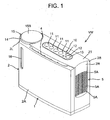
- FIG. 1 is an appearance diagram of an air bacteria removal device VW according to one embodiment of the present invention
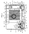
- FIG. 2 is a diagram of a vertical side surface view of the air bacteria removal device VW of FIG. 1 as viewed from one surface side (front surface side)
- FIG. 3 is a diagram of a vertical side surface of the device VW of FIG. 1 as viewed from another surface side (back surface side).
- reference numeral 1 is a main body of the air bacteria removal device VW according to the present embodiment
- 2 is a main body cover which is attached to the main body 1 and which covers a bacteria removal element 8, a filter 7, an air blower 20 and the like mounted on the main body 1 as described later.
- the main body cover 2 includes a top plate 2T and four panels (a front panel 2A, a back panel 2B, a side panel 2R and a side panel 2L) extending in a vertical direction from an outer peripheral edge of this top plate 2T.
- an operating section 10 which includes a plurality of (four in the embodiment) operation switches 11 for control, display means 12 constituted of a plurality of (two in the embodiment) LED lamps, and a power switch 13. Moreover, a suction port 4 for sucking air in a room as a bacteria removal space into the air bacteria removal device VW (into the main body cover 2) is formed between one end portion (a front end portion in FIG. 1) of the top plate 2T and an upper end portion of the front panel 2A.
- the side panel 2R positioned on one end side (on a right end side of the front panel 2A and the back panel 2B in FIGS.
- This exhaust port 5 is constituted of a large number of small holes 5A ... formed at the side panel 2R along a vertical direction thereof.
- a hole 14 extending through the top plate 2T in the vertical direction (an upward/downward direction) is formed on the other end side (the side panel 2L side) of the top plate 2T of the main body cover 2.
- This hole 14 is a hole for a water supply tank 15.
- an upper surface 15B of the water supply tank 15 is positioned in this hole 14.
- the front panel 2A of the main body cover 2 is provided with a water amount confirming window 16 for confirming a water level of water (tap water as one example of water including at least chloride ions) stored in the water supply tank 15. With this window 16 for confirming the water amount, the amount of the water in the water supply tank 15 can be confirmed without removing the main body cover 2.
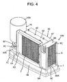
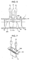
- FIG. 4 shows an inner constitution diagram of the air bacteria removal device VW in a state in which the main body cover 2 is removed from the main body 1
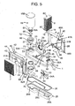
- FIG. 5 shows an exploded diagram of the air bacteria removal device VW of FIG. 4, respectively.
- the main body 1 of the air bacteria removal device VW is a frame body including a receiving plane 1A and a wall surface 1B extending in the vertical direction (a downward direction) from an outer peripheral edge of this receiving plane 1A, and a lower end of the wall surface 1B is provided with an expanded portion 1C expanded externally from the wall surface 1B.
- An outer periphery of the wall surface 1B is formed so as to be substantially the same as an inner periphery of the main body cover 2, and an outer periphery of the expanded portion 1C is set so as to be larger than that of the wall surface.
- the communication hole 30 formed at one end portion of the receiving plane 1A is a hole for attaching the bacteria removal element 8 to one end portion of the main body 1, and an engagement portion 30A raised upwards from the receiving plane 1A is formed at the periphery of the communication hole.
- the communication hole 33 formed at the other end portion of the receiving plane 1A is a hole for attaching the water supply tank 15 to the other end portion of the main body 1, and an engagement portion 33A raised upwards from the receiving plane 1A is also formed at the periphery of this communication hole 33.
- the communication holes 31 and 32 at the center of the receiving plane 1A are formed adjacent to each other, the communication hole 31 is disposed on a wall surface 1B side, and the communication hole 32 is disposed on a front panel 2A side. Electrodes 17, 18 described later are attached to the communication hole 31, and one end of an air passing tube 37 described later is similarly connected to the communication hole 32.
- This electrolytic tank tray 25 is a longitudinal water receiving member including the side of one end portion 25A having a space in which a sufficient capacity is secured, the side of the other end portion 25B in which a sufficient capacity is similarly secured, and the center 25C which allows the one end portion 25A side and the other end portion 25B side to communicate with each other and whose one side (front side) is largely bored and which has a small inner capacity and a small shape.
- An opening edge of an upper end of the electrolytic tank tray 25 is fitted into the engagement portion 25D formed at the bottom surface of the receiving plane 1A of the main body 1. Specifically, in a state in which a packing 26 as a seal member is attached to the whole periphery of the opening edge of the upper end of the electrolytic tank tray 25, the electrolytic tank tray 25 is inserted into the wall surface 1B from the downside of the expanded portion 1C of the main body 1. Then, when the electrolytic tank tray 25 is inserted into a predetermined attachment position, the upper end opening fits into the engagement portion 25D, whereby the electrolytic tank tray 25 is attached to the main body 1.
- the capacity of the electrolytic water to be stored at the center of the water storage tank 9 is necessarily reduced.
- the bacteria removal element 8 is attached to the center in the water storage tank 9, that is, one end portion of the main body 1, and the water supply tank 15 is attached to the other end portion as described above, a pair of electrodes 17, 18 (an electrolytic unit) described above are disposed in the water storage tank 9 between this bacteria removal element 8 and the water supply tank 15.
- the electrodes 17, 18 electrochemically treat (electrolyze) the tap water stored in the water storage tank 9 to produce the electrolytic water.
- the active oxygen species include oxygen molecules having oxidation activity higher than that of usual oxygen, and related substances. It is assumed that active oxygen in a so-called narrow sense, for example, super oxide anion, singlet oxygen, hydroxyl radical or hydrogen peroxide, and active oxygen in a so-called broad sense, for example, ozone or hypohalogen acid are included.
- the electrodes 17, 18 are electrode plates each including a base made of titanium (Ti) and a coat layer of iridium (Ir) or platinum (Pt). As a current value to be applied to these electrodes 17, 18, assuming that a current density is 20 milliamperes (mA)/square centimeter (cm 2 ), a predetermined floating residual chlorine concentration (e.g., 1 milligram (mg)/liter (1) is produced.
- a predetermined floating residual chlorine concentration e.g., 1 milligram (mg)/liter (1) is produced.
- peripheries of the electrodes 17, 18 are fixed to an electrode fixing plate 54 so that the surfaces of both electrode plates are arranged so as to face each other with a predetermined space disposed therebetween.
- An upper end of this electrode fixing plate 54 is provided with a protruding portion 54A having substantially the same shape as that of the communication hole 31 of the main body 1, and the protruding portion 54A engages with an inner surface of the communication hole 31 to attach the plate to the main body 1.
- the air blower 20 is arranged so that the fan air suction port 23A is positioned on the front panel 2A side and the fan exhaust port 23B is positioned on the side panel 2R side, and the air blower is attached to the upper surface of the center of the receiving plane 1A of the main body 1 in a state in which an outer periphery of the air blower is surrounded with a fixing plate (a first fixing plate 40 and a second fixing plate 45).
- the second fixing plate 45 includes a flat surface 46 disposed on the other surface side (the back surface side) of the air blower 20, a peripheral wall portion 47 extending from an outer peripheral edge of the flat surface 46 on the air blower 20 side, and a holding surface 8B which extends horizontally to the flat surface 46 from one end side (the right end side in FIG. 5) of the flat surface 46 and which fixes the bacteria removal element 8.
- a flat surface 46 disposed on the other surface side (the back surface side) of the air blower 20 side
- a peripheral wall portion 47 extending from an outer peripheral edge of the flat surface 46 on the air blower 20 side
- a holding surface 8B which extends horizontally to the flat surface 46 from one end side (the right end side in FIG. 5) of the flat surface 46 and which fixes the bacteria removal element 8.
- the convex portion 47A to be engaged with the concave portion 42A is formed. Over one end side (a left end side in FIG. 3, a right end side in FIG.
- a bacteria removal element 8 side of the side (the air blower 20 side) on which the peripheral wall portion 47 of the flat surface 46 extends, the one end side constituting the bacteria removal element 8 side from a portion where the fan exhaust port 23B is positioned in a case where the air blower 20 is arranged in the fixing plates 40, 45, dividing plates 48A, 48B are attached which form an air duct 48 which supplies the air discharged from the fan exhaust port 23B to the bacteria removal element 8. Furthermore, a fin 49 for adjusting a flow direction of the air discharged from the fan exhaust port 23B is attached to the attached lower dividing plate 48B.
- the hole 41A formed at the flat surface 41 and the fan air suction port 23A of the fan casing 23 of the air blower 20 are aligned to arrange the first fixing plate 40.
- the second fixing plate 45 is arranged from the other end side of the air blower 20.
- the tip end of the peripheral wall portion 47 of the second fixing plate 45 is arranged so as to abut on the tip end of the peripheral wall portion 42 of the first fixing plate 40, the convex portion 47A of the flat surface 46 is fitted into the concave portion 42A formed above the peripheral wall portion 42, whereby the air blower 20 is surrounded in a space formed by the fixing plates 40, 45.
- both the fixing plates 40, 45 are fixed with screws from the back surface side of the second fixing plate 45, and further both the fixing plates 40, 45 are fixed to the main body 1 with screws or the like, so that the air blower can be mounted on the main body 1.
- the filter 7 is arranged with a predetermined space from the front panel 2A on an inner side of the front panel 2A, and the suction port 4 is positioned on an upper front surface side of the filter 7, that is, on the front panel side. Therefore, when the air blower 20 is operated, the air sucked from the suction port 4 passes through a gap formed between the front panel 2A and the filter 7, passes through the filter 7 disposed at the front surface of the air blower 20, and is then sucked into the air blower 20.
- the bacteria removal element 8 is subjected to a hydrophilic treatment to improve hidrophilicity to the electrolytic water, whereby a water retaining property (wettability) of the bacteria removal element 8 with respect to the electrolytic water is improved, and the air passed through the bacteria removal element 8 can be brought into contact with the electrolytic water for a long time. Furthermore, plate members having excellent resistance to corrosion are attached to an upper surface and a bottom surface of this bacteria removal element 8.
- this bacteria removal element 8 is integrally provided with two cylindrical water absorption rods 19.
- the water absorption rods 19, 19 are water absorption members for sucking the electrolytic water to supply the water to the bacteria removal element 8, and are formed of a material having an excellent water absorption property, for example, non-woven cloth made of acryl fiber, polyester fiber or the like, a sponge or the like.
- One end portions (upper end portions) of the water absorption rods 19 are disposed so as to abut on a plate member 8C of an upper surface. Then, the rods extend through the bacteria removal element 8 in the vertical direction (the downward direction) from this one end portion, and then exit from the other end (the lower end) of the bacteria removal element 8, and the other end portions (the lower end portions) of the rods are constituted so as to protrude from'a bottom portion (the plate member 8C at the bottom surface) of the bacteria removal element 8. That is, the plate member 8C at the bottom surface is provided with holes (not shown) through which the water absorption rods 19 extend, and the other ends of the water absorption rods 19 protrude from the holes to further extend downwards.
- the bacteria removal element 8 is detachably attached to the inside of the communication hole 30 formed at the receiving plane 1A of the main body 1.
- a packing 34 as a seal member is attached to the whole peripheral edge of the upper end of the engagement portion 30A formed at the periphery of the communication hole 30 of the receiving plane 1A, and an element receiver 35 is mounted from the upside of the packing.
- the bacteria removal element 8 integrated with the water absorption rods 19 is inserted into a space between the holding surface 8A of the first fixing plate 40 and the holding surface 8B of the second fixing plate from the upside of the element receiver 35, and the bottom surface of the plate member 8C of the bacteria removal element 8 is mounted on the upper surface of the element receiver 35.
- the bacteria removal element 8 is mounted on the main body 1.
- the communication hole 30 is closed with the bacteria removal element 8 via the packing 34 and the element receiver 35, and hermetically sealed, and the water storage tank 9 is therefore brought into a sealed or semi-sealed state.
- the water absorption rods 19 enter the water storage tank 9, and the other end portions of the rods are submerged into the electrolytic water.
- the water supply tank 15 is a cartridge type tank for refilling the water storage tank 9 with the tap water.
- the water supply tank 15 is formed into such a shape so that the tank rises in the vertical direction from a circular opening 15A formed at a bottom surface thereof, then expands externally, and further rises in the vertical direction, and an upper end of the tank is closed with the upper surface 15B having a diameter larger than that of the opening 15A. Then, water is supplied inwardly from the opening 15A formed at the lower end of the tank, and the water storage tank 9 is refilled with the tap water from this opening 15A via a water passing port 64 formed at a cap receiver 62 described later.
- an outer peripheral surface of the water supply tank 15 on an opening 15A side is provided with a thread ridge 61 to be engaged with a thread groove (not shown) formed on an inner surface side of a cap 60.
- the cap 60 holds the water supply tank on the opening 15A side, and detachably attaches the water supply tank 15 to the communication hole 33 formed on the other end side of the receiving plane 1A of the main body 1 in the sealed manner together with the cap receiver 62 and packing 65, 66 as a seal member.
- a cylindrical water stop portion 60A which rises along an inner surface of the opening 15A of the water supply tank 15 is formed.
- a water stop valve 72 is disposed on the upside of this water stop portion 60A.
- This water stop valve 72 is a valve device for avoiding water leakage from the water supply tank 15 in a case where the water supply tank is carried or the water supply tank 15 is attached to the main body 1.
- An outer diameter of this water stop valve 72 is set to be smaller than an inner diameter of the water supply tank 15 around the water supply tank 15, and larger than an inner diameter of the water stop portion 60A.
- a shaft component 73 of the water stop valve is attached to the center of the water stop valve 72, and a lower end of the shaft component is attached to the cap receiver 62.
- the water stop valve 72 is positioned with a predetermined gap from the water stop portion 60A above the water stop portion 60A. Therefore, as shown by arrows in FIG. 3, the tap water in the water supply tank 15 passes through this gap to reach the opening 15A, and is supplied into the water storage tank 9 from this opening 15A via the water passing port 64 of the cap receiver 62.
- valve device 70 in the state in which the water supply tank 15 is attached to the main body 1, the water supply from this water supply tank 15 into the water storage tank 9 is controlled by a valve device 70.
- the valve device 70 of the present embodiment is constituted of a float valve 71 which controls the water supply'from the water supply tank 15 in accordance with a water level of the electrolytic water in the water storage tank 9.
- a float to be constantly positioned on a water surface of the electrolytic water in the water storage tank 9 is attached to one end of a main body constituted of a plate member having a longitudinal shape, and the other end of the main body is tiltably supported by the bottom surface of the cap receiver 62.
- the float valve 71 can tilt in the upward/downward direction in accordance with the water level of the electrolytic water in the water storage tank 9 where the float at the one end of the float valve 71 is positioned.
- the valve device 70 having the above-mentioned constitution, when the electrolytic water in the water storage tank 9 is stored up to a predetermined water level above the other end portions (the lower end portions) of the water absorption rods 19, the water passing port 64 is closed with the upper surface of the main body of the float valve 71, and the water supply from the water supply tank 15 to the water storage tank 9 is securely prohibited. Furthermore, when the water level of the electrolytic water in the water storage tank 9 drops below the predetermined water level, the water passing port 64 is opened by a tilt operation of the float valve 71 to supply the water into the water storage tank 9. It is to be noted that the water level at which this float valve 71 opens the water passing port 64 is a water level at which the other end portions (the lower end portions) of the water absorption rods 19 are submerged into the electrolytic water in the water storage tank 9.
- the water passing port 64 is securely closed with the float valve 71 to prohibit the water supply from the water supply tank 15.
- the water absorption rods 19 can constantly be submerged into the electrolytic water by the valve device 70 of the present embodiment in this manner, the supply of the electrolytic water to the bacteria removal element 8 can firmly be secured.
- this float valve 71 is constituted so that when the main body 1 tilts, the water supply from the water supply tank 15 into the water storage tank 9 is securely prohibited. That is, when one end side of the main body 1 on the bacteria removal element 8 side tilts high, the other end side of the main body 1 on a water supply tank 15 side tilts low, and the water surface in the water storage tank 9 on the water supply tank 15 side rises, and needless to say, the float valve 71 closes the water passing port 64.
- the present float valve 71 is constituted so that even when the other end side of the main body 1 on the water supply tank 15 side tilts high and the water level of the opening 15A of the water supply tank 15 drops, the water supply into the water storage tank 9 can be prohibited.
- the water in the water storage tank 9 moves toward the bacteria removal element 8, but it is assumed that the water storage tank 9 has the sealed structure or the semi-sealed structure (the semi-sealed structure in the present embodiment) as described above. Therefore, since the electrolytic water scarcely leaks from the water storage tank 9, a constant water level can be kept in the water storage tank 9 on the water supply tank 15 side. In consequence, the state in which the float valve 71 closes the water passing port 64 can be maintained.
- a partition wall 50 is disposed which separates an upper space around the electrodes 17, 18 from another part.
- the partition wall 50 extends in the vertical direction from the bottom surface of the receiving plane 1A of the main body 1 in the water storage tank 9, and a tip end of the partition wall is disposed in the electrolytic water stored in the water storage tank 9. The tip end is positioned with a sufficient gap from the upper surface of the electrolytic tank tray 25 constituting the bottom surface of the water storage tank 9 so that there is not any trouble in circulation of the electrolytic water.
- the air passing tube 37 is a gas release device for releasing a gas from the water storage tank 9 having the sealed structure or the semi-sealed structure.
- the air passing tube 37 of the present embodiment extends from the water storage tank 9 via one end thereof which opens (an inlet of the gas release device) in the space above the water surface of the electrolytic water of the water storage tank 9 surrounded with the partition wall 50 in the water storage tank 9, and passes around the air blower 20. Afterward, the other end of the tube opens (an outlet of the gas release device) in the vicinity of an upper end of the bacteria removal element 8 on a side opposite to the side panel 2R.
- the tap water in the water storage tank 9 is electrolyzed as described above to produce the sterile water (the electrolytic water) including hypochlorous acid (HC10), but a gas (hydrogen, oxygen or the like) is generated in the electrodes 17, 18 in a process to produce this electrolytic water.
- the water storage tank 9 of the present invention has the sealed structure or the semi-sealed structure, and hence the generated gas is stored on the water surface of the electrolytic water in the water storage tank 9. Then, a pressure in the water storage tank 9 gradually increases owing to the generated and accumulated gas, so that the water storage tank 9 might be deformed or broken, and the stored electrolytic water might leak in the worst case.
- the air passing tube 37 is disposed as in the present invention, whereby the gas generated in the electrodes 17, 18 can be discharged from the water storage tank 9 via the air passing tube 37.
- peripheries of the electrodes 17, 18 are surrounded with the partition wall 50, separated from the other part, and especially separated from the space above the water surface of the electrolytic water of the water storage tank 9 outside the partition wall 50, whereby the gas generated in the electrodes 17, 18 gathers in the space above the water surface of the electrolytic water surrounded with the partition wall 50.
- the opening of one end of the air passing tube 37 is disposed in this space, so that the air passing tube 37 can smoothly trap the gas generated in the electrodes 17, 18 to discharge the gas from the water storage tank 9 via the other end that opens in the vicinity of the upper end of the bacteria removal element 8 on the side opposite to the side panel 2R.
- a disadvantage that the pressure in the water storage tank 9 increases owing to the generated gas can be eliminated in advance.
- the air blower 20 is started.
- the air path is formed in which the air of the room (in the bacteria removal space) sucked from the suction port 4 successively passes through the filter 7, the air blower 20 and the bacteria removal element 8, and is discharged from the exhaust port 5. That is, the air in the room sucked from the suction port 4 passes through the gap between the front panel 2A of the main body cover 2 and the filter 7, and passes through the filter 7. At this time, dust included in the air is trapped by the filter 7. Since the filter 7 of the present embodiment has a deodorizing effect in addition to a dust collecting effect, odor is removed from the air when passing through the filter 7.
- the air from which the dust and the odor have been removed with the filter 7 is sucked into the air blower 20 from the fan air suction port 23A formed on the front surface side of the fan casing 23 in the axial direction in which the air blowing fan 21 rotates. Then, the air is discharged from the fan exhaust port 23B formed at the lower portion of the fan casing 23 on the one end side in the radial direction of the air blowing fan 21, and passed and supplied to the bacteria removal element 8 via the air duct 48 formed on the exhaust side of this fan exhaust port 23B.
- hypochlorous acid has a function of destroying and eliminating (removing) influenza virus surface protein (spike) which is indispensable for infection of influenza in a case where, for example, influenza virus invades the air in the room. In a case where this protein is destroyed, the influenza virus does not bond to a receptor of an infectee, which is necessary for the infection of the virus. In consequence, the infection is inhibited.
- the air in the room is supplied to the bacteria removal element 8 and brought into contact with the electrolytic water supplied to the bacteria removal element 8 in this manner, so that the bacteria can be removed from the air by hypochlorous acid included in the electrolytic water.
- the air which has passed through the bacteria removal element 8 and from which the bacteria has been removed is discharged to the outside (into the room) from the exhaust port 5 of the side panel 2R disposed on the one end side of the bacteria removal element 8.
- the electrolytic water electrolyzed, generated and stored in the water storage tank 9 by the energizing of the electrodes 17, 18 is quickly supplied to the bacteria removal element 8 via the water absorption rods 19 by use of a capillary phenomenon, and the electrolytic water is brought into contact with the air passed from the air blower 20 in the bacteria removal element 8, so that the bacteria can efficiently be removed from the air.
- the electrolytic water stored in the water storage tank 9 can be supplied to the bacteria removal element 8 without disposing any electrolytic water drip means such as a special pump mechanism as in the conventional example, the structure can be simplified, and the device can be miniaturized. Since the pump mechanism is not required, any power for driving a pump is not consumed, and hence power consumption can be reduced.
- the water storage tank 9 in which the electrolytic water is stored is constituted by attaching the tank to the main body 1 via the packing 26 at the upper end opening edge of the electrolytic tank tray 25 in the sealed manner, and the communication holes 30, 31, 32 and 33 formed at the receiving plane 1A of the main body 1 are similarly sealed and closed with the bacteria removal element 8 integrated with the water absorption rods 19, the electrode fixing plate 54 which fixes the electrodes 17, 18, the air passing tube 37 and the water supply tank 15, respectively. Therefore, the water storage tank 9 has the sealed structure or the semi-sealed structure, sealability of the water storage tank 9 is secured, and the water does not easily leak from the structure.
- a structure has to be constituted in which at least the electrolytic water excessively supplied to the gas-liquid contact member can be collected. Therefore, there has been a problem that the structure is complicated, the device is enlarged and costs increase.
- the electrolytic water in the water storage tank 9 is supplied using the capillary phenomenon, unlike the conventional example, the electrolytic water supplied to the bacteria removal element 8 does not have to be collected, so that the path of the water and the structure can be simplified to miniaturize the device. Furthermore, the water storage tank 9 can easily be formed into the sealed structure, and the sealability of the water storage tank 9 can further be improved.
- the present invention can be mounted in a vehicle such as a car or a train.
- the air bacteria removal device of the present invention is mounted in the vehicle in this manner and the air bacteria removal device is used on conditions that the device tilts during running along a slope or the like, such a structure is more effective.
- the bacteria removal element 8 and the water absorption rods 19 are integrated and detachably attached to the main body 1, so that the bacteria removal element 8 and the water absorption rods 19 can freely be removed from the main body.
- the dust attached to the bacteria removal element 8 and the water absorption rods 19 from the passed air and a scale in the electrolytic water can be cleaned. After the cleaning, the element and the rods can easily be mounted on the main body 1. In consequence, daily maintenance is easily performed.
- the filter 7 is disposed in the air path on the windward side from the bacteria removal element 8, the dust in the air is removed, and the air is then supplied to the bacteria removal element 8, so that the attachment of the dust to the bacteria removal element 8 can be eliminated or inhibited. Furthermore, since the filter 7 of the present embodiment also has the deodorizing function, the odor in the air can be removed.
- the air blower 20 is constituted of the sirocco fan for sucking the air from the direction of the axis around which the air blowing fan 21 rotates to discharge the air in the radial direction, whereby the bacteria removal element 8 is arranged in the axial direction around which the air blowing fan 21 of the air blower 20 rotates. Therefore, the water storage tank 9 also has a longitudinal shape, and the whole device can be slimmed. In consequence, while the miniaturization of the device is achieved, it is possible to secure a series of operations of sucking the outside air (the air in the room) to blow the air to the bacteria removal element 8, refilling the water storage tank 9 with the tap water from the water supply tank 15, and electrolyzing the water to supply the water to the bacteria removal element 8.
Landscapes
- Engineering & Computer Science (AREA)
- Health & Medical Sciences (AREA)
- Chemical & Material Sciences (AREA)
- Combustion & Propulsion (AREA)
- Mechanical Engineering (AREA)
- General Engineering & Computer Science (AREA)
- Epidemiology (AREA)
- Life Sciences & Earth Sciences (AREA)
- Animal Behavior & Ethology (AREA)
- General Health & Medical Sciences (AREA)
- Public Health (AREA)
- Veterinary Medicine (AREA)
- Water Treatment By Electricity Or Magnetism (AREA)
- Disinfection, Sterilisation Or Deodorisation Of Air (AREA)
Applications Claiming Priority (1)
| Application Number | Priority Date | Filing Date | Title |
|---|---|---|---|
| JP2006294164A JP2008110011A (ja) | 2006-10-30 | 2006-10-30 | 空気除菌装置 |
Publications (2)
| Publication Number | Publication Date |
|---|---|
| EP1918652A2 true EP1918652A2 (de) | 2008-05-07 |
| EP1918652A3 EP1918652A3 (de) | 2010-05-26 |
Family
ID=38988351
Family Applications (1)
| Application Number | Title | Priority Date | Filing Date |
|---|---|---|---|
| EP07021198A Withdrawn EP1918652A3 (de) | 2006-10-30 | 2007-10-30 | Vorrichtung zum Entfernen von Bakterien aus der Luft |
Country Status (5)
| Country | Link |
|---|---|
| US (1) | US20080128272A1 (de) |
| EP (1) | EP1918652A3 (de) |
| JP (1) | JP2008110011A (de) |
| KR (1) | KR20080039260A (de) |
| CN (1) | CN101173808A (de) |
Cited By (1)
| Publication number | Priority date | Publication date | Assignee | Title |
|---|---|---|---|---|
| WO2018197826A3 (en) * | 2017-04-25 | 2019-03-28 | Protex Hygiene Limited | IMPROVEMENTS RELATING TO DISINFECTION OF AIR SPACE |
Families Citing this family (12)
| Publication number | Priority date | Publication date | Assignee | Title |
|---|---|---|---|---|
| JP5066053B2 (ja) * | 2008-10-21 | 2012-11-07 | パナソニック株式会社 | 脱臭装置 |
| US9533897B2 (en) * | 2013-03-12 | 2017-01-03 | Radical Waters International Ltd. | Method for electro-chemical activation of water |
| CN103216896A (zh) * | 2013-04-15 | 2013-07-24 | 欧坤 | 多功能空气治理机 |
| CN104121652B (zh) * | 2013-04-27 | 2018-10-16 | 广东松下环境系统有限公司 | 加湿装置 |
| CN106114146A (zh) * | 2016-07-28 | 2016-11-16 | 太仓文广汇清洁设备有限公司 | 一种车载空气净化器 |
| CN106985639A (zh) * | 2017-03-08 | 2017-07-28 | 珠海爱琴海智能电器有限公司 | 一种多功能车载空气净化器 |
| CN207445856U (zh) * | 2017-09-19 | 2018-06-05 | 京东方科技集团股份有限公司 | 一种空气净化器 |
| JP7228140B2 (ja) * | 2019-10-03 | 2023-02-24 | 学校法人東邦大学 | 空間除菌清浄化装置 |
| WO2021066203A1 (ja) * | 2019-10-03 | 2021-04-08 | 学校法人 東邦大学 | 空間除菌清浄化装置 |
| CN110671761A (zh) * | 2019-11-07 | 2020-01-10 | 深圳市康弘环保技术有限公司 | 空气净化装置 |
| WO2023023910A1 (zh) * | 2021-08-23 | 2023-03-02 | 卡富环球有限公司 | 具有杀菌功能的电解器具和空气净化装置 |
| KR102400096B1 (ko) * | 2021-11-29 | 2022-05-23 | 주식회사 한새 | 살균장치 |
Family Cites Families (9)
| Publication number | Priority date | Publication date | Assignee | Title |
|---|---|---|---|---|
| JPH0574541U (ja) * | 1992-03-16 | 1993-10-12 | 正義 前川 | 脱臭用フィルター |
| JP2000257914A (ja) * | 1999-03-05 | 2000-09-22 | Techno Ryowa Ltd | 強酸性水を用いた除菌空調システム |
| US6394427B1 (en) * | 2000-09-13 | 2002-05-28 | Research Products Corp. | Drainless humidifier with water level sensing |
| JP2002181358A (ja) * | 2000-10-04 | 2002-06-26 | Denso Corp | 加湿装置および加湿装置付き空調装置 |
| US7754157B2 (en) * | 2002-07-08 | 2010-07-13 | Panasonic Corporation | Humidifier |
| JP4401695B2 (ja) * | 2002-07-08 | 2010-01-20 | パナソニック株式会社 | 加湿装置 |
| JP4239692B2 (ja) * | 2003-06-04 | 2009-03-18 | パナソニック電工株式会社 | 空気清浄機 |
| JP4347012B2 (ja) * | 2003-10-02 | 2009-10-21 | 株式会社サンシ−ル | 空気清浄化装置 |
| JP4549204B2 (ja) * | 2004-07-21 | 2010-09-22 | 三洋電機株式会社 | 加湿器 |
-
2006
- 2006-10-30 JP JP2006294164A patent/JP2008110011A/ja active Pending
-
2007
- 2007-10-24 US US11/976,440 patent/US20080128272A1/en not_active Abandoned
- 2007-10-29 KR KR1020070108609A patent/KR20080039260A/ko not_active Ceased
- 2007-10-30 EP EP07021198A patent/EP1918652A3/de not_active Withdrawn
- 2007-10-30 CN CNA2007101848484A patent/CN101173808A/zh active Pending
Cited By (1)
| Publication number | Priority date | Publication date | Assignee | Title |
|---|---|---|---|---|
| WO2018197826A3 (en) * | 2017-04-25 | 2019-03-28 | Protex Hygiene Limited | IMPROVEMENTS RELATING TO DISINFECTION OF AIR SPACE |
Also Published As
| Publication number | Publication date |
|---|---|
| JP2008110011A (ja) | 2008-05-15 |
| CN101173808A (zh) | 2008-05-07 |
| KR20080039260A (ko) | 2008-05-07 |
| US20080128272A1 (en) | 2008-06-05 |
| EP1918652A3 (de) | 2010-05-26 |
Similar Documents
| Publication | Publication Date | Title |
|---|---|---|
| US20080128272A1 (en) | Air Bacteria Removal Device | |
| US7857897B2 (en) | Air filtering apparatus | |
| US7896947B2 (en) | Air filtering apparatus | |
| CN101881501B (zh) | 自动清洗装置的清洗液储存箱及具有该储存箱的空调机 | |
| US7850768B2 (en) | Air filtering apparatus having scale removal detecting mechanism | |
| JP5241135B2 (ja) | 空気除菌装置 | |
| JP4753823B2 (ja) | 空気除菌装置 | |
| JP4740080B2 (ja) | 空気除菌装置 | |
| JP2012042132A (ja) | 加湿機 | |
| JP2008183182A (ja) | 空気除菌装置 | |
| JP5340856B2 (ja) | 空気除菌装置 | |
| JP2011137605A (ja) | 加湿機 | |
| EP1798493A2 (de) | Luftfilterungsvorrichtung | |
| CN101532711A (zh) | 加湿器、空气净化器及电解水单元 | |
| JP4781288B2 (ja) | 空気除菌装置の洗浄方法、及び、空気除菌装置 | |
| JP2006006563A (ja) | ミスト発生装置および空気調和機 | |
| EP1891982A2 (de) | Luftfiltervorrichtung mit Mechanismus zur Entfernung von Fremdstoffen | |
| EP1953462A2 (de) | Luftfilterungsvorrichtung | |
| JP4878850B2 (ja) | 空気除菌装置 | |
| JP7228140B2 (ja) | 空間除菌清浄化装置 | |
| JP4878836B2 (ja) | 床置き式空気除菌装置 | |
| JP2003056869A (ja) | 加湿機 | |
| JP5305563B2 (ja) | 空気除菌装置 | |
| JP4721921B2 (ja) | 空気除菌装置 | |
| JP4744381B2 (ja) | 空気除菌装置 |
Legal Events
| Date | Code | Title | Description |
|---|---|---|---|
| PUAI | Public reference made under article 153(3) epc to a published international application that has entered the european phase |
Free format text: ORIGINAL CODE: 0009012 |
|
| AK | Designated contracting states |
Kind code of ref document: A2 Designated state(s): AT BE BG CH CY CZ DE DK EE ES FI FR GB GR HU IE IS IT LI LT LU LV MC MT NL PL PT RO SE SI SK TR |
|
| AX | Request for extension of the european patent |
Extension state: AL BA HR MK RS |
|
| PUAL | Search report despatched |
Free format text: ORIGINAL CODE: 0009013 |
|
| AK | Designated contracting states |
Kind code of ref document: A3 Designated state(s): AT BE BG CH CY CZ DE DK EE ES FI FR GB GR HU IE IS IT LI LT LU LV MC MT NL PL PT RO SE SI SK TR |
|
| AX | Request for extension of the european patent |
Extension state: AL BA HR MK RS |
|
| STAA | Information on the status of an ep patent application or granted ep patent |
Free format text: STATUS: THE APPLICATION HAS BEEN WITHDRAWN |
|
| 18W | Application withdrawn |
Effective date: 20101125 |