EP1918482A2 - Befestigungssystem für tafelförmige Paneele - Google Patents
Befestigungssystem für tafelförmige Paneele Download PDFInfo
- Publication number
- EP1918482A2 EP1918482A2 EP07020876A EP07020876A EP1918482A2 EP 1918482 A2 EP1918482 A2 EP 1918482A2 EP 07020876 A EP07020876 A EP 07020876A EP 07020876 A EP07020876 A EP 07020876A EP 1918482 A2 EP1918482 A2 EP 1918482A2
- Authority
- EP
- European Patent Office
- Prior art keywords
- fastening system
- layer
- spring
- profiles
- holding profiles
- Prior art date
- Legal status (The legal status is an assumption and is not a legal conclusion. Google has not performed a legal analysis and makes no representation as to the accuracy of the status listed.)
- Granted
Links
- 230000005489 elastic deformation Effects 0.000 claims abstract description 4
- 239000010410 layer Substances 0.000 claims description 37
- 230000013011 mating Effects 0.000 claims description 11
- 239000000835 fiber Substances 0.000 claims description 6
- 239000012790 adhesive layer Substances 0.000 claims description 4
- 239000002131 composite material Substances 0.000 claims description 4
- 229910000679 solder Inorganic materials 0.000 claims description 3
- 239000011521 glass Substances 0.000 claims description 2
- 239000002184 metal Substances 0.000 claims description 2
- 239000002245 particle Substances 0.000 claims description 2
- 239000004576 sand Substances 0.000 claims description 2
- 239000004575 stone Substances 0.000 claims description 2
- 230000000717 retained effect Effects 0.000 abstract 1
- 238000005452 bending Methods 0.000 description 3
- 238000003780 insertion Methods 0.000 description 3
- 230000037431 insertion Effects 0.000 description 3
- 244000144992 flock Species 0.000 description 2
- 238000005352 clarification Methods 0.000 description 1
- 230000000295 complement effect Effects 0.000 description 1
- 238000010276 construction Methods 0.000 description 1
- 230000007423 decrease Effects 0.000 description 1
- 230000000694 effects Effects 0.000 description 1
- 210000003746 feather Anatomy 0.000 description 1
- 238000009434 installation Methods 0.000 description 1
- 238000009413 insulation Methods 0.000 description 1
- 229920001296 polysiloxane Polymers 0.000 description 1
Images

Classifications
-
- E—FIXED CONSTRUCTIONS
- E04—BUILDING
- E04F—FINISHING WORK ON BUILDINGS, e.g. STAIRS, FLOORS
- E04F15/00—Flooring
- E04F15/02—Flooring or floor layers composed of a number of similar elements
-
- E—FIXED CONSTRUCTIONS
- E04—BUILDING
- E04F—FINISHING WORK ON BUILDINGS, e.g. STAIRS, FLOORS
- E04F15/00—Flooring
- E04F15/02—Flooring or floor layers composed of a number of similar elements
- E04F15/04—Flooring or floor layers composed of a number of similar elements only of wood or with a top layer of wood, e.g. with wooden or metal connecting members
-
- E—FIXED CONSTRUCTIONS
- E04—BUILDING
- E04F—FINISHING WORK ON BUILDINGS, e.g. STAIRS, FLOORS
- E04F2201/00—Joining sheets or plates or panels
- E04F2201/01—Joining sheets, plates or panels with edges in abutting relationship
- E04F2201/0153—Joining sheets, plates or panels with edges in abutting relationship by rotating the sheets, plates or panels around an axis which is parallel to the abutting edges, possibly combined with a sliding movement
-
- E—FIXED CONSTRUCTIONS
- E04—BUILDING
- E04F—FINISHING WORK ON BUILDINGS, e.g. STAIRS, FLOORS
- E04F2201/00—Joining sheets or plates or panels
- E04F2201/08—Joining sheets or plates or panels hook and loop-type fastener or similar fixing means
Definitions
- the invention relates to a fastening system for tabular panels, in particular for rectangular floor panels, arranged on narrow sides of the panels holding profiles which extend in the longitudinal direction of the narrow sides and of which oppositely arranged holding profiles match each other such that similar panels are connected to each other, a continuous layer to produce from panels in a laying plane.
- the holding profiles have a surface and a mating surface with a friction-enhancing layer and are formed such that a lateral pulling apart composite holding profiles transversely to the longitudinal extension of the holding profiles and parallel to the laying plane to a relative movement between the surface and counter surface and to a pressure or leads to an increase in pressure between the surface and counter surface.
- one of the support profiles has a groove and a protrusion located therebelow, the upwardly facing top of which slightly rises from the groove to a free end of the protrusion and is provided with a friction-enhancing layer.
- the other retaining profile has an insertable into the groove spring and a recess below the spring.
- a downwardly facing bottom of the recess cooperates in the assembled state of the retaining profiles with the top of the projection, wherein the underside of the recess also has an inclination relative to the laying plane, the inclination the top of the projection corresponds.
- the top of the projection and the underside of the recess thus each form an inclined plane, which is pressed against the other inclined plane in the lateral pulling apart of the holding profiles, which increases the normal force between these two surfaces and thus also the frictional force, which counteracts the lateral sliding apart. Consequently, the top of the projection and the bottom of the recess form the surface and mating surface with the friction-enhancing layer.
- connection of the holding profiles of US 6,808,772 B2 proves to be sufficient, as far as the panels are exactly in one plane and a pulling apart of the holding profiles takes place parallel to the laying plane.
- connection of the holding profiles is often exposed to a multi-axis load.
- a weight force from above on the connection act, by which the composite holding profiles are slightly twisted or tilted about an upper abutment edge of the panels relative to each other. This is possible if the panels are laid on relatively soft subfloors, as they are known for impact sound insulation. With a load from above and the concomitant rotation of the holding profiles thereby reduces the holding force of the holding profiles in a lateral pulling apart.
- the invention is therefore based on the object to provide a fastening system for tabular panels of the type mentioned above, which are simple in construction and offer great security against lateral sliding apart of the holding profiles.
- the fastening system according to claim 1 is characterized in that a rotation of a retaining profile with respect to the composite with the holding profile other holding profile around the upper contact edge, which runs parallel to the longitudinal extension of the holding profiles, counteracts a force through which the surface and the mating surface are held together.
- This force is preferably created by the holding profiles being elastically deformed during relative rotation of the holding profiles about the upper abutment edge.
- the elastic deformation of the holding profiles thereby causes the rotation of the holding profiles not at all or only takes place so that surface and mating surface are not pressed apart by the rotation of the holding profiles and thus the friction between the surface and mating surface, which are overcome in the lateral pulling apart of the holding profiles must, does not fall away.
- the rotation of the holding profile with respect to the other holding profile should be a rotation in which an angle between the tops of the panels of 180 degrees, which is given when the panels are exactly in the laying plane , decreases by a certain amount, for example, 2 degrees to 178 degrees.
- at least one of the two holding profiles is no longer exactly in the laying plane, but is pivoted to this a little upwards around the upper edge of the installation.
- the friction-increasing layer may comprise, for example, a plastic layer and / or an adhesive layer.
- plastic layer or the adhesive layer small particles of sand, stone, glass or metal may be embedded.
- the plastic layer of soft plastic such as silicone.
- the friction-increasing layer is formed as a flocking layer.
- the flocking layer may comprise a base layer and flocking fibers fixed to the base layer at a fixed end and facing away from the base layer with a loose end, the flocking fibers being oriented perpendicular to the base layer or at a non-90 degree angle.
- the orientation of the flock fibers can are suitably adjusted so that the orientation of the flock fibers has a component which precludes a direction of movement when pulling the holding profiles.
- the friction-increasing layer when pulling the holding profiles a greater coefficient of friction than when nesting of the holding profiles.
- Surface and mating surface can each be formed as an inclined plane relative to the laying plane.
- An angle ⁇ between the laying plane and the inclined plane may be only a few degrees, for example 0.5 to 3 degrees.
- a preferred possibility is to arrange the inclined plane so that it is arranged below the upper abutment edge.
- a perpendicular from the upper abutment edge would divide the oblique plane into two areas.
- the solder extends perpendicular to the laying plane, which extends in floor panels in the horizontal.
- the retaining profiles may have a groove with a lower groove side wall and with an upper groove side wall and a spring with a bottom and a top, wherein the spring engages in a groove when the retaining profiles are connected together.
- the upper side of the spring on the upper groove side wall and the underside of the spring on the lower groove side wall abut, so that a weight bearing on the connection weight can be forwarded by the holding profiles without bending moments on the subfloor, as far as it is a rigid Underground acts.
- the lower groove side wall, the upper groove side wall, the underside of the spring and / or the top of the spring can with the surface or the mating surface with form the friction-increasing layer.
- surface and counter surface each form an inclined plane which is inclined to the laying plane.
- the bottom of the spring and the lower groove side wall may be inclined so that when pulling the spring out of the groove, the underside of the spring is pressed against the lower groove side wall.
- the spring is supported with the top of the upper groove inner wall.
- the spring may have a chamfer at a free end.
- the groove may also have a corresponding chamfer.
- the underside of the spring may have a convex curvature and the lower groove inner wall may have a complementarily formed, concave curvature, so that an articulated connection is created about an axis of rotation parallel to the retaining profiles. Due to the curvature, there is an undercut parallel to the laying plane, which helps to prevent the retaining profiles from being pulled apart parallel to the laying plane.
- the convex curvature and the concave curvature follow a section of a circle whose center lies below the upper abutment edge.
- FIG. 1 shows, in cross section, cutouts of a first panel 1 and a second panel 2.
- the panels 1, 2 each have a panel top side 3 and a panel bottom side 4.
- the panel undersides 4 of the panels 1, 2 rest on a subfloor 5.
- a fastening profile 6 is provided which cooperates with a substantially complementary formed retaining profile 6 'of the second panel 2.
- the holding profile 6 has a spring 7 with a bottom 8 and a top 9. While the upper side 9 of the spring 7 extends parallel to the lower floor 5 and thus to a laying plane E in which the panels 1, 2 lie, the underside 8 of the spring has an angle ⁇ which lies in a range between 0 and 3 degrees ,
- the retaining profile 6 For receiving the spring 7 of the retaining profile 6, the retaining profile 6 'has a groove 10 which is bounded by a lower lip 11 and an upper lip 12.
- the lower lip 11 forms a lower groove inner wall 13, while the upper lip 12 defines an upper groove inner wall 14.
- the panels 1, 2 abut an upper (common) abutment edge 15. To ensure this, free spaces 16, 17, 18 are provided, which are set in the assembled position (as shown in Figure 1) between the support profiles 6, 6 '.
- underside 8 of the spring 7 and the lower groove inner wall 13 is inclined by the inclination angle ⁇ to the laying plane E.
- underside 8 of the spring 7 and the lower groove inner wall 13 each form an inclined plane with respect to the laying plane E.
- a friction-increasing layer in the form of a flocking layer 19 is applied between the underside 8 and the lower groove inner wall 13. By this flocking layer 19, the friction between the surfaces 8, 13 is increased.
- the spring 7 at the top 9 a chamfer 20, which facilitates insertion of the spring 7 in the groove 10. Due to the inclination of the bottom 8 of the spring 7 and the inclination of the groove inner wall 13, the spring 7 is compressed during insertion into the groove 10 to a certain extent and the lips 11, 12 pressed apart.
- the fastening profiles 6, 6 ' can be designed so that they lie in the assembled position shown in Figure 1 virtually stress-free together.
- a solder from the upper abutment edge 15 (ie extending perpendicularly from the upper side 3) divides the inclined planes 8, 13 into two areas.
- the lower lip 11 extends beyond the upper abutment edge 15.
- Figure 2 shows the holding profiles 1, 2 in a mutually tilted or rotated position. This tilting or rotation of the panels 1, 2 to each other, for example, arise when a weight G from above on the connection of the holding profiles 6, 6 'loads. The rotation takes place around the upper contact edge 15 of the fastening profiles 6, 6 '.
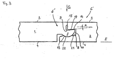
- FIG. 3 shows a further embodiment of the invention.
- Components or features that are similar or identical to corresponding components or features of the embodiment of Figures 1 and 2 are identified with the same reference numerals.
- a top 9 of the spring 7 and cooperating with their upper groove inner wall 14 are formed as inclined planes, between which the friction-increasing flocking layer 19 is located.
Landscapes
- Engineering & Computer Science (AREA)
- Architecture (AREA)
- Civil Engineering (AREA)
- Structural Engineering (AREA)
- Floor Finish (AREA)
- Road Paving Structures (AREA)
Abstract
Description
- Die Erfindung betrifft ein Befestigungssystem für tafelförmige Paneele, insbesondere für rechteckige Fußbodenpaneele, mit an Schmalseiten der Paneele angeordneten Halteprofilen, die sich in Längsrichtung der Schmalseiten erstrekken und von denen gegenüberliegend angeordnete Halteprofile derart zueinander passen, dass gleichartige Paneele miteinander verbindbar sind, um eine zusammenhängende Schicht aus Paneelen in einer Verlegeebene zu erzeugen.
- Aus der
US 6,808,772 B2 ist ein derartiges Befestigungssystem bekannt, wobei die Halteprofile eine Fläche und eine Gegenfläche mit einer reibungserhöhenden Schicht aufweisen und derart ausgebildet sind, dass ein seitliches Auseinanderziehen zusammengesetzter Halteprofile quer zur Längserstreckung der Halteprofile und parallel zur Verlegeebene zu einer Relativbewegung zwischen Fläche und Gegenfläche und zu einem Druck bzw. zu einer Druckerhöhung zwischen Fläche und Gegenfläche führt. In derUS 6,808,772 B2 weist eines der Halteprofile eine Nut und einen darunter angeordneten Vorsprung auf, dessen nach oben gewandte Oberseite von der Nut aus zu einem freien Ende des Vorsprungs leicht ansteigt und mit einer reibungserhöhenden Schicht versehen ist. Das andere Halteprofil weist eine sich in die Nut einsetzbare Feder und eine Aussparung unterhalb der Feder auf. Eine nach unten gewandte Unterseite der Aussparung wirkt im zusammengesetzten Zustand der Halteprofile mit der Oberseite des Vorsprungs zusammen, wobei die Unterseite der Aussparung ebenfalls eine Neigung bezogen auf die Verlegeebene aufweist, die der Neigung der Oberseite des Vorsprungs entspricht. Die Oberseite des Vorsprungs und die Unterseite der Aussparung bilden demnach jeweils eine schiefe Ebene, die beim seitlichen Auseinanderziehen der Halteprofile gegen die andere schiefe Ebene gedrückt wird, was die Normalkraft zwischen diesen beiden Flächen und damit auch die Reibkraft erhöht, die dem seitlichen Auseinanderschieben entgegenwirkt. Folglich bilden Oberseite des Vorsprungs und Unterseite der Aussparung die Fläche und Gegenfläche mit der reibungserhöhenden Schicht. - Die Verbindung der Halteprofile der
US 6,808,772 B2 erweist sich als ausreichend, soweit die Paneele exakt in einer Ebene liegen und ein Auseinanderziehen der Halteprofile parallel zur Verlegeebene erfolgt. Jedoch hat sich in der Praxis gezeigt, dass die Verbindung der Halteprofile oft einer mehrachsigen Belastung ausgesetzt ist. Beispielsweise kann zusätzlich eine Gewichtskraft von oben auf die Verbindung wirken, durch die die zusammengesetzten Halteprofile um eine obere Anlagekante der Paneele relativ zueinander leicht verdreht oder verkantet werden. Möglich ist dies, wenn die Paneele auf vergleichsweise weichen Unterböden verlegt sind, wie sie zur Trittschalldämmung bekannt sind. Bei einer Belastung von oben und der damit einhergehenden Verdrehung der Halteprofile reduziert sich dabei die Haltekraft der Halteprofile bei einem seitlichen Auseinanderziehen. - Der Erfindung liegt daher die Aufgabe zugrunde, ein Befestigungssystem für tafelförmige Paneele der oben genannten Art bereitzustellen, die einfach gebaut sind und eine große Sicherheit gegen ein seitliches Auseinanderschieben der Halteprofile bieten.
- Die der Erfindung zugrunde liegende Aufgabe wird mit der Merkmalskombination gemäß Anspruch 1 gelöst. Bevorzugte Ausführungsbeispiele können den Unteransprüchen entnommen werden.
- Das Befestigungssystem gemäß Anspruch 1 zeichnet sich dadurch aus, dass einer Drehung eines Halteprofils bezogen auf das mit dem Halteprofil zusammengesetzte andere Halteprofil um die obere Anlagekante, die parallel zu der Längserstreckung der Halteprofile verläuft, eine Kraft entgegenwirkt, durch die die Fläche und die Gegenfläche aneinander gehalten werden. Diese Kraft entsteht vorzugsweise dadurch, dass bei Relativverdrehung der Halteprofile um die obere Anlagekante die Halteprofile elastisch verformt werden. Somit kann in einem viel größeren Maße sichergestellt werden, dass sich die Halteprofile seitlich nicht auseinanderziehen lassen, auch wenn dabei ein Gewicht von oben auf die Verbindung der Halteprofile lastet, durch die die Halteprofile um die obere Anlagekante relativ zueinander verschwenkt werden. Die elastische Verformung der Halteprofile bewirkt dabei, dass die Verdrehung der Halteprofile zueinander gar nicht oder nur so stattfindet, dass Fläche und Gegenfläche durch das Verdrehen der Halteprofile nicht auseinandergedrückt werden und damit die Reibung zwischen Fläche und Gegenfläche, die beim seitlichen Auseinanderziehen der Halteprofile überwunden werden muss, nicht wegfällt.
- Zur Klarstellung sei darauf hingewiesen, dass es sich bei der Drehung des Halteprofils bezogen auf das andere Halteprofil um eine Drehung handeln soll, bei der ein Winkel zwischen den Oberseiten der Paneele von 180 Grad, der gegeben ist, wenn die Paneele exakt in der Verlegeebene liegen, sich um ein bestimmtes Maß verringert, beispielsweise um 2 Grad auf 178 Grad. In diesem Fall liegt zumindest eines der beiden Halteprofile nicht mehr exakt in der Verlegeebene, sondern ist zu dieser um die obere Anlagekante ein wenig nach oben geschwenkt.
- Die reibungserhöhende Schicht kann beispielsweise eine Kunststoffschicht und/oder eine Klebstoffschicht umfassen. In der Kunststoffschicht oder der Klebstoffschicht können kleine Partikel aus Sand, Stein, Glas oder Metall eingebettet sein. Beispielsweise kann die Kunststoffschicht aus weichem Kunststoff wie Silikon sein.
- In einem bevorzugten Ausführungsbeispiel ist die reibungserhöhende Schicht als Beflockungsschicht ausgebildet. Die Beflockungsschicht kann eine Basisschicht und Flockfasern umfassen, die an einem festen Ende an der Basisschicht befestigt sind und mit einem losen Ende von der Basisschicht wegzeigen, wobei die Flockfasern zur Basisschicht rechtwinklig oder in einem Winkel ungleich 90 Grad ausgerichtet sind. Die Ausrichtung der Flockfasern kann zweckmäßig so eingestellt werden, dass die Ausrichtung der Flockfasern eine Komponente aufweist, die einer Bewegungsrichtung beim Auseinanderziehen der Halteprofile entgegensteht. Somit weist die reibungserhöhende Schicht beim Auseinanderziehen der Halteprofile einen größeren Reibwert auf als beim Ineinanderschieben der Halteprofile.
- Fläche und Gegenfläche können jeweils als schiefe Ebene bezogen auf die Verlegeebene ausgebildet sein. Ein Winkel α zwischen der Verlegeebene und der schiefen Ebene kann nur einige Grad betragen, beispielsweise 0,5 bis 3 Grad. Beim Auseinanderziehen der Halteprofile werden die ebene Fläche und die ebene Gegenfläche aufgrund der Neigung zur Verlegeebene aneinandergepresst, was die Reibkraft und damit die Haltekraft der Verbindung der Halteprofile erhöht.
- Eine bevorzugte Möglichkeit besteht darin, die schräge Ebene so anzuordnen, dass sie unterhalb der oberen Anlagekante angeordnet ist. In diesem Fall würde ein Lot ausgehend von der oberen Anlagekante die schräge Ebene in zwei Bereiche teilen. Das Lot erstreckt sich dabei senkrecht zur Verlegeebene, die sich bei Fußbodenpaneelen in der Horizontalen erstreckt. Eine derartige Anordnung hat den Vorteil, dass bei einer relativen Drehung der Halteprofile um die obere Anlagekante zumindest Fläche und Gegenfläche in einem der Bereiche der schiefen Ebene aneinandergedrückt werden, was in diesem Bereich zu einer Erhöhung der Reibkraft führt.
- Die Halteprofile können eine Nut mit einer unteren Nutseitenwand und mit einer oberen Nutseitenwand sowie eine Feder mit einer Unterseite und einer Oberseite aufweisen, wobei die Feder in eine Nut greift, wenn die Halteprofile miteinander verbunden sind. Im verbundenen Zustand kann dabei die Oberseite der Feder an der oberen Nutseitenwand und die Unterseite der Feder an der unteren Nutseitenwand anliegen, so dass eine auf der Verbindung lastende Gewichtskraft von den Halteprofilen ohne Biegemomente auf den Unterboden weitergeleitet werden kann, soweit es sich um einen starren Unterboden handelt. Die untere Nutseitenwand, die obere Nutseitenwand, die Unterseite der Feder und/oder die Oberseite der Feder können die Fläche bzw. die Gegenfläche mit der reibungserhöhenden Schicht bilden. Dabei können, wie oben bereits ausgeführt, Fläche und Gegenfläche jeweils eine schiefe Ebene bilden, die zu der Verlegeebene geneigt ist. Beispielsweise können die Unterseite der Feder und die untere Nutseitenwand so geneigt sein, dass beim Herausziehen der Feder aus der Nut die Unterseite der Feder gegen die untere Nutseitenwand gedrückt wird. Die Feder stützt sich dabei mit der Oberseite an der oberen Nutinnenwand ab.
- Um ein Einsetzen der Feder in die Nut zu erleichtern, kann die Feder an einem freien Ende eine Fase aufweisen. Alternativ oder zusätzlich kann die Nut ebenfalls eine entsprechende Fase aufweisen.
- In einem bevorzugten Ausführungsbeispiel kann die Unterseite der Feder eine konvexe Wölbung und die untere Nutinnenwand eine komplementär ausgebildete, konkave Wölbung aufweisen, so dass eine gelenkige Verbindung um eine Drehachse parallel zu den Halteprofilen erzeugt wird. Aufgrund der Wölbung ist ein Hinterschnitt parallel zur Verlegeebene gegeben, der verhindern hilft, dass sich die Halteprofile parallel zur Verlegeebene auseinander ziehen lassen.
- In einem bevorzugten Ausführungsbeispiel folgen die konvexe Wölbung und die konkave Wölbung einem Ausschnitt eines Kreises, dessen Mittelpunkt unterhalb der oberen Anlagekante liegt. Werden nun die Halteprofile um die obere Anlagekante verdreht, wird dabei die Unterseite der Feder gegen die untere Nutinnenwand gedrückt, wobei sowohl die Feder als auch eine untere Lippe, die die Nut begrenzt, elastisch verformt werden. Durch diese elastischen Verformungen wirkt auf die Halteprofile eine Rückstellkraft, durch die die Halteprofile aus der belasteten geneigten Stellung wieder in die Verlegeebene gedreht werden. Dadurch werden Fläche und Gegenfläche aneinander gehalten, wodurch Fläche und Gegenfläche die Haltekraft der Verbindung parallel zur Verlegeebene aufbauen können.
- Anhand von in der Zeichnung dargestellten Ausführungsbeispielen wird die Erfindung näher erläutert. Es zeigen:
- Figur 1
- ein erstes Ausführungsbeispiel eines erfindungsgemäßen Befestigungssystems;
- Figur 2
- das Befestigungssystem der Figur 1 in einer leicht verdrehten Stellung; und
- Figur 3
- ein weiteres Ausführungsbeispiel der Erfindung.
- Figur 1 zeigt im Querschnitt Ausschnitte eines ersten Paneels 1 und eines zweiten Paneels 2. Die Paneele 1, 2 weisen jeweils eine Paneeloberseite 3 und eine Paneelunterseite 4 auf. Die Paneelunterseiten 4 der Paneele 1, 2 liegen auf einem Unterboden 5 auf.
- An einer Schmalseite, die Paneeloberseite 3 und Paneelunterseite 4 miteinander verbindet, ist beim ersten Paneel 1 ein Befestigungsprofil 6 vorgesehen, das mit einem im wesentlichen komplementär ausgebildeten Halteprofil 6' des zweiten Paneels 2 zusammenwirkt. Die Halteprofile 6, 6' erstrecken sich längs in die Zeichenebene hinein.
- Das Halteprofil 6 weist eine Feder 7 mit einer Unterseite 8 und einer Oberseite 9 auf. Während die Oberseite 9 der Feder 7 sich parallel zum Unterboden 5 und damit zu einer Verlegeebene E erstreckt, in denen die Paneele 1, 2 liegen, weist die Unterseite 8 der Feder einen Winkel α auf, der in einem Bereich zwischen 0 und 3 Grad liegt.
- Zur Aufnahme der Feder 7 des Halteprofils 6 weist das Halteprofil 6' eine Nut 10 auf, die durch eine untere Lippe 11 und eine obere Lippe 12 begrenzt wird. Die untere Lippe 11 bildet dabei eine untere Nutinnenwand 13 aus, während die obere Lippe 12 eine obere Nutinnenwand 14 definiert.
- Die Panelle 1, 2 liegen an einer oberen (gemeinsamen) Anlagekante 15 an. Um dies zu gewährleisten, sind Freiräume 16, 17, 18 vorgesehen, die sich in der zusammen gesetzten Stellung (wie in Figur 1 dargestellt) zwischen den Halteprofilen 6, 6' einstellen.
- Entsprechend der Neigung der Unterseite 8 der Feder 7 ist auch die untere Nutinnenwand 13 um den Neigungswinkel α zur Verlegeebene E geneigt. Somit bilden Unterseite 8 der Feder 7 und die untere Nutinnenwand 13 jeweils eine schiefe Ebene bezogen auf die Verlegeebene E. Zwischen der Unterseite 8 und der unteren Nutinnenwand 13 ist eine reibungserhöhende Schicht in Form einer Beflockungsschicht 19 aufgebracht. Durch diese Beflockungsschicht 19 wird die Reibung zwischen den Flächen 8, 13 erhöht.
- Wenn nun die Paneele 1, 2 seitlich auseinander gezogen werden, d.h. quer zu der Längserstreckung der Halteprofile 6, 6' und parallel zur Verlegeebene E, werden aufgrund ihrer Neigung die Flächen 8, 13 aneinandergepresst, wodurch die Reibkraft zwischen diesen beiden Flächen ansteigt, die dem Auseinanderziehen entgegenwirkt. Dabei stützt sich die Feder 7 mit ihrer Oberseite 9 an der oberen Nutinnenwand 14 ab, wodurch ein Druck zwischen den geneigten Flächen aufgebaut werden kann.
- Es sei an dieser Stelle darauf hingewiesen, dass die geneigten Flächen 8, 13 nicht notwendigerweise mit der reibungserhöhenden Schicht 19 ausgestattet sein müssen. Eine ähnliche Wirkung stellt sich ein, wenn zwischen der Oberseite 9 der Feder 7 und der oberen Nutinnenwand 14 die Beflockungsschicht 19 vorgesehen ist. Auch werden gute Ergebnisse erzielt, wenn die Feder 7 beidseitig von dann zwei Beflockungsschichten umgeben ist.
- Um die Halteprofile in die in Figur 1 dargestellte Stellung einfacher ineinander schieben zu können, weist die Feder 7 an der Oberseite 9 eine Fase 20 auf, die ein Einsetzen der Feder 7 in die Nut 10 erleichtert. Aufgrund der Neigung der Unterseite 8 der Feder 7 und der Neigung der Nutinnenwand 13 wird die Feder 7 beim Einschieben in die Nut 10 in einem gewissen Maße zusammengedrückt und die Lippen 11, 12 auseinander gedrückt. Die Befestigungsprofile 6, 6' können so ausgebildet sein, dass sie in der in Figur 1 dargestellten zusammengesetzten Stellung praktisch spannungsfrei aneinander anliegen.
- Ein Lot von der oberen Anlagekante 15 aus (d.h. sich senkrecht von der Oberseite 3 erstreckend) teilt die schiefen Ebenen 8, 13 in zwei Bereiche. Entsprechend geht die untere Lippe 11 von dem Paneel 2 aus betrachtet über die obere Anlagekante 15 hinaus.
- Figur 2 zeigt die Halteprofile 1, 2 in einer zueinander gekippten oder gedrehten Stellung. Dieses Kippen oder Drehen der Paneele 1, 2 zueinander kann beispielsweise dann entstehen, wenn ein Gewicht G von oben auf die Verbindung der Halteprofile 6, 6' lastet. Die Drehung erfolgt dabei um die obere Anlagekante 15 der Befestigungsprofile 6, 6'.
- Durch die Verdrehung des Paneels 1 bezogen auf das Paneel 2 werden die Halteprofile 6, 6' elastisch verformt. In der Darstellung der Figur 2 sind die Halteprofile 6, 6' nicht verformt dargestellt, so dass es in Figur 2 zu gewissen Überdeckungen der Halteprofile 6, 6' kommt. Diese Überdeckungen treten in Wirklichkeit nicht auf, deren Darstellung soll lediglich verdeutlichen, dass eine Drehung um die obere Anlagekante 15 Verformungen zur Folge hat. Die Feder 7 wird dabei auf Biegung beansprucht, die sich auf der ebenfalls auf Biegung beanspruchten unteren Lippe 11 abstützt. Durch die Drehung um die obere Anlagekante 15 erhöht sich in dem Bereich der schiefen Ebene, der in den Darstellung der Figuren 1 und 2 rechts von der Drehachse oder der oberen Anlagekante 15 liegt, der Anlagedruck zwischen der Unterseite 8 der Feder 7 und der Nutinnenwand 13. Dadurch gewährleistet die Verbindung der Halteprofile 6, 6', dass auch unter Beanspruchung durch die Gewichtskraft G sich die Paneele 1, 2 nicht einfach auseinanderziehen lassen, da dem weiterhin die Reibungskraft zwischen den Flächen 8, 13 entgegensteht.
- Figur 3 zeigt ein weiteres Ausführungsbeispiel der Erfindung. Bauteile oder Merkmale, die zu entsprechenden Bauteilen oder Merkmalen des Ausführungsbeispieles der Figuren 1 und 2 ähnlich oder identisch sind, werden mit gleichen Bezugszeichen gekennzeichnet.
- Im Ausführungsbeispiel der Figur 3 bilden eine Feder 7 und eine Nut 10 ein Drehgelenk, wobei die Unterseite 8 der Feder 7 eine konvexe Wölbung 21 aufweist, die von einer konkaven Wölbung 22 der unteren Nutinnenwand 13 aufgenommen wird. Die Wölbungen 21, 22 folgen einem Abschnitt eines Kreises, dessen Mittelpunkt unterhalb der oberen Anlagekante 15 liegt. Dies führt dazu, dass bei Drehung des Paneels 1 um die obere Anlagekante 15' die untere Lippe 11 nach unten gedrückt und dabei elastisch verformt wird, wodurch eine Rückstellkraft entsteht, die dieser Drehung entgegenwirkt.
- Im Ausführungsbeispiel der Figur 3 sind eine Oberseite 9 der Feder 7 und die mit ihr zusammenwirkende obere Nutinnenwand 14 als schräge Ebenen ausgebildet, zwischen denen die reibungserhöhende Beflockungsschicht 19 liegt.
- Wird nun das Paneel 1 mit dem Halteprofil 6 seitlich aus dem Halteprofil 6' des Paneels 2 gezogen, so drückt die Wölbung 21 der Feder 7 gegen die untere Lippe 11. Gleichzeitig vergrößert sich der Druck zwischen der Oberseite 9 der Feder 7 und der Nutinnenwand 14, so dass entsprechend die Reibkraft zwischen diesen Flächen ansteigt. In der Summe bedeutet dies eine große Haltekraft der Verbindung der Halteprofile 6, 6' bei einem Auseinanderziehen parallel zur Verlegeebene E. Aufgrund der Ausgestaltung der Halteprofile 6, 6' ist eine Haltekraft bei seitlichem Auseinanderziehen der Paneele 1, 2 auch dann gegeben, wenn aufgrund einer Gewichtskraft G die Paneele 1, 2 um die obere Anlagekante 15 verdreht werden.
-
- 1
- Paneel
- 2
- Paneel
- 3
- Oberseite
- 4
- Unterseite
- 5
- Unterboden
- 6, 6'
- Halteprofil
- 7
- Feder
- 8
- Unterseite
- 9
- Oberseite
- 10
- Nut
- 11
- untere Lippe
- 12
- obere Lippe
- 13
- untere Nutinnenwand
- 14
- obere Nutinnenwand
- 15
- obere Anlagekante
- 16
- Freiraum
- 17
- Freiraum
- 18
- Freiraum
- 19
- Beflockungsschicht
- 20
- Fase
- 21
- konvexe Wölbung
- 22
- konkave Wölbung
- G
- Gewicht
- E
- Verlegeebene
- α
- Winkel
Claims (13)
- Befestigungssystem für tafelförmige Paneele (1, 2), insbesondere für rechteckige Fußbodenpaneele, mit an Schmalseiten der Paneele (1, 2) angeordneten Halteprofilen (6, 6'), die sich in Längsrichtung der Schmalseiten erstrecken und von denen gegenüberliegend angeordnete Halteprofile (6, 6') derart zueinander passen, dass gleichartige Paneele (1, 2) miteinander verbindbar sind, um eine zusammenhängende Schicht aus Paneelen in einer Verlegeebene (E) zu erzeugen, wobei die Halteprofile (6, 6') wenigstens eine Fläche und eine Gegenfläche mit wenigstens einer reibungserhöhenden Schicht (19) aufweisen und derart ausgebildet sind, dass ein seitliches Auseinanderziehen zusammengesetzter Halteprofile (6, 6') quer zur Längserstreckung der Halteprofile (6, 6') und parallel zur Verlegeebene (E) zu einer Relativbewegung zwischen Fläche und Gegenfläche und zu einer Druckerhöhung zwischen Fläche und Gegenfläche führt, dadurch gekennzeichnet, dass einer Drehung eines Halteprofils (6) bezogen auf das mit dem Halteprofil (6) zusammengesetzte andere Halteprofil (6') um eine obere Anlagekante (15), die parallel zur Längserstreckung der Halteprofile (6, 6') verläuft, eine Kraft vorzugsweise durch elastische Verformung der Halteprofile (6, 6') entgegenwirkt, durch die die Fläche und die Gegenfläche aneinander gehalten werden.
- Befestigungssystem nach Anspruch 1, dadurch gekennzeichnet, dass die reibungserhöhende Schicht eine Kunststoffschicht und/oder eine Klebstoffschicht umfasst.
- Befestigungssystem nach Anspruch 2, dadurch gekennzeichnet, dass in der Kunststoffschicht und/oder in der Klebstoffschicht kleine Partikel aus Sand, Stein, Glas oder Metall eingebettet sind.
- Befestigungssystem nach einem der Ansprüche 1 bis 3, dadurch gekennzeichnet, dass die reibungserhöhende Schicht als Beflockungsschicht (19) ausgebildet ist.
- Befestigungssystem nach Anspruch 4, dadurch gekennzeichnet, dass die Beflockungsschicht (19) eine Basisschicht und Flockfasern umfasst, die an einem festen Ende an der Basisschicht befestigt sind und mit einem losem Ende von der Basisschicht wegzeigen, wobei die Flockfasern zur Basisschicht rechtwinklig oder in einem Winkel ungleich 90 Grad ausgerichtet sind.
- Befestigungssystem nach einem der Ansprüche 1 bis 5, dadurch gekennzeichnet, dass Fläche und Gegenfläche jeweils als schiefe Ebene bezogen auf die Verlegeebene E ausgebildet sind.
- Befestigungssystem nach Anspruch 6, dadurch gekennzeichnet, dass ein Winkel α zwischen der Verlegeebene E und der schiefen Ebene 0,5 bis 5 Grad, vorzugsweise 1 bis 3 Grad, beträgt.
- Befestigungssystem nach Anspruch 6 oder 7, dadurch gekennzeichnet, dass ein Lot von der oberen Anlagekante (15) aus die schiefe Ebene in zwei Bereiche teilt.
- Befestigungssystem nach einem der Ansprüche 1 bis 8, dadurch gekennzeichnet, dass die Halteprofile (6, 6') eine Nut (10) mit einer unteren Nutseitenwand (13) und mit einer oberen Nutseitenwand (14) sowie eine Feder (7) mit einer Unterseite (8) und einer Oberseite (9) aufweisen, wobei die Feder (7) in die Nut (10) greift, wenn die Halteprofile (6, 6') verbunden sind.
- Befestigungssystem nach Anspruch 9, dadurch gekennzeichnet, dass die untere Nutseitenwand (13), die obere Nutseitenwand (14), die Unterseite (8) der Feder (7) und/oder die Oberseite (9) der Feder (7) die Fläche bzw. die Gegenfläche mit der reibungserhöhenden Schicht (19) bilden.
- Befestigungssystem nach Anspruch 9 oder 10, dadurch gekennzeichnet, dass die Nut und/oder die Feder eine Fase aufweist.
- Befestigungssystem nach einem der Ansprüche 9 bis 11, dadurch gekennzeichnet, dass die Unterseite (8) der Feder (7) eine konvexe Wölbung (21) und die untere Nutinnenwand (13) eine konkave Wölbung (22) aufweisen.
- Befestigungssystem nach Anspruch 12, dadurch gekennzeichnet, dass die konvexe Wölbung (21) und die konkave Wölbung (22) einem Ausschnitt eines Kreises entsprechen, dessen Mittelpunkt unterhalb der oberen Anlagekante (15) der Paneele (1, 2) liegt.
Priority Applications (1)
| Application Number | Priority Date | Filing Date | Title |
|---|---|---|---|
| PL07020876T PL1918482T3 (pl) | 2006-11-04 | 2007-10-25 | System mocowań do paneli arkuszowych |
Applications Claiming Priority (1)
| Application Number | Priority Date | Filing Date | Title |
|---|---|---|---|
| DE200610052081 DE102006052081A1 (de) | 2006-11-04 | 2006-11-04 | Befestigungssystem für tafelförmige Paneele |
Publications (3)
| Publication Number | Publication Date |
|---|---|
| EP1918482A2 true EP1918482A2 (de) | 2008-05-07 |
| EP1918482A3 EP1918482A3 (de) | 2013-05-01 |
| EP1918482B1 EP1918482B1 (de) | 2016-12-28 |
Family
ID=38998807
Family Applications (1)
| Application Number | Title | Priority Date | Filing Date |
|---|---|---|---|
| EP07020876.4A Not-in-force EP1918482B1 (de) | 2006-11-04 | 2007-10-25 | Befestigungssystem für tafelförmige Paneele |
Country Status (3)
| Country | Link |
|---|---|
| EP (1) | EP1918482B1 (de) |
| DE (1) | DE102006052081A1 (de) |
| PL (1) | PL1918482T3 (de) |
Citations (2)
| Publication number | Priority date | Publication date | Assignee | Title |
|---|---|---|---|---|
| DE20319121U1 (de) | 2003-01-23 | 2004-06-03 | E.F.P. Floor Products Fussböden GmbH | Paneel, insbesondere Fußbodenpaneel |
| US6808772B2 (en) | 1995-04-19 | 2004-10-26 | Fraunhofer-Gesellschaft Zur Forderung Der Angewandten Forschung E.V. | Vapor barrier for use in the heat insulation of buildings |
Family Cites Families (10)
| Publication number | Priority date | Publication date | Assignee | Title |
|---|---|---|---|---|
| US6808777B2 (en) * | 1996-11-08 | 2004-10-26 | Ab Golvabia | Flooring |
| SE508165C2 (sv) * | 1996-11-18 | 1998-09-07 | Golvabia Ab | Anordning för sammanfogning av golvbeläggningsmaterial |
| DE20001225U1 (de) * | 2000-01-14 | 2000-07-27 | Hornitex Werke Gebr. Künnemeyer GmbH & Co. KG, 32805 Horn-Bad Meinberg | Profil zum formschlüssigen, leimfreien und wieder lösbaren Verbinden von Fußbodendielen, Paneel oder ähnlichen Bauteilen |
| HU223627B1 (hu) * | 2000-03-07 | 2004-10-28 | E.F.P. Floor Products Fussböden GmbH. | Burkolóelemek mechanikai kötése |
| CZ305227B6 (cs) * | 2001-01-12 | 2015-06-24 | Välinge Aluminium AB | Podlahový systém a podlahové prkno pro tento systém |
| FR2828703A1 (fr) * | 2001-08-14 | 2003-02-21 | Europ De Laquage Et De Faconna | Procede de pose de panneaux, lattes ou lambris comportant un dispositif d'assemblage des bords a repartition de forces |
| EP1416103A1 (de) * | 2002-10-31 | 2004-05-06 | Li Co. GmbH | Bodenbelag umfassend miteinander verbindbare Bodenplatten |
| DE10329686B4 (de) * | 2003-07-02 | 2008-02-28 | Akzenta Paneele + Profile Gmbh | Paneel mit Verriegelungssystem |
| DE202004017921U1 (de) * | 2003-12-02 | 2005-01-27 | Kronospan Ag | Auszieh-Widerstand für Elemente |
| DE102004054368A1 (de) * | 2004-11-10 | 2006-05-11 | Kaindl Flooring Gmbh | Verkleidungspaneel |
-
2006
- 2006-11-04 DE DE200610052081 patent/DE102006052081A1/de not_active Withdrawn
-
2007
- 2007-10-25 PL PL07020876T patent/PL1918482T3/pl unknown
- 2007-10-25 EP EP07020876.4A patent/EP1918482B1/de not_active Not-in-force
Patent Citations (2)
| Publication number | Priority date | Publication date | Assignee | Title |
|---|---|---|---|---|
| US6808772B2 (en) | 1995-04-19 | 2004-10-26 | Fraunhofer-Gesellschaft Zur Forderung Der Angewandten Forschung E.V. | Vapor barrier for use in the heat insulation of buildings |
| DE20319121U1 (de) | 2003-01-23 | 2004-06-03 | E.F.P. Floor Products Fussböden GmbH | Paneel, insbesondere Fußbodenpaneel |
Also Published As
| Publication number | Publication date |
|---|---|
| EP1918482B1 (de) | 2016-12-28 |
| EP1918482A3 (de) | 2013-05-01 |
| PL1918482T3 (pl) | 2017-06-30 |
| DE102006052081A1 (de) | 2008-05-08 |
Similar Documents
| Publication | Publication Date | Title |
|---|---|---|
| EP2459815B1 (de) | Belag aus mechanisch miteinander verbindbaren paneelen | |
| DE10206877B4 (de) | Paneel, insbesondere Fussbodenpaneel | |
| DE102009041297B4 (de) | Belag aus mechanisch miteinander verbindbaren Elementen und ein Verfahren zur Herstellung von Elementen | |
| EP1380710B1 (de) | Fussbodenpaneel und Verfahren zum Verlegen eines Fussbodens | |
| EP1128000A2 (de) | Paneel, insbesondere Fussbodenpaneel | |
| DE20002413U1 (de) | Verbindung | |
| DE102008021970B4 (de) | Paneel mit vereinfachtem Rastelement | |
| EP2054566B1 (de) | Befestigungssystem für tafelförmige paneele | |
| EP3985189B1 (de) | Verbinder für zwei werkstücke | |
| EP3708739A1 (de) | Hartes fussbodenpaneel zur schwimmenden verlegung unter ausbildung eines fussbodenpaneelverbundes | |
| EP4133140B1 (de) | Paneel mit bruchfesten koppelelementen | |
| EP1918482B1 (de) | Befestigungssystem für tafelförmige Paneele | |
| EP3420158B1 (de) | Einrichtung zum verriegeln zweier bodenpaneele | |
| DE10038662A1 (de) | Verbindung | |
| DE202015104353U1 (de) | Fußbodenprofilanordnung und Basisprofil | |
| DE69923565T2 (de) | Verbindungsstruktur für vielfältige Teile | |
| EP3080365B1 (de) | Paneel mit verriegelungselement | |
| DE102010050005B4 (de) | Verbindungselement für Bodenelemente von Fahrzeugen | |
| DE10253236B4 (de) | Fussbodenpaneel und Verfahren zum Verlegen eines Fussbodenpaneels | |
| DE202004009645U1 (de) | Dichtungsprofil aus einem anorganischen Elastomer | |
| DE20200268U1 (de) | Paneelelement | |
| DE102010022290A1 (de) | Fußboden-, Wand- oder Deckenelement | |
| DE102007046598B4 (de) | Paneel | |
| EP3517705A1 (de) | Verbindungsvorrichtung | |
| DE20219023U1 (de) | Paneel, insbesondere Fußbodenpaneel |
Legal Events
| Date | Code | Title | Description |
|---|---|---|---|
| PUAI | Public reference made under article 153(3) epc to a published international application that has entered the european phase |
Free format text: ORIGINAL CODE: 0009012 |
|
| AK | Designated contracting states |
Kind code of ref document: A2 Designated state(s): AT BE BG CH CY CZ DE DK EE ES FI FR GB GR HU IE IS IT LI LT LU LV MC MT NL PL PT RO SE SI SK TR |
|
| AX | Request for extension of the european patent |
Extension state: AL BA HR MK RS |
|
| RAP1 | Party data changed (applicant data changed or rights of an application transferred) |
Owner name: AGEPAN TARKETT LAMINATE PARK GMBH & CO.KG |
|
| RAP1 | Party data changed (applicant data changed or rights of an application transferred) |
Owner name: LAMINATEPARK GMBH & CO. KG |
|
| PUAL | Search report despatched |
Free format text: ORIGINAL CODE: 0009013 |
|
| AK | Designated contracting states |
Kind code of ref document: A3 Designated state(s): AT BE BG CH CY CZ DE DK EE ES FI FR GB GR HU IE IS IT LI LT LU LV MC MT NL PL PT RO SE SI SK TR |
|
| AX | Request for extension of the european patent |
Extension state: AL BA HR MK RS |
|
| RIC1 | Information provided on ipc code assigned before grant |
Ipc: E04F 15/02 20060101AFI20130328BHEP |
|
| 17P | Request for examination filed |
Effective date: 20131029 |
|
| RBV | Designated contracting states (corrected) |
Designated state(s): AT BE BG CH CY CZ DE DK EE ES FI FR GB GR HU IE IS IT LI LT LU LV MC MT NL PL PT RO SE SI SK TR |
|
| AKX | Designation fees paid |
Designated state(s): AT BE BG CH CY CZ DE DK EE ES FI FR GB GR HU IE IS IT LI LT LU LV MC MT NL PL PT RO SE SI SK TR |
|
| 17Q | First examination report despatched |
Effective date: 20140213 |
|
| REG | Reference to a national code |
Ref country code: DE Ref legal event code: R079 Ref document number: 502007015349 Country of ref document: DE Free format text: PREVIOUS MAIN CLASS: E04F0015020000 Ipc: E04F0015040000 |
|
| GRAP | Despatch of communication of intention to grant a patent |
Free format text: ORIGINAL CODE: EPIDOSNIGR1 |
|
| RIC1 | Information provided on ipc code assigned before grant |
Ipc: E04F 15/04 20060101AFI20160701BHEP Ipc: E04F 15/02 20060101ALI20160701BHEP |
|
| INTG | Intention to grant announced |
Effective date: 20160729 |
|
| GRAS | Grant fee paid |
Free format text: ORIGINAL CODE: EPIDOSNIGR3 |
|
| STAA | Information on the status of an ep patent application or granted ep patent |
Free format text: STATUS: GRANT OF PATENT IS INTENDED |
|
| GRAA | (expected) grant |
Free format text: ORIGINAL CODE: 0009210 |
|
| STAA | Information on the status of an ep patent application or granted ep patent |
Free format text: STATUS: THE PATENT HAS BEEN GRANTED |
|
| AK | Designated contracting states |
Kind code of ref document: B1 Designated state(s): AT BE BG CH CY CZ DE DK EE ES FI FR GB GR HU IE IS IT LI LT LU LV MC MT NL PL PT RO SE SI SK TR |
|
| REG | Reference to a national code |
Ref country code: GB Ref legal event code: FG4D Free format text: NOT ENGLISH |
|
| REG | Reference to a national code |
Ref country code: CH Ref legal event code: EP |
|
| REG | Reference to a national code |
Ref country code: AT Ref legal event code: REF Ref document number: 857435 Country of ref document: AT Kind code of ref document: T Effective date: 20170115 |
|
| REG | Reference to a national code |
Ref country code: IE Ref legal event code: FG4D Free format text: LANGUAGE OF EP DOCUMENT: GERMAN |
|
| REG | Reference to a national code |
Ref country code: DE Ref legal event code: R096 Ref document number: 502007015349 Country of ref document: DE |
|
| PG25 | Lapsed in a contracting state [announced via postgrant information from national office to epo] |
Ref country code: LV Free format text: LAPSE BECAUSE OF FAILURE TO SUBMIT A TRANSLATION OF THE DESCRIPTION OR TO PAY THE FEE WITHIN THE PRESCRIBED TIME-LIMIT Effective date: 20161228 |
|
| REG | Reference to a national code |
Ref country code: SE Ref legal event code: TRGR |
|
| REG | Reference to a national code |
Ref country code: LT Ref legal event code: MG4D |
|
| PG25 | Lapsed in a contracting state [announced via postgrant information from national office to epo] |
Ref country code: LT Free format text: LAPSE BECAUSE OF FAILURE TO SUBMIT A TRANSLATION OF THE DESCRIPTION OR TO PAY THE FEE WITHIN THE PRESCRIBED TIME-LIMIT Effective date: 20161228 Ref country code: GR Free format text: LAPSE BECAUSE OF FAILURE TO SUBMIT A TRANSLATION OF THE DESCRIPTION OR TO PAY THE FEE WITHIN THE PRESCRIBED TIME-LIMIT Effective date: 20170329 |
|
| REG | Reference to a national code |
Ref country code: NL Ref legal event code: MP Effective date: 20161228 |
|
| PG25 | Lapsed in a contracting state [announced via postgrant information from national office to epo] |
Ref country code: FI Free format text: LAPSE BECAUSE OF FAILURE TO SUBMIT A TRANSLATION OF THE DESCRIPTION OR TO PAY THE FEE WITHIN THE PRESCRIBED TIME-LIMIT Effective date: 20161228 |
|
| PG25 | Lapsed in a contracting state [announced via postgrant information from national office to epo] |
Ref country code: NL Free format text: LAPSE BECAUSE OF FAILURE TO SUBMIT A TRANSLATION OF THE DESCRIPTION OR TO PAY THE FEE WITHIN THE PRESCRIBED TIME-LIMIT Effective date: 20161228 |
|
| PG25 | Lapsed in a contracting state [announced via postgrant information from national office to epo] |
Ref country code: IS Free format text: LAPSE BECAUSE OF FAILURE TO SUBMIT A TRANSLATION OF THE DESCRIPTION OR TO PAY THE FEE WITHIN THE PRESCRIBED TIME-LIMIT Effective date: 20170428 Ref country code: EE Free format text: LAPSE BECAUSE OF FAILURE TO SUBMIT A TRANSLATION OF THE DESCRIPTION OR TO PAY THE FEE WITHIN THE PRESCRIBED TIME-LIMIT Effective date: 20161228 Ref country code: SK Free format text: LAPSE BECAUSE OF FAILURE TO SUBMIT A TRANSLATION OF THE DESCRIPTION OR TO PAY THE FEE WITHIN THE PRESCRIBED TIME-LIMIT Effective date: 20161228 Ref country code: RO Free format text: LAPSE BECAUSE OF FAILURE TO SUBMIT A TRANSLATION OF THE DESCRIPTION OR TO PAY THE FEE WITHIN THE PRESCRIBED TIME-LIMIT Effective date: 20161228 Ref country code: CZ Free format text: LAPSE BECAUSE OF FAILURE TO SUBMIT A TRANSLATION OF THE DESCRIPTION OR TO PAY THE FEE WITHIN THE PRESCRIBED TIME-LIMIT Effective date: 20161228 |
|
| PG25 | Lapsed in a contracting state [announced via postgrant information from national office to epo] |
Ref country code: ES Free format text: LAPSE BECAUSE OF FAILURE TO SUBMIT A TRANSLATION OF THE DESCRIPTION OR TO PAY THE FEE WITHIN THE PRESCRIBED TIME-LIMIT Effective date: 20161228 Ref country code: IT Free format text: LAPSE BECAUSE OF FAILURE TO SUBMIT A TRANSLATION OF THE DESCRIPTION OR TO PAY THE FEE WITHIN THE PRESCRIBED TIME-LIMIT Effective date: 20161228 Ref country code: PT Free format text: LAPSE BECAUSE OF FAILURE TO SUBMIT A TRANSLATION OF THE DESCRIPTION OR TO PAY THE FEE WITHIN THE PRESCRIBED TIME-LIMIT Effective date: 20170428 Ref country code: BG Free format text: LAPSE BECAUSE OF FAILURE TO SUBMIT A TRANSLATION OF THE DESCRIPTION OR TO PAY THE FEE WITHIN THE PRESCRIBED TIME-LIMIT Effective date: 20170328 |
|
| REG | Reference to a national code |
Ref country code: DE Ref legal event code: R097 Ref document number: 502007015349 Country of ref document: DE |
|
| REG | Reference to a national code |
Ref country code: FR Ref legal event code: PLFP Year of fee payment: 11 |
|
| PLBE | No opposition filed within time limit |
Free format text: ORIGINAL CODE: 0009261 |
|
| STAA | Information on the status of an ep patent application or granted ep patent |
Free format text: STATUS: NO OPPOSITION FILED WITHIN TIME LIMIT |
|
| PG25 | Lapsed in a contracting state [announced via postgrant information from national office to epo] |
Ref country code: DK Free format text: LAPSE BECAUSE OF FAILURE TO SUBMIT A TRANSLATION OF THE DESCRIPTION OR TO PAY THE FEE WITHIN THE PRESCRIBED TIME-LIMIT Effective date: 20161228 |
|
| 26N | No opposition filed |
Effective date: 20170929 |
|
| PG25 | Lapsed in a contracting state [announced via postgrant information from national office to epo] |
Ref country code: SI Free format text: LAPSE BECAUSE OF FAILURE TO SUBMIT A TRANSLATION OF THE DESCRIPTION OR TO PAY THE FEE WITHIN THE PRESCRIBED TIME-LIMIT Effective date: 20161228 |
|
| PG25 | Lapsed in a contracting state [announced via postgrant information from national office to epo] |
Ref country code: MC Free format text: LAPSE BECAUSE OF FAILURE TO SUBMIT A TRANSLATION OF THE DESCRIPTION OR TO PAY THE FEE WITHIN THE PRESCRIBED TIME-LIMIT Effective date: 20161228 |
|
| GBPC | Gb: european patent ceased through non-payment of renewal fee |
Effective date: 20171025 |
|
| REG | Reference to a national code |
Ref country code: IE Ref legal event code: MM4A |
|
| PG25 | Lapsed in a contracting state [announced via postgrant information from national office to epo] |
Ref country code: LU Free format text: LAPSE BECAUSE OF NON-PAYMENT OF DUE FEES Effective date: 20171025 Ref country code: GB Free format text: LAPSE BECAUSE OF NON-PAYMENT OF DUE FEES Effective date: 20171025 |
|
| PG25 | Lapsed in a contracting state [announced via postgrant information from national office to epo] |
Ref country code: MT Free format text: LAPSE BECAUSE OF FAILURE TO SUBMIT A TRANSLATION OF THE DESCRIPTION OR TO PAY THE FEE WITHIN THE PRESCRIBED TIME-LIMIT Effective date: 20161228 |
|
| REG | Reference to a national code |
Ref country code: FR Ref legal event code: PLFP Year of fee payment: 12 |
|
| PG25 | Lapsed in a contracting state [announced via postgrant information from national office to epo] |
Ref country code: IE Free format text: LAPSE BECAUSE OF NON-PAYMENT OF DUE FEES Effective date: 20171025 |
|
| PGFP | Annual fee paid to national office [announced via postgrant information from national office to epo] |
Ref country code: NL Payment date: 20181213 Year of fee payment: 15 Ref country code: AT Payment date: 20181019 Year of fee payment: 12 Ref country code: PL Payment date: 20181022 Year of fee payment: 12 |
|
| PGFP | Annual fee paid to national office [announced via postgrant information from national office to epo] |
Ref country code: CH Payment date: 20181025 Year of fee payment: 12 Ref country code: BE Payment date: 20181022 Year of fee payment: 12 Ref country code: FR Payment date: 20181023 Year of fee payment: 12 |
|
| PG25 | Lapsed in a contracting state [announced via postgrant information from national office to epo] |
Ref country code: HU Free format text: LAPSE BECAUSE OF FAILURE TO SUBMIT A TRANSLATION OF THE DESCRIPTION OR TO PAY THE FEE WITHIN THE PRESCRIBED TIME-LIMIT; INVALID AB INITIO Effective date: 20071025 |
|
| PG25 | Lapsed in a contracting state [announced via postgrant information from national office to epo] |
Ref country code: CY Free format text: LAPSE BECAUSE OF NON-PAYMENT OF DUE FEES Effective date: 20161228 |
|
| PGFP | Annual fee paid to national office [announced via postgrant information from national office to epo] |
Ref country code: DE Payment date: 20191023 Year of fee payment: 13 |
|
| PG25 | Lapsed in a contracting state [announced via postgrant information from national office to epo] |
Ref country code: TR Free format text: LAPSE BECAUSE OF FAILURE TO SUBMIT A TRANSLATION OF THE DESCRIPTION OR TO PAY THE FEE WITHIN THE PRESCRIBED TIME-LIMIT Effective date: 20161228 |
|
| REG | Reference to a national code |
Ref country code: CH Ref legal event code: PL |
|
| PG25 | Lapsed in a contracting state [announced via postgrant information from national office to epo] |
Ref country code: CH Free format text: LAPSE BECAUSE OF NON-PAYMENT OF DUE FEES Effective date: 20191031 Ref country code: LI Free format text: LAPSE BECAUSE OF NON-PAYMENT OF DUE FEES Effective date: 20191031 |
|
| REG | Reference to a national code |
Ref country code: BE Ref legal event code: MM Effective date: 20191031 |
|
| REG | Reference to a national code |
Ref country code: AT Ref legal event code: MM01 Ref document number: 857435 Country of ref document: AT Kind code of ref document: T Effective date: 20191025 |
|
| PG25 | Lapsed in a contracting state [announced via postgrant information from national office to epo] |
Ref country code: BE Free format text: LAPSE BECAUSE OF NON-PAYMENT OF DUE FEES Effective date: 20191031 Ref country code: SE Free format text: LAPSE BECAUSE OF NON-PAYMENT OF DUE FEES Effective date: 20191026 |
|
| PG25 | Lapsed in a contracting state [announced via postgrant information from national office to epo] |
Ref country code: FR Free format text: LAPSE BECAUSE OF NON-PAYMENT OF DUE FEES Effective date: 20191031 |
|
| PG25 | Lapsed in a contracting state [announced via postgrant information from national office to epo] |
Ref country code: AT Free format text: LAPSE BECAUSE OF NON-PAYMENT OF DUE FEES Effective date: 20191025 |
|
| REG | Reference to a national code |
Ref country code: DE Ref legal event code: R119 Ref document number: 502007015349 Country of ref document: DE |
|
| PG25 | Lapsed in a contracting state [announced via postgrant information from national office to epo] |
Ref country code: DE Free format text: LAPSE BECAUSE OF NON-PAYMENT OF DUE FEES Effective date: 20210501 |
|
| PG25 | Lapsed in a contracting state [announced via postgrant information from national office to epo] |
Ref country code: PL Free format text: LAPSE BECAUSE OF NON-PAYMENT OF DUE FEES Effective date: 20191025 |