EP1918128A1 - Pneumatic tire for bicycle - Google Patents
Pneumatic tire for bicycle Download PDFInfo
- Publication number
- EP1918128A1 EP1918128A1 EP06796730A EP06796730A EP1918128A1 EP 1918128 A1 EP1918128 A1 EP 1918128A1 EP 06796730 A EP06796730 A EP 06796730A EP 06796730 A EP06796730 A EP 06796730A EP 1918128 A1 EP1918128 A1 EP 1918128A1
- Authority
- EP
- European Patent Office
- Prior art keywords
- tire
- layer
- tread
- belt layer
- cushion rubber
- Prior art date
- Legal status (The legal status is an assumption and is not a legal conclusion. Google has not performed a legal analysis and makes no representation as to the accuracy of the status listed.)
- Granted
Links
- 239000011248 coating agent Substances 0.000 claims description 20
- 238000000576 coating method Methods 0.000 claims description 20
- 239000011324 bead Substances 0.000 claims description 19
- 239000000835 fiber Substances 0.000 claims description 12
- 241000370991 Troides Species 0.000 claims description 2
- 238000005299 abrasion Methods 0.000 abstract description 51
- 238000012360 testing method Methods 0.000 description 22
- 230000000694 effects Effects 0.000 description 12
- 230000003014 reinforcing effect Effects 0.000 description 10
- 238000010586 diagram Methods 0.000 description 9
- 239000004760 aramid Substances 0.000 description 8
- 229920003235 aromatic polyamide Polymers 0.000 description 8
- 238000010521 absorption reaction Methods 0.000 description 7
- 230000001965 increasing effect Effects 0.000 description 7
- 238000009826 distribution Methods 0.000 description 5
- 230000006872 improvement Effects 0.000 description 5
- 229910000831 Steel Inorganic materials 0.000 description 3
- 230000008859 change Effects 0.000 description 3
- 238000004519 manufacturing process Methods 0.000 description 3
- 238000000034 method Methods 0.000 description 3
- 230000004043 responsiveness Effects 0.000 description 3
- 239000010959 steel Substances 0.000 description 3
- 239000004677 Nylon Substances 0.000 description 2
- 229920001778 nylon Polymers 0.000 description 2
- 230000000717 retained effect Effects 0.000 description 2
- 238000010200 validation analysis Methods 0.000 description 2
- 238000004804 winding Methods 0.000 description 2
- 229920000271 Kevlar® Polymers 0.000 description 1
- 238000010073 coating (rubber) Methods 0.000 description 1
- 230000006378 damage Effects 0.000 description 1
- 230000002542 deteriorative effect Effects 0.000 description 1
- 239000006185 dispersion Substances 0.000 description 1
- 238000006073 displacement reaction Methods 0.000 description 1
- 230000002708 enhancing effect Effects 0.000 description 1
- 230000009191 jumping Effects 0.000 description 1
- 239000004761 kevlar Substances 0.000 description 1
- 239000000463 material Substances 0.000 description 1
- 230000007246 mechanism Effects 0.000 description 1
- 238000002360 preparation method Methods 0.000 description 1
- 230000009467 reduction Effects 0.000 description 1
Images




Classifications
-
- B—PERFORMING OPERATIONS; TRANSPORTING
- B60—VEHICLES IN GENERAL
- B60C—VEHICLE TYRES; TYRE INFLATION; TYRE CHANGING; CONNECTING VALVES TO INFLATABLE ELASTIC BODIES IN GENERAL; DEVICES OR ARRANGEMENTS RELATED TO TYRES
- B60C9/00—Reinforcements or ply arrangement of pneumatic tyres
- B60C9/18—Structure or arrangement of belts or breakers, crown-reinforcing or cushioning layers
- B60C9/20—Structure or arrangement of belts or breakers, crown-reinforcing or cushioning layers built-up from rubberised plies each having all cords arranged substantially parallel
- B60C9/22—Structure or arrangement of belts or breakers, crown-reinforcing or cushioning layers built-up from rubberised plies each having all cords arranged substantially parallel the plies being arranged with all cords disposed along the circumference of the tyre
- B60C9/2204—Structure or arrangement of belts or breakers, crown-reinforcing or cushioning layers built-up from rubberised plies each having all cords arranged substantially parallel the plies being arranged with all cords disposed along the circumference of the tyre obtained by circumferentially narrow strip winding
-
- B—PERFORMING OPERATIONS; TRANSPORTING
- B60—VEHICLES IN GENERAL
- B60C—VEHICLE TYRES; TYRE INFLATION; TYRE CHANGING; CONNECTING VALVES TO INFLATABLE ELASTIC BODIES IN GENERAL; DEVICES OR ARRANGEMENTS RELATED TO TYRES
- B60C11/00—Tyre tread bands; Tread patterns; Anti-skid inserts
- B60C11/0041—Tyre tread bands; Tread patterns; Anti-skid inserts comprising different tread rubber layers
- B60C11/005—Tyre tread bands; Tread patterns; Anti-skid inserts comprising different tread rubber layers with cap and base layers
-
- B—PERFORMING OPERATIONS; TRANSPORTING
- B60—VEHICLES IN GENERAL
- B60C—VEHICLE TYRES; TYRE INFLATION; TYRE CHANGING; CONNECTING VALVES TO INFLATABLE ELASTIC BODIES IN GENERAL; DEVICES OR ARRANGEMENTS RELATED TO TYRES
- B60C11/00—Tyre tread bands; Tread patterns; Anti-skid inserts
- B60C11/03—Tread patterns
- B60C11/0327—Tread patterns characterised by special properties of the tread pattern
- B60C11/0332—Tread patterns characterised by special properties of the tread pattern by the footprint-ground contacting area of the tyre tread
-
- B—PERFORMING OPERATIONS; TRANSPORTING
- B60—VEHICLES IN GENERAL
- B60C—VEHICLE TYRES; TYRE INFLATION; TYRE CHANGING; CONNECTING VALVES TO INFLATABLE ELASTIC BODIES IN GENERAL; DEVICES OR ARRANGEMENTS RELATED TO TYRES
- B60C9/00—Reinforcements or ply arrangement of pneumatic tyres
- B60C9/02—Carcasses
- B60C9/14—Carcasses built-up with sheets, webs, or films of homogeneous material, e.g. synthetics, sheet metal, rubber
-
- B—PERFORMING OPERATIONS; TRANSPORTING
- B60—VEHICLES IN GENERAL
- B60C—VEHICLE TYRES; TYRE INFLATION; TYRE CHANGING; CONNECTING VALVES TO INFLATABLE ELASTIC BODIES IN GENERAL; DEVICES OR ARRANGEMENTS RELATED TO TYRES
- B60C9/00—Reinforcements or ply arrangement of pneumatic tyres
- B60C9/18—Structure or arrangement of belts or breakers, crown-reinforcing or cushioning layers
- B60C2009/1878—Structure or arrangement of belts or breakers, crown-reinforcing or cushioning layers with flat cushions or shear layers between the carcass and the belt
-
- B—PERFORMING OPERATIONS; TRANSPORTING
- B60—VEHICLES IN GENERAL
- B60C—VEHICLE TYRES; TYRE INFLATION; TYRE CHANGING; CONNECTING VALVES TO INFLATABLE ELASTIC BODIES IN GENERAL; DEVICES OR ARRANGEMENTS RELATED TO TYRES
- B60C2200/00—Tyres specially adapted for particular applications
- B60C2200/10—Tyres specially adapted for particular applications for motorcycles, scooters or the like
-
- Y—GENERAL TAGGING OF NEW TECHNOLOGICAL DEVELOPMENTS; GENERAL TAGGING OF CROSS-SECTIONAL TECHNOLOGIES SPANNING OVER SEVERAL SECTIONS OF THE IPC; TECHNICAL SUBJECTS COVERED BY FORMER USPC CROSS-REFERENCE ART COLLECTIONS [XRACs] AND DIGESTS
- Y10—TECHNICAL SUBJECTS COVERED BY FORMER USPC
- Y10T—TECHNICAL SUBJECTS COVERED BY FORMER US CLASSIFICATION
- Y10T152/00—Resilient tires and wheels
- Y10T152/10—Tires, resilient
- Y10T152/10036—Cushion and pneumatic combined
- Y10T152/10054—Enclosed cushion
-
- Y—GENERAL TAGGING OF NEW TECHNOLOGICAL DEVELOPMENTS; GENERAL TAGGING OF CROSS-SECTIONAL TECHNOLOGIES SPANNING OVER SEVERAL SECTIONS OF THE IPC; TECHNICAL SUBJECTS COVERED BY FORMER USPC CROSS-REFERENCE ART COLLECTIONS [XRACs] AND DIGESTS
- Y10—TECHNICAL SUBJECTS COVERED BY FORMER USPC
- Y10T—TECHNICAL SUBJECTS COVERED BY FORMER US CLASSIFICATION
- Y10T152/00—Resilient tires and wheels
- Y10T152/10—Tires, resilient
- Y10T152/10495—Pneumatic tire or inner tube
- Y10T152/10765—Characterized by belt or breaker structure
- Y10T152/10783—Reinforcing plies made up from wound narrow ribbons
-
- Y—GENERAL TAGGING OF NEW TECHNOLOGICAL DEVELOPMENTS; GENERAL TAGGING OF CROSS-SECTIONAL TECHNOLOGIES SPANNING OVER SEVERAL SECTIONS OF THE IPC; TECHNICAL SUBJECTS COVERED BY FORMER USPC CROSS-REFERENCE ART COLLECTIONS [XRACs] AND DIGESTS
- Y10—TECHNICAL SUBJECTS COVERED BY FORMER USPC
- Y10T—TECHNICAL SUBJECTS COVERED BY FORMER US CLASSIFICATION
- Y10T152/00—Resilient tires and wheels
- Y10T152/10—Tires, resilient
- Y10T152/10495—Pneumatic tire or inner tube
- Y10T152/10765—Characterized by belt or breaker structure
- Y10T152/10792—Structure where each bias angle reinforcing cord ply has no opposingly angled ply
-
- Y—GENERAL TAGGING OF NEW TECHNOLOGICAL DEVELOPMENTS; GENERAL TAGGING OF CROSS-SECTIONAL TECHNOLOGIES SPANNING OVER SEVERAL SECTIONS OF THE IPC; TECHNICAL SUBJECTS COVERED BY FORMER USPC CROSS-REFERENCE ART COLLECTIONS [XRACs] AND DIGESTS
- Y10—TECHNICAL SUBJECTS COVERED BY FORMER USPC
- Y10T—TECHNICAL SUBJECTS COVERED BY FORMER US CLASSIFICATION
- Y10T152/00—Resilient tires and wheels
- Y10T152/10—Tires, resilient
- Y10T152/10495—Pneumatic tire or inner tube
- Y10T152/10765—Characterized by belt or breaker structure
- Y10T152/10801—Structure made up of two or more sets of plies wherein the reinforcing cords in one set lie in a different angular position relative to those in other sets
-
- Y—GENERAL TAGGING OF NEW TECHNOLOGICAL DEVELOPMENTS; GENERAL TAGGING OF CROSS-SECTIONAL TECHNOLOGIES SPANNING OVER SEVERAL SECTIONS OF THE IPC; TECHNICAL SUBJECTS COVERED BY FORMER USPC CROSS-REFERENCE ART COLLECTIONS [XRACs] AND DIGESTS
- Y10—TECHNICAL SUBJECTS COVERED BY FORMER USPC
- Y10T—TECHNICAL SUBJECTS COVERED BY FORMER US CLASSIFICATION
- Y10T152/00—Resilient tires and wheels
- Y10T152/10—Tires, resilient
- Y10T152/10495—Pneumatic tire or inner tube
- Y10T152/10765—Characterized by belt or breaker structure
- Y10T152/1081—Breaker or belt characterized by the chemical composition or physical properties of elastomer or the like
Definitions
- the present invention relates to a pneumatic tire for a motorcycle, and in particular to a pneumatic tire for a motorcycle provided with abrasion resistance suitable to a motorcycle.
- a pneumatic tire for a motorcycle tends to expand in its diameter due to centrifugal force during rapid traveling and stability and durability during rapid traveling occasionally gets worse. Therefore, in the recent years, as disclosed in the Patent Document 1 and the Patent Document 2, development of structure (so-called spiral structure) wound by steel and aromatic polyamide (KEVLAR: product name) in the circumferential direction of the tire progresses. Now tires with suppressed expansion of protrusion of the tire crown part during rapid traveling and enhanced stable performance during rapid traveling are supplied.
- the sectional plane of a tire crown part of the pneumatic tire for motorcycle looks like a round tire having smaller curvature radius than that of a tire for a four-wheeler due to the property of a motorcycle inclining its body to corner. Therefore, in some ground contacting states, in the case where particularly large driving force works due to a position of the ground contacting part (a part brought into contact with the ground), slip distribution in the ground contacting plane becomes non-uniform so that the slip amount is likely to get different in particular in the center and the shoulder and partial abrasion causing rapid abrasion only in a portion is likely to occur. This is confirmed as phenomena such as likeliness of rapid abrasion in an end part of a tread, for example, in the case of inclining the body significantly.
- Patent Document 1 JP 2001-206009
- Patent Document 2 JP 2002-316512 A
- a spiral reinforcing layer in which a cord extends in the circumferential direction of the tire is provided and a technique of preventing an increase of diameter due to centrifugal force during rapid traveling is adopted so that such a spiral reinforcing layer is buried in the position close to the radially outer side of the tire or the tread surface in a lot of cases.
- a spiral reinforcing layer suppresses extension in the circumferential direction of the tire strongly. Consequently, relative displacement between the spiral reinforcing layer and the tread surface occurs in the tread rubber to enlarge shear deformation in the circumferential direction.
- the velocity of the belt 102 is expressed by multiplying the radius of that portion and the angular velocity of the tire.
- the velocity of the center part is relatively faster.
- the tread surface is in contact to the road surface and any site travels at the same velocity during contact to the ground.
- the velocity of the belt 102 of the tire center part D is faster than that of the tread surface 104. Therefore, the tread rubber 106 of the tire center part D accepts shear deformation to the traction direction and, on the other hand, the both end parts C of the ground contacting shape of the belt 102 in the width direction are slower and, therefore, the tread rubber 106 of the both end parts C in the width direction accepts shear deformation to the braking direction.
- the traveling velocity of the tire (the tread surface contacts the road surface and moves together with the road surface and, therefore, this is considered to be velocity of the tread surface) is in the middle of the velocity of the belt 102 in the position A and the velocity of the belt 102 in the position B. Therefore, the position A enters the traction state where the belt is faster than the tread surface. The position B enters the braking state where the belt is slower than the tread surface. Such a phenomenon is likely to occur as difference between the belt radius in the A position and that in the B position gets larger.
- the tire of the motorcycle gets rounder as the crown shape of the tire 100 comes nearer the end part so as to be likely to provide difference in the belt radius. Difference of shear deformation in the circumferential direction of the tread rubber 106 in the ground contacting plane is likely to get larger as the body is inclined more.
- the tread rubber 106 in the site of B is originally provided with shear to the braking direction. Therefore, even when the driving force is applied, the shear state is not so large as that of the tread rubber 106 of A. Thus, even when A reaches the slip limit, the site of B does not reach the slip limit. That is, a non-uniform state of slipping occurs in the ground contacting plane. In general, abrasion of rubber occurs due to slip between the road surface and the tread rubber. Therefore, in the state as described above, only the site of A will gets abraded.
- the reinforcing layer does not extend in the circumferential direction. Therefore, the velocity difference component of the belt due to tire radius will become apparently significantly influential.
- the intersecting belt is deformed like pantograph so that the belt gets extendable or shrinkable in the circumferential direction so that the velocity difference component of the above described belt can be alleviated.
- the velocity difference component directly appears to be slip difference on the tread surface.
- the present invention is attained to solve the above described problems and an object is to provide a pneumatic tire for a motorcycle in which partial abrasion can be suppressed by making the slip component of a tread rubber in the circumferential direction of tire as uniform as possible in the ground contacting plane.
- an aspect of the invention related to claim 1 is characterized by including a bead core buried in a left-right pair of bead part; a carcass made of not less than one sheet of carcass ply straddling in the troid state from one bead part to the other bead part with end portions being wound around the above described bead core or being sandwiched between bead cores or being arranged with the bead core and latched by the bead core; at least one sheet of spiral belt layer arranged outside this carcass in the tire radial direction with a band form including one or a plurality of cords arranged in parallel buried in coating rubber being wound spirally and formed; tread rubber arranged further outside the spiral belt layer in the tire radial direction to form a tread part contacting the road surface; not less than one auxiliary belt layer arranged between the spiral belt layer and the tread rubber with a plurality of cords being inclined at 45 to 90 degrees to the circumferential direction of the tire being buried
- the cushion rubber layer of the pneumatic tire for a motorcycle according to claim 1 can undergo shear deformation in the circumferential direction during traveling since the cushion rubber layer is arranged on the spiral belt layer.
- the auxiliary belt layer including a cord inclining at 45 to 90 degrees to the circumferential direction of the tire is arranged on the cushion rubber layer and, thereby, shear deformation of the cushion rubber layer can be transmitted to the tread rubber thereon after being smoothed by the auxiliary belt layer.
- presence of the cushion rubber layer can reduce shear deformation of the tread rubber itself and can suppress partial abrasion since the cushion rubber layer instead of the tread rubber undergoes shear deformation (a portion of deformation of the tread rubber is taken over by the cushion rubber layer).
- the reason why the angle of the cord in the auxiliary belt layer is set to a range of 45 to 90 degrees to the circumferential direction of the tire is as follows. Firstly, when the angle of the cord in the auxiliary belt layer is less than 45 degrees, the auxiliary belt layer is provided with tendency to be hardly expandable in the circumferential direction. Ultimately, with 0 degrees, this is not different from the spiral belt layer, in spite that the auxiliary belt layer is added, and the auxiliary belt layer does not extend in the circumferential direction as in the case of the spiral belt layer but the velocity difference of the belts will be directly transmitted to the tread surface. Therefore, at an angle with less than 45 degrees, extension hardly takes place the circumferential direction, which is not preferable.
- coating rubber between the cords of the member extends in the circumferential direction and thereby can extend as a member.
- the cords are aligned in the width direction so that the rubber between the cords extends in the circumferential direction and therefore is preferably very likely to extend.
- the reason why not only the cushion rubber layer but also the auxiliary belt layer is necessary is as follows. With only the cushion rubber layer, two rubber layers (the tread rubber and the cushion rubber layer) will be in the state of being stacked in the tire radial direction. In the case where this cushion rubber layer undergoes shear deformation, the tread rubber and the cushion rubber layer will undergo deformation with a bend for the lateral force in the tread width direction due to thickness of the rubber layers.
- the auxiliary belt layer with an angle of the cord being set to a range of 45 to 90 degrees to the circumferential direction of the tire is added between the tread rubber and the cushion rubber layer and then the spiral belt layer on the inner side of the cushion rubber layer and the auxiliary belt layer between the cushion rubber layer and the tread rubber establish parallel relation and, therefore, try to maintain that parallel relation even if deformation occurs. That is, as compared with the case only with the cushion rubber layer and the tread rubber, in the case of causing shear deformation, bend deformation of rubber hardly occurs under the operation of the auxiliary belt layer to give rise to a state which is stronger against shear deformation.
- the tread rubber gets stronger against force in the width direction than against force in the tire equatorial plane direction (the circumferential direction). That is, in such a case, shear deformation of traction and braking in the circumferential direction is likely to be absorbed so that the cushion rubber layer hardly undergoes shear deformation against cornering force from the lateral direction (cannber thrust).
- two or more sets of cushion rubber layer and auxiliary belt layer can be present as in the case with spiral belt layer + cushion rubber layer + auxiliary belt layer + another cushion rubber layer + another auxiliary belt layer + tread rubber.
- An aspect of the invention related to claim 2 is the pneumatic tire for a motorcycle according to claim 1 characterized in that a main intersecting layer comprising a plurality of belt plies with a plurality of second cords mutually arranged in parallel being buried in coating rubber, with mutually adjacent belt plies having the second cords being inclined for a tire equatorial plane in mutually opposite directions is arranged in the inner side in the tire radial direction of the spiral belt layer.
- the pneumatic tire for a motorcycle can include only the spiral belt layer for the belt portion. But a high-performance tire pursuing stable steering performance with only a spiral belt layer tends to get short in inplane shear stiffness of the belt portion. Therefore, large cannber thrust is hardly obtainable. Therefore, in the case of pursuing more stable steering performance, two main intersecting layers in which cords mutually intersect with each other is arranged in combination with the spiral belt layer. That main intersecting layer is called a breaker. In general, the main intersecting layer, in which an organic fiber cord made of aromatic polyamide, for example, is struck, is used.
- This pneumatic tire for a motorcycle is characterized in that the main intersecting layer is present on the inner side in the tire radial direction of the spiral belt layer.
- the spiral belt layer pushes the main intersecting layer from outside so that the main intersecting layer gets hardly delaminated to improve durability.
- An aspect of the invention related to claim 3 is the pneumatic tire for a motorcycle according to claim 1 characterized in that a main intersecting layer comprising a plurality of belt plies with a plurality of second cords mutually arranged in parallel being buried in coating rubber, with mutually adjacent belt plies having the second cords being inclined for a tire equatorial plane in mutually opposite directions is arranged between the above described spiral belt layer and cushion rubber layer.
- the pneumatic tire for a motorcycle according to claim 3 includes the main intersecting layer being arranged on the spiral belt layer in an attempt to arrange the spiral belt layer being the most hardly extendable in the circumferential direction in the position as far as from the tread surface.
- the point of this pneumatic tire is that a member being likely to extend is caused to come near the tread surface.
- the cord of the auxiliary belt layer being present in the most outer layer is inclined at 45 to 90 degrees to the circumferential direction of the tire. If this angle gets closer to 0 degree with respect to the circumferential direction of the tire, this belt layer starts functioning like a spiral belt layer so that shear deformation in the circumferential direction of the tread rubber will be encouraged.
- the spiral belt layer is more preferable to be present inside the tire and the spiral belt layer is preferably present inside the main intersecting layer.
- the cushion rubber layer thereon and, moreover, the auxiliary belt with the cord angle being 45 to 90 degrees to the circumferential direction of the tire sufficiently enable an improvement in performance.
- the pneumatic tire for a motorcycle according to claim 3 includes the main intersecting layer being present outside the spiral belt layer and, moreover, the cushion rubber layer and the auxiliary belt are arranged thereon and, therefore, is more preferable against deformation of the tread rubber.
- An aspect of the invention related to claim 4 is the pneumatic tire for a motorcycle according to any one of claim 1 to claim 3 characterized in that the cord in the above described auxiliary belt layer is an organic fiber cord.
- the cord in the auxiliary belt layer is an organic fiber cord, an increase of antiplane bend rigidly in the tread portion of the tire is a little and, therefore, an effect of uniformity of slip characteristics of the present invention is obtainable with flexible ground contacting property being retained (without spoiling the stable steering performance).
- An aspect of the invention related to claim 5 is the pneumatic tire for a motorcycle according to any one of claim 1 to claim 4 characterized in that thickness of the cushion rubber layer is set to within a range of 0.5 to 4.0 mm.
- thickness of the cushion rubber layer being less than 0.5 mm, the cushion rubber layer cannot be deformed sufficiently to become unable to absorb velocity difference.
- thickness of the cushion rubber layer exceeding 4.0 mm the cushion rubber layer can be deformed sufficiently to enable absorption of velocity difference.
- the cushion rubber layer is too much deformed so that the cushion rubber layer acts extremely softly to spoil stable performance of the tire when lateral force is applied to the tire.
- thickness of the cushion rubber layer is preferably 0.7 to 3.5 mm and more preferably 1.0 to 3.0 mm.
- An aspect of the invention related to claim 6 is the pneumatic tire for a motorcycle according to any one of claim 1 to claim 4, characterized by fulfilling Ds>Dc, Ds being average thickness from the spiral belt layer to the auxiliary belt layer in a shoulder side region being the closest to the tread end among trisected regions when the tread surface from the tire equatorial plane to the tread end is trisected; and Dc being average thickness from the spiral belt layer to the auxiliary belt layer in the center side region on the tire equatorial plane side among the trisected regions.
- This pneumatic tire for a motorcycle is provided with thicker average thickness from the spiral belt layer to the auxiliary belt layer in the shoulder side region than in the center side region of the tread.
- the reason hereof is that anteroposterior shear deformation of the tread rubber (driving near the center and braking near the shoulder) appears strongly in the shoulder side region of the tire so that average thickness for this portion from the spiral belt layer to the auxiliary belt layer is increased to alleviate the anteroposterior motion of tread.
- average thickness from the spiral belt layer to the auxiliary belt layer is made thin to suppress weight increase of the tire to the minimum.
- weight of tire significantly affects feeling of a rider on stable steering performance and lightness of a tire will be important since a human being and the vehicle body become one body to allow comfortable bike steering.
- the tread surface from the tire equatorial plane to the tread end was equally divided into three portions.
- the reason of trisection is that the portion which contacts ground when the body is inclined significantly to make cannber angle at 45 or higher degrees is in the range of L/3 from the tread end, L being distance along the tread surface from the tread end to the tire equatorial plane.
- An average tire for motorcycle contacts a road surface only in the portion of approximately 1/6 of the entire tread width for cornering with the body being significantly inclined. That is, the shoulder side region represents the region contacting the ground in the tread when the tire is inclined like that.
- the center side region is a region in contact to a road surface when the tire is traveling straight.
- thickness of the cushion rubber layer is not defined but is a changing zone since thickness varies from the center side region to the shoulder side region. Rapid change of thickness of the cushion rubber layer is not preferable since a step is generated on the tread surface. Thickness is preferably changed gradually and this change is preferably caused to occur in the region from the center side region to the shoulder side region.
- thickness from the spiral belt layer to the auxiliary belt layer means a distance from the center of the cord configuring the spiral belt layer to the center of the cord configuring the auxiliary belt layer.
- it will mean the distance from the center of the cord in the outermost spiral belt layer in the radial direction.
- it will mean the distance to the center of the cord in the innermost auxiliary belt layer in the radial direction.
- another belt layer being not the spiral belt layer (the cord is inclined at an angle being 40 or higher degrees to the tire equatorial plane) can be present outside in the radial direction of the spiral belt layer. Also for this case, there is no change in definition on thickness from the spiral belt layer to the auxiliary belt layer.
- the reason hereof is that the belt layer including a cord being inclined at 40 or higher degrees to the tire equatorial plane besides the spiral belt layer can extend in the circumferential direction and, therefore, shear deformation can take place in the circumferential direction as in the case of the tread rubber even if this is positioned outside the spiral belt layer.
- the reason why the average thickness is adopted from the spiral belt layer to the auxiliary belt layer in the center side region and the shoulder side region is that there is dispersion in thickness at the occasion of manufacturing a tire and, therefore, the actual condition making determination on thickness strictly in which position to be adopted difficult and the present invention substantially alleviate anteroposterior shear deformation distribution of the tread rubber at the time of cornering with the cannber angle at 45 or higher degrees to increase the lateral force to suppress anteroposterior slip to improve abrasion resistant property and, therefore, thickness had better to be defined on the tread region in its entirety contacting the ground at the cannber angle being 45 or higher degrees. That is, average thickness in the tread site contacting the ground at the cannber angle being 45 degrees is preferably thick and should be average thickness in that region.
- An aspect of the invention related to claim 7 is the pneumatic tire for a motorcycle according to claim 6, characterized in that thickness of the cushion rubber layer in the shoulder side region is set to within a range of 0.5 to 4.0 mm.
- the cushion rubber layer is too much deformed so that the cushion rubber layer acts extremely softly to spoil stable property of the tire when lateral force is applied to the tire. That is, if the cushion rubber layer is too thick, deformation occurs in the cushion rubber layer to act substantially as the tire with too thick tread rubber giving rise to tire property lacking in a sense of stiffness, which is not preferable.
- thickness of the cushion rubber layer in the shoulder side region is specified and that in the center side region is not specified.
- the reason hereof is that anteroposterior (the circumferential direction) shear deformation is extremely significant on the shoulder side of the tread and it becomes very important to alleviate shear deformation in the circumferential direction on the shoulder side.
- thickness of the cushion rubber layer in the center side region thickness of the cushion rubber layer in the center side region is less than 4 mm since thickness of the cushion rubber layer in the center side region is thinner than thickness of the cushion rubber layer in the shoulder side region. In the case where the tread in the center side region is too thick, tire weight becomes unreasonably heavy to spoil steering stability.
- An aspect of the invention related to claim 8 is the pneumatic tire for a motorcycle according to claim 6 or claim 7, characterized in that thickness of the above described cushion rubber layer in the above described center side region is set to less than 0.5 mm.
- the cushion rubber layer can be made thin. Accordingly, thickness of the cushion rubber layer in the center side region can be made less than 0.5 mm and, thereby, tire weight can be made light.
- An aspect of the invention related to claim 9 is the pneumatic tire for a motorcycle according to any one of claim 1 to claim 8, characterized in that elastic modulus of the above described cushion rubber layer is smaller than elastic modulus of the above described tread rubber.
- the cushion rubber layer is softer since the cushion rubber layer functions to absorb velocity difference in the belt as described above.
- the cushion rubber layer functions to absorb velocity difference in the belt as described above.
- the cushion rubber layer since two kinds of rubber on the belt, that is, the tread rubber and the cushion rubber layer are used, relative elastic modulus for the both parties becomes important in the case of considering shear deformation of the rubber part. That is, if the cushion rubber layer is softer than the tread rubber, the cushion rubber layer in its inside can absorb the velocity difference component of the belt greatly. On the contrary, if the cushion rubber layer is harder than the tread rubber, the cushion rubber layer cannot fully absorb the velocity difference component and therefore, the velocity difference component is likely to be transmitted to the tread rubber as well.
- An aspect of the invention related to claim 10 is the pneumatic tire for a motorcycle according to any one of claim 1 to claim 9, characterized in that the auxiliary belt layer is arranged only on the both sides of the tread so as not to be arranged on the tread center side and the auxiliary belt layer is arranged within a range of 0.2 to 0.6L at least from the tread end to the tire equatorial plane side and is not arranged 0.6L closer to the tire equatorial plane side from the tread end to the tire equatorial plane side, L being the tread half width from the tire equatorial plane to the tread end obtained by measuring the tread part along the tread surface.
- the velocity difference component of tire is likely to occur when a cannber angle is given as described above and, therefore, only this case can be made effective. Since there is a concern that the tread part becomes too much harder than the antiplane bend stiffness in the case of arranging the auxiliary belt layer across the entire tread region, flexible deformation of tire is maintained by arranging the auxiliary belt layer only on the both end sides of the tread but not arranging it in the tire center part. Thereby, both comfortable ride performance and the effect of the present invention can be established at the same time.
- the ground contacting state when the body is inclined significantly at the cannber angle being 40 or higher degrees is observed to note that the entire region of the ground contacting plane when the body is inclined significantly can be substantially covered so that the other portions not contacting the ground can be made soft if the auxiliary belt layer is arranged within the above described range.
- the auxiliary belt layer is arranged closer to the tire equatorial plane side beyond the above described range, it will become impossible to soften the tread center side and to improve comfortable ride performance.
- the slip component of tread rubber in the circumferential direction of tire can be made as uniform as possible in the ground contacting plane to suppress partial abrasion, giving rise to an excellent effect.
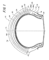
- a pneumatic tire 10 for a motorcycle of the present embodiment comprises a carcass 16 configured by a first carcass ply 12 and a second carcass ply 14 including cords extending in the intersecting direction with respect to a tire equatorial plane CL being buried.
- Both end portions of the first carcass ply 12 and the second carcass ply 14 are respectively wound up from the inner side to the outer side of the tire around a bead core 20 buried in a bead part 18.
- the first carcass ply 12 includes a plurality of cords (such as organic fiber cords made of nylon, for example) extending in the radial direction being buried with arrayed in parallel in coating rubber.
- the angles of the cords in the tire equatorial plane to the tire equatorial plane are set to 80 degrees.
- the second carcass ply 14 also includes a plurality of cords (such as organic fiber cords made of nylon, for example) extending in the radial direction being buried with arrayed in parallel in coating rubber.
- the angles of the cords in the tire equatorial plane to the tire equatorial plane are set to 80 degrees.
- the cord of the first carcass ply 12 and the cord of the second carcass ply 14 mutually intersect and incline in the mutually opposite directions to the tire equatorial plane CL.
- the end portions of the carcass ply can be sandwiched by a pair or a plurality of pairs of bead cores for engagement and can be caused to come close or in contact to the inner side surface or the outer side surface of the bead core in the tire width direction for engagement.
- a main intersecting layer 26 is arranged in the outer side in the tire radial direction of this carcass 16.
- the main intersecting layer 26 is configured by a first belt ply 26A and a second belt ply 26B.
- the first belt ply 26A includes a plurality of cords (cords with diameter of 0.7 mm made by twisting aromatic polyamide fiber, in the present embodiment) being buried with arrayed in parallel in the coating rubber.
- the angles of the cords in the tire equatorial plane to the tire equatorial plane are set to 60 degrees.
- the second belt ply 26B also includes a plurality of cords (cords of diameter of 0.7 mm made by twisting aromatic polyamide fiber, in the present embodiment) being buried with arrayed in parallel in the coating rubber.
- the angles of the cords in the tire equatorial plane to the tire equatorial plane are set to 60 degrees.
- the cord of the first belt ply 26A and the cord of the second belt ply 26B mutually intersect and incline in the mutually opposite directions to the tire equatorial plane CL.
- the cord thread density in the first belt ply 26A and the second belt ply 26B in the present embodiment is respectively 25 cords/50 mm.
- the main intersecting layer 26 is provided on the outer side of the carcass 16 in the tire radial direction but the main intersecting layer 26 can occasionally be omitted.
- At least one spiral belt layer 22 is provided outside this main intersecting layer 26 in the tire radial direction.
- This spiral belt layer 22 is formed by spirally winding, for example, a longitudinally shaped rubber coated cord made of one cord being coated with unvulcanized coating rubber or a beltlike ply made of a plurality of cords being coated with unvulcanized coating rubber.
- the cord direction is substantially taken as the circumferential direction of the tire.
- the cords in the spiral belt layer 22 can be organic fiber cords and can be steel cords.
- the spiral belt layer 22 of the present embodiment is formed by spirally winding a band form including two cords (cords with diameter of 0.7 mm made by twisting aromatic polyamide fiber) being buried in parallel in the coating rubber in the rotary axis direction of the tire.
- the cord thread density in the spiral belt layer 25 in the present embodiment is 50 cords/50 mm.
- a cushion rubber layer 38, an inclination belt layer 24 as an auxiliary belt layer and a tread rubber 30 forming a tread 28 are arranged in order in the outer side in the tire radial direction of the spiral belt layer 22.
- the cushion rubber layer 38 is arranged across the entire region between the spiral belt layer 22 and the inclination belt layer 24.
- Rubber different from coating rubber of the spiral belt layer 22 and coating rubber of the inclination belt layer 24 is used for the cushion rubber layer 38.
- the same rubber as the tread rubber 30 can be used. But rubber with elastic modulus lower than that of the tread rubber 30 is preferably used.
- rubber having elastic modulus of 50% of the tread rubber 30 is used for the cushion rubber layer 38.
- the inclination belt layer 24 includes a plurality of cords (cords with diameter of 0.7 mm made by twisting aromatic polyamide fiber in the present embodiment) being buried with arrayed in parallel in the coating rubber.
- the cord of the inclination belt layer 24 is preferably set to 45 to 90 degrees to the circumferential direction of the tire and is set to 90 degrees for the present embodiment.
- the cord thread density in the inclination belt layer 24 of the present embodiment is 50 cords/50 mm.
- No groove is formed in the tread 28 illustrated in Figure 1 but a groove for drainage to be considered necessary during traveling on a wet road surface can be formed.
- the width TW of the tread 28 being measured along the tire surface is 240 mm and the width SW of the spiral belt layer 22 is 230 mm.
- the thickness of the cushion rubber layer 38 is 2.5 mm
- the thickness of the tread rubber 30 is 3.8 mm
- the thickness of the inclination belt layer 24 is 0.7 mm. Accordingly, total tread thickness from the outer periphery of the spiral belt layer to the tread surface is 7.0 mm.
- the radial tire 10 for a motorcycle of the present embodiment is provided with the spiral belt layer 22 on the outer side of the carcass 16 in the radial direction of the tire. Therefore, tension stiffness in the circumferential direction of the tread 28 gets intensive so that protrusion of the tread 28 to the outer side in the radial direction of the tire during rapid traveling can be suppressed to improve rapid durability.
- the cushion rubber layer 38 having elastic modulus lower than that of the tread rubber 30 is arranged on the spiral belt layer 22 and the inclination belt layer 24 including a cord inclining at an angle of 0 to 45 degrees to the circumferential direction of the tire is arranged on the cushion rubber layer 38. Therefore, shear deformation in the circumferential direction of the cushion rubber layer 38 during traveling can be transmitted to the tread rubber 30 after being smoothed by the inclination belt layer 24.
- shear deformation in the circumferential direction of the tread rubber layer 30 can be reduced relatively because shear deformation occurs in the cushion rubber layer 3 8 in place of the tread rubber 30, and since the slip component of the tread rubber 30 in the circumferential direction of the tire becomes more uniform in the ground contacting plane, partial abrasion can be suppressed in the present embodiment.
- the main intersecting layer 26 is arranged on the radially inner side of the tire of the spiral belt layer 22 and, therefore, inplane shear stiffness of the belt portion is intensified so that significant cannber thrust is obtainable.
- the main intersecting layer 26 is arranged on the radially inner side of the tire of the spiral belt layer 22, the main intersecting layer 26 is pushed by the spiral belt layer 22 to be hardly delaminated and thereby durability is improved.
- the cord of the inclination belt layer 24 is aromatic polyamide cords, antiplane bend stiffness in the tread portion increases only a little. Consequently, an effect of uniformity of slip characteristic is obtained with flexible ground contacting property being retained (without spoiling stable steering performance).
- the angle (to the circumferential direction of the tire) of the cord of the inclination belt layer 24 is less than 45 degrees, the inclination belt layer 24 hardly extends in the circumferential direction so that velocity difference of the belt due to difference in tire radius will be directly transmitted to the tread surface, which is not preferable.
- the cushion rubber layer 38 In addition, with thickness o the cushion rubber layer 38 being less than 0.5 mm, the cushion rubber layer 38 cannot be deformed sufficiently to enable no absorption of velocity difference. On the other hand, with thickness of the cushion rubber layer 38 exceeding 4.0 mm, the cushion rubber layer 38 can be deformed sufficiently to enable absorption of velocity difference. However, the cushion rubber layer 38 is too much deformed so that the cushion rubber layer 38 acts extremely softly to spoil stable performance of the tire when lateral force is applied to the tire. That is, the tire property lacking in a sense of stiffness is given rise to, which is not preferable.
- a pneumatic tire 10 for a motorcycle of the present embodiment is different from the first embodiment on the point that a main intersecting layer 26 is arranged between a spiral belt layer 22 and a cushion rubber layer 38 (that is, the positional relation between the spiral belt layer 22 and the main intersecting layer 26 is opposite to that of the first embodiment). Otherwise, the configuration is the same as that of the first embodiment.
- the spiral belt layer 22 By arranging the main intersecting layer 26 on the spiral belt layer 22, the spiral belt layer 22 the most hardly extending in the circumferential direction among belts can be brought apart from the tread surface so that shear deformation of the tread rubber 30 can be alleviated more.
- a third embodiment of a radial tire for a motorcycle of the present invention will be described with reference to Figure 2 .
- like reference numerals designate the same components as those of the first embodiment in the drawing to omit description thereon.
- a tread 28 becomes occasionally too much harder than antiplane bend stiffness in the case of arranging an inclination belt layer 24 across the entire tread region.
- flexible deformation of tire can be maintained by arranging the inclination belt layer 24 only on the both end sides of the tread but not arranging it in the tire center part.
- a cushion rubber layer 38 is arranged only between the inclination belt layer 24 and a spiral belt layer 22.
- the inclination belt layer 24 is preferably arranged at least within a range of 0.2 to 0.6L from the tread end to the tire equatorial plane CL side and not arranged closer to the tire equatorial plane CL side, that is, not closer to the equatorial plane by 0.6L.
- the tread center side is no longer allowed to get soft so as to fail in enhancing comfortable ride performance against vertical vibration during straight traveling.
- a fourth embodiment of a radial tire for a motorcycle of the present invention will be described with reference to Figure 3 .
- like reference numerals designate the same components as those of the first embodiment in the drawing to omit description thereon.
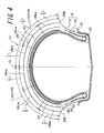
- a cushion rubber layer 38 and an inclination belt layer 24 are arranged in order in the radially outer side of a spiral belt layer 22.
- thickness of the cushion rubber layer 38 is partially different.
- Ds>Dc Ds being average thickness from the spiral belt layer 22 to the inclination belt layer 24 in a shoulder side region 28sa being close to the tread end 28E among trisected regions when the tread surface from the tire equatorial plane CL to the tread end 28E is equally divided into three portions; and Dc being average thickness from the spiral belt layer 22 to the inclination belt layer 24 in the center side region 28ca on the tire equatorial plane CL side among trisected regions.
- average thickness Ds of the cushion rubber layer in the shoulder side region 28sa is preferably set to within a range of 0.5 to 4.0 mm.
- Thickness Dc of the cushion rubber layer 38 in the center side region 28ca is preferably set to not less than 0.1 mm and less than 0.5 mm.
- thickness of the cushion rubber layer 38 is preferably changed gradually.
- the average thickness from the spiral belt layer 22 to the inclination belt layer 24 as an auxiliary belt layer is larger than that in the center side region 28ca. Therefore, shear deformation of the tread rubber 30 can be alleviated while suppressing the amount of rubber use.
- the cushion rubber layer 38 in the shoulder side region 28sa is less than 0.5 mm, the cushion rubber layer 38 cannot be deformed sufficiently to become unable to absorb velocity difference.
- the cushion rubber layer 38 in the shoulder side region 28sa exceed 4.0 mm, the cushion rubber layer 38 can be deformed sufficiently to enable absorption of velocity difference.
- the cushion rubber layer 38 is too much deformed so that the cushion rubber layer 38 acts extremely softly to spoil stable performance of the tire when lateral force is applied to the tire. That is, behavior become similar to that of the tire with too thick tread rubber to give rise to tire property lacking in a sense of stiffness, which is not preferable.
- thickness of the cushion rubber layer 38 can be less than 0.5 mm. Thereby, the weight of the pneumatic tire 10 for a motorcycle can be reduced.
- the lower limit value of thickness of the cushion rubber layer 38 in the center side region 28ca is 0.1 mm.
- a reason thereof is that direct contact between cords is meant in the case of 0 mm and there is a concern that the cords mutually friction at each tire deformation to bring destruction and, therefore, thickness of at least 0.1 mm is required.
- the cushion rubber layer 38 and the inclination belt layer 24 are arranged in order in the outer side in the radial direction of the spiral belt layer 22.
- the main intersecting layer 26 can be arranged between the spiral belt layer 22 and the cushion rubber layer 38.
- the cushion rubber layer 38 can be the same kind of rubber as the rubber coating the inclination belt layer 24. In that case, in the manufacturing process of tire, coating rubber in the inclination belt layer 24 is made thick so that the cord arrangement position in the interior inclination belt layer 24 is biased to enable preparation of the auxiliary belt layer 24 and the cushion rubber layer 38 as one sheet member so that efficiency at manufacturing can be increased.
- one kind of tire of the conventional example and five kinds of tire of embodiments to which the present invention is applied are prepared and steering performance comparing tests are carried out with an actual vehicle.
- An object of the tests relates to the point whether abrasion due to slip at traction is improved and the point whether the present invention results in any decrease in steering stability.
- only the rear tire is exchanged while the conventional front tire is always fixed.
- the tests are carried out by mounting a test tire on the rear wheel of a 1000 cc motorcycle of a sport type to carry out rather aggressive traveling with an actual vehicle (close to the limit) on a testing track. On one tire, traveling of ten rounds on the testing track is carried out (for approximately 25 minutes) to investigate the abrasion amount of the tire after traveling. For the abrasion amount, abrasion depth at the site where maximum abrasion occurred in the tread is measured. Strictly, the tire after finishing traveling is cut to measure thickness of the remaining tread rubber and the level of abrasion is measured based on the thickness that is originally present. This circuit is a clockwise circuit and there are a lot of right corners.
- the position undergoing maximum abrasion is near the shoulder of the tread on the right side of the tires for all the tires.
- stable steering performance is assessed simultaneously and comprehensively in the ten-point method based on feeling of a test rider.
- assessment comments of the test rider are also appended to show the results.
- the size of the test tire is 190/R50Z17.
- Tread thickness from the spiral belt layer to the tread surface is 7.0 mm.
- Thickness of cushion rubber layer is 2.5 mm. Thickness of tread rubber is 3.8 mm.
- Rubber of cushion rubber layer is same as tread rubber.
- Positional relation of the main intersecting layer and the spiral belt layer is opposite to that of the example 1.
- the inclination belt layer had width of 5.0 mm and was arranged immediately below the tread end.
- the cushion rubber layer (with 50 mm width) was arranged only on the inner side in the radial direction of the inclination belt layer.
- the elastic modulus of the cushion rubber layer is the same as embodiments, that is, 50% of tread rubber.
- the angle of cords in the inclination belt layer was 90 degrees.
- Abrasion amounts of all tires of the present invention of the examples 1 to 5 were less than that of the tire of the conventional example. That is, reduction in slip (slip in the circumferential direction) was confirmed. The particularly small abrasion amount was attained with the example 3. It is examined that distance from the spiral belt layer to the tread surface is the longest to provide structure enabling the most uniform slip in the circumferential direction.
- the softer cushion rubber layer provides the less abrasion amount.
- a result hereof is examined that smaller elastic modulus of the cushion rubber layer enables more absorption of velocity difference component in the circumferential direction of the belt and can make slip distribution uniform.
- hardness of the tires appears a little in the example 1 and the example 2.
- the reason hereof is deemed that the cushion rubber layer and the inclination belt layer as the auxiliary belt layer are arranged across the entire width of the tread and, therefore, antiplane bend stiffness in the tread portion is increased.
- the tire of the example 4 in which no cushion rubber layer and no inclination belt layer are present in the center portion does not provide improved traction during straight traveling, that is, traction with the ground contacting center portion.
- the structure of the present invention (the example 1) is considered to suppress slip also in the center part and to improve traction performance as a result of suppressing slip.
- the angle (the circumferential direction standard) of the cords in the inclination belt layer as the auxiliary belt layer is more preferably 90 degrees.
- the angles of the cords are set to 60 degrees and, therefore, the auxiliary belt layer is hardly extendable more than those of the example 4 in the circumferential direction. Consequently, effects of the present invention becomes less effective but increased the abrasion amount.
- any tire of the examples to which the present invention is applied provid significant improvement in abrasion resisting performance as compared with the conventional tire. This is an effect provided by distributing uniform shear force inside the tread to suppress local slip. In addition, since slip is suppressed, the grip force is increased so that improvement in stable steering performance is confirmed.
- one kind of tire of the conventional example and four kinds of tire of embodiments to which the present invention is applied are prepared and steering performance comparing tests are carried out with an actual vehicle.
- An object of the tests relates to the point whether abrasion due to slip at traction is improved and the point whether the present invention results in any decrease in steering stability.
- only the rear tire is exchanged while the conventional front tire is always fixed.
- the tests are carried out by mounting a test tire on the rear wheel of a 1000 cc motorcycle of a sport type to carry out rather aggressive traveling with an actual vehicle (close to the limit) on a testing track. On one tire, traveling of ten rounds on the testing track is carried out (for approximately 15 minutes) to investigate the abrasion amount of the tire after traveling. For the abrasion amount, abrasion depth at the site where maximum abrasion occurred in the tread is measured. Strictly, the tire after finishing traveling is cut to measure thickness of the remaining tread rubber and the level of abrasion is measured based on the thickness that is originally present. This circuit is a clockwise circuit and there are a lot of right corners.
- the position undergoing maximum abrasion is near the shoulder of the tread on the right side of the tires for all the tires.
- stable steering performance is assessed simultaneously and comprehensively in the ten-point method based on feeling of a test rider.
- assessment comments of the test rider are also appended to show the results.
- average lap time is also shown.
- the size of the test tire is 190/R50Z17.
- Structure Structure in exception of the cushion rubber layer and the inclination belt layer from the tire illustrated in Figure 3 and includes only a spiral belt layer as the reinforcing layer outside the carcass. Tread thickness from the spiral belt layer to the tread surface is 6.0 mm.
- Figure 3 Average thickness of the cushion rubber layer in the center side region is 1.0 mm. Average thickness of the cushion rubber layer in the shoulder side region is 3.0 mm. Thickness of the tread is 6.0 mm.
- Figure 3 Average thickness of the cushion rubber layer in the center side region is 0.2 mm. Average thickness of the cushion rubber layer in the shoulder side region is 3.0 mm. Thickness of the tread is 6.0 mm.
- Average thickness of the cushion rubber layer in the center side region is 3.0 mm.
- Average thickness of the cushion rubber layer in the shoulder side region is 3.0 mm (thickness of the cushion rubber layer cushion rubber layer is constant). Thickness of the tread is 6.0 mm.
- Figure 3 Average thickness of the cushion rubber layer in the center side region is 1.0 mm. Average thickness of the cushion rubber layer in the shoulder side region is 4.0 mm. Thickness of the tread is 6.0 mm.
- Figure 3 Average thickness of the cushion rubber layer in the center side region is 1.0 mm. Average thickness of the cushion rubber layer in the shoulder side region is 5.0 mm. Thickness of the tread is 6.0 mm.
- any of the examples 1 to 4 attain good stable steering performance without many abrasion amounts. That is, the cushion rubber layer and the inclination belt layer arranged thereon are apparently effective for reducing slip. As compared with the example 1 and the example 3, by making the cushion rubber layer thinner in the center side region than in the shoulder side region, the tire weight can be apparently made light to move the vehicle quickly. In addition, as in the example 2, by making thickness of the cushion rubber layer as thinner as possible to 0.2 mm in the center side region, the effect can be apparently increased further.
- any tire of the embodiment apparently balances improvement in abrasion resisting performance and improvement in stable steering performance at a high level. This is attained by making shear force distribution uniform in the tread and by the effect of suppressing local slip and the effect of making tire weight as light as possible.
Landscapes
- Engineering & Computer Science (AREA)
- Mechanical Engineering (AREA)
- Tires In General (AREA)
Abstract
Description
- The present invention relates to a pneumatic tire for a motorcycle, and in particular to a pneumatic tire for a motorcycle provided with abrasion resistance suitable to a motorcycle.
- A pneumatic tire for a motorcycle tends to expand in its diameter due to centrifugal force during rapid traveling and stability and durability during rapid traveling occasionally gets worse.
Therefore, in the recent years, as disclosed in the Patent Document 1 and the Patent Document 2, development of structure (so-called spiral structure) wound by steel and aromatic polyamide (KEVLAR: product name) in the circumferential direction of the tire progresses. Now tires with suppressed expansion of protrusion of the tire crown part during rapid traveling and enhanced stable performance during rapid traveling are supplied. - In addition, unlike the tire for passenger vehicles and trucks, the sectional plane of a tire crown part of the pneumatic tire for motorcycle looks like a round tire having smaller curvature radius than that of a tire for a four-wheeler due to the property of a motorcycle inclining its body to corner.
Therefore, in some ground contacting states, in the case where particularly large driving force works due to a position of the ground contacting part (a part brought into contact with the ground), slip distribution in the ground contacting plane becomes non-uniform so that the slip amount is likely to get different in particular in the center and the shoulder and partial abrasion causing rapid abrasion only in a portion is likely to occur.
This is confirmed as phenomena such as likeliness of rapid abrasion in an end part of a tread, for example, in the case of inclining the body significantly.
Patent Document 1:JP 2001-206009 A
Patent Document 2:JP 2002-316512 A - In general, in order to ensure the rapid durability and the rapid stable performance of a tire, a spiral reinforcing layer in which a cord extends in the circumferential direction of the tire is provided and a technique of preventing an increase of diameter due to centrifugal force during rapid traveling is adopted so that such a spiral reinforcing layer is buried in the position close to the radially outer side of the tire or the tread surface in a lot of cases.
However, such a spiral reinforcing layer suppresses extension in the circumferential direction of the tire strongly. Consequently, relative displacement between the spiral reinforcing layer and the tread surface occurs in the tread rubber to enlarge shear deformation in the circumferential direction. - In the case where the cannber angle is 0 degrees, that is, a tire is traveling straight, shear deformation of this tread rubber in the circumferential direction of the tire occurs to the traction direction in the center part of the ground contacting plane and occurs to the braking direction in the both end parts of the ground contacting shape in the width direction. The reason thereof is illustrated in
Figure 7 and is that, since atire 100 for a motorcycle is provided with a round crown shape, the perimeter of abelt 102 made of a spiral reinforcing layer of the center part of thetire 100 for motorcycle (D inFigure 7 ) in theground contacting plane 101 of the tire, that is, radius to the site where abelt 102 is arranged is different from that of the both end parts in the width direction (C inFigure 7 ). - In the case where the tire rotates at a constant velocity, the velocity of the
belt 102 is expressed by multiplying the radius of that portion and the angular velocity of the tire. However, since the belt radius is larger in the center part, the velocity of the center part is relatively faster. - However, since the tread surface is in contact to the road surface and any site travels at the same velocity during contact to the ground. As illustrated in
Figure 7 , in the case of the cannber angle being 0 degrees, the velocity of thebelt 102 of the tire center part D is faster than that of thetread surface 104. Therefore, thetread rubber 106 of the tire center part D accepts shear deformation to the traction direction and, on the other hand, the both end parts C of the ground contacting shape of thebelt 102 in the width direction are slower and, therefore, thetread rubber 106 of the both end parts C in the width direction accepts shear deformation to the braking direction. - In this state, in the case where driving force is applied to the
tire 100, the tire center part D already receiving shear deformation to the traction direction is likely to slip so that the tire center part D will start slipping in the case where large driving force is applied. - Next, in the case where the cannber is given so that the cannber angle is, for example, 45 degrees, that is, the case where a motorcycle is cornering will be described.
The sectional shape and the ground contacting shape of the tire are illustrated inFigure 6 .
In the case where thetire 100 contacts the ground at a cannber angle, shear deformation distribution in the circumferential direction in the ground contacting plane described above will become bilaterally asymmetrical. That is, the belt radius and the belt velocity of thetire 100 in A inFigure 6 near the center of the tread part is respectively larger and faster than those in the position B of the end part of the tread. - The traveling velocity of the tire (the tread surface contacts the road surface and moves together with the road surface and, therefore, this is considered to be velocity of the tread surface) is in the middle of the velocity of the
belt 102 in the position A and the velocity of thebelt 102 in the position B. Therefore, the position A enters the traction state where the belt is faster than the tread surface. The position B enters the braking state where the belt is slower than the tread surface. Such a phenomenon is likely to occur as difference between the belt radius in the A position and that in the B position gets larger. - That is, the tire of the motorcycle gets rounder as the crown shape of the
tire 100 comes nearer the end part so as to be likely to provide difference in the belt radius. Difference of shear deformation in the circumferential direction of thetread rubber 106 in the ground contacting plane is likely to get larger as the body is inclined more. - In addition, in the case where driving force is multiplied further in the ground contacting state at a cannber angle being 45 degrees, for example, shear deformation of the site of A to the traction direction in
Figure 6 is severer further since shear deformation to the traction direction has already occurred in the case where driving force is not multiplied and, therefore, thetread rubber 106 of the site of A reaches the slip limit first to start slipping. - When A starts slipping, the
tread rubber 106 in the site of B is originally provided with shear to the braking direction. Therefore, even when the driving force is applied, the shear state is not so large as that of thetread rubber 106 of A. Thus, even when A reaches the slip limit, the site of B does not reach the slip limit.
That is, a non-uniform state of slipping occurs in the ground contacting plane.
In general, abrasion of rubber occurs due to slip between the road surface and the tread rubber. Therefore, in the state as described above, only the site of A will gets abraded. - As described above, in the case of the tire provided with a spiral reinforcing layer, the reinforcing layer does not extend in the circumferential direction. Therefore, the velocity difference component of the belt due to tire radius will become apparently significantly influential.
In contrast, in the case of an intersecting belt layer lacking in the spiral reinforcing layer, the intersecting belt is deformed like pantograph so that the belt gets extendable or shrinkable in the circumferential direction so that the velocity difference component of the above described belt can be alleviated.
However, in the case of the spiral reinforcing layer, the velocity difference component directly appears to be slip difference on the tread surface. - The present invention is attained to solve the above described problems and an object is to provide a pneumatic tire for a motorcycle in which partial abrasion can be suppressed by making the slip component of a tread rubber in the circumferential direction of tire as uniform as possible in the ground contacting plane.
- In order to attain the above described objects, an aspect of the invention related to claim 1 is characterized by including a bead core buried in a left-right pair of bead part; a carcass made of not less than one sheet of carcass ply straddling in the troid state from one bead part to the other bead part with end portions being wound around the above described bead core or being sandwiched between bead cores or being arranged with the bead core and latched by the bead core; at least one sheet of spiral belt layer arranged outside this carcass in the tire radial direction with a band form including one or a plurality of cords arranged in parallel buried in coating rubber being wound spirally and formed; tread rubber arranged further outside the spiral belt layer in the tire radial direction to form a tread part contacting the road surface; not less than one auxiliary belt layer arranged between the spiral belt layer and the tread rubber with a plurality of cords being inclined at 45 to 90 degrees to the circumferential direction of the tire being buried in the coating rubber; and a cushion rubber layer arranged between the spiral belt layer and the auxiliary belt layer.
In the present invention, the cord used in the spiral belt layer can be a steel cord and can be an organic fiber cord made of aromatic polyamide, for example. - Next, an operation of the pneumatic tire for a motorcycle according to claim 1 will be described.
In the case where the spiral belt layer is positioned near the tread surface, shear deformation in the circumferential direction of the tread rubber is encouraged to become a cause of deteriorating partial abrasion as described above. That is, in the case where the belt layer being present inside the tread rubber is a spiral belt layer, the cord in the spiral belt layer does not extend in the circumferential direction and, therefore, shear deformation in the circumferential direction of the tread rubber is different in places, giving rise to a problem of non-uniformity.
However, the cushion rubber layer of the pneumatic tire for a motorcycle according to claim 1 can undergo shear deformation in the circumferential direction during traveling since the cushion rubber layer is arranged on the spiral belt layer.
And the auxiliary belt layer including a cord inclining at 45 to 90 degrees to the circumferential direction of the tire is arranged on the cushion rubber layer and, thereby, shear deformation of the cushion rubber layer can be transmitted to the tread rubber thereon after being smoothed by the auxiliary belt layer.
That is, as compared with a case not provided with the cushion rubber layer and the auxiliary belt layer, presence of the cushion rubber layer can reduce shear deformation of the tread rubber itself and can suppress partial abrasion since the cushion rubber layer instead of the tread rubber undergoes shear deformation (a portion of deformation of the tread rubber is taken over by the cushion rubber layer). - Here, the reason why the angle of the cord in the auxiliary belt layer is set to a range of 45 to 90 degrees to the circumferential direction of the tire is as follows.
Firstly, when the angle of the cord in the auxiliary belt layer is less than 45 degrees, the auxiliary belt layer is provided with tendency to be hardly expandable in the circumferential direction. Ultimately, with 0 degrees, this is not different from the spiral belt layer, in spite that the auxiliary belt layer is added, and the auxiliary belt layer does not extend in the circumferential direction as in the case of the spiral belt layer but the velocity difference of the belts will be directly transmitted to the tread surface. Therefore, at an angle with less than 45 degrees, extension hardly takes place the circumferential direction, which is not preferable. - On the other hand, in the case of 45 degrees or more, coating rubber between the cords of the member extends in the circumferential direction and thereby can extend as a member. In particular, in the case of 90 degrees, the cords are aligned in the width direction so that the rubber between the cords extends in the circumferential direction and therefore is preferably very likely to extend.
- In addition, the reason why not only the cushion rubber layer but also the auxiliary belt layer is necessary is as follows.
With only the cushion rubber layer, two rubber layers (the tread rubber and the cushion rubber layer) will be in the state of being stacked in the tire radial direction. In the case where this cushion rubber layer undergoes shear deformation, the tread rubber and the cushion rubber layer will undergo deformation with a bend for the lateral force in the tread width direction due to thickness of the rubber layers. - In contrast, the auxiliary belt layer with an angle of the cord being set to a range of 45 to 90 degrees to the circumferential direction of the tire is added between the tread rubber and the cushion rubber layer and then the spiral belt layer on the inner side of the cushion rubber layer and the auxiliary belt layer between the cushion rubber layer and the tread rubber establish parallel relation and, therefore, try to maintain that parallel relation even if deformation occurs. That is, as compared with the case only with the cushion rubber layer and the tread rubber, in the case of causing shear deformation, bend deformation of rubber hardly occurs under the operation of the auxiliary belt layer to give rise to a state which is stronger against shear deformation.
- In particular, taking, as an example, the case where the auxiliary belt layer is added to the tire equatorial plane at 90 degrees, the tread rubber gets stronger against force in the width direction than against force in the tire equatorial plane direction (the circumferential direction). That is, in such a case, shear deformation of traction and braking in the circumferential direction is likely to be absorbed so that the cushion rubber layer hardly undergoes shear deformation against cornering force from the lateral direction (cannber thrust).
- From such a point of view, unlike the case with only one set of the cushion rubber layer and the auxiliary belt layer, two or more sets of cushion rubber layer and auxiliary belt layer can be present as in the case with spiral belt layer + cushion rubber layer + auxiliary belt layer + another cushion rubber layer + another auxiliary belt layer + tread rubber.
- An aspect of the invention related to claim 2 is the pneumatic tire for a motorcycle according to claim 1 characterized in that a main intersecting layer comprising a plurality of belt plies with a plurality of second cords mutually arranged in parallel being buried in coating rubber, with mutually adjacent belt plies having the second cords being inclined for a tire equatorial plane in mutually opposite directions is arranged in the inner side in the tire radial direction of the spiral belt layer.
- Next, an operation of the pneumatic tire for a motorcycle according to claim 2 will be described.
The pneumatic tire for a motorcycle can include only the spiral belt layer for the belt portion. But a high-performance tire pursuing stable steering performance with only a spiral belt layer tends to get short in inplane shear stiffness of the belt portion. Therefore, large cannber thrust is hardly obtainable.
Therefore, in the case of pursuing more stable steering performance, two main intersecting layers in which cords mutually intersect with each other is arranged in combination with the spiral belt layer. That main intersecting layer is called a breaker. In general, the main intersecting layer, in which an organic fiber cord made of aromatic polyamide, for example, is struck, is used.
This pneumatic tire for a motorcycle is characterized in that the main intersecting layer is present on the inner side in the tire radial direction of the spiral belt layer. In the case where the main intersecting layer is present on the radially inner side of the spiral belt layer, the spiral belt layer pushes the main intersecting layer from outside so that the main intersecting layer gets hardly delaminated to improve durability. - An aspect of the invention related to
claim 3 is the pneumatic tire for a motorcycle according to claim 1 characterized in that a main intersecting layer comprising a plurality of belt plies with a plurality of second cords mutually arranged in parallel being buried in coating rubber, with mutually adjacent belt plies having the second cords being inclined for a tire equatorial plane in mutually opposite directions is arranged between the above described spiral belt layer and cushion rubber layer. - Next, an operation of the pneumatic tire for a motorcycle according to
claim 3 will be described.
The pneumatic tire for a motorcycle according toclaim 3 includes the main intersecting layer being arranged on the spiral belt layer in an attempt to arrange the spiral belt layer being the most hardly extendable in the circumferential direction in the position as far as from the tread surface. The point of this pneumatic tire is that a member being likely to extend is caused to come near the tread surface. - As described on the operation of the tire according to claim 1, the cord of the auxiliary belt layer being present in the most outer layer is inclined at 45 to 90 degrees to the circumferential direction of the tire. If this angle gets closer to 0 degree with respect to the circumferential direction of the tire, this belt layer starts functioning like a spiral belt layer so that shear deformation in the circumferential direction of the tread rubber will be encouraged. In the case where the angle is given in a range of 45 to 90 degrees to the circumferential direction of the tire, deformation occurring in the cushion rubber layer to become cushion material in its inside can be followed by extension in the circumferential direction. Also due to such a mechanism, the spiral belt layer is more preferable to be present inside the tire and the spiral belt layer is preferably present inside the main intersecting layer.
However, as in the case of the pneumatic tire for a motorcycle according to claim 2, even when the spiral belt layer is arranged outside the main intersecting layer, the cushion rubber layer thereon and, moreover, the auxiliary belt with the cord angle being 45 to 90 degrees to the circumferential direction of the tire sufficiently enable an improvement in performance. - Here, the pneumatic tire for a motorcycle according to
claim 3 includes the main intersecting layer being present outside the spiral belt layer and, moreover, the cushion rubber layer and the auxiliary belt are arranged thereon and, therefore, is more preferable against deformation of the tread rubber. - An aspect of the invention related to claim 4 is the pneumatic tire for a motorcycle according to any one of claim 1 to claim 3 characterized in that the cord in the above described auxiliary belt layer is an organic fiber cord.
- Next, an operation of the pneumatic tire for a motorcycle according to claim 4 will be described.
If the cord in the auxiliary belt layer is an organic fiber cord, an increase of antiplane bend rigidly in the tread portion of the tire is a little and, therefore, an effect of uniformity of slip characteristics of the present invention is obtainable with flexible ground contacting property being retained (without spoiling the stable steering performance). - An aspect of the invention related to claim 5 is the pneumatic tire for a motorcycle according to any one of claim 1 to claim 4 characterized in that thickness of the cushion rubber layer is set to within a range of 0.5 to 4.0 mm.
- Next, an operation of the pneumatic tire for a motorcycle according to claim 5 will be described.
Thickness of the cushion rubber layer will absorb belt velocity difference in the spiral belt layer (velocity difference is referred to, as described above, difference of belt velocity in the circumferential direction = rotary direction of the tire in the position in the direction of width of the tire).
With thickness of the cushion rubber layer being less than 0.5 mm, the cushion rubber layer cannot be deformed sufficiently to become unable to absorb velocity difference. On the other hand, with thickness of the cushion rubber layer exceeding 4.0 mm, the cushion rubber layer can be deformed sufficiently to enable absorption of velocity difference. However, the cushion rubber layer is too much deformed so that the cushion rubber layer acts extremely softly to spoil stable performance of the tire when lateral force is applied to the tire.
That is, if the cushion rubber layer is too thick, bend deformation occurs in the rubber to act substantially as the tire with too thick tread rubber giving rise to tire property lacking in a sense of stiffness, which is not preferable.
Here, thickness of the cushion rubber layer is preferably 0.7 to 3.5 mm and more preferably 1.0 to 3.0 mm. - An aspect of the invention related to claim 6 is the pneumatic tire for a motorcycle according to any one of claim 1 to claim 4, characterized by fulfilling Ds>Dc, Ds being average thickness from the spiral belt layer to the auxiliary belt layer in a shoulder side region being the closest to the tread end among trisected regions when the tread surface from the tire equatorial plane to the tread end is trisected; and Dc being average thickness from the spiral belt layer to the auxiliary belt layer in the center side region on the tire equatorial plane side among the trisected regions.
- Next, an operation of the pneumatic tire for a motorcycle according to claim 6 will be described.
This pneumatic tire for a motorcycle is provided with thicker average thickness from the spiral belt layer to the auxiliary belt layer in the shoulder side region than in the center side region of the tread. The reason hereof is that anteroposterior shear deformation of the tread rubber (driving near the center and braking near the shoulder) appears strongly in the shoulder side region of the tire so that average thickness for this portion from the spiral belt layer to the auxiliary belt layer is increased to alleviate the anteroposterior motion of tread. In the center side region of the tread, average thickness from the spiral belt layer to the auxiliary belt layer is made thin to suppress weight increase of the tire to the minimum.
In particular, in the case of a motorcycle, since the vehicle body is light, weight of tire significantly affects feeling of a rider on stable steering performance and lightness of a tire will be important since a human being and the vehicle body become one body to allow comfortable bike steering. - In claim 6, the tread surface from the tire equatorial plane to the tread end was equally divided into three portions. Thus, the reason of trisection is that the portion which contacts ground when the body is inclined significantly to make cannber angle at 45 or higher degrees is in the range of L/3 from the tread end, L being distance along the tread surface from the tread end to the tire equatorial plane. An average tire for motorcycle contacts a road surface only in the portion of approximately 1/6 of the entire tread width for cornering with the body being significantly inclined. That is, the shoulder side region represents the region contacting the ground in the tread when the tire is inclined like that.
In addition, the center side region is a region in contact to a road surface when the tire is traveling straight. - Here, as for the region between the shoulder side region and the center side region, thickness of the cushion rubber layer is not defined but is a changing zone since thickness varies from the center side region to the shoulder side region. Rapid change of thickness of the cushion rubber layer is not preferable since a step is generated on the tread surface. Thickness is preferably changed gradually and this change is preferably caused to occur in the region from the center side region to the shoulder side region.
- Here, thickness from the spiral belt layer to the auxiliary belt layer means a distance from the center of the cord configuring the spiral belt layer to the center of the cord configuring the auxiliary belt layer. In the case where two spiral belt layers are present, it will mean the distance from the center of the cord in the outermost spiral belt layer in the radial direction. In addition, in the case where two auxiliary belt layers are present, it will mean the distance to the center of the cord in the innermost auxiliary belt layer in the radial direction.
- Here, another belt layer being not the spiral belt layer (the cord is inclined at an angle being 40 or higher degrees to the tire equatorial plane) can be present outside in the radial direction of the spiral belt layer. Also for this case, there is no change in definition on thickness from the spiral belt layer to the auxiliary belt layer.
The reason hereof is that the belt layer including a cord being inclined at 40 or higher degrees to the tire equatorial plane besides the spiral belt layer can extend in the circumferential direction and, therefore, shear deformation can take place in the circumferential direction as in the case of the tread rubber even if this is positioned outside the spiral belt layer. - The reason why the average thickness is adopted from the spiral belt layer to the auxiliary belt layer in the center side region and the shoulder side region is that there is dispersion in thickness at the occasion of manufacturing a tire and, therefore, the actual condition making determination on thickness strictly in which position to be adopted difficult and the present invention substantially alleviate anteroposterior shear deformation distribution of the tread rubber at the time of cornering with the cannber angle at 45 or higher degrees to increase the lateral force to suppress anteroposterior slip to improve abrasion resistant property and, therefore, thickness had better to be defined on the tread region in its entirety contacting the ground at the cannber angle being 45 or higher degrees.
That is, average thickness in the tread site contacting the ground at the cannber angle being 45 degrees is preferably thick and should be average thickness in that region. - An aspect of the invention related to claim 7 is the pneumatic tire for a motorcycle according to claim 6, characterized in that thickness of the cushion rubber layer in the shoulder side region is set to within a range of 0.5 to 4.0 mm.
- Next, an operation of the pneumatic tire for a motorcycle according to claim 7 will be described.
Thickness of the cushion rubber layer will absorb belt velocity difference in the spiral belt layer (velocity difference is referred to, as described above, difference of belt velocity in the circumferential direction of the tire = rotary direction of the tire in the position in the direction of width of the tire). With thickness of the cushion rubber layer in the shoulder side region being less than 0.5 mm, the cushion rubber layer cannot be deformed sufficiently to be unable to absorb velocity difference. On the other hand, with thickness of the cushion rubber layer in the shoulder side region exceeding 4.0 mm, the cushion rubber layer can be deformed sufficiently to enable absorption of velocity difference. However, the cushion rubber layer is too much deformed so that the cushion rubber layer acts extremely softly to spoil stable property of the tire when lateral force is applied to the tire. That is, if the cushion rubber layer is too thick, deformation occurs in the cushion rubber layer to act substantially as the tire with too thick tread rubber giving rise to tire property lacking in a sense of stiffness, which is not preferable. - In addition, in claim 7, thickness of the cushion rubber layer in the shoulder side region is specified and that in the center side region is not specified. The reason hereof is that anteroposterior (the circumferential direction) shear deformation is extremely significant on the shoulder side of the tread and it becomes very important to alleviate shear deformation in the circumferential direction on the shoulder side.
Here, as for thickness of the cushion rubber layer in the center side region, thickness of the cushion rubber layer in the center side region is less than 4 mm since thickness of the cushion rubber layer in the center side region is thinner than thickness of the cushion rubber layer in the shoulder side region. In the case where the tread in the center side region is too thick, tire weight becomes unreasonably heavy to spoil steering stability. - An aspect of the invention related to claim 8 is the pneumatic tire for a motorcycle according to claim 6 or claim 7, characterized in that thickness of the above described cushion rubber layer in the above described center side region is set to less than 0.5 mm.
- Next, an operation of the pneumatic tire for a motorcycle according to claim 8 will be described.
Since shear deformation in the circumferential direction hardly occurs in the center side region compared with the shoulder side region, the cushion rubber layer can be made thin. Accordingly, thickness of the cushion rubber layer in the center side region can be made less than 0.5 mm and, thereby, tire weight can be made light. - An aspect of the invention related to claim 9 is the pneumatic tire for a motorcycle according to any one of claim 1 to claim 8, characterized in that elastic modulus of the above described cushion rubber layer is smaller than elastic modulus of the above described tread rubber.
- Next, an operation of the pneumatic tire for a motorcycle according to claim 9 will be described.
It is more convenient that the cushion rubber layer is softer since the cushion rubber layer functions to absorb velocity difference in the belt as described above. In particular, since two kinds of rubber on the belt, that is, the tread rubber and the cushion rubber layer are used, relative elastic modulus for the both parties becomes important in the case of considering shear deformation of the rubber part.
That is, if the cushion rubber layer is softer than the tread rubber, the cushion rubber layer in its inside can absorb the velocity difference component of the belt greatly.
On the contrary, if the cushion rubber layer is harder than the tread rubber, the cushion rubber layer cannot fully absorb the velocity difference component and therefore, the velocity difference component is likely to be transmitted to the tread rubber as well. - An aspect of the invention related to claim 10 is the pneumatic tire for a motorcycle according to any one of claim 1 to claim 9, characterized in that the auxiliary belt layer is arranged only on the both sides of the tread so as not to be arranged on the tread center side and the auxiliary belt layer is arranged within a range of 0.2 to 0.6L at least from the tread end to the tire equatorial plane side and is not arranged 0.6L closer to the tire equatorial plane side from the tread end to the tire equatorial plane side, L being the tread half width from the tire equatorial plane to the tread end obtained by measuring the tread part along the tread surface.
- Next, an operation of the pneumatic tire for a motorcycle according to claim 10 will be described.
In particular, the velocity difference component of tire is likely to occur when a cannber angle is given as described above and, therefore, only this case can be made effective. Since there is a concern that the tread part becomes too much harder than the antiplane bend stiffness in the case of arranging the auxiliary belt layer across the entire tread region, flexible deformation of tire is maintained by arranging the auxiliary belt layer only on the both end sides of the tread but not arranging it in the tire center part. Thereby, both comfortable ride performance and the effect of the present invention can be established at the same time. - In particular, the ground contacting state when the body is inclined significantly at the cannber angle being 40 or higher degrees, for example, is observed to note that the entire region of the ground contacting plane when the body is inclined significantly can be substantially covered so that the other portions not contacting the ground can be made soft if the auxiliary belt layer is arranged within the above described range. Here, if the auxiliary belt layer is arranged closer to the tire equatorial plane side beyond the above described range, it will become impossible to soften the tread center side and to improve comfortable ride performance.
- As described above, according to the pneumatic tire for a motorcycle of the present invention, the slip component of tread rubber in the circumferential direction of tire can be made as uniform as possible in the ground contacting plane to suppress partial abrasion, giving rise to an excellent effect.
-
-
Figure 1 is a sectional diagram taken along the rotary axis of a pneumatic tire for a motorcycle according to a first embodiment; -
Figure 2 is a sectional diagram taken along the rotary axis of a pneumatic tire for a motorcycle according to a third embodiment; -
Figure 3 is a sectional diagram taken along the rotary axis of a pneumatic tire for a motorcycle according to a fourth embodiment; -
Figure 4 is a sectional diagram taken along the rotary axis of a pneumatic tire for a motorcycle according to another embodiment (variation of the fourth embodiment); -
Figure 5 is a sectional diagram taken along the rotary axis of a pneumatic tire for a motorcycle according to a conventional embodiment; -
Figure 6 is a sectional diagram with a ground contacting shape diagram of a pneumatic tire for a motorcycle when the body is inclined; and -
Figure 7 is a sectional diagram with a ground contacting shape diagram of a pneumatic tire for a motorcycle when the body is not inclined (at a cannber angle being 0 degrees). -
- 10
- pneumatic tire for motorcycle
- 16
- carcass
- 18
- bead part
- 20
- bead core
- 22
- spiral belt layer
- 24
- inclination belt layer (auxiliary belt layer)
- 26
- main intersecting layer
- 28
- tread
- 30
- tread rubber
- 38
- cushion rubber layer
- A first embodiment of a pneumatic tire for a motorcycle of the present invention will be described with reference to
Figure 1 .
As illustrated inFigure 1 , apneumatic tire 10 for a motorcycle of the present embodiment comprises acarcass 16 configured by afirst carcass ply 12 and a second carcass ply 14 including cords extending in the intersecting direction with respect to a tire equatorial plane CL being buried. - Both end portions of the
first carcass ply 12 and the second carcass ply 14 are respectively wound up from the inner side to the outer side of the tire around abead core 20 buried in abead part 18.
Thefirst carcass ply 12 includes a plurality of cords (such as organic fiber cords made of nylon, for example) extending in the radial direction being buried with arrayed in parallel in coating rubber. For the present embodiment, the angles of the cords in the tire equatorial plane to the tire equatorial plane are set to 80 degrees. The second carcass ply 14 also includes a plurality of cords (such as organic fiber cords made of nylon, for example) extending in the radial direction being buried with arrayed in parallel in coating rubber. For the present embodiment, the angles of the cords in the tire equatorial plane to the tire equatorial plane are set to 80 degrees. Here, the cord of thefirst carcass ply 12 and the cord of the second carcass ply 14 mutually intersect and incline in the mutually opposite directions to the tire equatorial plane CL.
Here, although not illustrated in the drawing, the end portions of the carcass ply can be sandwiched by a pair or a plurality of pairs of bead cores for engagement and can be caused to come close or in contact to the inner side surface or the outer side surface of the bead core in the tire width direction for engagement. - A
main intersecting layer 26 is arranged in the outer side in the tire radial direction of thiscarcass 16.
Themain intersecting layer 26 is configured by a first belt ply 26A and a second belt ply 26B.
The first belt ply 26A includes a plurality of cords (cords with diameter of 0.7 mm made by twisting aromatic polyamide fiber, in the present embodiment) being buried with arrayed in parallel in the coating rubber. For the present embodiment, the angles of the cords in the tire equatorial plane to the tire equatorial plane are set to 60 degrees. The second belt ply 26B also includes a plurality of cords (cords of diameter of 0.7 mm made by twisting aromatic polyamide fiber, in the present embodiment) being buried with arrayed in parallel in the coating rubber. For the present embodiment, the angles of the cords in the tire equatorial plane to the tire equatorial plane are set to 60 degrees. - Here, the cord of the first belt ply 26A and the cord of the second belt ply 26B mutually intersect and incline in the mutually opposite directions to the tire equatorial plane CL. In addition, the cord thread density in the first belt ply 26A and the second belt ply 26B in the present embodiment is respectively 25 cords/50 mm.
Here, for the present embodiment, themain intersecting layer 26 is provided on the outer side of thecarcass 16 in the tire radial direction but themain intersecting layer 26 can occasionally be omitted. - At least one
spiral belt layer 22 is provided outside thismain intersecting layer 26 in the tire radial direction. Thisspiral belt layer 22 is formed by spirally winding, for example, a longitudinally shaped rubber coated cord made of one cord being coated with unvulcanized coating rubber or a beltlike ply made of a plurality of cords being coated with unvulcanized coating rubber. The cord direction is substantially taken as the circumferential direction of the tire. The cords in thespiral belt layer 22 can be organic fiber cords and can be steel cords. - The
spiral belt layer 22 of the present embodiment is formed by spirally winding a band form including two cords (cords with diameter of 0.7 mm made by twisting aromatic polyamide fiber) being buried in parallel in the coating rubber in the rotary axis direction of the tire. Here, the cord thread density in the spiral belt layer 25 in the present embodiment is 50 cords/50 mm. - A
cushion rubber layer 38, aninclination belt layer 24 as an auxiliary belt layer and atread rubber 30 forming atread 28 are arranged in order in the outer side in the tire radial direction of thespiral belt layer 22. Thecushion rubber layer 38 is arranged across the entire region between thespiral belt layer 22 and theinclination belt layer 24. - Rubber different from coating rubber of the
spiral belt layer 22 and coating rubber of theinclination belt layer 24 is used for thecushion rubber layer 38. As rubber configuring thecushion rubber layer 38, the same rubber as thetread rubber 30 can be used. But rubber with elastic modulus lower than that of thetread rubber 30 is preferably used. For the present embodiment, rubber having elastic modulus of 50% of thetread rubber 30 is used for thecushion rubber layer 38. - The
inclination belt layer 24 includes a plurality of cords (cords with diameter of 0.7 mm made by twisting aromatic polyamide fiber in the present embodiment) being buried with arrayed in parallel in the coating rubber. The cord of theinclination belt layer 24 is preferably set to 45 to 90 degrees to the circumferential direction of the tire and is set to 90 degrees for the present embodiment. Here, the cord thread density in theinclination belt layer 24 of the present embodiment is 50 cords/50 mm. - No groove is formed in the
tread 28 illustrated inFigure 1 but a groove for drainage to be considered necessary during traveling on a wet road surface can be formed. - Here, the width TW of the
tread 28 being measured along the tire surface is 240 mm and the width SW of thespiral belt layer 22 is 230 mm. In addition, the thickness of thecushion rubber layer 38 is 2.5 mm, the thickness of thetread rubber 30 is 3.8 mm and the thickness of theinclination belt layer 24 is 0.7 mm. Accordingly, total tread thickness from the outer periphery of the spiral belt layer to the tread surface is 7.0 mm. - The
radial tire 10 for a motorcycle of the present embodiment is provided with thespiral belt layer 22 on the outer side of thecarcass 16 in the radial direction of the tire. Therefore, tension stiffness in the circumferential direction of thetread 28 gets intensive so that protrusion of thetread 28 to the outer side in the radial direction of the tire during rapid traveling can be suppressed to improve rapid durability. - During straight traveling, since the
cushion rubber layer 38 with elastic modulus lower than that of thetread rubber 30 is provided, as compared with the case where all is thetread rubber 30, comfortable ride property and vibration absorption property during straight traveling are improved. In addition, since wide ground contacting width can be ensured, straight traveling property can be improved. - On the other hand, when a vehicle corners, since the
spiral belt layer 22 and theinclination belt layer 24 retain parallel relation, sufficient side force can be generated to improve cornering stability without generating bend deformation in the tread rubber and the cushion rubber layer for the force in the width direction. - Moreover, in the
pneumatic tire 10 for a motorcycle of the present embodiment, thecushion rubber layer 38 having elastic modulus lower than that of thetread rubber 30 is arranged on thespiral belt layer 22 and theinclination belt layer 24 including a cord inclining at an angle of 0 to 45 degrees to the circumferential direction of the tire is arranged on thecushion rubber layer 38. Therefore, shear deformation in the circumferential direction of thecushion rubber layer 38 during traveling can be transmitted to thetread rubber 30 after being smoothed by theinclination belt layer 24. - Accordingly, as compared with a case not provided with the
cushion rubber layer 38 and theinclination belt layer 24, shear deformation in the circumferential direction of thetread rubber layer 30 can be reduced relatively because shear deformation occurs in thecushion rubber layer 3 8 in place of thetread rubber 30, and since the slip component of thetread rubber 30 in the circumferential direction of the tire becomes more uniform in the ground contacting plane, partial abrasion can be suppressed in the present embodiment. - In addition, for the
pneumatic tire 10 for a motorcycle of the present embodiment, themain intersecting layer 26 is arranged on the radially inner side of the tire of thespiral belt layer 22 and, therefore, inplane shear stiffness of the belt portion is intensified so that significant cannber thrust is obtainable. - Since the
main intersecting layer 26 is arranged on the radially inner side of the tire of thespiral belt layer 22, themain intersecting layer 26 is pushed by thespiral belt layer 22 to be hardly delaminated and thereby durability is improved. - In addition, since the cord of the
inclination belt layer 24 is aromatic polyamide cords, antiplane bend stiffness in the tread portion increases only a little. Consequently, an effect of uniformity of slip characteristic is obtained with flexible ground contacting property being retained (without spoiling stable steering performance). - Here, when the angle (to the circumferential direction of the tire) of the cord of the
inclination belt layer 24 is less than 45 degrees, theinclination belt layer 24 hardly extends in the circumferential direction so that velocity difference of the belt due to difference in tire radius will be directly transmitted to the tread surface, which is not preferable. - In addition, with thickness o the
cushion rubber layer 38 being less than 0.5 mm, thecushion rubber layer 38 cannot be deformed sufficiently to enable no absorption of velocity difference. On the other hand, with thickness of thecushion rubber layer 38 exceeding 4.0 mm, thecushion rubber layer 38 can be deformed sufficiently to enable absorption of velocity difference. However, thecushion rubber layer 38 is too much deformed so that thecushion rubber layer 38 acts extremely softly to spoil stable performance of the tire when lateral force is applied to the tire. That is, the tire property lacking in a sense of stiffness is given rise to, which is not preferable. - Next, a second embodiment of radial tire for a motorcycle of the present invention will be described.
Although not illustrated in the drawing, apneumatic tire 10 for a motorcycle of the present embodiment is different from the first embodiment on the point that amain intersecting layer 26 is arranged between aspiral belt layer 22 and a cushion rubber layer 38 (that is, the positional relation between thespiral belt layer 22 and themain intersecting layer 26 is opposite to that of the first embodiment). Otherwise, the configuration is the same as that of the first embodiment. - By arranging the
main intersecting layer 26 on thespiral belt layer 22, thespiral belt layer 22 the most hardly extending in the circumferential direction among belts can be brought apart from the tread surface so that shear deformation of thetread rubber 30 can be alleviated more. - Next, a third embodiment of a radial tire for a motorcycle of the present invention will be described with reference to
Figure 2 . Here, like reference numerals designate the same components as those of the first embodiment in the drawing to omit description thereon.
Atread 28 becomes occasionally too much harder than antiplane bend stiffness in the case of arranging aninclination belt layer 24 across the entire tread region. However, in apneumatic tire 10 for a motorcycle of the present embodiment, flexible deformation of tire can be maintained by arranging theinclination belt layer 24 only on the both end sides of the tread but not arranging it in the tire center part. Thus both comfortable ride performance and the effect of the present invention can be established at the same time. Here, acushion rubber layer 38 is arranged only between theinclination belt layer 24 and aspiral belt layer 22. - Here, with tread half width being L (= 0.5 TW), the
inclination belt layer 24 is preferably arranged at least within a range of 0.2 to 0.6L from the tread end to the tire equatorial plane CL side and not arranged closer to the tire equatorial plane CL side, that is, not closer to the equatorial plane by 0.6L. When theinclination belt layer 24 is arranged closer to the tire equatorial plane CL side beyond the above described range, the tread center side is no longer allowed to get soft so as to fail in enhancing comfortable ride performance against vertical vibration during straight traveling. - Next, a fourth embodiment of a radial tire for a motorcycle of the present invention will be described with reference to
Figure 3 . Here, like reference numerals designate the same components as those of the first embodiment in the drawing to omit description thereon.
As illustrated inFigure 3 , in apneumatic tire 10 for a motorcycle of the present embodiment, acushion rubber layer 38 and aninclination belt layer 24 are arranged in order in the radially outer side of aspiral belt layer 22. However, thickness of thecushion rubber layer 38 is partially different. - Ds>Dc is fulfilled, Ds being average thickness from the
spiral belt layer 22 to theinclination belt layer 24 in a shoulder side region 28sa being close to thetread end 28E among trisected regions when the tread surface from the tire equatorial plane CL to thetread end 28E is equally divided into three portions; and Dc being average thickness from thespiral belt layer 22 to theinclination belt layer 24 in the center side region 28ca on the tire equatorial plane CL side among trisected regions. - Here, average thickness Ds of the cushion rubber layer in the shoulder side region 28sa is preferably set to within a range of 0.5 to 4.0 mm. Thickness Dc of the
cushion rubber layer 38 in the center side region 28ca is preferably set to not less than 0.1 mm and less than 0.5 mm. - Here, in the region 28ma between the shoulder side region 28sa and the center side region 28sa, thickness of the
cushion rubber layer 38 is preferably changed gradually. - In the
pneumatic tire 10 for a motorcycle of the present embodiment, in the shoulder side region 28sa where shear deformation in the circumferential direction becomes larger than in the center side region 28ca, the average thickness from thespiral belt layer 22 to theinclination belt layer 24 as an auxiliary belt layer is larger than that in the center side region 28ca. Therefore, shear deformation of thetread rubber 30 can be alleviated while suppressing the amount of rubber use. - Here, with thickness of the
cushion rubber layer 38 in the shoulder side region 28sa being less than 0.5 mm, thecushion rubber layer 38 cannot be deformed sufficiently to become unable to absorb velocity difference. On the other hand, with thickness of thecushion rubber layer 38 in the shoulder side region 28sa exceeding 4.0 mm, thecushion rubber layer 38 can be deformed sufficiently to enable absorption of velocity difference. However, thecushion rubber layer 38 is too much deformed so that thecushion rubber layer 38 acts extremely softly to spoil stable performance of the tire when lateral force is applied to the tire. That is, behavior become similar to that of the tire with too thick tread rubber to give rise to tire property lacking in a sense of stiffness, which is not preferable.
As compared with the shoulder side region 28sa, shear deformation in the circumferential direction hardly occurs in the center side region 28ca. Therefore, thickness of thecushion rubber layer 38 can be less than 0.5 mm. Thereby, the weight of thepneumatic tire 10 for a motorcycle can be reduced. - However, the lower limit value of thickness of the
cushion rubber layer 38 in the center side region 28ca is 0.1 mm. A reason thereof is that direct contact between cords is meant in the case of 0 mm and there is a concern that the cords mutually friction at each tire deformation to bring destruction and, therefore, thickness of at least 0.1 mm is required. - Here, in the present embodiment, the
cushion rubber layer 38 and theinclination belt layer 24 are arranged in order in the outer side in the radial direction of thespiral belt layer 22. However as illustrated inFigure 4 , themain intersecting layer 26 can be arranged between thespiral belt layer 22 and thecushion rubber layer 38.
In addition, thecushion rubber layer 38 can be the same kind of rubber as the rubber coating theinclination belt layer 24. In that case, in the manufacturing process of tire, coating rubber in theinclination belt layer 24 is made thick so that the cord arrangement position in the interiorinclination belt layer 24 is biased to enable preparation of theauxiliary belt layer 24 and thecushion rubber layer 38 as one sheet member so that efficiency at manufacturing can be increased. - In order to confirm performance improving effects of the present invention, one kind of tire of the conventional example and five kinds of tire of embodiments to which the present invention is applied are prepared and steering performance comparing tests are carried out with an actual vehicle. An object of the tests relates to the point whether abrasion due to slip at traction is improved and the point whether the present invention results in any decrease in steering stability. For the tests, only the rear tire is exchanged while the conventional front tire is always fixed.
- The tests are carried out by mounting a test tire on the rear wheel of a 1000 cc motorcycle of a sport type to carry out rather aggressive traveling with an actual vehicle (close to the limit) on a testing track. On one tire, traveling of ten rounds on the testing track is carried out (for approximately 25 minutes) to investigate the abrasion amount of the tire after traveling. For the abrasion amount, abrasion depth at the site where maximum abrasion occurred in the tread is measured. Strictly, the tire after finishing traveling is cut to measure thickness of the remaining tread rubber and the level of abrasion is measured based on the thickness that is originally present. This circuit is a clockwise circuit and there are a lot of right corners. Therefore, the position undergoing maximum abrasion is near the shoulder of the tread on the right side of the tires for all the tires. In addition, stable steering performance is assessed simultaneously and comprehensively in the ten-point method based on feeling of a test rider. In addition, assessment comments of the test rider are also appended to show the results. Here, the size of the test tire is 190/R50Z17.
- Structure:
Figure 5 . Tread thickness from the spiral belt layer to the tread surface is 7.0 mm. - Maximum abrasion amount: 2.1 mm
- Assessment score on stable steering: 5 points
- Comments of rider: Gradual abrasion is probably going on as repeating round. In the ninth round and the tenth round, grip force obviously dropped.
- Structure:
Figure 1 . Thickness of cushion rubber layer is 2.5 mm. Thickness of tread rubber is 3.8 mm. - Maximum abrasion amount: 1.2 mm
- Assessment score on stable steering: 9 points
- Comments of rider: Grip force was highly perceptible from the initial period. Assumingly, the tire slipped little to consequently provide good grip. The tire seemed to grip firmly against lateral force also during cornering. Gradual abrasion is probably going on as repeating round. But the drop percentage was extremely small. During the ten rounds, stable traveling was feasible. In addition, also during straight traveling, traction grip in the vertical direction was good. However, the tire seemed to be a little hard.
- Structure:
Figure 1 . Rubber of cushion rubber layer is same as tread rubber. - Maximum abrasion amount: 1.5 mm
- Assessment score on stable steering: 8 points
- Comments of rider: Likewise the example 1, grip force was obviously highly perceptible from the initial period as compared with the conventional example. Gradual abrasion is probably going on as repeating round. But the drop percentage was extremely small. During the ten rounds, stable traveling was feasible. In addition, also during straight traveling, traction grip in the vertical direction was good. However, the tire seemed to be further harder than the tire of the example 1.
- Structure: Positional relation of the main intersecting layer and the spiral belt layer is opposite to that of the example 1.
- Maximum abrasion amount: 1.0 mm
- Assessment score on stable steering: 9 points
- Comments of rider: Approximately the same assessment likewise the example 1. Grip being better than that in the example 1 seemed to be provided when driving force is applied to the tire.
- Structure:
Figure 2 . The inclination belt layer had width of 5.0 mm and was arranged immediately below the tread end. In addition, the cushion rubber layer (with 50 mm width) was arranged only on the inner side in the radial direction of the inclination belt layer. The elastic modulus of the cushion rubber layer is the same as embodiments, that is, 50% of tread rubber. The angle of cords in the inclination belt layer was 90 degrees. - Maximum abrasion amount: 1.2 mm
- Assessment score on stable steering: 9 points
- Comments of rider: Likewise the example 1, extremely good stable steering performance was obtained in contrast with the conventional example. Comments on stable steering performance are likewise those on the example 1. However, as compared with the example 1, hardness of the tire was not perceptible much but smooth ride was attained. With the hard tire, jumping occasionally took place on the road surface and some sites become hardly controllable. However, in the example 4, the tire provided flexible grip at all corners. However, as for traction during straight traveling, grip achievement as that in the example 1 was not perceptible. Taking the point that the tire was not hard but provided good ride and the point that traction during straight traveling was not different from the conventional example into consideration, the assessment score is 9 points likewise that for the example 1.
- Structure: Likewise the example 4 except that the angle of cords in the inclination belt layer was 60 degrees.
- Maximum abrasion amount: 1.6 mm
- Assessment score on stable steering: 8 points
- Comments of rider: approximately the same feeling as that in the example 1 was attained. However, the tire was a little likely to slip when the throttle was opened from the state where the body is inclined.
- Abrasion amounts of all tires of the present invention of the examples 1 to 5 were less than that of the tire of the conventional example. That is, reduction in slip (slip in the circumferential direction) was confirmed.
The particularly small abrasion amount was attained with the example 3. It is examined that distance from the spiral belt layer to the tread surface is the longest to provide structure enabling the most uniform slip in the circumferential direction. - Comparing the example 1 with the example 2, the softer cushion rubber layer provides the less abrasion amount. A result hereof is examined that smaller elastic modulus of the cushion rubber layer enables more absorption of velocity difference component in the circumferential direction of the belt and can make slip distribution uniform. In addition, hardness of the tires appears a little in the example 1 and the example 2. The reason hereof is deemed that the cushion rubber layer and the inclination belt layer as the auxiliary belt layer are arranged across the entire width of the tread and, therefore, antiplane bend stiffness in the tread portion is increased.
- Comparing the example 1 with the example 4, if the inclination belt layer is arranged only on the shoulder side, slip on the shoulder can be apparently suppressed without increasing antiplane bend stiffness in the tread portion. However, in contrast with the conventional example, the tire of the example 4 in which no cushion rubber layer and no inclination belt layer are present in the center portion does not provide improved traction during straight traveling, that is, traction with the ground contacting center portion. In other words, the structure of the present invention (the example 1) is considered to suppress slip also in the center part and to improve traction performance as a result of suppressing slip.
- As a result of comparing the example 4 with the example 5, it is apparent that the angle (the circumferential direction standard) of the cords in the inclination belt layer as the auxiliary belt layer is more preferably 90 degrees. In the example 5, the angles of the cords are set to 60 degrees and, therefore, the auxiliary belt layer is hardly extendable more than those of the example 4 in the circumferential direction. Consequently, effects of the present invention becomes less effective but increased the abrasion amount.
- Apparently, any tire of the examples to which the present invention is applied provid significant improvement in abrasion resisting performance as compared with the conventional tire. This is an effect provided by distributing uniform shear force inside the tread to suppress local slip. In addition, since slip is suppressed, the grip force is increased so that improvement in stable steering performance is confirmed.
- In order to confirm performance improving effects of the present invention, one kind of tire of the conventional example and four kinds of tire of embodiments to which the present invention is applied are prepared and steering performance comparing tests are carried out with an actual vehicle. An object of the tests relates to the point whether abrasion due to slip at traction is improved and the point whether the present invention results in any decrease in steering stability. For the tests, only the rear tire is exchanged while the conventional front tire is always fixed.
- The tests are carried out by mounting a test tire on the rear wheel of a 1000 cc motorcycle of a sport type to carry out rather aggressive traveling with an actual vehicle (close to the limit) on a testing track. On one tire, traveling of ten rounds on the testing track is carried out (for approximately 15 minutes) to investigate the abrasion amount of the tire after traveling. For the abrasion amount, abrasion depth at the site where maximum abrasion occurred in the tread is measured. Strictly, the tire after finishing traveling is cut to measure thickness of the remaining tread rubber and the level of abrasion is measured based on the thickness that is originally present. This circuit is a clockwise circuit and there are a lot of right corners. Therefore, the position undergoing maximum abrasion is near the shoulder of the tread on the right side of the tires for all the tires. In addition, stable steering performance is assessed simultaneously and comprehensively in the ten-point method based on feeling of a test rider. In addition, assessment comments of the test rider are also appended to show the results. Moreover, average lap time is also shown. Here, the size of the test tire is 190/R50Z17.
- Structure: Structure in exception of the cushion rubber layer and the inclination belt layer from the tire illustrated in
Figure 3 and includes only a spiral belt layer as the reinforcing layer outside the carcass. Tread thickness from the spiral belt layer to the tread surface is 6.0 mm. - Tire weight: 6.2 kg
- Maximum abrasion amount: 2.1 mm
- Lap time average: 1 minute 41.3 seconds
- Assessment score on stable steering: 5 points
- Comments of rider: Gradual abrasion in the shoulder is probably going on as repeating round. In the ninth round and the tenth round, grip force at the time of inclining the body obviously dropped. Occurrence of traction results in slip to idle the rear tire.
- Structure:
Figure 3 . Average thickness of the cushion rubber layer in the center side region is 1.0 mm. Average thickness of the cushion rubber layer in the shoulder side region is 3.0 mm. Thickness of the tread is 6.0 mm. - Tire weight: 7.7 kg
- Maximum abrasion amount: 1.0 mm
- Lap time average: 1 minute 35.3 seconds
- Assessment score on stable steering: 8 points
- Comments of rider: Grip force was highly perceptible from the initial period. Assumingly, the tire slipped little to consequently provide good grip. The tire seemed to grip firmly against lateral force also during cornering. Gradual abrasion is probably going on as repeating round, thereby dropping the grip force. But the drop percentage of grip was extremely small. During the ten rounds, stable traveling was feasible. In addition, also during straight traveling, traction grip in the vertical direction was good. However, assumingly due to heaviness, responsiveness is slightly bad.
- Structure:
Figure 3 . Average thickness of the cushion rubber layer in the center side region is 0.2 mm. Average thickness of the cushion rubber layer in the shoulder side region is 3.0 mm. Thickness of the tread is 6.0 mm. - Tire weight: 7.3 kg
- Maximum abrasion amount: 1.0 mm
- Lap time average: 1 minute 34.3 seconds
- Assessment score on stable steering: 9 points
- Comments of rider: In addition to likewise achievement of the example 1, handling is better than that of the example 1. The tire was felt light and responsiveness was better than that of the example 1. Therefore, the motorcycle could be inclined promptly.
- Structure: Average thickness of the cushion rubber layer in the center side region is 3.0 mm. Average thickness of the cushion rubber layer in the shoulder side region is 3.0 mm (thickness of the cushion rubber layer cushion rubber layer is constant). Thickness of the tread is 6.0 mm.
- Tire weight: 8.4 kg
- Maximum abrasion amount: 1.0 mm
- Lap time average: 1 minute 35.9 seconds
- Assessment score on stable steering: 7 points
- Comments of rider: In spite of likewise achievement of the example 1, tire was felt extremely heavy and responsiveness of the body was bad.
- Structure:
Figure 3 . Average thickness of the cushion rubber layer in the center side region is 1.0 mm. Average thickness of the cushion rubber layer in the shoulder side region is 4.0 mm. Thickness of the tread is 6.0 mm. - Tire weight: 8.0 kg
- Maximum abrasion amount: 0.8 mm
- Lap time average: 1 minute 36.2 seconds
- Assessment score on stable steering: 7 points
- Comments of rider: In spite of likewise achievement of the example 1, tire was felt heavy. In addition, when the body is inclined, a little lateral limpness is felt.
- Structure:
Figure 3 . Average thickness of the cushion rubber layer in the center side region is 1.0 mm. Average thickness of the cushion rubber layer in the shoulder side region is 5.0 mm. Thickness of the tread is 6.0 mm. - Maximum abrasion amount: 0.8 mm
- Lap time average: 1 minute 39.7 seconds
- Assessment score on stable steering: 5 points
- Comments of rider: When the body is inclined, a lateral limpness was felt and a sense of stability for the body was missing.
- As compared with the conventional example, any of the examples 1 to 4 attain good stable steering performance without many abrasion amounts. That is, the cushion rubber layer and the inclination belt layer arranged thereon are apparently effective for reducing slip.
As compared with the example 1 and the example 3, by making the cushion rubber layer thinner in the center side region than in the shoulder side region, the tire weight can be apparently made light to move the vehicle quickly. In addition, as in the example 2, by making thickness of the cushion rubber layer as thinner as possible to 0.2 mm in the center side region, the effect can be apparently increased further. - Moreover, based on comparison among the example 1, the example 3 and the example 5, too thick cushion rubber layer in the shoulder side region apparently results in spoiling stable steering performance.
Any tire of the embodiment apparently balances improvement in abrasion resisting performance and improvement in stable steering performance at a high level. This is attained by making shear force distribution uniform in the tread and by the effect of suppressing local slip and the effect of making tire weight as light as possible.
Claims (10)
- A pneumatic tire for a motorcycle comprising a bead core buried in a left-right pair of bead parts,
a carcass made of not less than one sheet of carcass ply straddling in the troid state from one bead part to the other bead part with end portions being latched by the bead core,
at least one sheet of spiral belt layer arranged outside the carcass in the tire radial direction with a band form including one or a plurality of cords arranged in parallel buried in coating rubber being wound spirally and formed,
tread rubber arranged further outside the spiral belt layer in the tire radial direction to form a tread part contacting the road surface,
not less than one auxiliary belt layer arranged between the spiral belt layer and the tread rubber with a plurality of cords being inclined at 45 to 90 degrees to the circumferential direction of the tire being buried in the coating rubber and
a cushion rubber layer arranged between the spiral belt layer and the auxiliary belt layer. - The pneumatic tire for a motorcycle according to claim 1, wherein a main intersecting layer comprising a plurality of belt plies with a plurality of second cords mutually arranged in parallel being buried in coating rubber, with mutually adjacent belt plies having the second cords being inclined for a tire equatorial plane in mutually opposite directions is arranged in the inner side in the tire radial direction of the spiral belt layer.
- The pneumatic tire for a motorcycle according to claim 1, wherein a main intersecting layer comprising a plurality of belt plies with a plurality of second cords mutually arranged in parallel being buried in coating rubber, with mutually adjacent belt plies having the second cords being inclined for a tire equatorial plane in mutually opposite directions is arranged between the spiral belt layer and cushion rubber layer.
- The pneumatic tire for a motorcycle according to any one of claims 1 to 3, wherein the cord in the auxiliary belt layer is an organic fiber cord.
- The pneumatic tire for a motorcycle according to any one of claims 1 to 4, wherein thickness of the cushion rubber layer is set to within a range of 0.5 to 4.0 mm.
- The pneumatic tire for a motorcycle according to any one of claims 1 to 4, wherein Ds>Dc is fulfilled, Ds being average thickness from the spiral belt layer to the auxiliary belt layer in a shoulder side region, which is the closest to the tread end among trisected regions when the tread surface from the tire equatorial plane to the tread end is trisected; and Dc being average thickness from the spiral belt layer to the auxiliary belt layer in a center side region, which is the closest to the tire equatorial plane among the trisected regions.
- The pneumatic tire for a motorcycle according to claim 6, wherein thickness of the cushion rubber layer in the shoulder side region is set to within a range of 0.5 to 4.0 mm.
- The pneumatic tire for a motorcycle according to claim 6 or 7, wherein thickness of the cushion rubber layer in the center side region is set to less than 0.5 mm.
- The pneumatic tire for a motorcycle according to any one of claims 1 to 8, wherein elastic modulus of the cushion rubber layer is smaller than elastic modulus of the tread rubber.
- The pneumatic tire for a motorcycle according to any one of claims 1 to 9, wherein
the auxiliary belt layer is arranged only on the both sides of the tread so as not to be arranged on the tread center side and
the auxiliary belt layer is arranged within a range of 0.2 to 0.6L at least from the tread end to the tire equatorial plane side and is not arranged 0.6L closer to the tire equatorial plane side from the tread end to the tire equatorial plane side, L being a tread half width from the tire equatorial plane to the tread end obtained by measuring the tread part along the tread surface.
Applications Claiming Priority (3)
| Application Number | Priority Date | Filing Date | Title |
|---|---|---|---|
| JP2005245006 | 2005-08-25 | ||
| JP2005363220 | 2005-12-16 | ||
| PCT/JP2006/316617 WO2007023902A1 (en) | 2005-08-25 | 2006-08-24 | Pneumatic tire for bicycle |
Publications (4)
| Publication Number | Publication Date |
|---|---|
| EP1918128A1 true EP1918128A1 (en) | 2008-05-07 |
| EP1918128A4 EP1918128A4 (en) | 2009-10-21 |
| EP1918128B1 EP1918128B1 (en) | 2011-05-25 |
| EP1918128B8 EP1918128B8 (en) | 2012-01-18 |
Family
ID=37771645
Family Applications (1)
| Application Number | Title | Priority Date | Filing Date |
|---|---|---|---|
| EP06796730A Not-in-force EP1918128B8 (en) | 2005-08-25 | 2006-08-24 | Pneumatic tire for motorcycle |
Country Status (5)
| Country | Link |
|---|---|
| US (1) | US8011404B2 (en) |
| EP (1) | EP1918128B8 (en) |
| JP (1) | JP4860621B2 (en) |
| CN (1) | CN101296806B (en) |
| WO (1) | WO2007023902A1 (en) |
Cited By (3)
| Publication number | Priority date | Publication date | Assignee | Title |
|---|---|---|---|---|
| WO2016015896A1 (en) * | 2014-07-30 | 2016-02-04 | Continental Reifen Deutschland Gmbh | Bicycle tyre |
| EP2982519B1 (en) * | 2013-04-02 | 2017-08-30 | Bridgestone Corporation | Pneumatic tire for two-wheeled vehicles |
| US12391074B2 (en) | 2020-07-24 | 2025-08-19 | Continental Reifen Deutschland Gmbh | Pneumatic tire for bicycle |
Families Citing this family (13)
| Publication number | Priority date | Publication date | Assignee | Title |
|---|---|---|---|---|
| JP5179803B2 (en) * | 2007-08-27 | 2013-04-10 | 株式会社ブリヂストン | Pneumatic tires for motorcycles |
| JP5009722B2 (en) * | 2007-08-27 | 2012-08-22 | 株式会社ブリヂストン | Pneumatic tires for motorcycles |
| JP2009096419A (en) * | 2007-10-19 | 2009-05-07 | Bridgestone Corp | Pneumatic tire for two-wheel vehicle |
| KR101107761B1 (en) * | 2009-11-30 | 2012-01-20 | 한국타이어 주식회사 | Carcass cord structure of tire |
| US9776456B2 (en) * | 2011-01-19 | 2017-10-03 | The Goodyear Tire & Rubber Company | Zoned tread for racing tires |
| JP5723412B2 (en) * | 2013-05-20 | 2015-05-27 | 住友ゴム工業株式会社 | Method for manufacturing motorcycle tire |
| JP6346813B2 (en) * | 2014-07-22 | 2018-06-20 | 住友ゴム工業株式会社 | Tires for motorcycles |
| JP6911496B2 (en) * | 2017-05-01 | 2021-07-28 | 住友ゴム工業株式会社 | Motorcycle tires |
| JP6861144B2 (en) * | 2017-12-13 | 2021-04-21 | 株式会社ブリヂストン | tire |
| JP7006437B2 (en) * | 2018-03-26 | 2022-01-24 | 住友ゴム工業株式会社 | tire |
| JP7568397B2 (en) * | 2019-12-19 | 2024-10-16 | 株式会社ブリヂストン | Tire and wheel assembly |
| CN111251786B (en) * | 2020-03-17 | 2022-05-13 | 中策橡胶集团股份有限公司 | Motorcycle or electric vehicle tyre with 0-degree variable winding density belt ply |
| JP7631865B2 (en) | 2021-02-15 | 2025-02-19 | 住友ゴム工業株式会社 | Motorcycle tires |
Family Cites Families (12)
| Publication number | Priority date | Publication date | Assignee | Title |
|---|---|---|---|---|
| JPS62143705A (en) | 1985-12-17 | 1987-06-27 | Sumitomo Rubber Ind Ltd | motorcycle tires |
| JPH03169717A (en) | 1989-11-30 | 1991-07-23 | Sumitomo Rubber Ind Ltd | Tire for motorcycle |
| JPH03169713A (en) | 1989-11-30 | 1991-07-23 | Sumitomo Rubber Ind Ltd | Tire for motorcycle |
| EP0518869B1 (en) * | 1991-01-07 | 1995-06-21 | COMPAGNIE GENERALE DES ETABLISSEMENTS MICHELIN-MICHELIN & CIE | Pneumatic tyre for motorbikes |
| JPH09286204A (en) | 1996-04-23 | 1997-11-04 | Bridgestone Corp | Radial tire for two-wheeled vehicle |
| JPH1058917A (en) | 1996-08-14 | 1998-03-03 | Bridgestone Corp | Pneumatic tires for motorcycles |
| JP2001039116A (en) | 1999-07-28 | 2001-02-13 | Bridgestone Corp | Pneumatic tires for motorcycles |
| JP2001206009A (en) | 2000-01-25 | 2001-07-31 | Bridgestone Corp | Pneumatic tire |
| JP2001253207A (en) * | 2000-03-09 | 2001-09-18 | Bridgestone Corp | Pneumatic tire |
| JP3793415B2 (en) * | 2000-12-08 | 2006-07-05 | 住友ゴム工業株式会社 | Radial tires for motorcycles |
| JP4677116B2 (en) * | 2001-04-23 | 2011-04-27 | 株式会社ブリヂストン | Radial tires for motorcycles |
| JP4137701B2 (en) | 2003-05-28 | 2008-08-20 | 住友ゴム工業株式会社 | Motorcycle tires |
-
2006
- 2006-08-24 JP JP2007532173A patent/JP4860621B2/en not_active Expired - Fee Related
- 2006-08-24 WO PCT/JP2006/316617 patent/WO2007023902A1/en not_active Ceased
- 2006-08-24 CN CN2006800399937A patent/CN101296806B/en not_active Expired - Fee Related
- 2006-08-24 EP EP06796730A patent/EP1918128B8/en not_active Not-in-force
- 2006-08-24 US US12/064,692 patent/US8011404B2/en not_active Expired - Fee Related
Non-Patent Citations (2)
| Title |
|---|
| No further relevant documents disclosed * |
| See also references of WO2007023902A1 * |
Cited By (4)
| Publication number | Priority date | Publication date | Assignee | Title |
|---|---|---|---|---|
| EP2982519B1 (en) * | 2013-04-02 | 2017-08-30 | Bridgestone Corporation | Pneumatic tire for two-wheeled vehicles |
| WO2016015896A1 (en) * | 2014-07-30 | 2016-02-04 | Continental Reifen Deutschland Gmbh | Bicycle tyre |
| US9962995B2 (en) | 2014-07-30 | 2018-05-08 | Continental Reifen Deutschland Gmbh | Bicycle tyre |
| US12391074B2 (en) | 2020-07-24 | 2025-08-19 | Continental Reifen Deutschland Gmbh | Pneumatic tire for bicycle |
Also Published As
| Publication number | Publication date |
|---|---|
| EP1918128B1 (en) | 2011-05-25 |
| EP1918128B8 (en) | 2012-01-18 |
| US20090159164A1 (en) | 2009-06-25 |
| WO2007023902A1 (en) | 2007-03-01 |
| CN101296806B (en) | 2010-12-08 |
| US8011404B2 (en) | 2011-09-06 |
| CN101296806A (en) | 2008-10-29 |
| EP1918128A4 (en) | 2009-10-21 |
| JPWO2007023902A1 (en) | 2009-02-26 |
| JP4860621B2 (en) | 2012-01-25 |
Similar Documents
| Publication | Publication Date | Title |
|---|---|---|
| JP5063304B2 (en) | Pneumatic tires for motorcycles | |
| US8011404B2 (en) | Pneumatic tire for motorcycle | |
| JP5327957B2 (en) | Pneumatic tires for motorcycles | |
| US8127813B2 (en) | Pneumatic tire for two-wheeled vehicle | |
| US8616256B2 (en) | Radial tire for motorcycle | |
| JP2010247744A (en) | Pneumatic tire for motorcycle | |
| JP2007131228A (en) | Pneumatic tire for two-wheel vehicle | |
| JP4325906B2 (en) | Pneumatic tires for motorcycles | |
| JP4976001B2 (en) | Pneumatic tires for motorcycles | |
| JP2010120436A (en) | Pneumatic tire for motorcycle | |
| WO2010119959A1 (en) | Pneumatic tire for two-wheeled motor vehicle | |
| JP2009113604A (en) | Pneumatic tire for motorcycle | |
| JP2010120437A (en) | Pneumatic tire for motorcycle | |
| JP2010126004A (en) | Motorcycle pneumatic tire | |
| JP2010126005A (en) | Motorcycle pneumatic tire | |
| CN101626906A (en) | Pneumatic tire for two-wheeled motor vehicle | |
| JP2008143347A (en) | Pneumatic tire | |
| JP2009113603A (en) | Pneumatic tire for motorcycle | |
| JP2009120002A (en) | Pneumatic tire for motorcycle | |
| WO2020129971A1 (en) | Tire | |
| JP2009051414A (en) | Pneumatic tire for two-wheeled vehicle | |
| JP2009051412A (en) | Pneumatic tire for two-wheeled vehicle | |
| JP4568547B2 (en) | Pneumatic run flat tire | |
| JP5455185B2 (en) | Pneumatic tires for motorcycles | |
| JP2007083815A (en) | Pneumatic tire for two-wheeler |
Legal Events
| Date | Code | Title | Description |
|---|---|---|---|
| PUAI | Public reference made under article 153(3) epc to a published international application that has entered the european phase |
Free format text: ORIGINAL CODE: 0009012 |
|
| 17P | Request for examination filed |
Effective date: 20080225 |
|
| AK | Designated contracting states |
Kind code of ref document: A1 Designated state(s): DE ES FR GB IT |
|
| DAX | Request for extension of the european patent (deleted) | ||
| RBV | Designated contracting states (corrected) |
Designated state(s): DE ES FR GB IT |
|
| A4 | Supplementary search report drawn up and despatched |
Effective date: 20090923 |
|
| 17Q | First examination report despatched |
Effective date: 20100127 |
|
| GRAP | Despatch of communication of intention to grant a patent |
Free format text: ORIGINAL CODE: EPIDOSNIGR1 |
|
| RIN1 | Information on inventor provided before grant (corrected) |
Inventor name: ISHIYAMA, MAKOTOC/O BRIDGESTONE CORPORATION Inventor name: KOIDE, MASAFUMIC/O BRIDGESTONE CORPORATION |
|
| GRAS | Grant fee paid |
Free format text: ORIGINAL CODE: EPIDOSNIGR3 |
|
| GRAA | (expected) grant |
Free format text: ORIGINAL CODE: 0009210 |
|
| AK | Designated contracting states |
Kind code of ref document: B1 Designated state(s): DE ES FR GB IT |
|
| REG | Reference to a national code |
Ref country code: GB Ref legal event code: FG4D |
|
| REG | Reference to a national code |
Ref country code: DE Ref legal event code: R096 Ref document number: 602006022199 Country of ref document: DE Effective date: 20110707 |
|
| RTI2 | Title (correction) |
Free format text: PNEUMATIC TIRE FOR MOTORCYCLE |
|
| REG | Reference to a national code |
Ref country code: ES Ref legal event code: FG2A Ref document number: 2365354 Country of ref document: ES Kind code of ref document: T3 Effective date: 20110930 |
|
| PLBE | No opposition filed within time limit |
Free format text: ORIGINAL CODE: 0009261 |
|
| STAA | Information on the status of an ep patent application or granted ep patent |
Free format text: STATUS: NO OPPOSITION FILED WITHIN TIME LIMIT |
|
| 26N | No opposition filed |
Effective date: 20120228 |
|
| REG | Reference to a national code |
Ref country code: DE Ref legal event code: R097 Ref document number: 602006022199 Country of ref document: DE Effective date: 20120228 |
|
| REG | Reference to a national code |
Ref country code: DE Ref legal event code: R082 Ref document number: 602006022199 Country of ref document: DE Representative=s name: MARKS & CLERK (LUXEMBOURG) LLP, LU |
|
| REG | Reference to a national code |
Ref country code: FR Ref legal event code: CA Effective date: 20140812 |
|
| REG | Reference to a national code |
Ref country code: DE Ref legal event code: R082 Ref document number: 602006022199 Country of ref document: DE Representative=s name: MARKS & CLERK (LUXEMBOURG) LLP, LU Effective date: 20140828 Ref country code: DE Ref legal event code: R081 Ref document number: 602006022199 Country of ref document: DE Owner name: BRIDGESTONE CORPORATION, JP Free format text: FORMER OWNER: BRIDGESTONE CORP., TOKIO/TOKYO, JP Effective date: 20140828 |
|
| REG | Reference to a national code |
Ref country code: FR Ref legal event code: PLFP Year of fee payment: 11 |
|
| REG | Reference to a national code |
Ref country code: FR Ref legal event code: PLFP Year of fee payment: 12 |
|
| REG | Reference to a national code |
Ref country code: FR Ref legal event code: PLFP Year of fee payment: 13 |
|
| PGFP | Annual fee paid to national office [announced via postgrant information from national office to epo] |
Ref country code: FR Payment date: 20190822 Year of fee payment: 14 Ref country code: ES Payment date: 20190924 Year of fee payment: 14 Ref country code: DE Payment date: 20190822 Year of fee payment: 14 Ref country code: IT Payment date: 20190829 Year of fee payment: 14 |
|
| PGFP | Annual fee paid to national office [announced via postgrant information from national office to epo] |
Ref country code: GB Payment date: 20190821 Year of fee payment: 14 |
|
| REG | Reference to a national code |
Ref country code: DE Ref legal event code: R119 Ref document number: 602006022199 Country of ref document: DE |
|
| GBPC | Gb: european patent ceased through non-payment of renewal fee |
Effective date: 20200824 |
|
| PG25 | Lapsed in a contracting state [announced via postgrant information from national office to epo] |
Ref country code: IT Free format text: LAPSE BECAUSE OF NON-PAYMENT OF DUE FEES Effective date: 20200824 Ref country code: FR Free format text: LAPSE BECAUSE OF NON-PAYMENT OF DUE FEES Effective date: 20200831 Ref country code: DE Free format text: LAPSE BECAUSE OF NON-PAYMENT OF DUE FEES Effective date: 20210302 |
|
| PG25 | Lapsed in a contracting state [announced via postgrant information from national office to epo] |
Ref country code: GB Free format text: LAPSE BECAUSE OF NON-PAYMENT OF DUE FEES Effective date: 20200824 |
|
| REG | Reference to a national code |
Ref country code: ES Ref legal event code: FD2A Effective date: 20220110 |
|
| PG25 | Lapsed in a contracting state [announced via postgrant information from national office to epo] |
Ref country code: ES Free format text: LAPSE BECAUSE OF NON-PAYMENT OF DUE FEES Effective date: 20200825 |