EP1917397B1 - Procede et dispositif d'enlevement destines au remplacement de couches intermediaires - Google Patents
Procede et dispositif d'enlevement destines au remplacement de couches intermediaires Download PDFInfo
- Publication number
- EP1917397B1 EP1917397B1 EP06777035A EP06777035A EP1917397B1 EP 1917397 B1 EP1917397 B1 EP 1917397B1 EP 06777035 A EP06777035 A EP 06777035A EP 06777035 A EP06777035 A EP 06777035A EP 1917397 B1 EP1917397 B1 EP 1917397B1
- Authority
- EP
- European Patent Office
- Prior art keywords
- clearing
- track
- clearing apparatus
- sleepers
- rail
- Prior art date
- Legal status (The legal status is an assumption and is not a legal conclusion. Google has not performed a legal analysis and makes no representation as to the accuracy of the status listed.)
- Active
Links
- 238000000034 method Methods 0.000 title claims abstract description 14
- 241001669679 Eleotris Species 0.000 claims abstract 5
- 238000013016 damping Methods 0.000 description 2
- 238000005096 rolling process Methods 0.000 description 2
- 238000010276 construction Methods 0.000 description 1
- 238000001514 detection method Methods 0.000 description 1
- 238000003780 insertion Methods 0.000 description 1
- 230000037431 insertion Effects 0.000 description 1
- 239000000463 material Substances 0.000 description 1
- 239000004033 plastic Substances 0.000 description 1
- 238000011144 upstream manufacturing Methods 0.000 description 1
- 238000003466 welding Methods 0.000 description 1
Images


Classifications
-
- E—FIXED CONSTRUCTIONS
- E01—CONSTRUCTION OF ROADS, RAILWAYS, OR BRIDGES
- E01B—PERMANENT WAY; PERMANENT-WAY TOOLS; MACHINES FOR MAKING RAILWAYS OF ALL KINDS
- E01B29/00—Laying, rebuilding, or taking-up tracks; Tools or machines therefor
- E01B29/32—Installing or removing track components, not covered by the preceding groups, e.g. sole-plates, rail anchors
Definitions
- the invention relates to a method for removing or replacing the intermediate layers between rail and threshold or threshold plate, wherein the rail is lifted by loosening the rail screws from the thresholds. Furthermore, the invention relates to a clearing device for clearing rail intermediate layers, which comprises a roving head in the advance direction and subsequently an elongated guide body and can extend over at least three thresholds and a feed drive is provided which is preferably used for the inventive method.
- the replacement of the intermediate layers between rail and threshold or threshold plate has been made largely sections and by hand.
- the intermediate layers are made of elastic or damping material such as rubber or plastic.
- the intermediate layers are used in particular for concrete sleepers, as they have a lower vibration damping, than the previously used wooden sleepers.
- the intermediate layers are subject to wear and must therefore be replaced at certain intervals.
- the US-A-5 435 251 describes a method in which intermediate layers between rail and threshold are inserted substantially automatically by means of a machine.
- the disclosed machine has a reaming head arranged in the advance direction and subsequently an elongated guide body and a feed drive. The disclosed machine can not move forward under the raised rail.
- the inventive method is primarily characterized in that a clearing device is moved between the sleepers or threshold plates and the lifted rail.
- the clearing device according to the invention is characterized in that the clearing head has from a common axis to the rear extending clearing fingers pointing downwards Räumhaken.
- a clearing device is also provided, which is characterized in that a feed tong is provided for the feed drive, which is guided by the rail and has jaws for two-sided grasping the clearing device under the rail.
- the reamer is preferably used in combination with a vehicle assembly having successively a screwing machine for loosening the rail screws, a tool trolley with a lifting device for lifting the loosened rails and subsequently a second screwing machine for screwing the rails.
- a vehicle assembly having successively a screwing machine for loosening the rail screws, a tool trolley with a lifting device for lifting the loosened rails and subsequently a second screwing machine for screwing the rails.
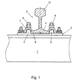
- Fig. 1 is a cross section through a rail of a track with lateral supervision on a threshold.
- Fig. 2 schematically shows from the side of a portion of a rail in the raised state with inserted clearing device.
- Fig. 3 shows the top view of the reamer in the position according to Fig. 2 .
- the Fig. 4a and 4b show a longitudinal section through the clearing head of the reamer in two different functional positions.
- Fig. 5 shows a detailed view of the lifting device for the rail and Fig. 6 the view of the feed tong for the reamer.
- Fig. 7 shows a side view of the feed drive.
- the Fig. 1 shows the structure of a rail fastening on a threshold 1.
- the threshold usually sits in a ballast bed, which is not shown here.
- the guide jaws 3, the foot 4 of the rail 5 are supported laterally.
- the rails screw 6 hold on spring clips 7, the rail firmly.
- the intermediate layer 8 is arranged for example rubber at each threshold.
- the rail fastening shown here is only one of many possibilities.
- the intermediate layer can also rest directly on the threshold. At the present The invention is always concerned with removing the intermediate layer 8 below the rail 5 and, if necessary, reloading it.
- the FIGS. 2 and 3 show the reamer 9 in side view and supervision.
- the reamer extends over at least 3 sleepers, so it always rests on 3 sleepers.
- the clearing device comprises a front clearing head 10 and subsequently an elongated guide body 11.
- the guide body 11 has two longitudinal struts 12 and a multiplicity of transverse struts 13.
- rollers or sliders 14 are arranged on each of the transverse struts 13 arranged.
- the rolling or sliding along the rail foot is particularly important where bumps such as welding burrs are to be overcome.
- Fig. 2 is the rail 5 in the lifted off in the direction of arrow 15 state, the lifting by the in Fig. 5 illustrated lifting device takes place. From this lifting device is in Fig. 2 only one of the rollers 16 shown, which engages under the rail head 17. The rail is about 3 cm from the thresholds 1 lifted so that the reamer 9 between the rail 4 and the thresholds 1 can be pulled through with a corresponding feed drive.
- the clearing head 10 comprises according to the Fig. 4a and 4b Clearance finger 18, which sit parallel to each other on a common axis 20 and extend from the clearing head to the rear.
- Each clearing finger has a downwardly facing Räumhaken 19.
- Fig. 4a was the clearing device pushed below the unillustrated rail foot on the intermediate layer 8 and the Räumhaken 19 summarize the intermediate layer 8.
- the Räumhaken 19 may be formed so that the Räumfinger dodge upward resilient when the Räumwiderstand is too large, for example, if the liner is missing and therefore strike the Räumhaken on the threshold or threshold plate.
- the Fig. 5 explains the lifting device for lifting the rail from the threshold.
- Such devices are known per se.
- the rail head 17 is engaged on both sides by the rollers of the roller tongs 21 and can be lifted by a hydraulic, not shown here, in the direction of the arrow 22.
- the roller tongs 21 in turn can be actuated by hydraulic cylinders 23 and is seated in a box-shaped support frame 24.
- the rail screws can be loosened continuously along a track, the rail can be raised and, after lowering, tightened again. In the off-hook condition, the reamer can do its job.
- a feed tong 25 is provided which comprises two jaws 26, which are each pivotable about an axis 27.
- the hydraulic cylinder 28 presses on both sides of the jaws 26 apart, whereby the reamer 9 is taken on both sides at the other end of the jaws.
- the ends of the jaws are preferably equipped with friction surfaces 29.
- the feed tong 25 is preferably guided by one or two guide rollers 30 on the rail 5. As a result, the ends of the jaws 26 are always in the correct position below the foot 4 of the rail.
- the Fig. 7 shows an embodiment of the feed drive for the feed gun 25.
- the feed gun 25 here has two successive guide rollers 30. However, it may also be sufficient to provide a single guide roller.
- the feed and return thrust for the feed gun 25 is provided by the hydraulic cylinder 31.
- This is hinged to a structural element 32 of the side wall of the vehicle, in particular a workshop car.
- the hydraulic ram is extended and the feed gun 25 detects the reamer 9.
- the hydraulic cylinder 31 pulls the feed gun 25 in the direction of arrow 33, taking with it the reamer 9. This clears the liner 8 from the threshold 1.
- the feed movement may in any case continue until the feed tong 25 may be at a threshold abuts. It depends on the rail fastening construction whether the feed tong 25 can be pulled continuously over the sleepers or whether a partial detection and release of the clearing device is necessary.
- the feed gun 25 is controlled so that before reaching the next threshold 1, the pliers release the reamer, is pulled over the threshold and attacked after passing the threshold again on the reamer.
Landscapes
- Engineering & Computer Science (AREA)
- Architecture (AREA)
- Civil Engineering (AREA)
- Structural Engineering (AREA)
- Machines For Laying And Maintaining Railways (AREA)
- Secondary Cells (AREA)
Claims (10)
- Procédé pour enlever ou remplacer des couches intermédiaires entre un rail et une traverse ou une plaque de traverse, le rail, après déboulonnage des boulons de rail, étant soulevé des traverses sur un tronçon de rail et rabaissé après le remplacement des couches intermédiaires et reboulonné, caractérisé en ce que l'on déplace entre le rail (5) et les traverses (1) un appareil (9) de déblaiement roulant ou glissant dans la dilection longitudinale du rail et enlevant les couches intermédiaires des traverses ou des plaques de traverse.
- Procédé suivant la revendication 1, caractérisé en ce que l'on déplace continuellement ou par à-coups l'appareil (9) de déblaiement dans la direction longitudinale du rail.
- Procédé suivant la revendication 1 ou 2, caractérisé en ce que l'on déplace l'appareil de déblaiement, lors du déblaiement des couches intermédiaires, exclusivement dans la partie en dessous des rails.
- Appareil de déblaiement pour déblayer des couches intermédiaires de rail, qui comprend une tête (10) de déblaiement se trouvant en avant dans le sens d'avance et venant ensuite un corps (11) de guidage s'étendant en longueur et qui peut s'étendre sur au moins trois traverses (1) et il prévu un entraînement d'avance, caractérisé en ce que la tête (10) de déblaiement comporte des doigts (18) de déblaiement s'étendant vers l'arrière à partir d'un axe (20) commun et ayant des crochets (19) de déblaiement tournés vers le bas.
- Appareil de déblaiement suivant la revendication 4, caractérisé en ce qu'il est prévu une pince (25) d'avance pour l'entraînement d'avance.
- Appareil de déblaiement suivant la revendication 5, caractérisé en ce que la pince (25) d'avance est guidée par le rail et a des mâchoires (26) de pince pour prendre des deux côtés l'appareil de déblaiement sous le patin du rail.
- Appareil de déblaiement pour le déblaiement de couches intermédiaires de rail, qui comprend une tête (10) de déblaiement se trouvant en avant dans le sens d'avance et venant ensuite un corps (11) de guidage s'étendant en longueur et qui peut s'étendre sur au moins trois traverses (1) et il prévu un entraînement d'avance, caractérisé en ce qu'il est prévu, pour l'entraînement d'avance, une pince (25) d'avance, qui est guidée par le rail et qui a des mâchoires (26) de pince, pour la prise des deux côtés de l'appareil de déblaiement sous le patin du rail.
- Appareil de déblaiement suivant la revendication 6 ou 7, caractérisé en ce que les mâchoires (26) de pince ont des surfaces de frottement.
- Appareil de déblaiement suivant l'une des revendications 4 à 8, caractérisé en ce que le corps de guidage comprend au moins deux longerons (12) et une pluralité de traverses (13), des galets de roulement ou des patins (14) étant disposés sur les traverses.
- Appareil de déblaiement suivant la revendication 9, caractérisé en ce que les galets de roulement ou les patins (14) sont disposés en saillie vers le bas et vers le haut en alternance sur les longerons (12).
Applications Claiming Priority (2)
| Application Number | Priority Date | Filing Date | Title |
|---|---|---|---|
| AT0140105A AT502439B1 (de) | 2005-08-25 | 2005-08-25 | Verfahren und räumgerät zum auswechseln von zwischenlagen |
| PCT/EP2006/008282 WO2007022966A1 (fr) | 2005-08-25 | 2006-08-23 | Procede et dispositif d'enlevement destines au remplacement de couches intermediaires |
Publications (2)
| Publication Number | Publication Date |
|---|---|
| EP1917397A1 EP1917397A1 (fr) | 2008-05-07 |
| EP1917397B1 true EP1917397B1 (fr) | 2010-10-27 |
Family
ID=37056595
Family Applications (1)
| Application Number | Title | Priority Date | Filing Date |
|---|---|---|---|
| EP06777035A Active EP1917397B1 (fr) | 2005-08-25 | 2006-08-23 | Procede et dispositif d'enlevement destines au remplacement de couches intermediaires |
Country Status (4)
| Country | Link |
|---|---|
| EP (1) | EP1917397B1 (fr) |
| AT (2) | AT502439B1 (fr) |
| DE (1) | DE502006008188D1 (fr) |
| WO (1) | WO2007022966A1 (fr) |
Family Cites Families (5)
| Publication number | Priority date | Publication date | Assignee | Title |
|---|---|---|---|---|
| AU3547978A (en) * | 1977-04-26 | 1979-11-01 | Morgan A R | Railway apparatus |
| AT358086B (de) * | 1977-05-06 | 1980-08-25 | Plasser Bahnbaumasch Franz | Einrichtung zum auswechseln der schienen- befestigungsmittel und gegebenenfalls der schienen eines gleises |
| US5435251A (en) * | 1993-12-03 | 1995-07-25 | Eastern Railway Supplies, Inc. | Applicator for applying chemically-impregnated pads to freshly-milled surfaces on railroad ties, and method of operating same |
| ATE250692T1 (de) * | 1998-09-09 | 2003-10-15 | Plasser Bahnbaumasch Franz | Maschine zur gleisbearbeitung |
| US6662729B1 (en) * | 2002-07-30 | 2003-12-16 | Harsco Technologies Corporation | Rail anchor spreader |
-
2005
- 2005-08-25 AT AT0140105A patent/AT502439B1/de not_active IP Right Cessation
-
2006
- 2006-08-23 AT AT06777035T patent/ATE486171T1/de active
- 2006-08-23 DE DE502006008188T patent/DE502006008188D1/de active Active
- 2006-08-23 EP EP06777035A patent/EP1917397B1/fr active Active
- 2006-08-23 WO PCT/EP2006/008282 patent/WO2007022966A1/fr not_active Ceased
Also Published As
| Publication number | Publication date |
|---|---|
| DE502006008188D1 (de) | 2010-12-09 |
| AT502439A1 (de) | 2007-03-15 |
| ATE486171T1 (de) | 2010-11-15 |
| AT502439B1 (de) | 2008-01-15 |
| WO2007022966A1 (fr) | 2007-03-01 |
| EP1917397A1 (fr) | 2008-05-07 |
Similar Documents
| Publication | Publication Date | Title |
|---|---|---|
| AT406276B (de) | Verfahren zur durchführung einer schwellenerneuerung | |
| AT402308B (de) | Stopfmaschine | |
| AT400341B (de) | Maschine zum schwellenwechseln | |
| DE3430291A1 (de) | Verfahren und maschine zum reinigen einer gleis-schotterbettung | |
| WO2015024626A1 (fr) | Procédé permettant le remplacement de traverses et le nettoyage de ballast sous une file de rails soulevée | |
| AT402307B (de) | Maschinenanordnung zum unterstopfen eines gleises | |
| DE3814732C2 (de) | Gleisverfahrbare Vorrichtung zum Räumen bzw. Planieren des Schotters eines Gleises mit Querschwellen | |
| AT413554B (de) | Stopfmaschine zum unterstopfen eines gleises | |
| AT500949A4 (de) | Maschine zur durchführung einer gleislagekorrektur | |
| AT508755A4 (de) | Stopfmaschine mit einer zusatzhebeeinrichtung | |
| EP1607523B1 (fr) | Machine pour le remplacement de traverses détériorées d'une voie ferrée. | |
| EP1917397B1 (fr) | Procede et dispositif d'enlevement destines au remplacement de couches intermediaires | |
| EP1443149A2 (fr) | Machine pour le traitement d'une voie | |
| EP1841919B1 (fr) | Procede pour nettoyer le ballast d'une voie ferree | |
| AT3876U2 (de) | Verfahren und maschine zur unterstopfung eines gleises | |
| DE2457272A1 (de) | Vorrichtung zur einstellung von schwellen eines eisenbahngleises rechtwinklig zu demselben (travelage) und zur ausrichtung derselben auf die gleisachse (equerrage) | |
| AT391501B (de) | Gleisstopfmaschine | |
| EP3411527A1 (fr) | Unité de soudage destinée au soudage des rails d'une voie | |
| AT391335B (de) | Gleisstopfmaschine | |
| DE4108993A1 (de) | Hilfshebevorrichtung fuer eisenbahnschienen | |
| AT518501B1 (de) | Schweißaggregat und Verfahren zum Verschweißen von Schienen eines Gleises | |
| AT502438B1 (de) | Verfahren und fahrzeugkombination zum bearbeiten von geleisen | |
| DE3814733C2 (de) | Gleisstopfmaschine | |
| AT520387A1 (de) | Verfahren und Vorrichtung zur Erneuerung von Schwellen eines Gleises | |
| DE102004005840B4 (de) | Vorrichtung zum Ausrichten von Schienen und deren Schwellen für Schienenanlagen von Kränen |
Legal Events
| Date | Code | Title | Description |
|---|---|---|---|
| PUAI | Public reference made under article 153(3) epc to a published international application that has entered the european phase |
Free format text: ORIGINAL CODE: 0009012 |
|
| 17P | Request for examination filed |
Effective date: 20080114 |
|
| AK | Designated contracting states |
Kind code of ref document: A1 Designated state(s): AT BE BG CH CY CZ DE DK EE ES FI FR GB GR HU IE IS IT LI LT LU LV MC NL PL PT RO SE SI SK TR |
|
| AX | Request for extension of the european patent |
Extension state: AL BA HR MK RS |
|
| 17Q | First examination report despatched |
Effective date: 20081202 |
|
| RAP1 | Party data changed (applicant data changed or rights of an application transferred) |
Owner name: OEBB-INFRASTRUKTUR AKTIENGESELLSCHAFT |
|
| GRAP | Despatch of communication of intention to grant a patent |
Free format text: ORIGINAL CODE: EPIDOSNIGR1 |
|
| GRAS | Grant fee paid |
Free format text: ORIGINAL CODE: EPIDOSNIGR3 |
|
| GRAA | (expected) grant |
Free format text: ORIGINAL CODE: 0009210 |
|
| AK | Designated contracting states |
Kind code of ref document: B1 Designated state(s): AT BE BG CH CY CZ DE DK EE ES FI FR GB GR HU IE IS IT LI LT LU LV MC NL PL PT RO SE SI SK TR |
|
| AX | Request for extension of the european patent |
Extension state: AL BA HR MK RS |
|
| REG | Reference to a national code |
Ref country code: GB Ref legal event code: FG4D Free format text: NOT ENGLISH |
|
| REG | Reference to a national code |
Ref country code: CH Ref legal event code: EP |
|
| REG | Reference to a national code |
Ref country code: IE Ref legal event code: FG4D Free format text: LANGUAGE OF EP DOCUMENT: GERMAN |
|
| REF | Corresponds to: |
Ref document number: 502006008188 Country of ref document: DE Date of ref document: 20101209 Kind code of ref document: P |
|
| REG | Reference to a national code |
Ref country code: NL Ref legal event code: VDEP Effective date: 20101027 |
|
| LTIE | Lt: invalidation of european patent or patent extension |
Effective date: 20101027 |
|
| PG25 | Lapsed in a contracting state [announced via postgrant information from national office to epo] |
Ref country code: LT Free format text: LAPSE BECAUSE OF FAILURE TO SUBMIT A TRANSLATION OF THE DESCRIPTION OR TO PAY THE FEE WITHIN THE PRESCRIBED TIME-LIMIT Effective date: 20101027 |
|
| REG | Reference to a national code |
Ref country code: IE Ref legal event code: FD4D |
|
| PG25 | Lapsed in a contracting state [announced via postgrant information from national office to epo] |
Ref country code: SE Free format text: LAPSE BECAUSE OF FAILURE TO SUBMIT A TRANSLATION OF THE DESCRIPTION OR TO PAY THE FEE WITHIN THE PRESCRIBED TIME-LIMIT Effective date: 20101027 Ref country code: FI Free format text: LAPSE BECAUSE OF FAILURE TO SUBMIT A TRANSLATION OF THE DESCRIPTION OR TO PAY THE FEE WITHIN THE PRESCRIBED TIME-LIMIT Effective date: 20101027 Ref country code: BG Free format text: LAPSE BECAUSE OF FAILURE TO SUBMIT A TRANSLATION OF THE DESCRIPTION OR TO PAY THE FEE WITHIN THE PRESCRIBED TIME-LIMIT Effective date: 20110127 Ref country code: LV Free format text: LAPSE BECAUSE OF FAILURE TO SUBMIT A TRANSLATION OF THE DESCRIPTION OR TO PAY THE FEE WITHIN THE PRESCRIBED TIME-LIMIT Effective date: 20101027 Ref country code: NL Free format text: LAPSE BECAUSE OF FAILURE TO SUBMIT A TRANSLATION OF THE DESCRIPTION OR TO PAY THE FEE WITHIN THE PRESCRIBED TIME-LIMIT Effective date: 20101027 Ref country code: SI Free format text: LAPSE BECAUSE OF FAILURE TO SUBMIT A TRANSLATION OF THE DESCRIPTION OR TO PAY THE FEE WITHIN THE PRESCRIBED TIME-LIMIT Effective date: 20101027 Ref country code: IS Free format text: LAPSE BECAUSE OF FAILURE TO SUBMIT A TRANSLATION OF THE DESCRIPTION OR TO PAY THE FEE WITHIN THE PRESCRIBED TIME-LIMIT Effective date: 20110227 Ref country code: PT Free format text: LAPSE BECAUSE OF FAILURE TO SUBMIT A TRANSLATION OF THE DESCRIPTION OR TO PAY THE FEE WITHIN THE PRESCRIBED TIME-LIMIT Effective date: 20110228 |
|
| PG25 | Lapsed in a contracting state [announced via postgrant information from national office to epo] |
Ref country code: GR Free format text: LAPSE BECAUSE OF FAILURE TO SUBMIT A TRANSLATION OF THE DESCRIPTION OR TO PAY THE FEE WITHIN THE PRESCRIBED TIME-LIMIT Effective date: 20110128 |
|
| PG25 | Lapsed in a contracting state [announced via postgrant information from national office to epo] |
Ref country code: ES Free format text: LAPSE BECAUSE OF FAILURE TO SUBMIT A TRANSLATION OF THE DESCRIPTION OR TO PAY THE FEE WITHIN THE PRESCRIBED TIME-LIMIT Effective date: 20110207 Ref country code: IE Free format text: LAPSE BECAUSE OF FAILURE TO SUBMIT A TRANSLATION OF THE DESCRIPTION OR TO PAY THE FEE WITHIN THE PRESCRIBED TIME-LIMIT Effective date: 20101027 Ref country code: CZ Free format text: LAPSE BECAUSE OF FAILURE TO SUBMIT A TRANSLATION OF THE DESCRIPTION OR TO PAY THE FEE WITHIN THE PRESCRIBED TIME-LIMIT Effective date: 20101027 Ref country code: EE Free format text: LAPSE BECAUSE OF FAILURE TO SUBMIT A TRANSLATION OF THE DESCRIPTION OR TO PAY THE FEE WITHIN THE PRESCRIBED TIME-LIMIT Effective date: 20101027 |
|
| PG25 | Lapsed in a contracting state [announced via postgrant information from national office to epo] |
Ref country code: DK Free format text: LAPSE BECAUSE OF FAILURE TO SUBMIT A TRANSLATION OF THE DESCRIPTION OR TO PAY THE FEE WITHIN THE PRESCRIBED TIME-LIMIT Effective date: 20101027 Ref country code: RO Free format text: LAPSE BECAUSE OF FAILURE TO SUBMIT A TRANSLATION OF THE DESCRIPTION OR TO PAY THE FEE WITHIN THE PRESCRIBED TIME-LIMIT Effective date: 20101027 Ref country code: PL Free format text: LAPSE BECAUSE OF FAILURE TO SUBMIT A TRANSLATION OF THE DESCRIPTION OR TO PAY THE FEE WITHIN THE PRESCRIBED TIME-LIMIT Effective date: 20101027 Ref country code: SK Free format text: LAPSE BECAUSE OF FAILURE TO SUBMIT A TRANSLATION OF THE DESCRIPTION OR TO PAY THE FEE WITHIN THE PRESCRIBED TIME-LIMIT Effective date: 20101027 |
|
| PLBE | No opposition filed within time limit |
Free format text: ORIGINAL CODE: 0009261 |
|
| STAA | Information on the status of an ep patent application or granted ep patent |
Free format text: STATUS: NO OPPOSITION FILED WITHIN TIME LIMIT |
|
| 26N | No opposition filed |
Effective date: 20110728 |
|
| REG | Reference to a national code |
Ref country code: DE Ref legal event code: R097 Ref document number: 502006008188 Country of ref document: DE Effective date: 20110728 |
|
| PG25 | Lapsed in a contracting state [announced via postgrant information from national office to epo] |
Ref country code: IT Free format text: LAPSE BECAUSE OF FAILURE TO SUBMIT A TRANSLATION OF THE DESCRIPTION OR TO PAY THE FEE WITHIN THE PRESCRIBED TIME-LIMIT Effective date: 20101027 |
|
| BERE | Be: lapsed |
Owner name: OBB-INFRASTRUKTUR A.G. Effective date: 20110831 |
|
| PG25 | Lapsed in a contracting state [announced via postgrant information from national office to epo] |
Ref country code: MC Free format text: LAPSE BECAUSE OF NON-PAYMENT OF DUE FEES Effective date: 20110831 |
|
| REG | Reference to a national code |
Ref country code: CH Ref legal event code: PL |
|
| GBPC | Gb: european patent ceased through non-payment of renewal fee |
Effective date: 20110823 |
|
| PG25 | Lapsed in a contracting state [announced via postgrant information from national office to epo] |
Ref country code: CH Free format text: LAPSE BECAUSE OF NON-PAYMENT OF DUE FEES Effective date: 20110831 Ref country code: LI Free format text: LAPSE BECAUSE OF NON-PAYMENT OF DUE FEES Effective date: 20110831 |
|
| REG | Reference to a national code |
Ref country code: FR Ref legal event code: ST Effective date: 20120430 |
|
| PG25 | Lapsed in a contracting state [announced via postgrant information from national office to epo] |
Ref country code: BE Free format text: LAPSE BECAUSE OF NON-PAYMENT OF DUE FEES Effective date: 20110831 |
|
| REG | Reference to a national code |
Ref country code: DE Ref legal event code: R119 Ref document number: 502006008188 Country of ref document: DE Effective date: 20120301 |
|
| PG25 | Lapsed in a contracting state [announced via postgrant information from national office to epo] |
Ref country code: GB Free format text: LAPSE BECAUSE OF NON-PAYMENT OF DUE FEES Effective date: 20110823 Ref country code: FR Free format text: LAPSE BECAUSE OF NON-PAYMENT OF DUE FEES Effective date: 20110831 |
|
| REG | Reference to a national code |
Ref country code: AT Ref legal event code: MM01 Ref document number: 486171 Country of ref document: AT Kind code of ref document: T Effective date: 20110823 |
|
| PG25 | Lapsed in a contracting state [announced via postgrant information from national office to epo] |
Ref country code: AT Free format text: LAPSE BECAUSE OF NON-PAYMENT OF DUE FEES Effective date: 20110823 |
|
| PG25 | Lapsed in a contracting state [announced via postgrant information from national office to epo] |
Ref country code: CY Free format text: LAPSE BECAUSE OF EXPIRATION OF PROTECTION Effective date: 20101027 Ref country code: LU Free format text: LAPSE BECAUSE OF NON-PAYMENT OF DUE FEES Effective date: 20110823 |
|
| PG25 | Lapsed in a contracting state [announced via postgrant information from national office to epo] |
Ref country code: DE Free format text: LAPSE BECAUSE OF NON-PAYMENT OF DUE FEES Effective date: 20120301 |
|
| PG25 | Lapsed in a contracting state [announced via postgrant information from national office to epo] |
Ref country code: TR Free format text: LAPSE BECAUSE OF FAILURE TO SUBMIT A TRANSLATION OF THE DESCRIPTION OR TO PAY THE FEE WITHIN THE PRESCRIBED TIME-LIMIT Effective date: 20101027 |
|
| PG25 | Lapsed in a contracting state [announced via postgrant information from national office to epo] |
Ref country code: HU Free format text: LAPSE BECAUSE OF FAILURE TO SUBMIT A TRANSLATION OF THE DESCRIPTION OR TO PAY THE FEE WITHIN THE PRESCRIBED TIME-LIMIT Effective date: 20101027 |