EP1914839A2 - Commutateur d'installation - Google Patents
Commutateur d'installation Download PDFInfo
- Publication number
- EP1914839A2 EP1914839A2 EP07019448A EP07019448A EP1914839A2 EP 1914839 A2 EP1914839 A2 EP 1914839A2 EP 07019448 A EP07019448 A EP 07019448A EP 07019448 A EP07019448 A EP 07019448A EP 1914839 A2 EP1914839 A2 EP 1914839A2
- Authority
- EP
- European Patent Office
- Prior art keywords
- terminal
- switching device
- connection
- clamping
- cover
- Prior art date
- Legal status (The legal status is an assumption and is not a legal conclusion. Google has not performed a legal analysis and makes no representation as to the accuracy of the status listed.)
- Granted
Links
- 238000009434 installation Methods 0.000 title claims description 39
- 239000004020 conductor Substances 0.000 claims description 91
- 125000006850 spacer group Chemical group 0.000 claims description 23
- 238000003780 insertion Methods 0.000 claims description 20
- 230000037431 insertion Effects 0.000 claims description 20
- IHQKEDIOMGYHEB-UHFFFAOYSA-M sodium dimethylarsinate Chemical class [Na+].C[As](C)([O-])=O IHQKEDIOMGYHEB-UHFFFAOYSA-M 0.000 claims description 16
- 239000000463 material Substances 0.000 claims description 10
- 238000005452 bending Methods 0.000 claims description 9
- 230000008878 coupling Effects 0.000 claims description 7
- 238000010168 coupling process Methods 0.000 claims description 7
- 238000005859 coupling reaction Methods 0.000 claims description 7
- 238000012360 testing method Methods 0.000 claims description 7
- 238000001746 injection moulding Methods 0.000 claims description 6
- 230000006835 compression Effects 0.000 claims description 2
- 238000007906 compression Methods 0.000 claims description 2
- 230000008901 benefit Effects 0.000 description 8
- 238000003825 pressing Methods 0.000 description 5
- 238000013461 design Methods 0.000 description 4
- 238000000034 method Methods 0.000 description 4
- 238000002347 injection Methods 0.000 description 3
- 239000007924 injection Substances 0.000 description 3
- 238000004519 manufacturing process Methods 0.000 description 3
- 230000007704 transition Effects 0.000 description 3
- 230000009471 action Effects 0.000 description 2
- 230000001154 acute effect Effects 0.000 description 2
- 230000000712 assembly Effects 0.000 description 2
- 238000000429 assembly Methods 0.000 description 2
- 230000005540 biological transmission Effects 0.000 description 2
- 230000008859 change Effects 0.000 description 2
- 238000010276 construction Methods 0.000 description 2
- 238000011161 development Methods 0.000 description 2
- 238000010292 electrical insulation Methods 0.000 description 2
- 230000007935 neutral effect Effects 0.000 description 2
- 230000008569 process Effects 0.000 description 2
- 230000000087 stabilizing effect Effects 0.000 description 2
- 239000013589 supplement Substances 0.000 description 2
- 238000009411 base construction Methods 0.000 description 1
- 238000005520 cutting process Methods 0.000 description 1
- 238000009826 distribution Methods 0.000 description 1
- 230000002349 favourable effect Effects 0.000 description 1
- 238000009413 insulation Methods 0.000 description 1
- 239000002075 main ingredient Substances 0.000 description 1
- 239000002991 molded plastic Substances 0.000 description 1
- 239000004033 plastic Substances 0.000 description 1
- 229920003023 plastic Polymers 0.000 description 1
- 239000000523 sample Substances 0.000 description 1
- 238000000926 separation method Methods 0.000 description 1
- 239000007779 soft material Substances 0.000 description 1
- 239000007787 solid Substances 0.000 description 1
- 210000002023 somite Anatomy 0.000 description 1
Images


Classifications
-
- H—ELECTRICITY
- H01—ELECTRIC ELEMENTS
- H01R—ELECTRICALLY-CONDUCTIVE CONNECTIONS; STRUCTURAL ASSOCIATIONS OF A PLURALITY OF MUTUALLY-INSULATED ELECTRICAL CONNECTING ELEMENTS; COUPLING DEVICES; CURRENT COLLECTORS
- H01R4/00—Electrically-conductive connections between two or more conductive members in direct contact, i.e. touching one another; Means for effecting or maintaining such contact; Electrically-conductive connections having two or more spaced connecting locations for conductors and using contact members penetrating insulation
- H01R4/28—Clamped connections, spring connections
- H01R4/48—Clamped connections, spring connections utilising a spring, clip, or other resilient member
- H01R4/4809—Clamped connections, spring connections utilising a spring, clip, or other resilient member using a leaf spring to bias the conductor toward the busbar
- H01R4/4828—Spring-activating arrangements mounted on or integrally formed with the spring housing
- H01R4/48365—Spring-activating arrangements mounted on or integrally formed with the spring housing with integral release means
Definitions
- the invention relates to an installation switching device with a housing and with two screwless terminal connections, each with at least one clamping spring for connecting connecting conductors, which is fixed in position in a terminal connection space of the housing, according to the preamble of claim 1.
- a generic installation switching device comprises within its housing at least one contact point with at least one fixed and one movable contact piece, via which a current leading from an input to an output terminal current path can be opened and closed.
- the contact point is generally operated by a rear derailleur with Verklinkungsstelle.
- a generic service switching device may further comprise tripping devices, for example a thermal release or a magnetic quick release, which act on the contact point or the rear derailleur when a short circuit or fault current occurs in the current path, so that the contact point is opened.
- screw-type terminal connections are used in addition to screw terminals in generic service switching devices.
- clamping elements can thereby plug terminals or spring terminals for Use come. In principle, these can greatly simplify the connection of connecting conductors, but today known installation switching devices with screwless terminal connections are subject to disadvantages.
- the EP 1 213 791 B1 shows an installation switching device with two superimposed and partially transversely shifted fasteners spring-type terminal. The actuation of the terminal element is only possible with an external tool.
- each terminal connection space to the housing sides and the front side open, and the two terminal connections are transverse to the broad side next to each other and in height above the mounting side against each other, and each of the two terminal terminals is covered by a terminal cover member pivotally connected to the housing.
- Each terminal cover part has a connection surface with a number of connection openings corresponding to the number of connection conductors to be connected, and guide means for the connection conductors formed on each connection opening.
- each terminal cover part has two side surfaces which, when attached Cover the terminal cover part of the terminal connection assigned to it laterally in the direction of the broad sides.
- spring actuation means are formed on the terminal cover and formed so that they act upon opening the cover against the clamping spring opening.
- the guide means are tube-like, an insertion channel forming hollow body, which also serve as a spring actuating means for the clamping spring.
- Each terminal connection of a service switching device comprises very few components, namely essentially only the clamping spring, a busbar with a clamping edge against which the clamping spring clamps the connecting conductor to be connected, and the terminal cover.
- An inventive installation switching device comprises two such terminal connections, which are arranged side by side on a connection side of the device. It is therefore very easy and inexpensive to manufacture.
- the two terminal connections are also offset in height above the mounting side against each other and thus offset. In this way, the creepage and clearance between the two terminal connections are lengthened, further securing the electrical insulation between the two terminal connections.
- An installation switching device has the overall advantage that two terminal connections are mounted on one connection side and in a terminal connection space in a simple manner and from the outside very convenient accessible side by side, the two terminal terminals are electrically isolated from each other and independently operable without tools. For insertion as well as removal of fixed and flexible terminal connection leads into or out of the terminal connection, no external tool is required.
- the terminal connections are easy to set up with just a few prefabricated components
- each terminal cover is resiliently acted upon by the associated clamping spring against the insertion direction of the external connection conductor and pressed against this clamping spring.
- the terminal cover part can be resiliently acted upon by the clamping spring assigned to it against a projection of the housing wall serving as a stop.
- the terminal cover is held by the resilient application of the associated clamping spring in a defined starting position. The starting position is the closed position of the clamping spring.
- the terminal cover can be made particularly simple and can be produced for example as a cost-effective injection molded part.
- the terminal cover part has an externally accessible, manually operable pressure surface.
- a further advantageous variant of the invention is characterized in that the terminal connection space between the two terminal connections comprises an insulating plate running parallel to the broad sides.
- the terminal connection space between the two terminal connections comprises an insulating plate running parallel to the broad sides.
- the terminal cover part can have a test opening for electrical contacting of the terminal connection.
- a further advantageous variant of the invention is characterized in that an adjustment opening is made in the vicinity of a terminal cover part in the housing wall. This makes it possible to intervene during manufacture or in the installed state of the finished mounted switching device with a tool inside the switching device to access an arranged there in the vicinity of the adjustment opening adjustment means.
- the terminal surface of the terminal cover with respect to the front of the housing and the guide means relative to the pad provides a possible embodiment of the invention that the terminal surface of the terminal cover is approximately parallel to the rear front side and the guide means are inclined relative to the terminal surface of the terminal cover.
- the angle of inclination for the guide means is selected, for example, according to the fact that the connection conductors remain easily accessible when mounting a service switching device according to the invention, for example in a distribution box, and the connection conductors are not bent too much towards the top.
- a further advantageous embodiment provides in this respect that the terminal surface of the terminal cover part inclined relative to the rear front side and the guide channels extend approximately perpendicular to the connection surface.
- the inclination angle at which the leads are inserted relative to the spring clip is determined in this embodiment by the angle of inclination of the guide channels.
- connection surface of the terminal cover opposite the rear front side, and the guide channels are inclined relative to the connection surface.
- the terminal cover having an engagement opening for an operating tool. Through this engagement opening can then be spent with the actuating tool, such as a screwdriver, the clamping spring in its open position.
- each terminal cover pivotally coupled a closure member which covers the terminal connection space on the front side in cooperation with a housing-fixed front end, wherein upon actuation of each terminal cover the closure member with the housing-side front end at least partially overlapped.
- the respective closure part and the housing-fixed part of the front side together form the front side.
- the respective closure part thus acts as a supplement to the housing-fixed part as klemmenabdeckteil workedes part of the front.
- the closure part is plate-shaped. It may advantageously be made in the same injection molding process as the terminal cover.
- a hinge for example a film hinge.
- a film hinge can be produced very inexpensively by injection molding.
- Another very advantageous embodiment of the invention is characterized in that the respective closure part is guided in each case displaceably parallel to the front side via laterally projecting guide pins in a housing-fixed, slide-like guide.
- the respective closure part is then overlapped and displaceably guided with the respectively associated housing-side part of the front side. It can be pivoted and moved when pressing the respective terminal cover behind the respective associated housing-side part of the rear front.
- a tight covering of the terminal receiving space is ensured to the front side with simultaneous movement of the terminal cover and mechanical stability of the rear front.
- a further very advantageous development of the invention is characterized in that the respective terminal cover part carries a spacer surface following the connection surface, which forms the terminal cover-side closure of the terminal receiving space in the region of the respective narrow side, the closure part being pivotably coupled to the end of the spacer surface facing the front side is.
- the spacer surface is designed to be stiff.
- a power transmission to the spring of the terminal is also possible by pressing the terminal cover over the spacer surface.
- the pressure surface of the terminal cover is due to the location of the terminal very close to the mounting side of the switching device in the installed position of the switching device, for example, in an installation distributor, by an operator is difficult to access.
- the distance surface can thus be used in a region which is not covered by a connecting conductor, as a second pressure surface for actuating the spring.
- the spacer surface carries an engagement opening for an actuating tool.
- the terminal can thus be operated via the terminal cover either manually or by means of a tool.
- the respective closure part is at least in the region of the coupling with the first part body of a material that has different mechanical properties than the first part body of the terminal cover.
- the closure part covers the terminal connection space on the front side in cooperation with a housing-fixed front side end, wherein upon actuation of the terminal cover part, the closure part at least partially overlaps the housing-fixed front side end.
- the respective closure part and the housing-fixed part of the front side together form the front side.
- the respective closure part thus acts as a supplement to the housing-fixed part as klemmenabdeckteil workedes part of the front.
- the hinge and the respective closure part in the region of the hinge consists of a material which has different mechanical properties than the first part body of the terminal cover part.
- the respective closure part at least in the region of the coupling with the first part body of the respective terminal cover part, consists of a material with different mechanical properties than the latter, the resilient properties of the respective closure part and its coupling to the respectively first part body can be independent of those of the respective first part Part body of the terminal cover part set and optimized for the intended use. This is particularly advantageous if other, sometimes even opposite, mechanical requirements are placed on the respective first part body of the terminal cover part than on the closure part.
- the first sub-body of the respective terminal cover has a high rigidity, so that the force can be transmitted to the opening of the respective clamping spring without deformation of the respective terminal cover.
- the respective closure part should be flexible, but at least flexibly coupled to the first part of the body of the terminal cover so that it can slide to save space during the pivoting of the terminal cover in the backdrop-like guides behind the housing-side front end.
- the closure part should be as parallel as possible to the housing-fixed front end.
- the angle between the first sub-body of the terminal cover and the housing-fixed front end changes during pivoting of the terminal cover. Therefore, a mobility of the closure part relative to the first part body of the terminal cover part is required at the coupling point, which can only be achieved by a flexibility of the material at this point.
- the spacer surface is designed stiff, and the closure part is at least in the region of the coupling with the spacer surface made of a soft material, which is softer than the spacer surface executed.
- a single component, the respective terminal cover has different material properties in some areas. Due to the rigid part of a transmission of force to the respective spring of the terminal is also possible by pressing the terminal cover over the spacer surface.
- the closure part, the second part can nevertheless turn easily and move parallel to the front panels and behind them.
- the terminal cover part is produced with the closure part coupled thereto in a two-component injection molding process.
- materials with different mechanical properties so for example hard and soft plastics, are joined together in injection molding.
- each terminal connection of an installation switching device comprises a compression spring acting on the conductor end clamping spring for clamping the conductor end to an abutment
- the clamping connection comprises a busbar with a terminal end and an adjoining discharge area.
- the busbar has a window-like recess with a supporting edge and a clamping edge opposite the supporting edge at the transition of the connection end into the diverting region.
- the clamping spring also has a support leg, with which it is supported on the support edge of the busbar. At the support leg includes a curved piece and a clamping leg, so that the conductor end between the clamping leg and the clamping edge is clamped as an abutment. The conductor end can be inserted from the side of the elbow piece into the window-like recess.
- the invention connects to the respective elbow a first part-clamping leg, which merges at a bending edge in a bent from the respective first part-clamping leg second part-clamping legs, so that the respective first and the second part-clamping legs a occupy obtuse angle with each other, the opening points in the insertion direction of the connecting conductor.
- the obtuse angle between the respective first and the respective second partial clamping legs offers the advantage that the point of application can be placed in the vicinity of the spring actuating means in the vicinity of the bending edges.
- the contact point of the spring actuating means may have a greater distance to the pivot point of the clamping leg on the elbow without the thereby achievable maximum terminal opening is smaller, and without the spring actuating means would be a connection conductor with a large cross section in the way.
- a greater distance between the contact point and the pivot point means a more favorable lever ratio and thus a lower actuation force for the user.
- a preferred embodiment is characterized in that the busbar has approximately a U-shape, wherein the terminal end forms the one U-leg, and the diverting region is formed by the transverse web and the other U-leg. It can be provided at the free end of the other U-leg upstand for attaching further conductors that lead into the interior of the service switching device.
- a discharge bar at the free end of the other U-leg and a discharge bar may be formed.
- the discharge bar can run approximately perpendicular to the other U-leg, and the side of the connection end opposite the clamping edge can be supported on the discharge bar.
- Another advantage of a service switching device is that the dissipation region of the busbar can be used for electrical contacting during the calibration of the bimetallic strip.
- the contact point for the calibration of the bimetallic strip is located at another location, outside the access area of the terminal connection, and is not accessible via the terminal connection. Since the calibration of the bimetallic strip can only take place in the fully assembled state, in the case of known service switching devices following the calibration, the separate access openings to the calibration contacts must be covered by additional cover parts.
- An inventive installation switching device can be completely assembled, except for the terminal cover parts. Now - by means of electrical contacting through the opening of the terminal terminal - the calibration of the bimetallic strip is made by the Ableit Scheme the busbar is used as a calibration contact. After calibration, the terminal cover is placed, and thus completed the installation switching device. A separate cover for the calibration opening is no longer required.
- the terminal connections of a service switching device according to the invention are designed so that they have only a small electrical resistance even with very narrow outer dimensions. This is achieved in that the bus bar in the discharge region between the clamping edge and the point at which another conductor is fixed, which leads into the interior of the service switching device, has a uniform width. This makes it possible to build installation switching devices according to the invention also in half standard module width.
- a division unit a is defined for the installation width of service switching devices.
- An installation switching device with a half standard module width thus has a mounting width of 9 mm.
- the busbar has only a single window-like recess for receiving a plurality of connection conductors.
- the individual connection conductors which are accommodated in the one recess of the busbar, are held apart by the connection openings and the guide means connected to them. For an individual insertion and removal of multiple connection conductors in only a single recess is possible without the individual connection conductors affect each other.
- the invention makes it possible to use two terminal connections next to one another in an installation switching device of a standard module width, which are electrically isolated from one another and do not have to overlap. As a result, electrical crosstalk between the two adjacent terminal connections is reliably avoided.
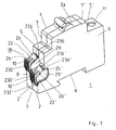
- FIGS. 1 to 5 An installation switchgear 1 according to the invention, see FIG. 1, has an insulating housing 3 formed from two housing parts 2, 2 'joined along a parting line 2a with a front front 4, rear front sides 5, 5', a fastening or connection side 6, front narrow sides 7, 7 ', which connect the front front side 4 with the rear front sides 5,5', rear narrow sides 8, 8 ', and two broad sides 9, of which in the view of Figure 1, only one is shown.
- a conventional screw terminal accessible by a terminal opening 11 for connecting connecting conductors is mounted in a terminal connection space provided inside the housing 3.
- a terminal connection space 18 is provided, which is open to the housing broad sides 9, to the rear narrow side 8 and to the rear front side 5.
- the terminal connection space 18 there are two terminal connections 10, 10 'which are transverse to the broad side 9 next to each other, and are shifted in height above the attachment side 6 against each other. Seen from the attachment side 6, therefore, a first terminal connection 10 lies above a second terminal connection 10 '.
- Each of the two terminal connections 10, 10 ' is fixed in position in the terminal connection space 18 and accessible for the connection of connection conductors 14 (see FIG. 3). Due to the openness of the terminal connection space on four sides, an increased flexibility for the connection direction of the connection conductor 14 is given.
- Each of the two terminal connections 10, 10 ' is covered by a terminal cover part 22, 22' assigned to it. This serves on the one hand to protect against contact of the current-carrying terminal connections, on the other hand - as will be shown below - it ensures a tool-free operation of the terminal connections.
- the cover of the terminal connection space 18 pointing towards the interior of the device is formed by a section 8a of the housing wall.
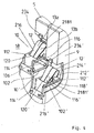
- the terminal cover 22, 22 ' has substantially the shape of a box open on two sides (see also Figure 2, in which as a section of Figure 1, only the upper terminal terminal 10 is shown). Two sides of this box are formed by two opposing cover plates on which laterally two side surfaces 29, 29 'are formed, which cover the terminal connection 10,10' laterally in the direction of broadsides 9 out.
- the first cover plate covers the associated terminal connection 10 or 10 'toward the rear front side 5 and has a connection surface 24 or 24', each with two connection openings 26 and 26 ', wherein a connection conductor can be connected through each of the connection openings 26, 26' ,
- the second cover plate covers the associated terminal connection 10 or 10 'toward the rear narrow side 8 and has an externally accessible, manually operable pressure surface 230 or 230'. At the free edge of the second cover plate has a semi-open, tubular cavity with which they are in one connected to the rear narrow side 8 of the housing 3 pivot pin 232 or 232 'is rotatably mounted.
- FIG. 1 shows an inventive installation switching device 1 with the terminal cover parts 22, 22 '
- FIG. 4 shows a view of the terminal connection space 18 with terminal cover parts removed.
- Each of the terminal connections 10 and 10 ' is a so-called plug-in terminal. Its construction will be described with reference to FIG. 3, which shows the terminal connection 10 from FIG. 2, but with the side face 29 of the terminal cover part 22 removed, and with reference to FIG. 4, in which the arrangement of the two terminal connections 10 and 10 'in the terminal connection compartment 18 is shown. be explained.
- the reference numerals without apostrophe refer to the upper terminal terminal 10, the reference numerals with apostrophe refer to the lower terminal terminal 10 '.
- the reference numerals without apostrophe are not mentioned because of the easier readability, however, drawn in the figures. Otherwise, the two terminal connections 10, 10 'are constructed essentially identically.
- the terminal connection 10 comprises a busbar 102 and a clamping spring 12.
- the terminal connection 10 rests on a projection formed in the interior of the housing 3, which is not shown in more detail here, and is there by way of webs and pins, of which only one pin is shown here by way of example 106 is fixed in position in a known manner in the terminal connection space 18.
- the busbar 102 includes a connection end 112 and a subsequent discharge region 114. At the connection end 112, it has a single window-like recess 116 with a support edge 118 and a clamping edge 120 opposite the support edge. The clamping edge 120 is located at the transition of the connection end 112 into the discharge region 114.
- the clamping spring 12 has a support leg 212, with which it is supported on the support edge of the bus bar 102.
- the support can be made so that the support leg 212 has at its free end a raised edge, with which it includes the supporting edge for the purpose of supporting partially.
- a curved piece 214 and thereon a clamping leg 216 connects.
- the conductor end 16 of a connecting conductor 14 is inserted from the side of the elbow 214 ago in the window-like recess 116 and is clamped between the clamping leg 216 and acting as an abutment clamping edge 120.
- the free end of the clamping leg 216 passes through the window-like recess 116th
- the clamping leg 216 of the clamping spring 12 is longitudinally slotted along a slot 218, so that two independently clampable part springs 13a, 13b arise with which two connection conductors can be clamped independently of each other.
- the busbar 102 has approximately a U-shaped basic shape, wherein the terminal end 112 forms the first U-leg, and the discharge region 114 is formed by a transverse web 220 and the second U-leg 222. At the free end of the second U-leg 222 a Aufkantung 224 is attached. At this Aufkantung 224 further connection conductors can be attached, with which the terminal connection 10 is connected to other modules within the switching device housing, such as the trigger assemblies. In particular, the connection conductors can be welded or brazed to this upstand, also a screwing or riveting is possible.
- An illustrated design of the busbar has the advantage that the forces acting on the terminal connection 10 when inserting and releasing the connecting conductor are absorbed by this as a closed system, and thus forces on other elements of the service switching device, such as the housing can be reduced.
- the busbar 102 can be produced cost-effectively and simply and in a wide variety of shapes, for example as a stamped and bent part in very large quantities.
- the terminal cover 22 By pressure on the pressure surface 230, the terminal cover 22 can be pivoted about the free edge of the second cover plate in the direction of the clamping spring 12 out. Falling out of the cover 22 is prevented by serving as a stop projection 234 on the housing wall.
- an insertion channel forming hollow body 28 are attached at the first cover plate of the cover member 22, aligned with the clamping spring 12, at each of the connection openings 26 tubular. These serve as a guide means for the introduced lead 14, and as spring actuation means.
- the cover member 22 is pivoted by pressure on the pressure surface 230 about the pivot pin 232 in the direction of the clamping spring 12, the hollow body 28 press the clamping leg 216 of the clamping spring 12 away from the clamping edge 120 of the bus bar 102, so that between the clamping edge 120th and the clamping leg 216 space for inserting the stripped terminal conductor end 16 of the connecting conductor 14 is formed.
- FIG. 3 shows this state.
- the clamping leg 216 of the clamping spring 12 presses the covering part 22 outward again due to its spring force via the hollow body 28 and at the same time clamps the end 16 of the connection conductor 14 against the clamping edge 120 the window-like recess 116.
- connection openings 26 are present in the connection surface 24 of the cover part 22, and behind each connection opening 26 is integrally formed on the connection surface a tubular hollow body 28 as a guide means for the connection conductor and spring action means (in the illustration of Figure 3 is only one of the hollow bodies 28 visible).
- Each connection opening 26 and each guide means 28 is one of the two partial clamping springs 13a, Assigned to 13 b, as they are caused by the slot 218 in the clamping spring 12. So if two conductors are to be clamped to a terminal connection, a conductor 14 is inserted through each of the two connection opening 26 and clamped by one of the partial clamping springs 13a, 13b.
- connection conductors 14 takes place in the hollow bodies 28 serving as guide means for the connecting conductors 14, thus no separate guiding or separating devices are required at the terminal connection. In particular, it is not necessary to divide the recess 116 into two receiving spaces by means of a web.
- the terminal connection 10 can be made very simple and narrow. In this way, two terminal connections can be installed side by side in an installation switching device with a standard module width, without the two terminal connections having to overlap. This is advantageous, for example, if one of the two terminal connections of one phase and the other, adjacent terminal connection is assigned to the neutral conductor. Then it is particularly important that no electrical connection between the two terminal connections can occur. If the terminal connections were not designed according to the invention, they would have to partially overlap in order to fit next to one another in an installation switchgear housing of a standard module width. As a result, there is a risk of electrical contact between the two terminal connections. The inventive arrangement of the two terminal connections a short circuit between the two terminal connections is reliably avoided even with adjacent terminal connections in a housing with a standard - module width.
- the cover member 22 is pressed in the state of rest to the outside against the projection 234, so that the cover always assumes a defined position in the idle state.
- the cover thus fulfills two functions: once the functions of the leadership of the connection conductor and the second, the function of the spring actuating tool. Without external actuating tool for the clamping spring, both rigid and flexible conductor ends can be clamped with the device according to the invention and also removed again from the terminal, namely at two terminal connections arranged next to one another.
- an additional slot could be present through which then an external tool for actuating the clamping spring 12 could be inserted therethrough.
- a test opening 236 is further attached. Through this test opening, the clamping spring 12 can be electrically contacted by means of a test probe.
- the terminal surface 24 of the cover 22 extends inclined to the rear front side 5.
- the guide means 28 are approximately perpendicular to the pad 24.
- the inclination angle at which the terminal conductor 14 is inserted into the terminal so determined by the inclination angle of the pad 24.
- An embodiment is also conceivable in which the connection surface 24 extends approximately parallel to the rear front side 5, and the guide means 28 are inclined with respect to the connection surface 24. Then, the inclination angle at which the leads 14 are inserted into the clamp is determined by the inclination angle of the guide means 28 opposite to the pad 24.
- the cover 22 can be made very cheap as an injection molded plastic part in an injection process.
- FIG. 5 shows a further embodiment of an installation switching device according to the invention, in which an insulating plate 244 extending parallel to the broad sides is inserted between the two terminal connections 10, 10 '.
- FIG. 6 shows a particular embodiment of such an insulating plate 244. This consists essentially of two parallel plates 247, 248, with different lengths, which are connected at a free end by a web 249, so that a total of a U-shape with two different length legs is formed.
- the insulating plate 244 is inserted between the two terminal connections 10 and 10 'so that the longer of the two plates 247 cover the upper terminal terminal 10 and the shorter of the two plates 248 cover the lower terminal terminal 10' toward the center of the service switching device.
- pins 250 are still attached to the plates 247, 248, with which the insulating plate 244 in corresponding grooves on the Inside the housing parts 2, 2 'engages and thereby immovably between the two terminal terminals 10,10' is held.
- an insulating plate 244 By using an insulating plate 244 according to FIG. 5, a contact and thus an electrical contact between the two terminal connections 10, 10 'are prevented even more reliably.
- the insulating plate acts mechanically stabilizing, for example, it prevents slippage of the terminal connections 10, 10 'transverse to the broad side 9 into the interior of the switching device into it.
- an adjustment opening 246 is introduced above the lower terminal connection 10 'in the section 8a of the housing wall. Through this can be intervened from the direction of the terminal connection space forth with a tool inside the switching device, for example, to access a nearby there in the adjustment hole 246 adjusting means, such as a setting screw to access.
- the embodiments shown illustrate the invention by way of example. Under no circumstances should they limit the invention to the embodiments shown there. Thus, it is also conceivable, for example, to place the two terminal connections without offset, that is to say in relation to the fastening side 6, at the same height next to one another.
- the specific embodiment of the terminal cover parts 22, 22 ' is also not limited to the box shape shown. In particular, the second cover plate could be longer than shown.
- the terminal connections 10,10 'could also be arranged at a different point on the rear narrow side 8, for example oriented even further in the direction of the fastening side 6.
- the invention has been explained above the example of a service switching device in shell construction, in which two housing shells are joined together along a parting line parallel to the broad sides.
- the invention can also be realized on a service switching device in base construction, in which the housing is assembled from two parts along a parting line parallel to the mounting side.
- FIGS. 7 and 8 are considered.
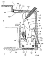
- FIG. 7 shows a partial sectional view of the terminal connection space 18 of another service switching device 1 according to the invention. Only the first, lower terminal connection 10 is shown. The second, upper terminal connection 10 'is designed accordingly, but with a shortened distance surface of its associated second terminal cover.
- the service switching device 1 has an insulating housing formed from two housing parts 2 with a front side 304, a rear front side 305, a mounting side 6, a front narrow side 7, a rear narrow side 8, and two broad sides 9, of which in the view of Figure 1 only one, lying in the drawing plane, is shown.
- the terminal connection space 18 is laterally, ie towards the broad side, limited by the housing broad sides 9 of the insulating housing 3.
- an opening 20 of the terminal connection space 18 is formed through a recess in the rear front side 305 of the housing part 2, through which the terminal connection 10 fixed in position in the terminal connection space 18 is accessible for the connection of connection conductors 14.
- a housing-side section 356 of the rear front side 305 connects.
- an opening 20 is formed on the rear front side 305 in the region between the end of the housing-side section 356 facing away from the front narrow sides 7 and the rear narrow side 8.
- the opening 20 of the terminal connection space 18 extends over the abutting edges between the rear narrow side 8 and the rear front side 305 away still in the rear narrow side 8 inside. This has the advantage that increased flexibility is given for the connection direction of the connection conductor 14.
- the terminal connection 10 described below essentially corresponds to the terminal connection already described above in FIGS. 1-6. It comprises a bus bar 102 and a clamping spring 312.
- the terminal connection 10 is fixed in position in the inside of the broad side 9 by means of webs 104 and pins 106, 108 in a manner known per se in the terminal connection space 18.
- the fixed in the terminal connection space 18 terminal terminal 10 is located in the region of the abutting edge between the rear narrow side 8 and the rear attachment side. 6
- the busbar 102 of the terminal terminal 10 comprises a connection end 112 and a subsequent discharge region 114. At the connection end 112, it has a window-like recess 116 with a support edge 118 and a clamping edge 120 opposite the support edge 118. The clamping edge 120 is located at the transition of the connection end 112 into the discharge region 114.
- the clamping spring 12 has a support leg 212, with which it is supported on the support edge 118 of the bus bar 102.
- the support can be made so that the support leg 212 has at its free end an upstand, with which it includes the support edge 118 for the purpose of supporting partially.
- a curved piece 214 and thereon a clamping leg 216 connects.
- the conductor end of a connecting conductor (not shown here) is introduced from the side of the elbow 214 forth in the window-like recess 116 and is clamped between the clamping leg 216 and acting as an abutment clamping edge 120.
- the free end of the clamping leg 216 passes through the window-like recess 116th
- the busbar 102 has approximately a U-shaped basic shape, wherein the terminal end 112 forms the first U-leg, and the discharge region 114 is formed by a transverse web 220 and the second U-leg 222. At the free end of the second U-leg 222 a Aufkantung 224 is attached. At this Aufkantung 224 further connection conductors can be attached, with which the terminal connection 10 is connected to other modules within the switching device housing, such as the trigger assemblies. In particular, the connection conductors of this upstand can be welded or brazed, also screwing is possible.
- the upstand at the free end of the second U-leg 222 is extended to a discharge rail 226.
- the discharge rail 226 is thus positively connected to the second U-leg 222; it points approximately perpendicularly from this towards the window-like recess 116 and projects beyond it.
- a first partial clamping leg 217 which merges at a bending edge 219 in a second partial clamping limb 218 bent from the first partial clamping leg 217, initially adjoins the curved piece 214, so that the first and the second partial clamping legs 217 , 218 take an obtuse angle with each other.
- the opening of the obtuse angle points in the insertion direction of the connecting conductor, the bending edge 219 is located approximately in the middle of the clamping leg 216.
- the opening 20 of the terminal connection space 18 is covered by a terminal cover part 22 pivotally connected to the housing part 2.
- the terminal cover part 22 comprises a longitudinally extending in the direction of the rear narrow side 8, via a pivot pin 232 to the housing part 2 pivotally coupled first part body 322 and at its free end via a hinge 352 pivotally coupled closure member 354, which is approximately parallel to the rear front side 305th runs. To improve the mobility in the hinge 352 this is designed as a film hinge.
- the first part body 322 includes a first cover plate 323 which covers the terminal connection space 18 in the lower part of the narrow side 8 adjacent to the attachment side 6 and which carries an approximately tubular counterpart to the hinge pin 232 with which it is pivotally coupled to the hinge pin is.
- the first cover plate 323 has an externally accessible, manually operable pressure surface 330.
- the first cover plate 323 is connected via a pointing into the housing intermediate piece 325 with a spacer surface 338, which is also parallel to the rear narrow side 8 in the direction extends the front side 305 and covers the terminal connection space 18 in the upper part of the narrow side 8 adjoining the rear front side 305.
- the closure part 354 and the housing-side part 356 of the rear front side thus together form the rear front side 305.
- the closure member 354 carries laterally, in the direction of the broad sides 9 facing, projecting pins 358.
- a backdrop-like guide 360 is mounted, in such a way that the pins 358 included in the guide 360.
- the closure member 354 is slid behind the housing-side part 356 of the rear front side 305 and guided by the slide-like guide 360 parallel to this.
- the angle between the closure part 354 and the spacer surface 338 changes.
- closure part 354 and the spacer surface 338 form an acute angle with one another, which is opened into the interior of the housing.
- the closure member 354 and the spacer surface 338 form an obtuse angle with an opening into the housing interior.
- the closure member 354 and the spacer surface 338 Upon actuation of the terminal cover member and concomitant pivoting about the pivot pin 232, the closure member 354 and the spacer surface 338 also pivot against each other about the film hinge 352.
- the closure part 354 can thus save space behind the housing-side part 356 of the rear front side 305 in order to save space.
- the intermediate piece 325 has an outwardly directed connection surface 324.
- connection surface 324 In the connection surface 324, at least one connection opening 26 is present. Starting from the connection opening 26, the intermediate piece 325 is penetrated by a tubular recess 28 which, starting approximately perpendicularly from the connection surface 324, penetrates the intermediate piece 325 and thus serves as guide means for a connection conductor to be connected to the terminal connection 10.
- connection conductor is guided through the connection opening 26 in the terminal cover part 22 and, after leaving the tubular recess 28, strikes the clamping leg 216 of the clamping spring 312.
- the terminal conductor is a rigid conductor, then by means of the terminal conductor alone the clamping leg 216 of the clamping spring 312 can be pushed away from the clamping edge 120 so far that the terminal conductor between the free end of the clamping leg 216 and the clamping edge 120 in the window-like recess 116 inserted and clamped is.
- the window-like recess 116 In a flexible connection conductor, the window-like recess 116 must first be opened in another way.
- the terminal cover member 22 carries on the intermediate piece 325 a directed towards the clamping leg 216 toward nose 30, which serves as a spring actuating means.
- the nose 30 can of course also be other protruding components or components, in particular the function of the nose 30 could also be formed by a collar which surrounds the outlet opening of the tubular recess 28.
- the terminal cover member 22 By pressing on the pressure surface 330 or on the spacer surface 338, the terminal cover member 22 is pivoted inwardly, and via the nose 30 of the clamping leg 216 so far pushed away from the clamping edge 120 that the window-like recess 116 is free for the insertion of the connecting conductor, see Figure 8.
- the nose 30 is formed on the terminal cover 22 and formed so that they act upon the pivoting of the cover against the clamping spring opening this close to the bending edge 219.
- first and second partial clamping legs 217, 218 form an angle of about 160 °.
- Compared to an otherwise unchanged clamping spring with straight, unbent clamping leg 216 halves the insertion force of the angle, the operating force at maximum terminal opening.
- the opening movement of the terminal cover member 22 may also be effected by a commercially available slotted or Phillips screwdriver 364.
- a commercially available slotted or Phillips screwdriver 364 For this purpose, it is placed on the spacer surface 338 at an acute angle into a receptacle opening 350 (slotted, cross-shaped or spherical recess) which is suitable for receiving, and the clamp is opened by a pressure movement with the screwdriver 364.
- connection opening 26 and only one tubular recess 28 is shown in the illustration according to FIGS. 7 and 8, it is of course also possible to provide two or more such connection openings and recesses for receiving and connecting a plurality of connection conductors in the intermediate piece 325. All connected connection conductors can be connected with a common clamping spring via their clamping legs 216. Upon actuation of the terminal cover 22 then all connected conductors are released simultaneously and can be solved simultaneously.
- the terminal cover part 22 with the first part body 322, the hinge 352 and the closure part 354 consists in a further embodiment, for which, however, the same figures 7 and 8 apply as schematic drawings, of two material components with different mechanical properties.
- the result is a hard / soft connection.
- the hard component is the main ingredient. From her, the first part of body 322 is made. It serves to transmit the actuating forces to the clamping spring 312 and thereby prevent or at least minimize bending of the component.
- the soft component is used.
- the hinge 352 need not necessarily be a living hinge. Because the mobility of the hinge is ensured by the choice of a flexible material in the hinge area, not only by the thickness of the hinge.
- a flexibility of the closure part 354 further contributes to this, when it is in the slide-like guide 360 in the direction of the front narrow side. 7 shifted parallel to the rear front side 305, could also bend something in itself, and thus can rest even lighter and closer to the front narrow side 305.
Applications Claiming Priority (4)
| Application Number | Priority Date | Filing Date | Title |
|---|---|---|---|
| DE102006049772A DE102006049772B4 (de) | 2006-10-21 | 2006-10-21 | Installationsschaltgerät |
| DE102007043801A DE102007043801A1 (de) | 2006-10-06 | 2007-09-13 | Installationsschaltgerät |
| DE102007044069A DE102007044069A1 (de) | 2006-10-06 | 2007-09-14 | Installationsschaltgerät mit einem schraubenlosen Klemmanschluss |
| DE102007044262A DE102007044262A1 (de) | 2006-10-06 | 2007-09-17 | Klemmanschluss und Installationsschaltgerät |
Publications (3)
| Publication Number | Publication Date |
|---|---|
| EP1914839A2 true EP1914839A2 (fr) | 2008-04-23 |
| EP1914839A3 EP1914839A3 (fr) | 2008-07-16 |
| EP1914839B1 EP1914839B1 (fr) | 2010-12-08 |
Family
ID=38973770
Family Applications (1)
| Application Number | Title | Priority Date | Filing Date |
|---|---|---|---|
| EP07019448A Active EP1914839B1 (fr) | 2006-10-21 | 2007-10-04 | Commutateur d'installation |
Country Status (3)
| Country | Link |
|---|---|
| US (1) | US7625253B2 (fr) |
| EP (1) | EP1914839B1 (fr) |
| CA (1) | CA2607158A1 (fr) |
Cited By (4)
| Publication number | Priority date | Publication date | Assignee | Title |
|---|---|---|---|---|
| EP1928058B1 (fr) * | 2006-11-28 | 2012-08-15 | Legrand France | Borne de connexion électrique automatique |
| CN103569156A (zh) * | 2012-07-31 | 2014-02-12 | 西安全路通号器材研究有限公司 | 一种静接点 |
| WO2014072182A1 (fr) * | 2012-11-09 | 2014-05-15 | Weidmüller Interface GmbH & Co. KG | Borne à ressort dotée d'un moyen d'actionnement |
| WO2023274949A1 (fr) * | 2021-06-30 | 2023-01-05 | Hager-Electro Sas | Borne de connexion et appareil électrique associé |
Families Citing this family (15)
| Publication number | Priority date | Publication date | Assignee | Title |
|---|---|---|---|---|
| DE102007039709A1 (de) * | 2007-08-22 | 2009-02-26 | Abb Ag | Installationsschaltgerät mit einer Anschlussklemmenanordnung |
| EP2329564B1 (fr) * | 2008-09-29 | 2015-07-22 | Abb Ag | Appareillage de commutation d'installation présentant une connexion serrée sans vis |
| US8262422B1 (en) * | 2011-07-28 | 2012-09-11 | Cheng Uei Precision Industry Co., Ltd. | Electrical connector |
| US8113858B1 (en) * | 2011-08-20 | 2012-02-14 | Cheng Uei Precision Industry Co., Ltd. | Cable connector having switching function |
| DE102013101409B4 (de) * | 2013-02-13 | 2022-01-20 | Wago Verwaltungsgesellschaft Mbh | Leiteranschlussklemme |
| TW201507300A (zh) * | 2013-08-07 | 2015-02-16 | Switchlab Inc | 導線端子座改良結構 |
| DE102013110481A1 (de) * | 2013-09-23 | 2015-03-26 | Phoenix Contact Gmbh & Co. Kg | Elektrische Anschlussklemme |
| DE102013110475A1 (de) * | 2013-09-23 | 2015-03-26 | Phoenix Contact Gmbh & Co. Kg | Elektrische Anschlussklemme |
| DE102014200271A1 (de) * | 2014-01-10 | 2015-07-16 | MCQ TECH GmbH | Leiterplattenanschlussklemme |
| CN204558667U (zh) * | 2015-04-11 | 2015-08-12 | 江门市创艺电器有限公司 | 一种接线端子连接器 |
| US10020136B2 (en) * | 2015-10-19 | 2018-07-10 | Switchlab Inc. | Switch wire connection device |
| US9922778B2 (en) * | 2015-10-19 | 2018-03-20 | Switchlab Inc. | Switch wire connection device |
| TWM529310U (zh) * | 2016-03-11 | 2016-09-21 | Switchlab Inc | 導線聯接端子之接電頭限制器結構 |
| FR3060216B1 (fr) * | 2016-12-09 | 2019-07-19 | Schneider Electric Industries Sas | Borne de connexion electrique entre deux elements conducteurs |
| LU500765B1 (de) * | 2021-10-20 | 2023-04-21 | Phoenix Contact Gmbh & Co | Kontaktanordnung |
Citations (5)
| Publication number | Priority date | Publication date | Assignee | Title |
|---|---|---|---|---|
| EP0335093A2 (fr) | 1988-03-28 | 1989-10-04 | Feller Ag | Borne de contact électrique sans vis |
| DE20312861U1 (de) | 2003-08-20 | 2003-10-30 | Phoenix Contact Gmbh & Co | Federkraftklemme |
| EP1432077A1 (fr) | 2002-12-20 | 2004-06-23 | Hager Electro S.A. | Appareil électrique du type modulaire à faces de raccordement inclinées |
| EP1213791B1 (fr) | 2000-12-11 | 2005-08-17 | Hager Electro S.A. | Connecteur électrique à ressort à cage avec levier autoporté |
| EP1641079A1 (fr) | 2004-09-27 | 2006-03-29 | Legrand | Appareil comportant un bloc de raccordement |
Family Cites Families (3)
| Publication number | Priority date | Publication date | Assignee | Title |
|---|---|---|---|---|
| FR2792778B1 (fr) * | 1999-04-22 | 2001-05-18 | Schneider Electric Sa | Borne elastique d'appareil electrique |
| JP3915424B2 (ja) * | 2001-03-30 | 2007-05-16 | オムロン株式会社 | 電気機器接続ソケット |
| FR2846154B1 (fr) * | 2002-10-17 | 2004-12-17 | Schneider Electric Ind Sas | Borne de connexion elastique |
-
2007
- 2007-10-04 EP EP07019448A patent/EP1914839B1/fr active Active
- 2007-10-18 US US11/907,952 patent/US7625253B2/en not_active Expired - Fee Related
- 2007-10-19 CA CA002607158A patent/CA2607158A1/fr not_active Abandoned
Patent Citations (5)
| Publication number | Priority date | Publication date | Assignee | Title |
|---|---|---|---|---|
| EP0335093A2 (fr) | 1988-03-28 | 1989-10-04 | Feller Ag | Borne de contact électrique sans vis |
| EP1213791B1 (fr) | 2000-12-11 | 2005-08-17 | Hager Electro S.A. | Connecteur électrique à ressort à cage avec levier autoporté |
| EP1432077A1 (fr) | 2002-12-20 | 2004-06-23 | Hager Electro S.A. | Appareil électrique du type modulaire à faces de raccordement inclinées |
| DE20312861U1 (de) | 2003-08-20 | 2003-10-30 | Phoenix Contact Gmbh & Co | Federkraftklemme |
| EP1641079A1 (fr) | 2004-09-27 | 2006-03-29 | Legrand | Appareil comportant un bloc de raccordement |
Cited By (8)
| Publication number | Priority date | Publication date | Assignee | Title |
|---|---|---|---|---|
| EP1928058B1 (fr) * | 2006-11-28 | 2012-08-15 | Legrand France | Borne de connexion électrique automatique |
| CN103569156A (zh) * | 2012-07-31 | 2014-02-12 | 西安全路通号器材研究有限公司 | 一种静接点 |
| CN103569156B (zh) * | 2012-07-31 | 2015-12-02 | 西安全路通号器材研究有限公司 | 一种静接点 |
| WO2014072182A1 (fr) * | 2012-11-09 | 2014-05-15 | Weidmüller Interface GmbH & Co. KG | Borne à ressort dotée d'un moyen d'actionnement |
| CN104769779A (zh) * | 2012-11-09 | 2015-07-08 | 威德米勒界面有限公司及两合公司 | 具有操作机构的弹簧力端子 |
| CN104769779B (zh) * | 2012-11-09 | 2017-10-20 | 威德米勒界面有限公司及两合公司 | 具有操作机构的弹簧力端子 |
| WO2023274949A1 (fr) * | 2021-06-30 | 2023-01-05 | Hager-Electro Sas | Borne de connexion et appareil électrique associé |
| FR3124900A1 (fr) * | 2021-06-30 | 2023-01-06 | Hager-Electro Sas | Borne de connexion et appareil électrique associé |
Also Published As
| Publication number | Publication date |
|---|---|
| EP1914839A3 (fr) | 2008-07-16 |
| US20080108254A1 (en) | 2008-05-08 |
| EP1914839B1 (fr) | 2010-12-08 |
| CA2607158A1 (fr) | 2008-04-21 |
| US7625253B2 (en) | 2009-12-01 |
Similar Documents
| Publication | Publication Date | Title |
|---|---|---|
| EP1914839B1 (fr) | Commutateur d'installation | |
| EP2070161B1 (fr) | Appareil de commutation électrique d'une installation | |
| EP3504755B1 (fr) | Borne à ressort | |
| EP3627625B1 (fr) | Borne de raccordement | |
| EP2019449B1 (fr) | Borne de connexion à vis et son procédé de fabrication | |
| EP0899818B1 (fr) | Borne de connexion électrique, notamment pour utilisation sur des plaques de circuits imprimés | |
| DE102006049772B4 (de) | Installationsschaltgerät | |
| EP2329564B1 (fr) | Appareillage de commutation d'installation présentant une connexion serrée sans vis | |
| WO2008128668A1 (fr) | Commutateur d'installation comportant un dispositif de borne à ressort de rappel | |
| EP1753087B1 (fr) | Borne électrique | |
| DE102007044262A1 (de) | Klemmanschluss und Installationsschaltgerät | |
| DE102007017836A1 (de) | Busstecker für ein Flachbandkabel sowie zugehöriges Verfahren zu dessen Anbringung | |
| EP3275049B2 (fr) | Ensemble de serrage, borne à ressort et interrupteur comprenant cet ensemble de serrage | |
| DE19835459C2 (de) | Anschlußklemme für elektrische Leiter | |
| EP3454422A1 (fr) | Borne de connexion conductrice | |
| DE10103187B4 (de) | Elektrische Klemme | |
| EP1816707A2 (fr) | Plaque à bornes pour des appareils notamment pour des fiches | |
| EP3982486A1 (fr) | Pince pourvue de levier de déblocage | |
| EP3038213B1 (fr) | Borne de connection de cable destinee a serrer au moins un conducteur electrique | |
| EP1909359A2 (fr) | Borne de serrage, agencement de connexion par serrage et commutateur d'installation | |
| EP2311057A1 (fr) | Appareil de commutation d'installation doté d'une connexion de bornes sans vis | |
| DE2706988A1 (de) | Schraubenlose anschlussklemme zur stromuebertragung von elektrischen leitern | |
| EP1394827A2 (fr) | Dispositif commutateur | |
| EP3324489A1 (fr) | Borne de connexion ainsi que borne de raccordement électriques | |
| EP4123839A1 (fr) | Borne de connexion électrique pourvue de levier de libération |
Legal Events
| Date | Code | Title | Description |
|---|---|---|---|
| PUAI | Public reference made under article 153(3) epc to a published international application that has entered the european phase |
Free format text: ORIGINAL CODE: 0009012 |
|
| AK | Designated contracting states |
Kind code of ref document: A2 Designated state(s): AT BE BG CH CY CZ DE DK EE ES FI FR GB GR HU IE IS IT LI LT LU LV MC MT NL PL PT RO SE SI SK TR |
|
| AX | Request for extension of the european patent |
Extension state: AL BA HR MK RS |
|
| PUAL | Search report despatched |
Free format text: ORIGINAL CODE: 0009013 |
|
| AK | Designated contracting states |
Kind code of ref document: A3 Designated state(s): AT BE BG CH CY CZ DE DK EE ES FI FR GB GR HU IE IS IT LI LT LU LV MC MT NL PL PT RO SE SI SK TR |
|
| AX | Request for extension of the european patent |
Extension state: AL BA HR MK RS |
|
| 17P | Request for examination filed |
Effective date: 20081006 |
|
| 17Q | First examination report despatched |
Effective date: 20081120 |
|
| AKX | Designation fees paid |
Designated state(s): AT BE BG CH CY CZ DE DK EE ES FI FR GB GR HU IE IS IT LI LT LU LV MC MT NL PL PT RO SE SI SK TR |
|
| RAP1 | Party data changed (applicant data changed or rights of an application transferred) |
Owner name: ABB AG |
|
| GRAP | Despatch of communication of intention to grant a patent |
Free format text: ORIGINAL CODE: EPIDOSNIGR1 |
|
| GRAS | Grant fee paid |
Free format text: ORIGINAL CODE: EPIDOSNIGR3 |
|
| GRAA | (expected) grant |
Free format text: ORIGINAL CODE: 0009210 |
|
| AK | Designated contracting states |
Kind code of ref document: B1 Designated state(s): AT BE BG CH CY CZ DE DK EE ES FI FR GB GR HU IE IS IT LI LT LU LV MC MT NL PL PT RO SE SI SK TR |
|
| REG | Reference to a national code |
Ref country code: GB Ref legal event code: FG4D Free format text: NOT ENGLISH |
|
| REG | Reference to a national code |
Ref country code: CH Ref legal event code: EP |
|
| REG | Reference to a national code |
Ref country code: IE Ref legal event code: FG4D |
|
| REF | Corresponds to: |
Ref document number: 502007005887 Country of ref document: DE Date of ref document: 20110120 Kind code of ref document: P |
|
| REG | Reference to a national code |
Ref country code: NL Ref legal event code: T3 |
|
| REG | Reference to a national code |
Ref country code: ES Ref legal event code: FG2A Ref document number: 2357253 Country of ref document: ES Kind code of ref document: T3 Effective date: 20110420 |
|
| PG25 | Lapsed in a contracting state [announced via postgrant information from national office to epo] |
Ref country code: LT Free format text: LAPSE BECAUSE OF FAILURE TO SUBMIT A TRANSLATION OF THE DESCRIPTION OR TO PAY THE FEE WITHIN THE PRESCRIBED TIME-LIMIT Effective date: 20101208 |
|
| LTIE | Lt: invalidation of european patent or patent extension |
Effective date: 20101208 |
|
| PG25 | Lapsed in a contracting state [announced via postgrant information from national office to epo] |
Ref country code: CY Free format text: LAPSE BECAUSE OF FAILURE TO SUBMIT A TRANSLATION OF THE DESCRIPTION OR TO PAY THE FEE WITHIN THE PRESCRIBED TIME-LIMIT Effective date: 20101208 Ref country code: LV Free format text: LAPSE BECAUSE OF FAILURE TO SUBMIT A TRANSLATION OF THE DESCRIPTION OR TO PAY THE FEE WITHIN THE PRESCRIBED TIME-LIMIT Effective date: 20101208 Ref country code: BG Free format text: LAPSE BECAUSE OF FAILURE TO SUBMIT A TRANSLATION OF THE DESCRIPTION OR TO PAY THE FEE WITHIN THE PRESCRIBED TIME-LIMIT Effective date: 20110308 Ref country code: FI Free format text: LAPSE BECAUSE OF FAILURE TO SUBMIT A TRANSLATION OF THE DESCRIPTION OR TO PAY THE FEE WITHIN THE PRESCRIBED TIME-LIMIT Effective date: 20101208 Ref country code: SE Free format text: LAPSE BECAUSE OF FAILURE TO SUBMIT A TRANSLATION OF THE DESCRIPTION OR TO PAY THE FEE WITHIN THE PRESCRIBED TIME-LIMIT Effective date: 20101208 Ref country code: SI Free format text: LAPSE BECAUSE OF FAILURE TO SUBMIT A TRANSLATION OF THE DESCRIPTION OR TO PAY THE FEE WITHIN THE PRESCRIBED TIME-LIMIT Effective date: 20101208 |
|
| REG | Reference to a national code |
Ref country code: IE Ref legal event code: FD4D |
|
| PG25 | Lapsed in a contracting state [announced via postgrant information from national office to epo] |
Ref country code: PT Free format text: LAPSE BECAUSE OF FAILURE TO SUBMIT A TRANSLATION OF THE DESCRIPTION OR TO PAY THE FEE WITHIN THE PRESCRIBED TIME-LIMIT Effective date: 20110408 Ref country code: EE Free format text: LAPSE BECAUSE OF FAILURE TO SUBMIT A TRANSLATION OF THE DESCRIPTION OR TO PAY THE FEE WITHIN THE PRESCRIBED TIME-LIMIT Effective date: 20101208 Ref country code: CZ Free format text: LAPSE BECAUSE OF FAILURE TO SUBMIT A TRANSLATION OF THE DESCRIPTION OR TO PAY THE FEE WITHIN THE PRESCRIBED TIME-LIMIT Effective date: 20101208 Ref country code: IE Free format text: LAPSE BECAUSE OF FAILURE TO SUBMIT A TRANSLATION OF THE DESCRIPTION OR TO PAY THE FEE WITHIN THE PRESCRIBED TIME-LIMIT Effective date: 20101208 Ref country code: GR Free format text: LAPSE BECAUSE OF FAILURE TO SUBMIT A TRANSLATION OF THE DESCRIPTION OR TO PAY THE FEE WITHIN THE PRESCRIBED TIME-LIMIT Effective date: 20110309 Ref country code: IS Free format text: LAPSE BECAUSE OF FAILURE TO SUBMIT A TRANSLATION OF THE DESCRIPTION OR TO PAY THE FEE WITHIN THE PRESCRIBED TIME-LIMIT Effective date: 20110408 |
|
| PG25 | Lapsed in a contracting state [announced via postgrant information from national office to epo] |
Ref country code: PL Free format text: LAPSE BECAUSE OF FAILURE TO SUBMIT A TRANSLATION OF THE DESCRIPTION OR TO PAY THE FEE WITHIN THE PRESCRIBED TIME-LIMIT Effective date: 20101208 Ref country code: RO Free format text: LAPSE BECAUSE OF FAILURE TO SUBMIT A TRANSLATION OF THE DESCRIPTION OR TO PAY THE FEE WITHIN THE PRESCRIBED TIME-LIMIT Effective date: 20101208 Ref country code: SK Free format text: LAPSE BECAUSE OF FAILURE TO SUBMIT A TRANSLATION OF THE DESCRIPTION OR TO PAY THE FEE WITHIN THE PRESCRIBED TIME-LIMIT Effective date: 20101208 |
|
| PLBE | No opposition filed within time limit |
Free format text: ORIGINAL CODE: 0009261 |
|
| STAA | Information on the status of an ep patent application or granted ep patent |
Free format text: STATUS: NO OPPOSITION FILED WITHIN TIME LIMIT |
|
| PG25 | Lapsed in a contracting state [announced via postgrant information from national office to epo] |
Ref country code: DK Free format text: LAPSE BECAUSE OF FAILURE TO SUBMIT A TRANSLATION OF THE DESCRIPTION OR TO PAY THE FEE WITHIN THE PRESCRIBED TIME-LIMIT Effective date: 20101208 |
|
| 26N | No opposition filed |
Effective date: 20110909 |
|
| REG | Reference to a national code |
Ref country code: DE Ref legal event code: R097 Ref document number: 502007005887 Country of ref document: DE Effective date: 20110909 |
|
| BERE | Be: lapsed |
Owner name: ABB A.G. Effective date: 20111031 |
|
| PG25 | Lapsed in a contracting state [announced via postgrant information from national office to epo] |
Ref country code: MC Free format text: LAPSE BECAUSE OF NON-PAYMENT OF DUE FEES Effective date: 20111031 |
|
| REG | Reference to a national code |
Ref country code: CH Ref legal event code: PL |
|
| GBPC | Gb: european patent ceased through non-payment of renewal fee |
Effective date: 20111004 |
|
| PG25 | Lapsed in a contracting state [announced via postgrant information from national office to epo] |
Ref country code: CH Free format text: LAPSE BECAUSE OF NON-PAYMENT OF DUE FEES Effective date: 20111031 Ref country code: LI Free format text: LAPSE BECAUSE OF NON-PAYMENT OF DUE FEES Effective date: 20111031 Ref country code: BE Free format text: LAPSE BECAUSE OF NON-PAYMENT OF DUE FEES Effective date: 20111031 |
|
| PG25 | Lapsed in a contracting state [announced via postgrant information from national office to epo] |
Ref country code: GB Free format text: LAPSE BECAUSE OF NON-PAYMENT OF DUE FEES Effective date: 20111004 |
|
| PG25 | Lapsed in a contracting state [announced via postgrant information from national office to epo] |
Ref country code: MT Free format text: LAPSE BECAUSE OF FAILURE TO SUBMIT A TRANSLATION OF THE DESCRIPTION OR TO PAY THE FEE WITHIN THE PRESCRIBED TIME-LIMIT Effective date: 20101208 |
|
| PG25 | Lapsed in a contracting state [announced via postgrant information from national office to epo] |
Ref country code: LU Free format text: LAPSE BECAUSE OF NON-PAYMENT OF DUE FEES Effective date: 20111004 |
|
| PG25 | Lapsed in a contracting state [announced via postgrant information from national office to epo] |
Ref country code: TR Free format text: LAPSE BECAUSE OF FAILURE TO SUBMIT A TRANSLATION OF THE DESCRIPTION OR TO PAY THE FEE WITHIN THE PRESCRIBED TIME-LIMIT Effective date: 20101208 |
|
| PG25 | Lapsed in a contracting state [announced via postgrant information from national office to epo] |
Ref country code: HU Free format text: LAPSE BECAUSE OF FAILURE TO SUBMIT A TRANSLATION OF THE DESCRIPTION OR TO PAY THE FEE WITHIN THE PRESCRIBED TIME-LIMIT Effective date: 20101208 |
|
| REG | Reference to a national code |
Ref country code: AT Ref legal event code: MM01 Ref document number: 491245 Country of ref document: AT Kind code of ref document: T Effective date: 20121031 |
|
| PG25 | Lapsed in a contracting state [announced via postgrant information from national office to epo] |
Ref country code: AT Free format text: LAPSE BECAUSE OF NON-PAYMENT OF DUE FEES Effective date: 20121031 |
|
| PGFP | Annual fee paid to national office [announced via postgrant information from national office to epo] |
Ref country code: ES Payment date: 20131029 Year of fee payment: 7 |
|
| REG | Reference to a national code |
Ref country code: FR Ref legal event code: PLFP Year of fee payment: 9 |
|
| REG | Reference to a national code |
Ref country code: ES Ref legal event code: FD2A Effective date: 20160226 |
|
| PG25 | Lapsed in a contracting state [announced via postgrant information from national office to epo] |
Ref country code: ES Free format text: LAPSE BECAUSE OF NON-PAYMENT OF DUE FEES Effective date: 20141005 |
|
| REG | Reference to a national code |
Ref country code: FR Ref legal event code: PLFP Year of fee payment: 10 |
|
| REG | Reference to a national code |
Ref country code: FR Ref legal event code: PLFP Year of fee payment: 11 |
|
| REG | Reference to a national code |
Ref country code: FR Ref legal event code: PLFP Year of fee payment: 12 |
|
| PGFP | Annual fee paid to national office [announced via postgrant information from national office to epo] |
Ref country code: DE Payment date: 20191021 Year of fee payment: 13 |
|
| PGFP | Annual fee paid to national office [announced via postgrant information from national office to epo] |
Ref country code: IT Payment date: 20191028 Year of fee payment: 13 Ref country code: FR Payment date: 20191028 Year of fee payment: 13 |
|
| REG | Reference to a national code |
Ref country code: DE Ref legal event code: R119 Ref document number: 502007005887 Country of ref document: DE |
|
| PG25 | Lapsed in a contracting state [announced via postgrant information from national office to epo] |
Ref country code: FR Free format text: LAPSE BECAUSE OF NON-PAYMENT OF DUE FEES Effective date: 20201031 Ref country code: DE Free format text: LAPSE BECAUSE OF NON-PAYMENT OF DUE FEES Effective date: 20210501 |
|
| PG25 | Lapsed in a contracting state [announced via postgrant information from national office to epo] |
Ref country code: IT Free format text: LAPSE BECAUSE OF NON-PAYMENT OF DUE FEES Effective date: 20201004 |
|
| PGFP | Annual fee paid to national office [announced via postgrant information from national office to epo] |
Ref country code: NL Payment date: 20231019 Year of fee payment: 17 |